EP4578741A2 - A mounting system, a window assembly including the same, and a method of forming the window assembly - Google Patents
A mounting system, a window assembly including the same, and a method of forming the window assembly Download PDFInfo
- Publication number
- EP4578741A2 EP4578741A2 EP25177245.5A EP25177245A EP4578741A2 EP 4578741 A2 EP4578741 A2 EP 4578741A2 EP 25177245 A EP25177245 A EP 25177245A EP 4578741 A2 EP4578741 A2 EP 4578741A2
- Authority
- EP
- European Patent Office
- Prior art keywords
- mounting
- sensor
- mounting bracket
- seal
- plastic material
- Prior art date
- Legal status (The legal status is an assumption and is not a legal conclusion. Google has not performed a legal analysis and makes no representation as to the accuracy of the status listed.)
- Pending
Links
Images







Classifications
-
- G—PHYSICS
- G01—MEASURING; TESTING
- G01D—MEASURING NOT SPECIALLY ADAPTED FOR A SPECIFIC VARIABLE; ARRANGEMENTS FOR MEASURING TWO OR MORE VARIABLES NOT COVERED IN A SINGLE OTHER SUBCLASS; TARIFF METERING APPARATUS; MEASURING OR TESTING NOT OTHERWISE PROVIDED FOR
- G01D11/00—Component parts of measuring arrangements not specially adapted for a specific variable
- G01D11/24—Housings ; Casings for instruments
- G01D11/26—Windows; Cover glasses; Sealings therefor
-
- B—PERFORMING OPERATIONS; TRANSPORTING
- B60—VEHICLES IN GENERAL
- B60R—VEHICLES, VEHICLE FITTINGS, OR VEHICLE PARTS, NOT OTHERWISE PROVIDED FOR
- B60R11/00—Arrangements for holding or mounting articles, not otherwise provided for
- B60R11/04—Mounting of cameras operative during drive; Arrangement of controls thereof relative to the vehicle
-
- B—PERFORMING OPERATIONS; TRANSPORTING
- B32—LAYERED PRODUCTS
- B32B—LAYERED PRODUCTS, i.e. PRODUCTS BUILT-UP OF STRATA OF FLAT OR NON-FLAT, e.g. CELLULAR OR HONEYCOMB, FORM
- B32B17/00—Layered products essentially comprising sheet glass, or glass, slag, or like fibres
- B32B17/06—Layered products essentially comprising sheet glass, or glass, slag, or like fibres comprising glass as the main or only constituent of a layer, next to another layer of a specific material
- B32B17/10—Layered products essentially comprising sheet glass, or glass, slag, or like fibres comprising glass as the main or only constituent of a layer, next to another layer of a specific material of synthetic resin
- B32B17/10005—Layered products essentially comprising sheet glass, or glass, slag, or like fibres comprising glass as the main or only constituent of a layer, next to another layer of a specific material of synthetic resin laminated safety glass or glazing
- B32B17/10009—Layered products essentially comprising sheet glass, or glass, slag, or like fibres comprising glass as the main or only constituent of a layer, next to another layer of a specific material of synthetic resin laminated safety glass or glazing characterized by the number, the constitution or treatment of glass sheets
- B32B17/10036—Layered products essentially comprising sheet glass, or glass, slag, or like fibres comprising glass as the main or only constituent of a layer, next to another layer of a specific material of synthetic resin laminated safety glass or glazing characterized by the number, the constitution or treatment of glass sheets comprising two outer glass sheets
-
- B—PERFORMING OPERATIONS; TRANSPORTING
- B32—LAYERED PRODUCTS
- B32B—LAYERED PRODUCTS, i.e. PRODUCTS BUILT-UP OF STRATA OF FLAT OR NON-FLAT, e.g. CELLULAR OR HONEYCOMB, FORM
- B32B17/00—Layered products essentially comprising sheet glass, or glass, slag, or like fibres
- B32B17/06—Layered products essentially comprising sheet glass, or glass, slag, or like fibres comprising glass as the main or only constituent of a layer, next to another layer of a specific material
- B32B17/10—Layered products essentially comprising sheet glass, or glass, slag, or like fibres comprising glass as the main or only constituent of a layer, next to another layer of a specific material of synthetic resin
- B32B17/10005—Layered products essentially comprising sheet glass, or glass, slag, or like fibres comprising glass as the main or only constituent of a layer, next to another layer of a specific material of synthetic resin laminated safety glass or glazing
- B32B17/10165—Functional features of the laminated safety glass or glazing
-
- B—PERFORMING OPERATIONS; TRANSPORTING
- B60—VEHICLES IN GENERAL
- B60R—VEHICLES, VEHICLE FITTINGS, OR VEHICLE PARTS, NOT OTHERWISE PROVIDED FOR
- B60R1/00—Optical viewing arrangements; Real-time viewing arrangements for drivers or passengers using optical image capturing systems, e.g. cameras or video systems specially adapted for use in or on vehicles
- B60R1/02—Rear-view mirror arrangements
- B60R1/04—Rear-view mirror arrangements mounted inside vehicle
-
- B—PERFORMING OPERATIONS; TRANSPORTING
- B60—VEHICLES IN GENERAL
- B60R—VEHICLES, VEHICLE FITTINGS, OR VEHICLE PARTS, NOT OTHERWISE PROVIDED FOR
- B60R1/00—Optical viewing arrangements; Real-time viewing arrangements for drivers or passengers using optical image capturing systems, e.g. cameras or video systems specially adapted for use in or on vehicles
- B60R1/12—Mirror assemblies combined with other articles, e.g. clocks
-
- C—CHEMISTRY; METALLURGY
- C08—ORGANIC MACROMOLECULAR COMPOUNDS; THEIR PREPARATION OR CHEMICAL WORKING-UP; COMPOSITIONS BASED THEREON
- C08L—COMPOSITIONS OF MACROMOLECULAR COMPOUNDS
- C08L67/00—Compositions of polyesters obtained by reactions forming a carboxylic ester link in the main chain; Compositions of derivatives of such polymers
- C08L67/02—Polyesters derived from dicarboxylic acids and dihydroxy compounds
-
- C—CHEMISTRY; METALLURGY
- C08—ORGANIC MACROMOLECULAR COMPOUNDS; THEIR PREPARATION OR CHEMICAL WORKING-UP; COMPOSITIONS BASED THEREON
- C08L—COMPOSITIONS OF MACROMOLECULAR COMPOUNDS
- C08L75/00—Compositions of polyureas or polyurethanes; Compositions of derivatives of such polymers
- C08L75/04—Polyurethanes
-
- C—CHEMISTRY; METALLURGY
- C08—ORGANIC MACROMOLECULAR COMPOUNDS; THEIR PREPARATION OR CHEMICAL WORKING-UP; COMPOSITIONS BASED THEREON
- C08L—COMPOSITIONS OF MACROMOLECULAR COMPOUNDS
- C08L77/00—Compositions of polyamides obtained by reactions forming a carboxylic amide link in the main chain; Compositions of derivatives of such polymers
- C08L77/02—Polyamides derived from omega-amino carboxylic acids or from lactams thereof
-
- C—CHEMISTRY; METALLURGY
- C09—DYES; PAINTS; POLISHES; NATURAL RESINS; ADHESIVES; COMPOSITIONS NOT OTHERWISE PROVIDED FOR; APPLICATIONS OF MATERIALS NOT OTHERWISE PROVIDED FOR
- C09K—MATERIALS FOR MISCELLANEOUS APPLICATIONS, NOT PROVIDED FOR ELSEWHERE
- C09K3/00—Materials not provided for elsewhere
- C09K3/10—Materials in mouldable or extrudable form for sealing or packing joints or covers
- C09K3/1006—Materials in mouldable or extrudable form for sealing or packing joints or covers characterised by the chemical nature of one of its constituents
- C09K3/1021—Polyurethanes or derivatives thereof
-
- B—PERFORMING OPERATIONS; TRANSPORTING
- B32—LAYERED PRODUCTS
- B32B—LAYERED PRODUCTS, i.e. PRODUCTS BUILT-UP OF STRATA OF FLAT OR NON-FLAT, e.g. CELLULAR OR HONEYCOMB, FORM
- B32B2307/00—Properties of the layers or laminate
- B32B2307/50—Properties of the layers or laminate having particular mechanical properties
- B32B2307/536—Hardness
-
- B—PERFORMING OPERATIONS; TRANSPORTING
- B32—LAYERED PRODUCTS
- B32B—LAYERED PRODUCTS, i.e. PRODUCTS BUILT-UP OF STRATA OF FLAT OR NON-FLAT, e.g. CELLULAR OR HONEYCOMB, FORM
- B32B2605/00—Vehicles
-
- B—PERFORMING OPERATIONS; TRANSPORTING
- B60—VEHICLES IN GENERAL
- B60R—VEHICLES, VEHICLE FITTINGS, OR VEHICLE PARTS, NOT OTHERWISE PROVIDED FOR
- B60R1/00—Optical viewing arrangements; Real-time viewing arrangements for drivers or passengers using optical image capturing systems, e.g. cameras or video systems specially adapted for use in or on vehicles
- B60R1/12—Mirror assemblies combined with other articles, e.g. clocks
- B60R2001/1223—Mirror assemblies combined with other articles, e.g. clocks with sensors or transducers
-
- B—PERFORMING OPERATIONS; TRANSPORTING
- B60—VEHICLES IN GENERAL
- B60R—VEHICLES, VEHICLE FITTINGS, OR VEHICLE PARTS, NOT OTHERWISE PROVIDED FOR
- B60R1/00—Optical viewing arrangements; Real-time viewing arrangements for drivers or passengers using optical image capturing systems, e.g. cameras or video systems specially adapted for use in or on vehicles
- B60R1/12—Mirror assemblies combined with other articles, e.g. clocks
- B60R2001/1253—Mirror assemblies combined with other articles, e.g. clocks with cameras, video cameras or video screens
-
- B—PERFORMING OPERATIONS; TRANSPORTING
- B60—VEHICLES IN GENERAL
- B60R—VEHICLES, VEHICLE FITTINGS, OR VEHICLE PARTS, NOT OTHERWISE PROVIDED FOR
- B60R11/00—Arrangements for holding or mounting articles, not otherwise provided for
- B60R2011/0001—Arrangements for holding or mounting articles, not otherwise provided for characterised by position
- B60R2011/0003—Arrangements for holding or mounting articles, not otherwise provided for characterised by position inside the vehicle
- B60R2011/0026—Windows, e.g. windscreen
-
- C—CHEMISTRY; METALLURGY
- C08—ORGANIC MACROMOLECULAR COMPOUNDS; THEIR PREPARATION OR CHEMICAL WORKING-UP; COMPOSITIONS BASED THEREON
- C08L—COMPOSITIONS OF MACROMOLECULAR COMPOUNDS
- C08L2203/00—Applications
- C08L2203/30—Applications used for thermoforming
-
- C—CHEMISTRY; METALLURGY
- C09—DYES; PAINTS; POLISHES; NATURAL RESINS; ADHESIVES; COMPOSITIONS NOT OTHERWISE PROVIDED FOR; APPLICATIONS OF MATERIALS NOT OTHERWISE PROVIDED FOR
- C09K—MATERIALS FOR MISCELLANEOUS APPLICATIONS, NOT PROVIDED FOR ELSEWHERE
- C09K2200/00—Chemical nature of materials in mouldable or extrudable form for sealing or packing joints or covers
- C09K2200/06—Macromolecular organic compounds, e.g. prepolymers
- C09K2200/0645—Macromolecular organic compounds, e.g. prepolymers obtained otherwise than by reactions involving carbon-to-carbon unsaturated bonds
- C09K2200/065—Polyurethanes
-
- C—CHEMISTRY; METALLURGY
- C09—DYES; PAINTS; POLISHES; NATURAL RESINS; ADHESIVES; COMPOSITIONS NOT OTHERWISE PROVIDED FOR; APPLICATIONS OF MATERIALS NOT OTHERWISE PROVIDED FOR
- C09K—MATERIALS FOR MISCELLANEOUS APPLICATIONS, NOT PROVIDED FOR ELSEWHERE
- C09K2200/00—Chemical nature of materials in mouldable or extrudable form for sealing or packing joints or covers
- C09K2200/06—Macromolecular organic compounds, e.g. prepolymers
- C09K2200/0645—Macromolecular organic compounds, e.g. prepolymers obtained otherwise than by reactions involving carbon-to-carbon unsaturated bonds
- C09K2200/0655—Polyesters
-
- C—CHEMISTRY; METALLURGY
- C09—DYES; PAINTS; POLISHES; NATURAL RESINS; ADHESIVES; COMPOSITIONS NOT OTHERWISE PROVIDED FOR; APPLICATIONS OF MATERIALS NOT OTHERWISE PROVIDED FOR
- C09K—MATERIALS FOR MISCELLANEOUS APPLICATIONS, NOT PROVIDED FOR ELSEWHERE
- C09K2200/00—Chemical nature of materials in mouldable or extrudable form for sealing or packing joints or covers
- C09K2200/06—Macromolecular organic compounds, e.g. prepolymers
- C09K2200/0645—Macromolecular organic compounds, e.g. prepolymers obtained otherwise than by reactions involving carbon-to-carbon unsaturated bonds
- C09K2200/0667—Polyamides, polyimides
Definitions
- the second plastic material comprises a thermoplastic elastomer having at least one of an elastic modulus of 50 MPa or less and a Shore A hardness of 80 or less.
- the mounting bracket is formed from a first injection molding operation, and the seal is formed from a second injection molding operation, subsequent to first injection molding operation, such that the seal is overmolded to the mounting bracket.
- the window assembly configured to house a sensor.
- the window assembly includes a transparent pane including an inner surface and an opposing outer surface.
- the window assembly also includes a mounting bracket including a mounting portion coupled to the inner surface of the transparent pane.
- the mounting portion defines a total mounting area bounded by a perimeter of the mounting portion.
- the mounting bracket also defines a sensor aperture within the perimeter of the mounting portion.
- the mounting bracket comprises a first plastic material having at least one of an elastic modulus of 1000 MPa or greater and a Shore D hardness of 70 or greater.
- the mounting bracket is configured to support the sensor such that the sensor is aligned with the sensor aperture.
- the window assembly also includes a seal coupled to the mounting bracket along the perimeter of the mounting portion and engaging the inner surface of the transparent pane to inhibit ingress of debris between the mounting portion and the inner surface of the transparent pane.
- the seal comprises a second plastic material, different than the first plastic material.
- the second plastic material has at least one of an elastic modulus of 50 MPa or less and a Shore A hardness of 80 or less.
- a further general aspect of the present disclosure includes a method of forming a window assembly configured to house one or more sensors.
- the method includes providing a transparent pane having an inner surface and an opposing outer surface.
- the method also includes forming a mounting bracket having a mounting portion defining a total mounting area bounded by a perimeter of the mounting portion, and defining a sensor aperture within the perimeter of the mounting portion.
- the mounting bracket comprises a first plastic material having at least one of an elastic modulus of 1000 MPa or greater and a Shore D hardness of 70 or greater.
- the mounting bracket is configured to support the sensor such that the sensor is aligned with the sensor aperture.
- the method also includes coupling a seal to the mounting bracket along the perimeter of the mounting portion.
- the seal comprises a second plastic material, different than the first plastic material.
- a mounting system 100 includes a mounting bracket 114.
- the mounting bracket 114 is comprised of a first plastic material.
- the first plastic material comprises a thermoplastic semi-crystalline polymer.
- the first plastic material according to these embodiments has at least one of an elastic modulus of 1000 MPa or greater and a Shore D hardness of 70 or greater.
- the first plastic material can have only an elastic modulus of 1000 MPa or greater, only a Shore D hardness of 70 or greater, or both an elastic modulus of 1000 MPa or greater and a Shore D hardness of 70 or greater.
- the first plastic material has an elastic modulus of between 1000 MPa and 10,000 MPa.
- the elastic modulus of the first plastic material may be between 1000 MPa and 2000 MPa, between 2000 MPa and 3000 MPa, between 3000 MPa and 4000 MPa, between 4000 MPa and 5000 MPa, between 5000 MPa and 6000 MPa, between 6000 MPa and 7000 MPa, between 7000 MPa and 8000 MPa, between 8000 MPa and 9000 MPa, and between 9000 MPa and 10,000 MPa.
- the first plastic material is reinforced with additional materials (discussed below), the resulting elastic modulus may be significantly higher (e.g. as high as 200,000 MPa).
- the first plastic material has a Shore D hardness of between 70 and 100.
- Shore D hardness of the first plastic material may be between 70 and 75, between 75 and 80, between 80 and 85, between 85 and 90, between 90 and 95, and between 95 and 100.
- ASTM D2240 (2021) is entitled “Standard Test Method for Rubber Property-Durometer Hardness” and is incorporated by reference in its entirety.
- the second plastic material has a Shore A hardness of between 0 and 80.
- the Shore A hardness of the second plastic material may be between 0 and 80, between 0 and 70, between 0 and 60, between 0 and 50, between 0 and 40, between 0 and 30, between 0 and 20, and between 0 and 10.
- the thicknesses TA, TB may each be about 0.3 mm, 0.4 mm, 0.5 mm, 0.6 mm, 0.7 mm, 0.8 mm, 0.9 mm, 1.0 mm, 1.1 mm, 1.2 mm, 1.3 mm, 1.4 mm, 1.5 mm, 1.6 mm, 1.7 mm.
- the sensor mounting system 200 includes a mounting bracket 214.
- the mounting bracket 214 is comprised of a first plastic material.
- the first plastic material may have an elastic modulus of 1000 MPa or greater.
- the first plastic material may additionally or alternatively have a Shore D hardness of 70 or greater.
- the first plastic material is a thermoplastic semi-crystalline polymer, which may be selected from the group consisting of polybutylene terephthalate and polycaprolactam (i.e., PA6 nylon), but other materials are contemplated.
- the mounting bracket 214 has a mounting portion 216 that is configured to be coupled to the mounting surface 204 of the vehicle 108 (e.g. to the inner surface 205 of the transparent pane 206).
- the mounting portion 216 may be coupled to the mounting surface 204 of the vehicle 208 either directly or indirectly (e.g. with an intermediate component between the mounting portion 216 and the mounting surface 204).
- the mounting portion 216 may be coupled to the mounting surface 204 directly with an adhesive, or, in other examples, an intermediate component may be coupled to the mounting surface 204 and the mounting portion 216 may be coupled to the intermediate component.
- the mounting portion 216 defines a total mounting area 218 bounded by a perimeter 220 of the mounting portion 216.
- the senor(s) 202 may be fastened to the mounting bracket 214 (e.g. via screws, clips, or the like), or the sensor(s) 202 may be disposed in the sensor aperture 222 via interference fit.
- Other configurations of coupling the sensor(s) 202 to the mounting bracket 214 are contemplated.
- the sensor aperture(s) 222 defines a sensor area 230 bounded by a sensor aperture perimeter 232, with the sensor area 230 being less than the total mounting area 218 of the mounting portion 216. In some examples, the sensor aperture(s) 222 is (are) spaced from the perimeter 220 of the mounting portion 216 (i.e., a portion of the total mounting area 218 is disposed between the sensor aperture 222 and the perimeter 220 of the mounting portion 216).
- the sensor mounting system 200 may further include a sensor perimeter seal coupled to the mounting bracket 214 and comprised of the second plastic material (described below) and configured to engage the mounting surface 204 to inhibit debris, dust, moisture, and the like from entering the sensor aperture 222.
- the sensor mounting system 200 also includes a seal 226.
- the seal 226 is comprised of a second plastic material, different than the first plastic material of the mounting bracket 214.
- the second plastic material has an elastic modulus of 50 MPa or less.
- the second plastic material may additionally or alternatively have a Shore A hardness of 80 or less.
- the second plastic material is a thermoplastic elastomer, which may be further defined as thermoplastic urethane, but other materials are contemplated.
- the seal 226 may extend partially along the perimeter 120 (e.g. one side) of the mounting portion 216 of the mounting bracket 214. Having the seal 226 extend along the perimeter 220 of the mounting portion 216 and configured to engage the mounting surface 204 inhibits debris, dust, moisture, and the like from not only entering the total mounting area 218, but also from entering the sensor aperture(s) 222. Additionally, having the seal 226 configured to engage the mounting surface 204 reduces vibrations between the mounting bracket 214 and the mounting surface 204 and also reduces noise, vibration, and harshness (NVH) that may arise between the mounting bracket 214 to the mounting surface 204 of the vehicle 208.
- NSH noise, vibration, and harshness
- the seal 226 may be overmolded over the mounting bracket 214.
- the mounting bracket 214 and the seal 226 may be formed through two shot injection molding.
- the mounting bracket 214 may be injection molded with the first plastic material and then the seal 226 including the second plastic material may be injection molded over the mounting bracket 214.
- the mounting bracket 214 may be formed from a first injection molding operation, and the seal 226 may be formed from a second injection molding operation, subsequent to first injection molding operation, such that the seal 226 is overmolded to the mounting bracket 214.
- the mounting bracket 214 defines a bracket channel 228.
- the seal 226 is at least partially disposed in the bracket channel 228.
- the seal 226 may overmolded into the bracket channel 228 or press-fit into the bracket channel 228 to couple the seal 226 to the mounting bracket 214.
- Other configurations of coupling the seal 226 to the mounting bracket 214 are contemplated.
- the sensor mounting system 200 may further include a cover 234 coupled to the mounting bracket 214.
- the cover 234 may conceal the sensor 202.
- the cover 234 may be fastened to the mounting bracket 214 (e.g. via screws, clips, or the like), or the cover 234 may be coupled to the mounting bracket 214 via interference fit. Other configurations of coupling the cover 234 to the mounting bracket 214 are contemplated.
- the cover 234 when coupled to the mounting bracket 214, extends away from the mounting surface 204. For example, referring to FIG.
- the mounting bracket 214 is disposed between the inner surface 205 of the transparent pane 206 and the cover 234.
- the cover 234 is typically referred to as a beauty cover. As shown in the illustrated configurations, where the sensor mounting system 200 is included in a window assembly 212, the cover 234 may define a through-hole 235 for receiving supporting a rear view mirror 225.
- the mounting bracket 214 is comprised of a first plastic material having at least one of an elastic modulus of 1000 MPa or greater and a Shore D hardness of 80 or greater.
- the method 400 further includes a step 406 of coupling a seal 226 to the mounting bracket 214 along the perimeter 220 of the mounting portion 216.
- the seal 226 is comprised of a second plastic material, different than the first plastic material, and having at least one of an elastic modulus of 50 MPa or less and a Shore A hardness of 80 or less.
- the step 406 may further include overmolding the seal 226 over the mounting bracket 214 along the perimeter 220 of the mounting portion 216.
Landscapes
- Chemical & Material Sciences (AREA)
- Engineering & Computer Science (AREA)
- Organic Chemistry (AREA)
- Health & Medical Sciences (AREA)
- Chemical Kinetics & Catalysis (AREA)
- Medicinal Chemistry (AREA)
- Polymers & Plastics (AREA)
- Mechanical Engineering (AREA)
- Multimedia (AREA)
- Materials Engineering (AREA)
- Physics & Mathematics (AREA)
- General Physics & Mathematics (AREA)
- Window Of Vehicle (AREA)
- Fittings On The Vehicle Exterior For Carrying Loads, And Devices For Holding Or Mounting Articles (AREA)
- Injection Moulding Of Plastics Or The Like (AREA)
- Securing Of Glass Panes Or The Like (AREA)
Abstract
Description
- This application claims priority to
U.S. Patent Application No. 18/431,403, filed February 2, 2024 United States Provisional Patent Application No. 63/443,580 filed February 6, 2023 - This invention relates generally to a mounting system, a window assembly including the same, and a method of forming a window assembly for a vehicle.
- Conventional components for vehicles (such as sensors) are mounted to various mounting surfaces of the vehicle, such as the windshield, the pillars, and the like. Such components can be sensitive to outside elements, such as water, dirt, and other debris. Furthermore, the mounting of these components relative to the mounting surface of the windshield can lead to undesirable noise, vibration, and harshness (NVH). To this end, there remains a need for improved mounting systems for housing components such as a sensor relative to a mounting surface of a vehicle.
- One general aspect of the present disclosure includes a mounting system configured to support a component relative to a mounting surface of a vehicle. The mounting system includes a mounting bracket including a mounting portion configured to be coupled to the mounting surface of the vehicle. The mounting bracket defining a component receptacle configured to support the component. The mounting bracket comprises a first plastic material. The first plastic material comprises a thermoplastic semi-crystalline polymer having at least one of an elastic modulus of 1000 MPa or greater and a Shore D hardness of 70 or greater. The mounting system also includes a seal coupled to the mounting bracket and configured to engage the mounting surface of the vehicle to inhibit ingress of debris between the mounting portion and the mounting surface of the vehicle. The seal comprises a second plastic material, different than the first plastic material. The second plastic material comprises a thermoplastic elastomer having at least one of an elastic modulus of 50 MPa or less and a Shore A hardness of 80 or less. The mounting bracket is formed from a first injection molding operation, and the seal is formed from a second injection molding operation, subsequent to first injection molding operation, such that the seal is overmolded to the mounting bracket.
- Another general aspect of the present disclosure includes a window assembly configured to house a sensor. The window assembly includes a transparent pane including an inner surface and an opposing outer surface. The window assembly also includes a mounting bracket including a mounting portion coupled to the inner surface of the transparent pane. The mounting portion defines a total mounting area bounded by a perimeter of the mounting portion. The mounting bracket also defines a sensor aperture within the perimeter of the mounting portion. The mounting bracket comprises a first plastic material having at least one of an elastic modulus of 1000 MPa or greater and a Shore D hardness of 70 or greater. The mounting bracket is configured to support the sensor such that the sensor is aligned with the sensor aperture. The window assembly also includes a seal coupled to the mounting bracket along the perimeter of the mounting portion and engaging the inner surface of the transparent pane to inhibit ingress of debris between the mounting portion and the inner surface of the transparent pane. The seal comprises a second plastic material, different than the first plastic material. The second plastic material has at least one of an elastic modulus of 50 MPa or less and a Shore A hardness of 80 or less.
- A further general aspect of the present disclosure includes a method of forming a window assembly configured to house one or more sensors. The method includes providing a transparent pane having an inner surface and an opposing outer surface. The method also includes forming a mounting bracket having a mounting portion defining a total mounting area bounded by a perimeter of the mounting portion, and defining a sensor aperture within the perimeter of the mounting portion. The mounting bracket comprises a first plastic material having at least one of an elastic modulus of 1000 MPa or greater and a Shore D hardness of 70 or greater. The mounting bracket is configured to support the sensor such that the sensor is aligned with the sensor aperture. The method also includes coupling a seal to the mounting bracket along the perimeter of the mounting portion. The seal comprises a second plastic material, different than the first plastic material. The second plastic material has at least one of an elastic modulus of 50 MPa or less and a Shore A hardness of 80 or less. The method also includes coupling the mounting bracket to the inner surface of the transparent pane such that the seal engages the inner surface of the transparent pane to inhibit ingress of debris between the mounting portion and the inner surface of the transparent pane.
- Other advantages of the present disclosure will be readily appreciated, as the same becomes better understood by reference to the following detailed description when considered in connection with the accompanying drawings.
-
FIG. 1 is a front schematic representation of a mounting system according to the present disclosure. -
FIG. 2A is a cross-sectional representation of one example of a mounting system according to the present disclosure. -
FIG. 2B is a cross-sectional representation of another example of a mounting system according to the present disclosure. -
FIG. 3 is a front view of yet another example of a mounting system according to the present disclosure configured to be coupled to a window assembly of a vehicle, with the mounting system including a mounting bracket, and with the window assembly including a transparent pane. -
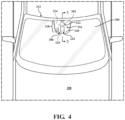
FIG. 4 is a top view of the mounting system ofFIG. 3 shown installed in window assembly coupled to a vehicle. -
FIG. 5 is a schematic cross-sectional representation of the mounting system and window assembly ofFIGS. 3 and4 taken along line 5-5 ofFIG. 4 . -
FIG. 6 is a close-up view of the mounting system ofFIGS. 3 and4 , with the mounting system further including a cover. -
FIG. 7 is a cross-sectional representation of the mounting system ofFIG. 6 . -
FIG. 8 is a perspective view of the mounting system ofFIG. 6 and the window assembly. -
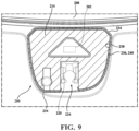
FIG. 9 is a cross-sectional representation of the mounting system ofFIG. 6 , with the mounting system including a second seal interposed between the mounting bracket and the cover. -
FIG. 10 is a bottom cross-sectional view of the mounting system ofFIG. 9 illustrating the first seal and one configuration of the second seal. -
FIG. 11 is a bottom cross-sectional view of the mounting system ofFIG. 9 illustrating the first seal and another configuration of the second seal. -
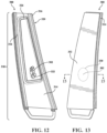
FIG. 12 is a perspective view of another mounting system according to the present disclosure. -
FIG. 13 is a perspective view of the mounting system ofFIG. 12 , with the mounting system having a mounting bracket having a mounting portion, and with the mounting portion being configured to be coupled to an exterior cover. -
FIG. 14 is a cross-sectional representation of the mounting system ofFIGS. 12 and 13 , taken along line 15-15 ofFIG. 13 -
FIG. 15 is a flowchart illustrating a method of forming a mounting system according to the present disclosure. - With reference to the Figures, wherein like numerals indicate like parts throughout the several views, various configurations of
mounting systems mounting systems component 101 relative to amounting surface 104 of avehicle 108. Thecomponent 101 may be a sensor (such as a camera), a display panel, other vehicle components (such as interior panels, roof panels, body panels, etc.), and like, or combinations thereof. As described in further detail below, the mountingsystem 100 may be configured to support more than onecomponent 101 relative to the mountingsurface 104. - Referring to
FIGS. 1-2B , a mountingsystem 100 according to the present disclosure includes a mountingbracket 114. The mountingbracket 114 is comprised of a first plastic material. In these embodiments, the first plastic material comprises a thermoplastic semi-crystalline polymer. Furthermore, the first plastic material according to these embodiments has at least one of an elastic modulus of 1000 MPa or greater and a Shore D hardness of 70 or greater. In other words, the first plastic material can have only an elastic modulus of 1000 MPa or greater, only a Shore D hardness of 70 or greater, or both an elastic modulus of 1000 MPa or greater and a Shore D hardness of 70 or greater. - In some examples, the first plastic material has an elastic modulus of between 1000 MPa and 10,000 MPa. For example, the elastic modulus of the first plastic material may be between 1000 MPa and 2000 MPa, between 2000 MPa and 3000 MPa, between 3000 MPa and 4000 MPa, between 4000 MPa and 5000 MPa, between 5000 MPa and 6000 MPa, between 6000 MPa and 7000 MPa, between 7000 MPa and 8000 MPa, between 8000 MPa and 9000 MPa, and between 9000 MPa and 10,000 MPa. In examples where the first plastic material is reinforced with additional materials (discussed below), the resulting elastic modulus may be significantly higher (e.g. as high as 200,000 MPa). One suitable technique for measuring modulus is provided in ASTM D638 (2022), which is entitled "Standard Test Method for Tensile Properties of Plastics" and is incorporated by reference in its entirety. Another suitable technique for measuring modulus is provided in ASTM D790 (2017), which is entitled "Standard Test Methods for Flexural Properties of Unreinforced and Reinforced Plastics and Electrical Insulating Materials" and is incorporated by reference in its entirety.
- In some examples, the first plastic material has a Shore D hardness of between 70 and 100. For example, the Shore D hardness of the first plastic material may be between 70 and 75, between 75 and 80, between 80 and 85, between 85 and 90, between 90 and 95, and between 95 and 100. One suitable technique for measuring Shore A/D hardness is provided in ASTM D2240 (2021), which is entitled "Standard Test Method for Rubber Property-Durometer Hardness" and is incorporated by reference in its entirety.
- In some examples, the first plastic material is selected from the group consisting of polybutylene terephthalate and polycaprolactam (i.e., PA6 nylon), but other materials are contemplated. Also, it should be appreciated that in some examples the first plastic material may be reinforced with additional materials such as carbon fiber or fiberglass.
- The size and shape of the mounting
bracket 114 is not particularly limited for the purposes of this disclosure. Accordingly, the mounting bracket is illustrated schematically inFIGS. 1-2B . The mountingbracket 114 has a mountingportion 116 that is configured to be coupled to the mountingsurface 104 of the vehicle 108 (e.g. via an adhesive). It should be appreciated that the mountingportion 116 may be coupled to the mountingsurface 104 of thevehicle 108 either directly or indirectly (e.g. with an intermediate component between the mountingportion 116 and the mounting surface 104). The mountingportion 116 may define atotal mounting area 118 bounded by aperimeter 120 of the mountingportion 116. - Still referring to
FIGS. 1-2B , the mountingportion 116 defines one ormore component receptacles 121 which may be arranged within theperimeter 120 of the mountingportion 116. The mountingbracket 114 is configured to support the component(s) 101 such that the component(s) 101 are configured to be at least partially disposed in arespective component receptacle 121. The component(s) 101 are typically removably coupled to the mountingbracket 114. For example, the component(s) 101 may be fastened to the mounting bracket 114 (e.g. via screws, clips, or the like), or the component(s) 101 may be disposed in thecomponent receptacle 121 via interference fit. Other configurations of coupling the component(s) 101 to the mountingbracket 114 are contemplated. - In one example, such as shown in
FIG. 2A , the mountingsurface 104 is a transparent pane 106 of avehicle 108. Here, the mountingsystem 100 is configured to support thecomponent 101 relative to the transparent pane 106 of thevehicle 108. Particularly, the mountingbracket 114 is configured to be coupled to the mountingsurface 104 defined by the transparent pane 106 to support thecomponent 101. In the illustrated example, thecomponent 101 is a sensor 102 (described below). Here, the mountingbracket 114 supports the sensor 102 such that the field of view FOV of the sensor 102 faces the transparent pane 106 (and, thus, the sensor 102 looks through the transparent pane 106). In this example, thecomponent receptacle 121 is further defined as a sensor aperture 122 which extends through the mountingbracket 114 and defines define asensor area 130 bounded by asensor aperture perimeter 132, with thesensor area 130 being less than the total mountingarea 118 of the mountingportion 116. In some examples, the sensor aperture(s) 122 are spaced from theperimeter 120 of the mounting portion 116 (i.e., a portion of the total mountingarea 118 is disposed between the sensor aperture 122 and theperimeter 120 of the mounting portion 116). In the example ofFIG. 2B , the mountingsurface 104 may be a sheet metal surface of thevehicle 108. Here, the mountingbracket 114 is configured to be coupled to the mountingsurface 104 defined by the transparent pane 106 to support thecomponent 101 relative to the mountingsurface 104. - In configurations where the mounting
system 100 is configured to support more than onecomponent 101, the mountingbracket 114 defines a plurality ofcomponent receptacles 121 configured to supportrespective components 101. It is to be appreciated that the mountingsystem 100 may be configured to support any number ofcomponents 101, such as two, three, four, five, six, ormore components 101. In some examples, asingle component receptacle 121 may be configured to support a plurality ofcomponents 101. - As best shown in
Figures 2A and 2B , the mountingsystem 100 also includes aseal 126. Theseal 126 is comprised of a second plastic material, different than the first plastic material of the mountingbracket 114. In these embodiments, the second plastic material comprises a thermoplastic elastomer. In some examples, the thermoplastic elastomer is further defined as thermoplastic urethane, but other materials are contemplated. Furthermore, the second plastic material according to these embodiments has at least one of an elastic modulus of 50 MPa or less and a Shore A hardness of 80 or less. In other words, the second plastic material can have only an elastic modulus of 50 MPa or less, only a Shore A hardness of 80 or less, or both an elastic modulus of 50 MPa or less and Shore A hardness of 80 or less. In some examples, the second plastic material has an elastic modulus of between greater than 0 MPa and 50 MPa or less. For example, the elastic modulus of the second plastic material may be between greater than 0 MPa and 50 MPa, between greater than 0 MPa and 40 MPa, between greater than 0 MPa and 30 MPa, between greater than 0 MPa and 20 MPa, between greater than 0 MPa and 10 MPa, and between greater than 0 MPa and 5 MPa. In some examples, the second plastic material has a Shore A hardness of between 0 and 80. For example, the Shore A hardness of the second plastic material may be between 0 and 80, between 0 and 70, between 0 and 60, between 0 and 50, between 0 and 40, between 0 and 30, between 0 and 20, and between 0 and 10. - As best shown in
FIGS. 2A and 2B , theseal 126 is coupled to the mountingbracket 114. Here, theseal 126 extends away from the mountingportion 116 such that theseal 126 is configured to engage the mountingsurface 104 to inhibit ingress of debris, dust, moisture, and the like in the space between the mountingsurface 104 and the mounting bracket 114 (e.g. thetotal mounting area 118 of the mounting portion 116). Theseal 126 extends along theperimeter 120 of the mountingportion 116 of the mounting bracket 114 (best shown inFIG. 1 ). It should be appreciated that in some embodiments, such as shown inFIG. 1 , theseal 126 extends along theentire perimeter 120 of the mountingportion 116 of the mountingbracket 114. However, in other embodiments, theseal 126 may extend partially along the perimeter 120 (e.g. one side) of the mountingportion 116 of the mountingbracket 114. In addition to inhibiting ingress of debris, dust, moisture, and the like in the space between the mountingsurface 104 and the mountingbracket 114, having theseal 126 configured to engage the mountingsurface 104 also reduces vibrations between the mountingbracket 114 and the mountingsurface 104 and also reduces noise, vibration, and harshness (NVH) that may arise between the mountingbracket 114 to the mountingsurface 104 of thevehicle 108. - A variety of approaches for coupling the
seal 126 to the mountingbracket 114 are contemplated. For example, theseal 126 may be overmolded over the mountingbracket 114. The mountingbracket 114 and theseal 126 may be formed through two shot injection molding. Specifically, the mountingbracket 114 may be injection molded with the first plastic material and then theseal 126 including the second plastic material may be injection molded over the mountingbracket 114. In other words, the mountingbracket 114 may be formed from a first injection molding operation, and theseal 126 may be formed from a second injection molding operation, subsequent to the first injection molding operation, such that theseal 126 is overmolded to the mountingbracket 114. In these examples, it is important to select the first plastic material and the second plastic material to be compatible for an overmolding process. In some examples, such as shown inFIG. 2A , the mountingbracket 114 defines abracket channel 128. In some examples, theseal 126 is at least partially disposed in thebracket channel 128. For example, theseal 126 may be overmolded into thebracket channel 128 or press-fit into thebracket channel 128 to couple theseal 126 to the mountingbracket 114. Other configurations of coupling theseal 126 to the mountingbracket 114 are contemplated. - Referring to
FIGS. 2A and 2B , the mountingsystem 100 may further include acover 134 coupled to the mountingbracket 114. Although not required, thecover 134 may conceal thecomponent 101. Thecover 134 may be fastened to the mounting bracket 114 (e.g. via screws, clips, or the like), or thecover 134 may be coupled to the mountingbracket 114 via interference fit. Other configurations of coupling thecover 134 to the mountingbracket 114 are contemplated. When present, thecover 134, when coupled to the mountingbracket 114, extends away from the mountingsurface 104. For example, referring toFIG. 2A , in configurations where the mountingbracket 114 is coupled to a transparent pane 106, the mountingbracket 114 is disposed between the transparent pane 106 and thecover 134. In another example, referring toFIG. 2B , the mountingbracket 114 may be disposed between thecover 134 and the mountingsurface 104 of thevehicle 108, such as sheet metal. Thecover 134 is typically referred to as a beauty cover or an applique. - Referring to
FIGS 3-11 , a mountingsystem 200 according to the present disclosure is configured to house asensor 202 relative to a mounting surface 204 (e.g. aninner surface 205 of atransparent pane 206 of a vehicle 108). In these examples, the mountingsystem 200 may also be referred to as "sensor mounting system 200". Thesensor 202 may be a camera, rain sensor, light sensor, light detection and ranging (LIDAR) sensor, collision sensor, forward collision sensor, and like, or combinations thereof. As described in further detail below, thesensor mounting system 200 may have more than onesensor 202. - In examples where the mounting surface 204 of the
vehicle 108 is aninner surface 205 of atransparent pane 206 of thevehicle 208, thesensor mounting system 200 and thetransparent pane 206 collectively define thewindow assembly 212. In some examples, thetransparent pane 206 is implemented as at least one pane of glass. Where thetransparent pane 206 is implemented as glass, thetransparent pane 206 is comprised of any suitable glass composition including, but not limited to, soda-lime glass, aluminosilicate glass, borosilicate glass, boro-aluminosilicate glass, and the like. Those skilled in the art realize that thetransparent pane 206 may be formed from polymeric materials such as polymethyl methacrylate, polycarbonate, polyvinyl butyral, or the like. - The
transparent pane 206 has a thickness T1. The thickness T1 of thetransparent pane 206 may be from about 0.3 mm to about 4.1 mm. More specifically, the thickness T1 may be about 0.3 mm, 0.4 mm, 0.5 mm, 0.6 mm, 0.7 mm, 0.8 mm, 0.9 mm, 1.0 mm, 1.1 mm, 1.2 mm, 1.3 mm, 1.4 mm, 1.5 mm, 1.6 mm, 1.7 mm. 1.8 mm, 1.9 mm, 2.0 mm, 2.1 mm, 2.2 mm, 2.3 mm, 2.4 mm, 2.5 mm, 2.6 mm, 2.7 mm, 2.8 mm, 2.9 mm, 3.0 mm, 3.1 mm, 3.2 mm, 3.3 mm, 3.4 mm, 3.5 mm, 3.6 mm, 3.7 mm, 3.8 mm, 3.9 mm, 4.0 mm, or 4.1 mm. - As used herein, the term "transparent", refers to a material that allows 70% or more of light transmission in a predefined visible light range to travel therethrough. Typically, the predefined visible light range is the segment of the electromagnetic spectrum that the human eye can view (i.e., visible light). Thus, the predefined visible light range typically refers to wavelengths of light from about 380 to about 780 nanometers. Where the
sensor 202 is a LIDAR sensor, however, thetransparent pane 206 may additionally or alternatively allow 70% or more of light transmission in a predefined visible light range corresponding to operative spectrum of the LIDAR sensor to travel therethrough. For example, the predefined visible light range corresponding to operative spectrum of the LIDAR sensor may be between 780 nanometers and 2000 nanometers. Other spectrums are contemplated. - In some examples, such as best shown in
FIG. 5 , thetransparent pane 206 is formed as a laminated glazing, such as a windshield. In these examples, the laminatedtransparent pane 206 includes aninner glass substrate 206A defining theinner surface 205, anouter glass substrate 206B defining anouter surface 210, and apolymeric interlayer 206C disposed between theinner glass substrate 206A and theouter glass substrate 206B. Theinner glass substrate 206A and theouter glass substrate 206B may be comprised of any suitable glass composition including, but not limited to, soda-lime glass, aluminosilicate glass, borosilicate glass, boro-aluminosilicate glass, and the like. It should be appreciated that theinner glass substrate 206A and theouter glass substrate 206B may be comprised of the same or different glass compositions. - The
inner glass substrate 206A may have a thickness TA, and theouter glass substrate 206B may have a thickness TB. The thicknesses TA, TB of theinner glass substrate 206A and theouter glass substrate 206B, respectively, may be any suitable thickness for the application. For example, the thicknesses TA, TB of theinner glass substrate 206A and theouter glass substrate 206B, respectively, may be from about 0.3 mm to about 4.1 mm. More specifically, the thicknesses TA, TB, may each be about 0.3 mm, 0.4 mm, 0.5 mm, 0.6 mm, 0.7 mm, 0.8 mm, 0.9 mm, 1.0 mm, 1.1 mm, 1.2 mm, 1.3 mm, 1.4 mm, 1.5 mm, 1.6 mm, 1.7 mm. 1.8 mm, 1.9 mm, 2.0 mm, 2.1 mm, 2.2 mm, 2.3 mm, 2.4 mm, 2.5 mm, 2.6 mm, 2.7 mm, 2.8 mm, 2.9 mm, 3.0 mm, 3.1 mm, 3.2 mm, 3.3 mm, 3.4 mm, 3.5 mm, 3.6 mm, 3.7 mm, 3.8 mm, 3.9 mm, 4.0 mm, or 4.1 mm. It should be appreciated that the thickness TA and the thickness TB can be the same or different. In one example, theinner glass substrate 206A and theouter glass substrate 206B have the same thickness (i.e., where TA is equal to TB) such that thetransparent pane 206 is considered a "symmetric" laminate. However, in another example, theinner glass substrate 206A and theouter glass substrate 206B have different thicknesses (i.e., where TA is not equal to TB) such that thetransparent pane 206 is considered an "asymmetric" laminate. All combinations of the example TA and TB values listed above and all fractional values therebetween are contemplated. - The
polymeric interlayer 206C bonds theinner glass substrate 206A and theouter glass substrate 206B such that thepolymeric interlayer 206C retains theinner glass substrate 206A and/or theouter glass substrate 206B in the event of impact or breakage of thetransparent pane 206. Thepolymeric interlayer 206C includes a polymer or thermoplastic resin, such as polyvinyl butyral (PVB), ethylene-vinyl acetate (EVA), thermoplastic polyurethane (TPU), and the like. Other suitable materials for implementing thepolymeric interlayer 206C may be utilized that provide the requisite performance characteristics regarding optical haze, adhesion to glass, and structural rigidity. Similar to theinner glass substrate 206A and theouter glass substrate 206B, thepolymeric interlayer 206C is also substantially transparent or otherwise transparent to light. - Referring to
FIGS. 3-5 , thesensor mounting system 200 includes a mountingbracket 214. The mountingbracket 214 is comprised of a first plastic material. In these embodiments, the first plastic material may have an elastic modulus of 1000 MPa or greater. The first plastic material may additionally or alternatively have a Shore D hardness of 70 or greater. In some examples, the first plastic material is a thermoplastic semi-crystalline polymer, which may be selected from the group consisting of polybutylene terephthalate and polycaprolactam (i.e., PA6 nylon), but other materials are contemplated. The mountingbracket 214 has a mountingportion 216 that is configured to be coupled to the mounting surface 204 of the vehicle 108 (e.g. to theinner surface 205 of the transparent pane 206). It should be appreciated that the mountingportion 216 may be coupled to the mounting surface 204 of thevehicle 208 either directly or indirectly (e.g. with an intermediate component between the mountingportion 216 and the mounting surface 204). For example, the mountingportion 216 may be coupled to the mounting surface 204 directly with an adhesive, or, in other examples, an intermediate component may be coupled to the mounting surface 204 and the mountingportion 216 may be coupled to the intermediate component. The mountingportion 216 defines atotal mounting area 218 bounded by a perimeter 220 of the mountingportion 216. - Still referring to
FIGS. 3-5 , the mountingportion 216 defines one ormore sensor apertures 222 within the perimeter 220 of the mountingportion 216. The mountingbracket 214 is configured to support the sensor(s) 202 such that the sensor(s) 202 is (are) aligned with arespective sensor aperture 222. For example, as best shown inFIG. 5 , in configurations where thesensor mounting system 200 is included in awindow assembly 212, the mounting bracket supports thesensor 202 such that the field of view FOV of thesensor 202 faces the transparent pane 206 (and, thus, thesensor 202 looks through the transparent pane 206). The sensor(s) 202 is (are) typically removably coupled to the mountingbracket 214. For example, the sensor(s) 202 may be fastened to the mounting bracket 214 (e.g. via screws, clips, or the like), or the sensor(s) 202 may be disposed in thesensor aperture 222 via interference fit. Other configurations of coupling the sensor(s) 202 to the mountingbracket 214 are contemplated. - In some examples, the sensor aperture(s) 222 defines a
sensor area 230 bounded by asensor aperture perimeter 232, with thesensor area 230 being less than the total mountingarea 218 of the mountingportion 216. In some examples, the sensor aperture(s) 222 is (are) spaced from the perimeter 220 of the mounting portion 216 (i.e., a portion of the total mountingarea 218 is disposed between thesensor aperture 222 and the perimeter 220 of the mounting portion 216). It should be appreciated that in addition to the seal 226 described below, thesensor mounting system 200 may further include a sensor perimeter seal coupled to the mountingbracket 214 and comprised of the second plastic material (described below) and configured to engage the mounting surface 204 to inhibit debris, dust, moisture, and the like from entering thesensor aperture 222. - In configurations where the
sensor mounting system 200 is configured to support more than onesensor 202, the mountingbracket 214 defines a plurality ofsensor apertures 222 configured to supportrespective sensors 202 such that thesensors 202 are concealed within the confines of the seal 226 (described below). It is to be appreciated that thesensor mounting system 200 may be configured to support any number ofsensors 202, such as two, three, four, five, six, ormore sensors 202. For example, the mountingportion 216 may define a first sensor aperture housing a camera, a second sensor aperture for housing a rain sensor, a third aperture for housing a light sensor, and a fourth aperture for housing a LIDAR sensor. In some examples, asingle sensor aperture 222 may be configured to support a plurality ofsensors 202. Additionally, in configurations where thesensor mounting system 200 is included in awindow assembly 212, the mountingportion 216 defines anotch 224 sized to receive a mirror button for securing arearview mirror 225 to thetransparent pane 206. - The
sensor mounting system 200 also includes a seal 226. The seal 226 is comprised of a second plastic material, different than the first plastic material of the mountingbracket 214. In these embodiments, the second plastic material has an elastic modulus of 50 MPa or less. The second plastic material may additionally or alternatively have a Shore A hardness of 80 or less. In some examples, the second plastic material is a thermoplastic elastomer, which may be further defined as thermoplastic urethane, but other materials are contemplated. - As best shown in
FIG. 5 , the seal 226 is coupled to the mountingbracket 214. Here, the seal 226 extends away from the mountingportion 216 such that the seal 226 is configured to engage the mounting surface 204 (e.g. theinner surface 205 of the transparent pane 206) to inhibit ingress of debris, dust, moisture, and the like in the space between the mounting surface 204 and the mounting bracket 214 (e.g. thetotal mounting area 218 of the mounting portion 216). The seal 226 extends along the perimeter 220 of the mountingportion 216 of the mounting bracket 214 (best shown inFIG. 3 ). It should be appreciated that in some embodiments, such as shown inFIG. 3 , the seal 226 extends along the entire perimeter 220 of the mountingportion 216 of the mountingbracket 214. However, in other embodiments, the seal 226 may extend partially along the perimeter 120 (e.g. one side) of the mountingportion 216 of the mountingbracket 214. Having the seal 226 extend along the perimeter 220 of the mountingportion 216 and configured to engage the mounting surface 204 inhibits debris, dust, moisture, and the like from not only entering thetotal mounting area 218, but also from entering the sensor aperture(s) 222. Additionally, having the seal 226 configured to engage the mounting surface 204 reduces vibrations between the mountingbracket 214 and the mounting surface 204 and also reduces noise, vibration, and harshness (NVH) that may arise between the mountingbracket 214 to the mounting surface 204 of thevehicle 208. - A variety of approaches for coupling the seal 226 to the mounting
bracket 214 are contemplated. For example, the seal 226 may be overmolded over the mountingbracket 214. The mountingbracket 214 and the seal 226 may be formed through two shot injection molding. Specifically, the mountingbracket 214 may be injection molded with the first plastic material and then the seal 226 including the second plastic material may be injection molded over the mountingbracket 214. In other words, the mountingbracket 214 may be formed from a first injection molding operation, and the seal 226 may be formed from a second injection molding operation, subsequent to first injection molding operation, such that the seal 226 is overmolded to the mountingbracket 214. In these examples, it is important to select the first plastic material and the second plastic material to be compatible for an overmolding process. In some examples, such as shown inFIG. 5 , the mountingbracket 214 defines abracket channel 228. In some examples, the seal 226 is at least partially disposed in thebracket channel 228. For example, the seal 226 may overmolded into thebracket channel 228 or press-fit into thebracket channel 228 to couple the seal 226 to the mountingbracket 214. Other configurations of coupling the seal 226 to the mountingbracket 214 are contemplated. - Referring to
FIGS. 5-11 , thesensor mounting system 200 may further include acover 234 coupled to the mountingbracket 214. Although not required, thecover 234 may conceal thesensor 202. Thecover 234 may be fastened to the mounting bracket 214 (e.g. via screws, clips, or the like), or thecover 234 may be coupled to the mountingbracket 214 via interference fit. Other configurations of coupling thecover 234 to the mountingbracket 214 are contemplated. When present, thecover 234, when coupled to the mountingbracket 214, extends away from the mounting surface 204. For example, referring toFIG. 7 , in configurations where thesensor mounting system 200 is included in awindow assembly 212, the mountingbracket 214 is disposed between theinner surface 205 of thetransparent pane 206 and thecover 234. Thecover 234 is typically referred to as a beauty cover. As shown in the illustrated configurations, where thesensor mounting system 200 is included in awindow assembly 212, thecover 234 may define a through-hole 235 for receiving supporting arear view mirror 225. - In one embodiment, the seal 226 is further defined as a first seal 226, and the
sensor mounting system 200 may include asecond seal 236. Thesecond seal 236 is interposed between the mountingbracket 214 and thecover 234, as shown inFIGS. 10 and 11 . In other words, thesecond seal 236 is coupled to one of the mountingbracket 214 and thecover 234 and arranged to abut the other of the mountingbracket 214 and thecover 234 to inhibit debris, dust, moisture, and the like, from entering therebetween. Thesecond seal 236, like the first seal 226, may be formed from the second plastic material. A variety of approaches for coupling thesecond seal 236 to one of the mountingbracket 214 and thecover 234 are contemplated. In some examples, referring toFIGS. 10 and 11 , the mountingbracket 214 has acoupling portion 238 facing opposite the mountingportion 216, and thesecond seal 236 may disposed around aperimeter 240 of thecoupling portion 238. In other examples, thesecond seal 236 is overmolded over one of the mountingbracket 214 and thecover 234. - In another embodiment, another mounting
system 300 according to the present disclosure is generally shown inFIGS. 12-14 . Similar to thesensor mounting system 200 described above in the context ofFIGS 5-11 , thesensor mounting system 300 is configured to house asensor 302 relative to a mountingsurface 304 of avehicle 308. Here, the mountingsystem 300 may also be referred to as "sensor mounting system 300". In these examples, the mountingsurface 304 of thevehicle 308 includes, for example, a pillar of thevehicle 308, such as an A-Pillar, B-Pillar, or C-Pillar, or otherwise to the exterior of the vehicle. Similar to thesensor 202 described above in the context ofFIGS 5-11 , thesensor 302 may be a camera, rain sensor, light sensor, light detection and ranging (LIDAR) sensor, collision sensor, forward collision sensor, and like, or combinations thereof, and thesensor mounting system 300 may have more than onesensor 302. - With continued reference to
FIGS. 12-14 , thesensor mounting system 300 includes a mountingbracket 314 comprised of the first plastic material (described above). The mountingbracket 314 has a mountingportion 316 that is configured to be coupled to the mountingsurface 304 of thevehicle 308, such as sheet metal of the vehicle and/or to the material that is behind an A-Pillar, B-Pillar, C-Pillar, etc. The mountingportion 316 defines atotal mounting area 318 bounded by aperimeter 320 of the mountingportion 316. Similar to as described above in the context ofFIGS. 5-11 , the mountingportion 316 defines one ormore sensor apertures 322 within theperimeter 320 of the mountingportion 316. The mountingbracket 314 is configured to support the sensor(s) 302 such that the sensor(s) 302 are aligned with arespective sensor aperture 322. The sensor(s) 302 is (are) typically removably coupled to the mountingbracket 314. For example, the sensor(s) 302 may be fastened to the mounting bracket 314 (e.g. via screws, clips, or the like), or the sensor(s) 302 may be disposed in thesensor aperture 322 via interference fit. Other configurations of coupling the sensor(s) 302 to the mountingbracket 314 are contemplated. - The
sensor mounting system 300 also includes aseal 326 comprised of the second plastic material (described above). Similar to as described above in the context ofFIGS. 5-11 , a variety of approaches for coupling theseal 326 to the mountingbracket 314 are contemplated. For example, similar to as described above in the context ofFIGS. 5-11 , the mountingbracket 314 may define a bracket channel (not shown) for receiving theseal 326. - In the present configurations, the
seal 326 extends away from the mountingportion 316 such that theseal 326 is configured to engage the mountingsurface 304 of the vehicle 308 (e.g. the sheet metal of thevehicle 308 and/or to the material that is behind an A-Pillar, B-Pillar, C-Pillar, etc.) to inhibit ingress of debris, dust, moisture, and the like in the space between the mountingsurface 304 and the mountingbracket 314. Having theseal 326 configured to engage the mountingsurface 304 of thevehicle 308 to inhibit ingress of debris between the mountingportion 316 and the mountingsurface 304 of thevehicle 308 inhibits debris from not only entering the space between the mountingsurface 304 and the mountingbracket 314, but also from entering the sensor aperture(s) 322. - With particular reference to
FIGS. 13 and14 , similar to as described above in the context ofFIGS 5-11 , thesensor mounting system 300 may also include anexterior cover 334.FIG. 13 shows the mountingbracket 314 rotated approximately 180 degrees from the view ofFIG. 12 . In other words, the mountingportion 316 shown inFIG. 12 is coupled to mountingsurface 304 thevehicle 308, and theexterior cover 334 is facing the exterior of thevehicle 308 with thesensor 302 viewing the exterior of thevehicle 308 through the exterior cover 334 (illustrated schematically with reference numeral 330). In some examples, at least theportion 330 of theexterior cover 334 that is aligned with the field of view (FOV) of thesensor 302 may be transparent. In these examples, theexterior cover 334 may comprise glass or a transparent polymeric material, such as described above in the context oftransparent pane 206. Theexterior cover 334 may also include anopaque mask 332 disposed on portions of theexterior cover 334 that are not aligned with the field of view FOV of thesensor 302 to conceal any components beneath theexterior cover 334. - The present disclosure is also directed to a
method 400 of forming thewindow assembly 212 according to the present disclosure. Referring toFIG. 15 , themethod 400 includes astep 402 of providing atransparent pane 206 having aninner surface 205 and an opposingouter surface 210. Themethod 400 of forming thewindow assembly 212 also includes astep 404 of forming a mountingbracket 214 having a mountingportion 216 defining atotal mounting area 218 bounded by a perimeter 220 of the mountingportion 216. The mountingportion 216 further defines asensor aperture 222 within the perimeter 220 of the mountingportion 216. Similar to as described above, the mountingbracket 214 is comprised of a first plastic material having at least one of an elastic modulus of 1000 MPa or greater and a Shore D hardness of 80 or greater. Themethod 400 further includes astep 406 of coupling a seal 226 to the mountingbracket 214 along the perimeter 220 of the mountingportion 216. Similar to as described above, the seal 226 is comprised of a second plastic material, different than the first plastic material, and having at least one of an elastic modulus of 50 MPa or less and a Shore A hardness of 80 or less. In some examples, thestep 406 may further include overmolding the seal 226 over the mountingbracket 214 along the perimeter 220 of the mountingportion 216. Themethod 400 additionally includes astep 408 of coupling the mountingbracket 214 to theinner surface 205 of the transparent pane 206 (e.g. via an adhesive, directly or indirectly) such that the seal 226 engages theinner surface 205 of thetransparent pane 206 to inhibit ingress of debris between the mountingportion 216 and the inner surface of thetransparent pane 206. - Several embodiments have been described in the foregoing description. However, the embodiments described herein are not intended to be exhaustive or limit the invention to any particular form. The terminology which has been used is intended to be in the nature of words of description rather than of limitation. Many modifications and variations are possible in light of the above teachings and the invention may be practiced otherwise than as specifically described.
- Various additional alterations and changes beyond those already mentioned herein can be made to the above-described embodiments. This disclosure is presented for illustrative purposes and should not be interpreted as an exhaustive description of all embodiments or to limit the scope of the claims to the specific elements illustrated or described in connection with these embodiments. For example, and without limitation, any individual element(s) of the described embodiments may be replaced by alternative elements that provide substantially similar functionality or otherwise provide adequate operation. This includes, for example, presently known alternative elements, such as those that might be currently known to one skilled in the art, and alternative elements that may be developed in the future, such as those that one skilled in the art might, upon development, recognize as an alternative. Any reference to claim elements in the singular, for example, using the articles "a," "an," "the" or "said," is not to be construed as limiting the element to the singular. It will be further appreciated that the terms "include," "includes," and "including" have the same meaning as the terms "comprise," "comprises," and "comprising."
- The present disclosure also comprises the following clauses, with specific features laid out in dependent clauses, that may specifically be implemented as described in greater detail with reference to the configurations and drawings above.
-
- I. A window assembly configured to house a sensor, the window assembly comprising:
- a transparent pane including an inner surface and an opposing outer surface;
- a mounting bracket including a mounting portion coupled to the inner surface of the transparent pane, the mounting portion defining a total mounting area bounded by a perimeter of the mounting portion, and defining a sensor aperture within the perimeter of the mounting portion, wherein the mounting bracket comprises a first plastic material having at least one of an elastic modulus of 1000 MPa or greater and a Shore D hardness of 70 or greater, and wherein the mounting bracket is configured to support the sensor such that the sensor is aligned with the sensor aperture; and
- a seal coupled to the mounting bracket along the perimeter of the mounting portion and engaging the inner surface of the transparent pane to inhibit ingress of debris between the mounting portion and the inner surface of the transparent pane, wherein the seal comprises a second plastic material, different than the first plastic material, and having at least one of an elastic modulus of 50 MPa or less and a Shore A hardness of 80 or less.
- II. The window assembly as set forth in clause I, wherein the mounting bracket defines a bracket channel, and wherein the seal is at least partially disposed in the bracket channel.
- III. The window assembly as set forth in any one of clauses I or II further comprising a cover coupled to the mounting bracket for concealing the sensor.
- IV. The window assembly as set forth in clause III, wherein the seal is further defined as a first seal, and wherein the window assembly further comprises a second seal interposed between the mounting bracket and the cover to inhibit ingress of debris therebetween.
- V. The window assembly as set forth in clause IV, wherein the mounting bracket further includes a coupling portion facing opposite the mounting portion; and
wherein the second seal is disposed around a perimeter of the coupling portion. - VI. The window assembly as set forth in any one of clauses I to V, wherein the mounting bracket defines a notch configured to receive a rearview mirror of a vehicle.
- VII. The window assembly as set forth in any one of clauses I to VI, wherein the first plastic material is a thermoplastic semi-crystalline polymer.
- VIII. The window assembly as set forth in any one of clauses I to VII, wherein the first plastic material is selected from the group consisting of polybutylene terephthalate and polycaprolactam.
- IX. The window assembly as set forth in any one of clauses I to VIII, wherein the second plastic material is a thermoplastic elastomer.
- X. The window assembly as set forth in clause IX, wherein the thermoplastic elastomer is a thermoplastic urethane.
- XI. A method of forming a window assembly configured to house one or more sensors, the method comprising:
- providing a transparent pane having an inner surface and an opposing outer surface;
- forming a mounting bracket having a mounting portion defining a total mounting area bounded by a perimeter of the mounting portion, and defining a sensor aperture within the perimeter of the mounting portion, wherein the mounting bracket comprises a first plastic material having at least one of an elastic modulus of 1000 MPa or greater and a Shore D hardness of 70 or greater, and wherein the mounting bracket is configured to support the sensor such that the sensor is aligned with the sensor aperture;
- coupling a seal to the mounting bracket along the perimeter of the mounting portion, the seal comprising a second plastic material, different than the first plastic material, and having at least one of an elastic modulus of 50 MPa or less and a Shore A hardness of 80 or less; and
- coupling the mounting bracket to the inner surface of the transparent pane such that the seal engages the inner surface of the transparent pane to inhibit ingress of debris between the mounting portion and the inner surface of the transparent pane.
- XII. The method according to clause XI, wherein the step of coupling the seal to the mounting bracket further comprises overmolding the seal over the mounting bracket along the perimeter of the mounting portion.
- XIII. A mounting system configured to support a component relative to a mounting surface of a vehicle, the mounting system comprising:
- a mounting bracket including a mounting portion configured to be coupled to the mounting surface of the vehicle, the mounting bracket defining a component receptacle configured to support the component, wherein the mounting bracket comprises a first plastic material, and wherein the first plastic material comprises a thermoplastic semi-crystalline polymer having at least one of an elastic modulus of 1000 MPa or greater and a Shore D hardness of 70 or greater; and
- a seal coupled to the mounting bracket and configured to engage the mounting surface of the vehicle to inhibit ingress of debris between the mounting portion and the mounting surface of the vehicle, wherein the seal comprises a second plastic material, different than the first plastic material, and wherein the second plastic material comprises a thermoplastic elastomer having at least one of an elastic modulus of 50 MPa or less and a Shore A hardness of 80 or less;
- wherein the mounting bracket is formed from a first injection molding operation, and wherein the seal is formed from a second injection molding operation, subsequent to first injection molding operation, such that the seal is overmolded to the mounting bracket.
- XIV. The mounting system as set forth in clause XIII, wherein the mounting bracket defines a bracket channel, and wherein the seal is at least partially disposed in the bracket channel.
- XV. The mounting system as set forth in any one of clauses XIII or XIV further comprising a cover coupled to the mounting bracket for at least partially concealing the mounting bracket.
- XVI. The mounting system as set forth in clause XV, wherein the seal is further defined as a first seal, and wherein the window assembly further comprises a second seal interposed between the mounting bracket and the cover to inhibit ingress of debris therebetween.
- XVII. The mounting system as set forth in any one of clauses XIII to XVI, wherein the first plastic material is a thermoplastic semi-crystalline polymer.
- XVIII. The mounting system as set forth in any one of clauses XIII to XVII, wherein the first plastic material is selected from the group consisting of polybutylene terephthalate and polycaprolactam.
- XIX. The mounting system as set forth in any one of clauses XIII to XVIII, wherein the second plastic material is a thermoplastic elastomer.
- XX. The mounting system as set forth in clause XIX, wherein the thermoplastic elastomer is a thermoplastic urethane.
- XXI. The mounting system as set forth in any one of clauses XIII to XX, wherein the component is further defined as a sensor, and the component receptacle is further defined as a sensor aperture extending through the mounting bracket; and
wherein the mounting bracket is configured to support the sensor such that the sensor is aligned with the sensor aperture. - XXII. A window assembly comprising:
- the mounting system as set forth in clause XXI; and
- a transparent pane including an inner surface and an opposing outer surface, wherein the inner surface defines the mounting surface of the vehicle;
- wherein the seal engages the inner surface of the transparent pane to inhibit ingress of debris between the mounting portion and the inner surface of the transparent pane.
- Including the following clauses:
- 1. A window assembly configured to house a sensor, the window assembly comprising:
- a transparent pane including an inner surface and an opposing outer surface;
- a mounting bracket including a mounting portion coupled to the inner surface of the transparent pane, the mounting portion defining a total mounting area bounded by a perimeter of the mounting portion, and defining a sensor aperture within the perimeter of the mounting portion, wherein the mounting bracket comprises a first plastic material having at least one of an elastic modulus of 1000 MPa or greater and a Shore D hardness of 70 or greater, and wherein the mounting bracket is configured to support the sensor such that the sensor is aligned with the sensor aperture; and
- a seal coupled to the mounting bracket along the perimeter of the mounting portion and engaging the inner surface of the transparent pane to inhibit ingress of debris between the mounting portion and the inner surface of the transparent pane, wherein the seal comprises a second plastic material, different than the first plastic material, and having at least one of an elastic modulus of 50 MPa or less and a Shore A hardness of 80 or less.
- 2. The window assembly as set forth in clause 1, wherein the mounting bracket defines a bracket channel, and wherein the seal is at least partially disposed in the bracket channel.
- 3. The window assembly as set forth in any one of clause 1 or 2 further comprising a cover coupled to the mounting bracket for concealing the sensor.
- 4. The window assembly as set forth in clause 3, wherein the seal is further defined as a first seal, and wherein the window assembly further comprises a second seal interposed between the mounting bracket and the cover to inhibit ingress of debris therebetween, and, optionally, wherein the mounting bracket further includes a coupling portion facing opposite the mounting portion, and the second seal is disposed around a perimeter of the coupling portion.
- 5. The window assembly as set forth in any one of clauses 1 to 4, wherein the mounting bracket defines a notch configured to receive a rearview mirror of a vehicle.
- 6. The window assembly as set forth in any one of clauses 1 to 5, wherein the first plastic material is a thermoplastic semi-crystalline polymer; and/or
wherein the first plastic material is selected from the group consisting of polybutylene terephthalate and polycaprolactam. - 7. The window assembly as set forth in any one of clauses 1 to 6, wherein the second plastic material is a thermoplastic elastomer, and, optionally, wherein the thermoplastic elastomer is a thermoplastic urethane.
- 8. A method of forming a window assembly configured to house one or more sensors, the method comprising:
- providing a transparent pane having an inner surface and an opposing outer surface;
- forming a mounting bracket having a mounting portion defining a total mounting area bounded by a perimeter of the mounting portion, and defining a sensor aperture within the perimeter of the mounting portion, wherein the mounting bracket comprises a first plastic material having at least one of an elastic modulus of 1000 MPa or greater and a Shore D hardness of 70 or greater, and wherein the mounting bracket is configured to support the sensor such that the sensor is aligned with the sensor aperture;
- coupling a seal to the mounting bracket along the perimeter of the mounting portion, the seal comprising a second plastic material, different than the first plastic material, and having at least one of an elastic modulus of 50 MPa or less and a Shore A hardness of 80 or less; and
- coupling the mounting bracket to the inner surface of the transparent pane such that the seal engages the inner surface of the transparent pane to inhibit ingress of debris between the mounting portion and the inner surface of the transparent pane.
- 9. The method according to clause 8, wherein the step of coupling the seal to the mounting bracket further comprises overmolding the seal over the mounting bracket along the perimeter of the mounting portion.
- 10. A mounting system configured to support a component relative to a mounting surface of a vehicle, the mounting system comprising:
- a mounting bracket including a mounting portion configured to be coupled to the mounting surface of the vehicle, the mounting bracket defining a component receptacle configured to support the component, wherein the mounting bracket comprises a first plastic material, and wherein the first plastic material comprises a thermoplastic semi-crystalline polymer having at least one of an elastic modulus of 1000 MPa or greater and a Shore D hardness of 70 or greater; and
- a seal coupled to the mounting bracket and configured to engage the mounting surface of the vehicle to inhibit ingress of debris between the mounting portion and the mounting surface of the vehicle, wherein the seal comprises a second plastic material, different than the first plastic material, and wherein the second plastic material comprises a thermoplastic elastomer having at least one of an elastic modulus of 50 MPa or less and a Shore A hardness of 80 or less;
- wherein the mounting bracket is formed from a first injection molding operation, and wherein the seal is formed from a second injection molding operation, subsequent to first injection molding operation, such that the seal is overmolded to the mounting bracket.
- 11. The mounting system as set forth in clause 10, wherein the mounting bracket defines a bracket channel, and wherein the seal is at least partially disposed in the bracket channel.
- 12. The mounting system as set forth in any one of clause 10 or 11 further comprising a cover coupled to the mounting bracket for at least partially concealing the mounting bracket.
- 13. The mounting system as set forth in any one of clauses 10 to 12, wherein the first plastic material is a thermoplastic semi-crystalline polymer; and/or
wherein the first plastic material is selected from the group consisting of polybutylene terephthalate and polycaprolactam. - 14. The mounting system as set forth in any one of clauses 10 to 13, wherein the second plastic material is a thermoplastic elastomer, and optionally, wherein the thermoplastic elastomer is a thermoplastic urethane.
- 15. The mounting system as set forth in any one of clauses 10 to 14, wherein the component is further defined as a sensor, and the component receptacle is further defined as a sensor aperture extending through the mounting bracket; and
wherein the mounting bracket is configured to support the sensor such that the sensor is aligned with the sensor aperture.
Claims (15)
- A mounting system (100, 200, 300) configured to support a component (101) relative to a mounting surface (104, 204, 304) of a vehicle (108, 208, 308), the mounting system (100, 200, 300) comprising:a mounting bracket (114, 214, 314) including a mounting portion (116, 216, 316) configured to be coupled to the mounting surface (104, 204, 304) of the vehicle (108, 208, 308), the mounting bracket (114, 214, 314) defining a component receptacle (121) configured to support the component (101), wherein the mounting bracket (114, 214, 314) comprises a first plastic material having at least one of an elastic modulus of 1000 MPa or greater and a Shore D hardness of 70 or greater; anda seal (126, 226, 326) coupled to the mounting bracket (114, 214, 314) and configured to engage the mounting surface (104, 204, 304) of the vehicle (108, 208, 308) to inhibit ingress of debris between the mounting portion (116, 216, 316) and the mounting surface (104, 204, 304) of the vehicle (108, 208, 308), wherein the seal (126, 226, 326) comprises a second plastic material different than the first plastic material and having at least one of an elastic modulus of 50 MPa or less and a Shore A hardness of 80 or less;wherein the mounting bracket (114, 214, 314) is formed from a first injection molding operation, and wherein the seal (126, 226, 326) is formed from a second injection molding operation, subsequent to first injection molding operation, such that the seal (126, 226, 326) is overmolded to the mounting bracket (114, 214, 314).
- The mounting system (100, 200, 300) as set forth in claim 1, wherein the component (101) is further defined as a sensor (102, 202, 302), and the component receptacle (121) is further defined as a sensor aperture (122, 222, 322) extending through the mounting bracket (114, 214, 314); and
wherein the mounting bracket (114, 214, 314) is configured to support the sensor (102, 202, 302) such that the sensor (102, 202, 302) is aligned with the sensor aperture (122, 222, 322). - The mounting system (100, 200, 300) as set forth in claim 2, wherein the sensor (102, 202, 302) includes at least one of a camera, a rain sensor, a light sensor, a light detection and ranging (LIDAR) sensor, and a collision sensor.
- The mounting system (100, 200, 300) as set forth in any one of claims 2 or 3, wherein the sensor (102, 202, 302) has a field of view (FOV); andwherein the mounting system (100, 200, 300) further comprises a cover (134, 234, 334) coupled to the mounting bracket (114, 214, 314); and, optionallywherein at least a portion (130, 230, 330) of the cover (134, 234, 334) that is aligned with the field of view (FOV) of the sensor (102, 202, 302) is transparent.
- The mounting system (100, 200, 300) as set forth in claim 4, wherein the cover (134, 234, 334) includes an opaque mask (332) disposed over at least a portion of the cover (134, 234, 334) that is not aligned with the field of view (FOV) of the sensor (102, 202, 302).
- The mounting system (100, 200, 300) as set forth in any one of claims 1 to 5, wherein the first plastic material is a thermoplastic semi-crystalline polymer.
- The mounting system (100, 200, 300) as set forth in claim 6, wherein the first plastic material is selected from the group consisting of polybutylene terephthalate and polycaprolactam.
- The mounting system (100, 200, 300) as set forth in any one of claims 1 to 7, wherein the second plastic material is a thermoplastic elastomer.
- The mounting system (100, 200, 300) as set forth in claim 8, wherein the thermoplastic elastomer is a thermoplastic urethane.
- The mounting system (100, 200, 300) as set forth in any one of claims 1 to 9 further comprising a cover (134, 234, 334) coupled to the mounting bracket (114, 214, 314) and comprising at least one of glass and a transparent polymeric material.
- The mounting system (100, 200, 300) as set forth in claim 10, wherein the mounting bracket (114, 214, 314) is disposed between the cover (134, 234, 334) and the mounting surface (104, 204, 304) of the vehicle (108, 208, 308).
- The mounting system (100, 200, 300) as set forth in claim 11, wherein the cover (134, 234, 334) includes an opaque mask (332) disposed over at least a portion of the cover (134, 234, 334) for at least partially concealing the mounting bracket (114, 214, 314).
- The mounting system (100, 200, 300) as set forth in any one of claims 10 to 12, wherein the seal (126, 226, 326) is further defined as a first seal (126, 226, 326), and wherein the mounting system (100, 200, 300) further comprises a second seal (236) interposed between the mounting bracket (114, 214, 314) and the cover (134, 234, 334) to inhibit ingress of debris therebetween.
- The mounting system (100, 200, 300) as set forth in any one of claims 1 to 13, wherein the mounting bracket (114, 214, 314) defines a bracket channel (128, 228), and wherein the seal (126, 226, 326) is at least partially disposed in the bracket channel (128, 228).
- The mounting system (100, 200, 300) as set forth in any one of claims 1 to 14, wherein the mounting surface (104, 204, 304) of the vehicle (108, 208, 308) is further defined as sheet metal of the vehicle (108, 208, 308).
Applications Claiming Priority (3)
| Application Number | Priority Date | Filing Date | Title |
|---|---|---|---|
| US202363443580P | 2023-02-06 | 2023-02-06 | |
| US18/431,403 US12123747B2 (en) | 2023-02-06 | 2024-02-02 | Mounting system, a window assembly including the same, and a method of forming the window assembly |
| EP24156072.1A EP4410602B1 (en) | 2023-02-06 | 2024-02-06 | A mounting system, a window assembly including the same, and a method of forming the window assembly |
Related Parent Applications (2)
| Application Number | Title | Priority Date | Filing Date |
|---|---|---|---|
| EP24156072.1A Division EP4410602B1 (en) | 2023-02-06 | 2024-02-06 | A mounting system, a window assembly including the same, and a method of forming the window assembly |
| EP24156072.1A Division-Into EP4410602B1 (en) | 2023-02-06 | 2024-02-06 | A mounting system, a window assembly including the same, and a method of forming the window assembly |
Publications (2)
| Publication Number | Publication Date |
|---|---|
| EP4578741A2 true EP4578741A2 (en) | 2025-07-02 |
| EP4578741A3 EP4578741A3 (en) | 2025-07-23 |
Family
ID=89853532
Family Applications (2)
| Application Number | Title | Priority Date | Filing Date |
|---|---|---|---|
| EP25177245.5A Pending EP4578741A3 (en) | 2023-02-06 | 2024-02-06 | A mounting system, a window assembly including the same, and a method of forming the window assembly |
| EP24156072.1A Active EP4410602B1 (en) | 2023-02-06 | 2024-02-06 | A mounting system, a window assembly including the same, and a method of forming the window assembly |
Family Applications After (1)
| Application Number | Title | Priority Date | Filing Date |
|---|---|---|---|
| EP24156072.1A Active EP4410602B1 (en) | 2023-02-06 | 2024-02-06 | A mounting system, a window assembly including the same, and a method of forming the window assembly |
Country Status (3)
| Country | Link |
|---|---|
| US (1) | US12123747B2 (en) |
| EP (2) | EP4578741A3 (en) |
| JP (1) | JP7745021B2 (en) |
Families Citing this family (1)
| Publication number | Priority date | Publication date | Assignee | Title |
|---|---|---|---|---|
| US20250042230A1 (en) * | 2023-08-03 | 2025-02-06 | GM Global Technology Operations LLC | Display systems releasably attached to a windshield assembly and processes thereof |
Family Cites Families (28)
| Publication number | Priority date | Publication date | Assignee | Title |
|---|---|---|---|---|
| US6250148B1 (en) | 1998-01-07 | 2001-06-26 | Donnelly Corporation | Rain sensor mount for use in a vehicle |
| US6824281B2 (en) | 2002-01-31 | 2004-11-30 | Donnelly Corporation | Vehicle accessory module |
| DE10209615A1 (en) | 2002-03-05 | 2003-09-18 | Bosch Gmbh Robert | Device and method for fixing a sensor means |
| DE10237608A1 (en) | 2002-08-16 | 2004-02-26 | Hella Kg Hueck & Co. | Camera arrangement for motor vehicles |
| US6795237B1 (en) | 2003-06-02 | 2004-09-21 | Ford Motor Company | Overhead console active night vision system for an interior cabin of a vehicle |
| DE10355205A1 (en) * | 2003-11-26 | 2005-07-07 | Hella Kgaa Hueck & Co. | Mounting for forward-looking camera in car, is fitted to windscreen and incorporates holder for interior rear view mirror |
| US8256821B2 (en) | 2004-12-15 | 2012-09-04 | Magna Donnelly Engineering Gmbh | Accessory module system for a vehicle window |
| US20070216768A1 (en) | 2006-03-14 | 2007-09-20 | Ford Global Technologies, Llc | Device and method for outwardly looking ir camera mounted inside vehicles particularly suited for pre-crash sensing and pedestrian detection |
| US7989725B2 (en) * | 2006-10-30 | 2011-08-02 | Ink-Logix, Llc | Proximity sensor for a vehicle |
| DE102006059554B4 (en) | 2006-12-16 | 2022-03-10 | Kostal Automobil Elektrik Gmbh & Co. Kg | Optoelectronic sensor device |
| DE102008050320A1 (en) | 2008-10-04 | 2010-04-08 | Daimler Ag | Support device for attachment to a window of a motor vehicle |
| WO2013019795A1 (en) | 2011-08-02 | 2013-02-07 | Magna Electronics Inc. | Vehicular camera system |
| US9487161B2 (en) | 2013-10-04 | 2016-11-08 | Magna Mirrors Of America, Inc. | Accessory system for a vehicle |
| US9352692B2 (en) | 2014-03-10 | 2016-05-31 | Magna Mirrors Of America, Inc. | Vehicle vision system with camera and mirror mount |
| US9896039B2 (en) | 2014-05-09 | 2018-02-20 | Magna Electronics Inc. | Vehicle vision system with forward viewing camera |
| WO2016129699A1 (en) | 2015-02-13 | 2016-08-18 | 日本板硝子株式会社 | Windshield |
| JP6785541B2 (en) | 2015-07-30 | 2020-11-18 | 日本板硝子株式会社 | Glass plate module |
| JP6455357B2 (en) | 2015-08-05 | 2019-01-23 | スズキ株式会社 | Mounting structure for in-vehicle equipment |
| WO2018110465A1 (en) | 2016-12-12 | 2018-06-21 | 日本板硝子株式会社 | Windshield, glass product for windshield, and antifogging member |
| US10479289B2 (en) | 2017-08-22 | 2019-11-19 | Trw Automotive U.S. Llc | Active surround view system with self-cleaning mechanism |
| EP3700782B1 (en) | 2017-10-26 | 2022-04-27 | Saint-Gobain Glass France | Vehicle attachment with integrated camera module |
| JP7237077B2 (en) * | 2018-01-24 | 2023-03-10 | セントラル硝子株式会社 | Glazing with frames for information acquisition systems |
| CN110579743A (en) | 2018-06-08 | 2019-12-17 | 日本电产株式会社 | holder and sensor device |
| JP7024634B2 (en) | 2018-07-09 | 2022-02-24 | Agc株式会社 | Mounting base and vehicle glass with mounting base |
| DE102018125065B3 (en) | 2018-10-10 | 2019-11-21 | Bayerische Motoren Werke Aktiengesellschaft | Holding device for holding at least one driver assistance sensor unit and arrangement of a holding device |
| CN111771142B (en) | 2019-01-15 | 2024-03-29 | 法国圣戈班玻璃厂 | Vehicle glazing with integrated sensor module |
| US10981520B1 (en) | 2019-11-14 | 2021-04-20 | Zf Friedrichshafen Ag | Driver assist system for a vehicle |
| DE102019134006A1 (en) | 2019-12-11 | 2021-06-17 | Bayerische Motoren Werke Aktiengesellschaft | Lens hood for a vehicle camera |
-
2024
- 2024-02-02 US US18/431,403 patent/US12123747B2/en active Active
- 2024-02-06 EP EP25177245.5A patent/EP4578741A3/en active Pending
- 2024-02-06 JP JP2024016102A patent/JP7745021B2/en active Active
- 2024-02-06 EP EP24156072.1A patent/EP4410602B1/en active Active
Also Published As
| Publication number | Publication date |
|---|---|
| JP7745021B2 (en) | 2025-09-26 |
| JP2024111840A (en) | 2024-08-19 |
| US12123747B2 (en) | 2024-10-22 |
| EP4410602A3 (en) | 2024-09-18 |
| US20240263975A1 (en) | 2024-08-08 |
| EP4410602A2 (en) | 2024-08-07 |
| EP4410602B1 (en) | 2025-07-23 |
| EP4578741A3 (en) | 2025-07-23 |
Similar Documents
| Publication | Publication Date | Title |
|---|---|---|
| KR102649667B1 (en) | Vehicle window with integrated sensor module | |
| US6758510B1 (en) | Vehicle A-pillar trim components with integrated rear-view mirrors | |
| KR20120120949A (en) | Flashing glass panel for a vehicle, and method for manufacturing same | |
| KR20120120950A (en) | Luminous vehicle glazing and manufacture thereof | |
| US20110080018A1 (en) | Seal moldings for vehicles | |
| EP4410602A2 (en) | A mounting system, a window assembly including the same, and a method of forming the window assembly | |
| CN109963748B (en) | Vehicle attachment with integrated camera module | |
| JP4754044B2 (en) | Laminated glass with high resistance to impact testing | |
| RU2764891C1 (en) | Composite window glass | |
| US11247539B2 (en) | Windshield with molding and connective structure for cowl louver and windshield with molding | |
| CN118438960A (en) | Mounting system, window assembly including the same, and method of forming a window assembly | |
| KR20210089815A (en) | Door for vehicle | |
| KR101245979B1 (en) | Photochromatic effect for polycarbonate glazing applications | |
| US10179550B1 (en) | Flush-mount sensor lens assembly | |
| DE102006022925B4 (en) | Vehicle component with a concealed sensor | |
| JPH06340221A (en) | Panel for automobile | |
| EP1934089B1 (en) | Molded sliding window assembly | |
| EP0046002A1 (en) | Decorative trim strip | |
| US5858483A (en) | Bilaminate window glass assembly | |
| GB2422960A (en) | Vehicle headliner antenna mounting structure | |
| CN120530026A (en) | Vehicle glazing for a motor vehicle, method for producing a vehicle glazing, and motor vehicle having such a vehicle glazing | |
| EP1059161A2 (en) | Crystal for windows of vehicles | |
| US20220250446A1 (en) | Resin window panel and bonding structure of resin window panel and vehicle body | |
| CN119894670A (en) | Composite glass pane with integrated functional element |
Legal Events
| Date | Code | Title | Description |
|---|---|---|---|
| PUAI | Public reference made under article 153(3) epc to a published international application that has entered the european phase |
Free format text: ORIGINAL CODE: 0009012 |
|
| STAA | Information on the status of an ep patent application or granted ep patent |
Free format text: STATUS: REQUEST FOR EXAMINATION WAS MADE |
|
| REG | Reference to a national code |
Ref country code: DE Ref legal event code: R079 Free format text: PREVIOUS MAIN CLASS: B60R0011040000 Ipc: B60R0011000000 |
|
| PUAL | Search report despatched |
Free format text: ORIGINAL CODE: 0009013 |
|
| 17P | Request for examination filed |
Effective date: 20250521 |
|
| AC | Divisional application: reference to earlier application |
Ref document number: 4410602 Country of ref document: EP Kind code of ref document: P |
|
| AK | Designated contracting states |
Kind code of ref document: A2 Designated state(s): AL AT BE BG CH CY CZ DE DK EE ES FI FR GB GR HR HU IE IS IT LI LT LU LV MC ME MK MT NL NO PL PT RO RS SE SI SK SM TR |
|
| AK | Designated contracting states |
Kind code of ref document: A3 Designated state(s): AL AT BE BG CH CY CZ DE DK EE ES FI FR GB GR HR HU IE IS IT LI LT LU LV MC ME MK MT NL NO PL PT RO RS SE SI SK SM TR |
|
| RIC1 | Information provided on ipc code assigned before grant |
Ipc: B60R 11/00 20060101AFI20250618BHEP Ipc: B60R 11/04 20060101ALI20250618BHEP |