EP4578694A1 - Display device and control method thereof - Google Patents
Display device and control method thereof Download PDFInfo
- Publication number
- EP4578694A1 EP4578694A1 EP24193482.7A EP24193482A EP4578694A1 EP 4578694 A1 EP4578694 A1 EP 4578694A1 EP 24193482 A EP24193482 A EP 24193482A EP 4578694 A1 EP4578694 A1 EP 4578694A1
- Authority
- EP
- European Patent Office
- Prior art keywords
- display device
- display
- drive module
- vehicle
- link
- Prior art date
- Legal status (The legal status is an assumption and is not a legal conclusion. Google has not performed a legal analysis and makes no representation as to the accuracy of the status listed.)
- Pending
Links
Images




Classifications
-
- B—PERFORMING OPERATIONS; TRANSPORTING
- B60—VEHICLES IN GENERAL
- B60K—ARRANGEMENT OR MOUNTING OF PROPULSION UNITS OR OF TRANSMISSIONS IN VEHICLES; ARRANGEMENT OR MOUNTING OF PLURAL DIVERSE PRIME-MOVERS IN VEHICLES; AUXILIARY DRIVES FOR VEHICLES; INSTRUMENTATION OR DASHBOARDS FOR VEHICLES; ARRANGEMENTS IN CONNECTION WITH COOLING, AIR INTAKE, GAS EXHAUST OR FUEL SUPPLY OF PROPULSION UNITS IN VEHICLES
- B60K35/00—Instruments specially adapted for vehicles; Arrangement of instruments in or on vehicles
- B60K35/20—Output arrangements, i.e. from vehicle to user, associated with vehicle functions or specially adapted therefor
- B60K35/21—Output arrangements, i.e. from vehicle to user, associated with vehicle functions or specially adapted therefor using visual output, e.g. blinking lights or matrix displays
- B60K35/22—Display screens
-
- B—PERFORMING OPERATIONS; TRANSPORTING
- B60—VEHICLES IN GENERAL
- B60K—ARRANGEMENT OR MOUNTING OF PROPULSION UNITS OR OF TRANSMISSIONS IN VEHICLES; ARRANGEMENT OR MOUNTING OF PLURAL DIVERSE PRIME-MOVERS IN VEHICLES; AUXILIARY DRIVES FOR VEHICLES; INSTRUMENTATION OR DASHBOARDS FOR VEHICLES; ARRANGEMENTS IN CONNECTION WITH COOLING, AIR INTAKE, GAS EXHAUST OR FUEL SUPPLY OF PROPULSION UNITS IN VEHICLES
- B60K35/00—Instruments specially adapted for vehicles; Arrangement of instruments in or on vehicles
- B60K35/50—Instruments characterised by their means of attachment to or integration in the vehicle
- B60K35/53—Movable instruments, e.g. slidable
-
- B—PERFORMING OPERATIONS; TRANSPORTING
- B60—VEHICLES IN GENERAL
- B60K—ARRANGEMENT OR MOUNTING OF PROPULSION UNITS OR OF TRANSMISSIONS IN VEHICLES; ARRANGEMENT OR MOUNTING OF PLURAL DIVERSE PRIME-MOVERS IN VEHICLES; AUXILIARY DRIVES FOR VEHICLES; INSTRUMENTATION OR DASHBOARDS FOR VEHICLES; ARRANGEMENTS IN CONNECTION WITH COOLING, AIR INTAKE, GAS EXHAUST OR FUEL SUPPLY OF PROPULSION UNITS IN VEHICLES
- B60K35/00—Instruments specially adapted for vehicles; Arrangement of instruments in or on vehicles
- B60K35/50—Instruments characterised by their means of attachment to or integration in the vehicle
-
- B—PERFORMING OPERATIONS; TRANSPORTING
- B60—VEHICLES IN GENERAL
- B60K—ARRANGEMENT OR MOUNTING OF PROPULSION UNITS OR OF TRANSMISSIONS IN VEHICLES; ARRANGEMENT OR MOUNTING OF PLURAL DIVERSE PRIME-MOVERS IN VEHICLES; AUXILIARY DRIVES FOR VEHICLES; INSTRUMENTATION OR DASHBOARDS FOR VEHICLES; ARRANGEMENTS IN CONNECTION WITH COOLING, AIR INTAKE, GAS EXHAUST OR FUEL SUPPLY OF PROPULSION UNITS IN VEHICLES
- B60K35/00—Instruments specially adapted for vehicles; Arrangement of instruments in or on vehicles
- B60K35/55—Instruments with parts that can change their shape or position to configure an active screen, e.g. by folding or by rolling
-
- B—PERFORMING OPERATIONS; TRANSPORTING
- B60—VEHICLES IN GENERAL
- B60K—ARRANGEMENT OR MOUNTING OF PROPULSION UNITS OR OF TRANSMISSIONS IN VEHICLES; ARRANGEMENT OR MOUNTING OF PLURAL DIVERSE PRIME-MOVERS IN VEHICLES; AUXILIARY DRIVES FOR VEHICLES; INSTRUMENTATION OR DASHBOARDS FOR VEHICLES; ARRANGEMENTS IN CONNECTION WITH COOLING, AIR INTAKE, GAS EXHAUST OR FUEL SUPPLY OF PROPULSION UNITS IN VEHICLES
- B60K35/00—Instruments specially adapted for vehicles; Arrangement of instruments in or on vehicles
- B60K35/60—Instruments characterised by their location or relative disposition in or on vehicles
-
- B—PERFORMING OPERATIONS; TRANSPORTING
- B60—VEHICLES IN GENERAL
- B60K—ARRANGEMENT OR MOUNTING OF PROPULSION UNITS OR OF TRANSMISSIONS IN VEHICLES; ARRANGEMENT OR MOUNTING OF PLURAL DIVERSE PRIME-MOVERS IN VEHICLES; AUXILIARY DRIVES FOR VEHICLES; INSTRUMENTATION OR DASHBOARDS FOR VEHICLES; ARRANGEMENTS IN CONNECTION WITH COOLING, AIR INTAKE, GAS EXHAUST OR FUEL SUPPLY OF PROPULSION UNITS IN VEHICLES
- B60K35/00—Instruments specially adapted for vehicles; Arrangement of instruments in or on vehicles
- B60K35/65—Instruments specially adapted for specific vehicle types or users, e.g. for left- or right-hand drive
- B60K35/654—Instruments specially adapted for specific vehicle types or users, e.g. for left- or right-hand drive the user being the driver
-
- B—PERFORMING OPERATIONS; TRANSPORTING
- B60—VEHICLES IN GENERAL
- B60K—ARRANGEMENT OR MOUNTING OF PROPULSION UNITS OR OF TRANSMISSIONS IN VEHICLES; ARRANGEMENT OR MOUNTING OF PLURAL DIVERSE PRIME-MOVERS IN VEHICLES; AUXILIARY DRIVES FOR VEHICLES; INSTRUMENTATION OR DASHBOARDS FOR VEHICLES; ARRANGEMENTS IN CONNECTION WITH COOLING, AIR INTAKE, GAS EXHAUST OR FUEL SUPPLY OF PROPULSION UNITS IN VEHICLES
- B60K35/00—Instruments specially adapted for vehicles; Arrangement of instruments in or on vehicles
- B60K35/65—Instruments specially adapted for specific vehicle types or users, e.g. for left- or right-hand drive
- B60K35/656—Instruments specially adapted for specific vehicle types or users, e.g. for left- or right-hand drive the user being a passenger
-
- B—PERFORMING OPERATIONS; TRANSPORTING
- B60—VEHICLES IN GENERAL
- B60K—ARRANGEMENT OR MOUNTING OF PROPULSION UNITS OR OF TRANSMISSIONS IN VEHICLES; ARRANGEMENT OR MOUNTING OF PLURAL DIVERSE PRIME-MOVERS IN VEHICLES; AUXILIARY DRIVES FOR VEHICLES; INSTRUMENTATION OR DASHBOARDS FOR VEHICLES; ARRANGEMENTS IN CONNECTION WITH COOLING, AIR INTAKE, GAS EXHAUST OR FUEL SUPPLY OF PROPULSION UNITS IN VEHICLES
- B60K35/00—Instruments specially adapted for vehicles; Arrangement of instruments in or on vehicles
- B60K35/65—Instruments specially adapted for specific vehicle types or users, e.g. for left- or right-hand drive
- B60K35/658—Instruments specially adapted for specific vehicle types or users, e.g. for left- or right-hand drive the instruments being ergonomically adjustable to the user
-
- B—PERFORMING OPERATIONS; TRANSPORTING
- B60—VEHICLES IN GENERAL
- B60K—ARRANGEMENT OR MOUNTING OF PROPULSION UNITS OR OF TRANSMISSIONS IN VEHICLES; ARRANGEMENT OR MOUNTING OF PLURAL DIVERSE PRIME-MOVERS IN VEHICLES; AUXILIARY DRIVES FOR VEHICLES; INSTRUMENTATION OR DASHBOARDS FOR VEHICLES; ARRANGEMENTS IN CONNECTION WITH COOLING, AIR INTAKE, GAS EXHAUST OR FUEL SUPPLY OF PROPULSION UNITS IN VEHICLES
- B60K2360/00—Indexing scheme associated with groups B60K35/00 or B60K37/00 relating to details of instruments or dashboards
- B60K2360/18—Information management
- B60K2360/182—Distributing information between displays
-
- B—PERFORMING OPERATIONS; TRANSPORTING
- B60—VEHICLES IN GENERAL
- B60K—ARRANGEMENT OR MOUNTING OF PROPULSION UNITS OR OF TRANSMISSIONS IN VEHICLES; ARRANGEMENT OR MOUNTING OF PLURAL DIVERSE PRIME-MOVERS IN VEHICLES; AUXILIARY DRIVES FOR VEHICLES; INSTRUMENTATION OR DASHBOARDS FOR VEHICLES; ARRANGEMENTS IN CONNECTION WITH COOLING, AIR INTAKE, GAS EXHAUST OR FUEL SUPPLY OF PROPULSION UNITS IN VEHICLES
- B60K2360/00—Indexing scheme associated with groups B60K35/00 or B60K37/00 relating to details of instruments or dashboards
- B60K2360/20—Optical features of instruments
- B60K2360/21—Optical features of instruments using cameras
-
- B—PERFORMING OPERATIONS; TRANSPORTING
- B60—VEHICLES IN GENERAL
- B60K—ARRANGEMENT OR MOUNTING OF PROPULSION UNITS OR OF TRANSMISSIONS IN VEHICLES; ARRANGEMENT OR MOUNTING OF PLURAL DIVERSE PRIME-MOVERS IN VEHICLES; AUXILIARY DRIVES FOR VEHICLES; INSTRUMENTATION OR DASHBOARDS FOR VEHICLES; ARRANGEMENTS IN CONNECTION WITH COOLING, AIR INTAKE, GAS EXHAUST OR FUEL SUPPLY OF PROPULSION UNITS IN VEHICLES
- B60K2360/00—Indexing scheme associated with groups B60K35/00 or B60K37/00 relating to details of instruments or dashboards
- B60K2360/40—Hardware adaptations for dashboards or instruments
- B60K2360/48—Sensors
-
- B—PERFORMING OPERATIONS; TRANSPORTING
- B60—VEHICLES IN GENERAL
- B60K—ARRANGEMENT OR MOUNTING OF PROPULSION UNITS OR OF TRANSMISSIONS IN VEHICLES; ARRANGEMENT OR MOUNTING OF PLURAL DIVERSE PRIME-MOVERS IN VEHICLES; AUXILIARY DRIVES FOR VEHICLES; INSTRUMENTATION OR DASHBOARDS FOR VEHICLES; ARRANGEMENTS IN CONNECTION WITH COOLING, AIR INTAKE, GAS EXHAUST OR FUEL SUPPLY OF PROPULSION UNITS IN VEHICLES
- B60K2360/00—Indexing scheme associated with groups B60K35/00 or B60K37/00 relating to details of instruments or dashboards
- B60K2360/60—Structural details of dashboards or instruments
- B60K2360/68—Features of instruments
- B60K2360/688—Frames or decorative parts
-
- B—PERFORMING OPERATIONS; TRANSPORTING
- B60—VEHICLES IN GENERAL
- B60K—ARRANGEMENT OR MOUNTING OF PROPULSION UNITS OR OF TRANSMISSIONS IN VEHICLES; ARRANGEMENT OR MOUNTING OF PLURAL DIVERSE PRIME-MOVERS IN VEHICLES; AUXILIARY DRIVES FOR VEHICLES; INSTRUMENTATION OR DASHBOARDS FOR VEHICLES; ARRANGEMENTS IN CONNECTION WITH COOLING, AIR INTAKE, GAS EXHAUST OR FUEL SUPPLY OF PROPULSION UNITS IN VEHICLES
- B60K2360/00—Indexing scheme associated with groups B60K35/00 or B60K37/00 relating to details of instruments or dashboards
- B60K2360/60—Structural details of dashboards or instruments
- B60K2360/68—Features of instruments
- B60K2360/693—Cover plate features
-
- B—PERFORMING OPERATIONS; TRANSPORTING
- B60—VEHICLES IN GENERAL
- B60K—ARRANGEMENT OR MOUNTING OF PROPULSION UNITS OR OF TRANSMISSIONS IN VEHICLES; ARRANGEMENT OR MOUNTING OF PLURAL DIVERSE PRIME-MOVERS IN VEHICLES; AUXILIARY DRIVES FOR VEHICLES; INSTRUMENTATION OR DASHBOARDS FOR VEHICLES; ARRANGEMENTS IN CONNECTION WITH COOLING, AIR INTAKE, GAS EXHAUST OR FUEL SUPPLY OF PROPULSION UNITS IN VEHICLES
- B60K2360/00—Indexing scheme associated with groups B60K35/00 or B60K37/00 relating to details of instruments or dashboards
- B60K2360/741—Instruments adapted for user detection
-
- B—PERFORMING OPERATIONS; TRANSPORTING
- B60—VEHICLES IN GENERAL
- B60K—ARRANGEMENT OR MOUNTING OF PROPULSION UNITS OR OF TRANSMISSIONS IN VEHICLES; ARRANGEMENT OR MOUNTING OF PLURAL DIVERSE PRIME-MOVERS IN VEHICLES; AUXILIARY DRIVES FOR VEHICLES; INSTRUMENTATION OR DASHBOARDS FOR VEHICLES; ARRANGEMENTS IN CONNECTION WITH COOLING, AIR INTAKE, GAS EXHAUST OR FUEL SUPPLY OF PROPULSION UNITS IN VEHICLES
- B60K2360/00—Indexing scheme associated with groups B60K35/00 or B60K37/00 relating to details of instruments or dashboards
- B60K2360/816—Fastening of displays or touch screens
-
- B—PERFORMING OPERATIONS; TRANSPORTING
- B60—VEHICLES IN GENERAL
- B60K—ARRANGEMENT OR MOUNTING OF PROPULSION UNITS OR OF TRANSMISSIONS IN VEHICLES; ARRANGEMENT OR MOUNTING OF PLURAL DIVERSE PRIME-MOVERS IN VEHICLES; AUXILIARY DRIVES FOR VEHICLES; INSTRUMENTATION OR DASHBOARDS FOR VEHICLES; ARRANGEMENTS IN CONNECTION WITH COOLING, AIR INTAKE, GAS EXHAUST OR FUEL SUPPLY OF PROPULSION UNITS IN VEHICLES
- B60K2360/00—Indexing scheme associated with groups B60K35/00 or B60K37/00 relating to details of instruments or dashboards
- B60K2360/84—Mounting of dashboard components
-
- B—PERFORMING OPERATIONS; TRANSPORTING
- B60—VEHICLES IN GENERAL
- B60Y—INDEXING SCHEME RELATING TO ASPECTS CROSS-CUTTING VEHICLE TECHNOLOGY
- B60Y2400/00—Special features of vehicle units
- B60Y2400/92—Driver displays
Definitions
- the present disclosure relates to a display device for adjusting a height thereof depending on a position of a specific facial portion of a driver in a vehicle and control method thereof.
- a center fascia display of a vehicle may display various visual information about the vehicle.
- Such a display device may also be installed on a dashboard of a vehicle disposed in front of a driver's seat and a front passenger seat, and provides various convenience information such as navigation, vehicle management and operation, Internet, and entertainment.
- the present disclosure is directed to a display device and control method thereof that substantially obviate one or more problems due to limitations and disadvantages of the related art.
- the present disclosure aims to provide a display device and control method thereof. Specifically, the present disclosure aims to provide a display device for effectively providing various convenience information by adjusting the position (e.g., height) of a display depending on the position of a specific facial portion of a driver and control method thereof.
- the present disclosure aims to provide a display device for efficiently controlling the movement and tilting of a display through a drive module including a ball screw member and a link member and control method thereof.
- the present disclosure aims to provide a display device for organically controlling the movement of a display through a four-bar linkage structure involving four rotation points formed on a first link, a second link, and a support bracket and control method thereof.
- a display device for a vehicle includes: a front display positioned in front of a driver seat and a passenger seat of the vehicle; and a drive module linked to a camera installed in the vehicle and configured to adjust a position of the front display based on a position of a specific facial portion of an occupant in the driver seat or the passenger seat, wherein the drive module is configured to provide a driving force to enable movement of the front display.
- the support bracket may include: a first rotation protrusion formed on a first side thereof; and a second rotation protrusion formed on a second side thereof, wherein the link member includes: a first link into which the first rotation protrusion is inserted on a first side thereof, wherein the first link comprises a first guide groove formed longitudinally; and a second link into which the second rotation protrusion is inserted on the first side thereof.
- the movement of the front display may include at least one of a linear movement, a rotational movement, a movement in a curved path, or any combination thereof.
- a method of controlling a position of a display device for a vehicle includes: recognizing a position of a specific facial portion of an occupant in a driver seat or a front passenger seat of the vehicle by a camera installed in the vehicle; determining an operation amount of movement for a ball screw member of a drive module based on the recognized position of the specific facial portion; and adjusting a position of a front display located in front of the driver seat and the passenger seat of the vehicle by rotating a link member of a drive module based on an operation of the ball screw member.
- the method may further include: receiving an operation signal from the occupant to adjust the position of the front display; and readjusting the position of the front display based on to the received operation signal.
- the display may be automatically adjusted by the operation signal that is based on detection of the position of the specific facial portion of the driver or the passenger by the camera.
- a system for adjusting a position of a display device in a vehicle includes: a front display located in front of a driver seat and a passenger seat of the vehicle; a camera configured to detect a position of a specific facial portion of an occupant in the driver seat or the passenger seat; a drive module in communication with the camera and configured to provide a driving force to enable movement of the front display; a processor configured to control the drive module to adjust a position of the front display to provide optimal viewing by the occupant.
- the movement of the front display may include at least one of a linear movement, a rotational movement, a movement in a curved path, or any combination thereof.
- FIG. 1 is a diagram illustrating a vehicle 100 according to an embodiment of the present disclosure.
- FIG. 2 is a perspective view of a display device 200 according to an embodiment of the present disclosure.
- FIG. 3 is a diagram for explaining a method of recognizing the position of a specific facial portion of a driver 10 in a display device 200 according to an embodiment of the present disclosure.
- the display device 200 may be mounted on a mounting portion 120 located on a vehicle body 110.
- the mounting portion 120 may include a dashboard positioned in front of the driver seat and front passenger seat.
- the display device 200 may include a front display 210 positioned in front of the driver seat and front passenger seat of the vehicle 100.
- the display device 200 may include a drive module 220 for adjusting the height of the front display 210.
- the camera 140 mounted on the vehicle 100 may play a role in recognizing the position of the specific facial portion of the driver.
- the drive module 220 is linked to the camera 140 and configured to adjust the height of the front display 210 depending on the position of the specific facial portion of the driver.
- the display device 200 may recognize the position of the specific facial portion (e.g., eyes or nose) of the driver 10 through the camera 140.
- the position of the specific facial portion of the driver 10 may be recognized within a range shown in FIG. 3 based on a height value, which is a z-axis coordinate value.
- a passenger airbag 150 may be installed on an upper front portion of the passenger seat in response to enlargement of the display device 200 and adjustment of the height of the front display 210, which will be described later. Accordingly, the present disclosure may promote the safety of passengers as well as provide the display device 200 customized for the passengers.
- FIG. 2 is a perspective view of a display device 200 according to an embodiment of the present disclosure.
- the display device 200 may include a drive module 220 that is linked to a front display 210 positioned in front of a driver seat and a passenger seat of a vehicle 100 and a camera 140 mounted on the vehicle 100 and configured to adjust the height of the front display 210 depending on the position of a specific facial portion of a driver.
- the drive module 220 may provide driving force to the front display 210 to allow the front display 210 to rotate and move in a curved path.
- a support bracket 211 may be coupled to the rear surface of the front display 210.
- the drive module 220 may include a link member 221 rotatably coupled to the support bracket 211.
- the drive module 220 may include a ball screw member 222 that is connected to the link member 221, moves in a straight line, and rotates the link member 221.
- the support bracket 211 may include a first rotation protrusion 2111 formed on one side thereof and a second rotation protrusion 2112 formed on the other side thereof.
- the link member 221 may include a first link 2211 into which the first rotation protrusion 2111 is inserted on one side thereof and a second link 2212 into which the second rotation protrusion 2112 is inserted on the one side thereof.
- the first link 2211 may include a first guide groove 2211a formed longitudinally.
- the drive module 220 may include a fixed bracket 223 formed to rotatably couple the other side of the first link 2211 and the other side of the second link 2212.
- the fixed bracket 223 may include a guide plate 2231 into which the first rotation protrusion 2111 is inserted.
- the guide plate 2231 may include a second guide groove 2231a formed to guide the curved movement of the support bracket 211.
- the drive module 220 may include a rotation plate 225.
- the rotation plate 225 is formed by extending from a rotation shaft 224 coupled to the other side of the first link 2211 and the outer peripheral surface of the rotation shaft 224.
- the rotation plate 225 is coupled to the ball screw member 222.
- a second rotation shaft 228 may be coupled to the other side of the second link 2212. Therefore, a pair of link members 221 may be rotated simultaneously through the rotation shaft 224.
- the ball screw member 222 may include a drive motor 2221, a ball screw bolt 2222, and a ball screw nut 2223.
- the ball screw bolt 2222 rotates when driven by the drive motor 2221, and the ball screw nut 2223 moves linearly due to the rotation of the ball screw bolt 2222.
- the rotation plate 225 may be rotatably coupled to the ball screw nut 2223. Therefore, as the ball screw nut 2223 moves in a straight line, the rotation plate 225 may rotate with the rotation shaft 224, enabling the rotation of the first link 2211.
- the display device 200 may include a position detection sensor 226 that detects the height of the front display 210.
- the drive module 220 may include a detection plate 227 that extends from the outer peripheral surface of the rotation shaft 224 at a position corresponding to the position detection sensor 226.
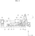
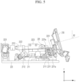
- FIGS. 4 to 7 are diagrams for explaining a method of adjusting the height of a front display 210 in a display device 200 according to an embodiment of the present disclosure.
- FIG. 8 is a diagram for explaining a method of detecting the height of a front display 210 through a position detection sensor 226 in a display device 200 according to the embodiment of the present disclosure.
- FIGS. 4 to 7 show that the height of the front display 210 is adjusted by the operation of a drive module 220 and the height of the front display 210 changes from the lowest point to the highest point.
- FIG. 4 shows a case where the height of the front display 210 is at the lowest point, and in this case, the front view of a driver or passenger may be maximized.
- the height of the front display 210 may be adjusted depending on the position of a specific facial portion of the driver through the camera 140 described above in FIG. 3 .
- a ball screw bolt 2222 may rotate by the operation of a drive motor 2221.
- a ball screw nut 2223 may move in a straight line by the rotation of the ball screw bolt 2222.
- a rotation plate 225 extending from the outer peripheral surface of a rotation shaft 224 may be rotatably coupled to the side of the ball screw nut 2223. Thus, when the ball screw nut 2223 moves linearly, the rotation plate 225 may rotate together with the rotation shaft 224.
- a first rotation protrusion 2111 formed on one side of the support bracket 211 may be inserted into a first guide groove 2211a formed on the first link 2211.
- the fixed bracket 223 may include a guide plate 2231 into which the first rotation protrusion 2111 is inserted.
- a second rotation protrusion 2112 may be formed on the other side of the support bracket 211.
- the second rotation protrusion 2112 may be inserted into one side of a second link 2212.
- the other side of second link 2212 may be rotatably coupled to the fixed bracket 223.
- the first link 2211 may include the first guide groove 2211a formed longitudinally at one side thereof.
- the first rotation protrusion 2111 may be inserted into the first guide groove 2211a.
- the guide plate 2231 may include a second guide groove 2231a having a curved shape. The first rotation protrusion 2111 is inserted into the second guide groove 2231a.
- the rotation of the ball screw bolt 2222 and the linear movement of the ball screw nut 2223 are driven by the drive motor 2221.
- the rotation of the ball screw bolt 2222 and the linear movement of the ball screw nut 2223 may rotate the first link 2211 and the second link 2212, enabling the support bracket 211 to move and thus adjusting the height of the front display 210.
- the front display 210 while the front display 210 is moving, the front display 210 also needs to rotate to align with the position of the specific facial portion of the driver.
- the angles of ⁇ 1, ⁇ 2, ⁇ 3, and ⁇ 4 shown in FIGS. 4 to 7 may all be different.
- the angles of ⁇ 1, ⁇ 2, ⁇ 3, and ⁇ 4 may be associated with the movement of the ball screw nut 2223.
Landscapes
- Engineering & Computer Science (AREA)
- Chemical & Material Sciences (AREA)
- Combustion & Propulsion (AREA)
- Transportation (AREA)
- Mechanical Engineering (AREA)
- Fittings On The Vehicle Exterior For Carrying Loads, And Devices For Holding Or Mounting Articles (AREA)
Abstract
Description
- The present disclosure relates to a display device for adjusting a height thereof depending on a position of a specific facial portion of a driver in a vehicle and control method thereof.
- A center fascia display of a vehicle may display various visual information about the vehicle. Such a display device may also be installed on a dashboard of a vehicle disposed in front of a driver's seat and a front passenger seat, and provides various convenience information such as navigation, vehicle management and operation, Internet, and entertainment.
- With the digitization of vehicles, various convenience information is being provided through diverse communication functions. For example, the location of a vehicle is checked remotely via the Internet or a smartphone, and nearby charging stations are discovered. In addition, all information on the current state of the vehicle is monitored in real time. For example, battery charging or pre-conditioning is capable of being easily activated with just a touch of a button. Moreover, intelligent driving assistance systems acquire information on road travel, thereby creating a more convenient driving environment for drivers.
- Recently, display devices mounted on vehicles are becoming larger, and thus, there is a need for means to effectively display various convenience information.
- Furthermore, there is an increasing demand for the manipulation and operation of display devices capable of providing more effective usability to drivers and passengers.
- This Summary is provided to introduce a selection of concepts in simplified form that are further described below in the Detailed Description. This Summary is not intended to identify key features or essential features of the claimed subject matter, nor is it intended to be used as an aid in determining the scope of the claimed subject matter.
- Accordingly, the present disclosure is directed to a display device and control method thereof that substantially obviate one or more problems due to limitations and disadvantages of the related art.
- The present disclosure aims to provide a display device and control method thereof. Specifically, the present disclosure aims to provide a display device for effectively providing various convenience information by adjusting the position (e.g., height) of a display depending on the position of a specific facial portion of a driver and control method thereof.
- The present disclosure aims to provide a display device for efficiently controlling the movement and tilting of a display through a drive module including a ball screw member and a link member and control method thereof.
- The present disclosure aims to provide a display device for organically controlling the movement of a display through a four-bar linkage structure involving four rotation points formed on a first link, a second link, and a support bracket and control method thereof.
- It will be appreciated by persons skilled in the art that the objects that could be achieved with the present disclosure are not limited to what has been particularly described hereinabove and the above and other objects that the present disclosure could achieve will be more clearly understood from the following detailed description.
- In a general aspect of the disclosure, a display device for a vehicle, includes: a front display positioned in front of a driver seat and a passenger seat of the vehicle; and a drive module linked to a camera installed in the vehicle and configured to adjust a position of the front display based on a position of a specific facial portion of an occupant in the driver seat or the passenger seat, wherein the drive module is configured to provide a driving force to enable movement of the front display.
- The display device may further include a support bracket coupled to a rear surface of the front display, and the drive module may include: a link member rotatably coupled to the support bracket; and a ball screw member connected to the link member and configured to move in a straight line and rotate the link member.
- The support bracket may include: a first rotation protrusion formed on a first side thereof; and a second rotation protrusion formed on a second side thereof, wherein the link member includes: a first link into which the first rotation protrusion is inserted on a first side thereof, wherein the first link comprises a first guide groove formed longitudinally; and a second link into which the second rotation protrusion is inserted on the first side thereof.
- The drive module may further include a fixed bracket formed to rotatably couple a second side of the first link and a second side of the second link.
- The fixed bracket may include a guide plate having formed thereon a second guide groove into which the first rotation protrusion is inserted, and the second guide groove may guide a curved movement of the support bracket.
- The drive module may further include: a rotation shaft coupled to the second side of the first link; and a rotation plate extending from an outer peripheral surface of the rotation shaft and coupled to the ball screw member.
- The ball screw member may include: a drive motor; a ball screw bolt configured to rotate based on an operation of the drive motor; and a ball screw nut configured to move in a straight line based on the rotation of the ball screw bolt.
- The drive module may include a position sensor to detect the position of the front display.
- The position of the front display may include a height of the display.
- The movement of the front display may include at least one of a linear movement, a rotational movement, a movement in a curved path, or any combination thereof.
- In another general aspect of the disclosure, a method of controlling a position of a display device for a vehicle, includes: recognizing a position of a specific facial portion of an occupant in a driver seat or a front passenger seat of the vehicle by a camera installed in the vehicle; determining an operation amount of movement for a ball screw member of a drive module based on the recognized position of the specific facial portion; and adjusting a position of a front display located in front of the driver seat and the passenger seat of the vehicle by rotating a link member of a drive module based on an operation of the ball screw member.
- The method may further include: receiving an operation signal from the occupant to adjust the position of the front display; and readjusting the position of the front display based on to the received operation signal.
- The position of the front display may include a height of the display.
- The movement of the front display may include at least one of a linear movement, a rotational movement, a movement in a curved path, or any combination thereof.
- The operation signal from the driver or the a passenger may be actuated by a touch on a screen of the display.
- The display may be automatically adjusted by the operation signal that is based on detection of the position of the specific facial portion of the driver or the passenger by the camera.
- In yet another general aspect of the disclosure, a system for adjusting a position of a display device in a vehicle, includes: a front display located in front of a driver seat and a passenger seat of the vehicle; a camera configured to detect a position of a specific facial portion of an occupant in the driver seat or the passenger seat; a drive module in communication with the camera and configured to provide a driving force to enable movement of the front display; a processor configured to control the drive module to adjust a position of the front display to provide optimal viewing by the occupant.
- The movement of the front display may include at least one of a linear movement, a rotational movement, a movement in a curved path, or any combination thereof.
- The accompanying drawings, which are included to provide a further understanding of the disclosure and are incorporated in and constitute a part of this application, illustrate embodiment(s) of the disclosure and together with the description serve to explain the principle of the disclosure. In the drawings:
-
FIG. 1 is a diagram illustrating a vehicle according to an embodiment of the present disclosure; -
FIG. 2 is a perspective view of a display device according to an embodiment of the present disclosure; -
FIG. 3 is a diagram for explaining a method of recognizing the position of a specific facial portion of a driver in a display device according to an embodiment of the present disclosure; -
FIGS. 4 to 7 are diagrams for explaining a method of adjusting the height of a front display in a display device according to an embodiment of the present disclosure; -
FIG. 8 is a diagram for explaining a method of detecting the height of a front display through a position detection sensor in a display device according to the embodiment of the present disclosure; -
FIG. 9 is a diagram for explaining a method of controlling a display device according to an embodiment of the present disclosure; and -
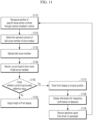
FIGS. 10 and11 are diagrams for explaining various embodiments of a display device control method according to the present disclosure. - Description will now be given in detail according to exemplary embodiments disclosed herein, with reference to the accompanying drawings. The same or equivalent components may be provided with the same reference numbers, and description thereof will not be repeated. As used herein, the suffixes "module" and "part" are added or used interchangeably to facilitate preparation of this specification and are not intended to suggest distinct meanings or functions. In describing embodiments disclosed in this specification, relevant well-known technologies may not be described in detail in order not to obscure the subject matter of the embodiments disclosed in this specification. In addition, it should be noted that the accompanying drawings are only for easy understanding of the embodiments disclosed in the present specification, and should not be construed as limiting the technical spirit disclosed in the present specification. As such, the present disclosure should be construed to extend to any alterations, equivalents and substitutes in addition to those which are particularly set out in the accompanying drawings.
- Although the terms first, second, etc. may be used herein to describe various elements, these elements should not be limited by these terms. These terms are generally only used to distinguish one element from another.
- It will be understood that when an element is referred to as being "connected with" another element, the element can be directly connected with the other element or intervening elements may also be present. In contrast, it will be understood that when an element is referred to as being "directly connected with" another element, there are no intervening elements present.
- A singular representation may include a plural representation unless it represents a definitely different meaning from the context.
- The terms such as "include" or "have" used herein are intended to indicate that features, numbers, steps, operations, elements, components, or combinations thereof used in the following description exist and it should be thus understood that the possibility of existence or addition of one or more different features, numbers, steps, operations, elements, components, or combinations thereof is not excluded.
-
FIG. 1 is a diagram illustrating avehicle 100 according to an embodiment of the present disclosure.FIG. 2 is a perspective view of adisplay device 200 according to an embodiment of the present disclosure.FIG. 3 is a diagram for explaining a method of recognizing the position of a specific facial portion of adriver 10 in adisplay device 200 according to an embodiment of the present disclosure. - Hereinafter, in describing the
display device 200 according to the embodiment of the present disclosure, it is assumed that the front and rear direction is the x-axis direction, the left and right direction is the y-axis direction, and the up and down direction is the z-axis direction. -
FIG. 1 is a diagram illustrating thevehicle 100 according to the embodiment of the present disclosure. Specifically,FIG. 1 shows the front of a driver seat and a front passenger seat inside thevehicle 100. - As shown in
FIG. 1 , thedisplay device 200 may be mounted on a mountingportion 120 located on avehicle body 110. The mountingportion 120 may include a dashboard positioned in front of the driver seat and front passenger seat. In addition, thedisplay device 200 may include afront display 210 positioned in front of the driver seat and front passenger seat of thevehicle 100. As illustrated inFIG. 2 , thedisplay device 200 may include adrive module 220 for adjusting the height of thefront display 210. - In addition, a
steering wheel 130 may be positioned in front of the driver seat. Thesteering wheel 130 mounted on thevehicle 100 according to the embodiment of the present disclosure may include a D-shapedsteering wheel 130 to secure a better view of the driver towards thefront display 210. Acamera 140 may be positioned on the top of the mountingportion 120 orvehicle body 110. - The
camera 140 mounted on thevehicle 100 may play a role in recognizing the position of the specific facial portion of the driver. Thedrive module 220 is linked to thecamera 140 and configured to adjust the height of thefront display 210 depending on the position of the specific facial portion of the driver. - Referring to
FIG. 3 , thedisplay device 200 according to the embodiment of the present disclosure may recognize the position of the specific facial portion (e.g., eyes or nose) of thedriver 10 through thecamera 140. In an embodiment, while thedriver 10 is sitting on the seat, the position of the specific facial portion of thedriver 10 may be recognized within a range shown inFIG. 3 based on a height value, which is a z-axis coordinate value. - Additionally, in the
vehicle 100 according to the embodiment of the present disclosure, apassenger airbag 150 may be installed on an upper front portion of the passenger seat in response to enlargement of thedisplay device 200 and adjustment of the height of thefront display 210, which will be described later. Accordingly, the present disclosure may promote the safety of passengers as well as provide thedisplay device 200 customized for the passengers. -
FIG. 2 is a perspective view of adisplay device 200 according to an embodiment of the present disclosure. - The
display device 200 according to the embodiment of the present disclosure may include adrive module 220 that is linked to afront display 210 positioned in front of a driver seat and a passenger seat of avehicle 100 and acamera 140 mounted on thevehicle 100 and configured to adjust the height of thefront display 210 depending on the position of a specific facial portion of a driver. Thedrive module 220 may provide driving force to thefront display 210 to allow thefront display 210 to rotate and move in a curved path. - A
support bracket 211 may be coupled to the rear surface of thefront display 210. Thedrive module 220 may include alink member 221 rotatably coupled to thesupport bracket 211. Thedrive module 220 may include aball screw member 222 that is connected to thelink member 221, moves in a straight line, and rotates thelink member 221. - The
support bracket 211 may include afirst rotation protrusion 2111 formed on one side thereof and asecond rotation protrusion 2112 formed on the other side thereof. Thelink member 221 may include afirst link 2211 into which thefirst rotation protrusion 2111 is inserted on one side thereof and asecond link 2212 into which thesecond rotation protrusion 2112 is inserted on the one side thereof. In particular, thefirst link 2211 may include afirst guide groove 2211a formed longitudinally. - The
drive module 220 may include a fixedbracket 223 formed to rotatably couple the other side of thefirst link 2211 and the other side of thesecond link 2212. The fixedbracket 223 may include aguide plate 2231 into which thefirst rotation protrusion 2111 is inserted. In particular, theguide plate 2231 may include asecond guide groove 2231a formed to guide the curved movement of thesupport bracket 211. - The
drive module 220 may include arotation plate 225. Therotation plate 225 is formed by extending from arotation shaft 224 coupled to the other side of thefirst link 2211 and the outer peripheral surface of therotation shaft 224. In addition, therotation plate 225 is coupled to theball screw member 222. Asecond rotation shaft 228 may be coupled to the other side of thesecond link 2212. Therefore, a pair oflink members 221 may be rotated simultaneously through therotation shaft 224. - The
ball screw member 222 may include adrive motor 2221, aball screw bolt 2222, and aball screw nut 2223. Theball screw bolt 2222 rotates when driven by thedrive motor 2221, and theball screw nut 2223 moves linearly due to the rotation of theball screw bolt 2222. In this case, therotation plate 225 may be rotatably coupled to theball screw nut 2223. Therefore, as theball screw nut 2223 moves in a straight line, therotation plate 225 may rotate with therotation shaft 224, enabling the rotation of thefirst link 2211. - Additionally, the
display device 200 according to the embodiment of the present disclosure may include aposition detection sensor 226 that detects the height of thefront display 210. Thedrive module 220 may include adetection plate 227 that extends from the outer peripheral surface of therotation shaft 224 at a position corresponding to theposition detection sensor 226. - Hereinafter, a method of operating the components included in the
display device 200 according to the embodiment of the present disclosure will be described in more detail. -
FIGS. 4 to 7 are diagrams for explaining a method of adjusting the height of afront display 210 in adisplay device 200 according to an embodiment of the present disclosure.FIG. 8 is a diagram for explaining a method of detecting the height of afront display 210 through aposition detection sensor 226 in adisplay device 200 according to the embodiment of the present disclosure. - Specifically,
FIGS. 4 to 7 show that the height of thefront display 210 is adjusted by the operation of adrive module 220 and the height of thefront display 210 changes from the lowest point to the highest point. -
FIG. 4 shows a case where the height of thefront display 210 is at the lowest point, and in this case, the front view of a driver or passenger may be maximized. In this state, the height of thefront display 210 may be adjusted depending on the position of a specific facial portion of the driver through thecamera 140 described above inFIG. 3 . - Specifically, a
ball screw bolt 2222 may rotate by the operation of adrive motor 2221. Aball screw nut 2223 may move in a straight line by the rotation of theball screw bolt 2222. Arotation plate 225 extending from the outer peripheral surface of arotation shaft 224 may be rotatably coupled to the side of theball screw nut 2223. Thus, when theball screw nut 2223 moves linearly, therotation plate 225 may rotate together with therotation shaft 224. - A
support bracket 211, which is coupled to the rear surface of thefront display 210, may be rotatably coupled to one side of afirst link 2211. Therotation shaft 224 may be coupled to the other side of thefirst link 2211. In addition, the other side of thefirst link 2211 may be rotatably coupled to a fixedbracket 223. - A
first rotation protrusion 2111 formed on one side of thesupport bracket 211 may be inserted into afirst guide groove 2211a formed on thefirst link 2211. The fixedbracket 223 may include aguide plate 2231 into which thefirst rotation protrusion 2111 is inserted. - A
second rotation protrusion 2112 may be formed on the other side of thesupport bracket 211. Thesecond rotation protrusion 2112 may be inserted into one side of asecond link 2212. The other side ofsecond link 2212 may be rotatably coupled to the fixedbracket 223. - In particular, the
first link 2211 may include thefirst guide groove 2211a formed longitudinally at one side thereof. Thefirst rotation protrusion 2111 may be inserted into thefirst guide groove 2211a. Theguide plate 2231 may include asecond guide groove 2231a having a curved shape. Thefirst rotation protrusion 2111 is inserted into thesecond guide groove 2231a. - Therefore, the rotation of the
ball screw bolt 2222 and the linear movement of theball screw nut 2223 are driven by thedrive motor 2221. The rotation of theball screw bolt 2222 and the linear movement of theball screw nut 2223 may rotate thefirst link 2211 and thesecond link 2212, enabling thesupport bracket 211 to move and thus adjusting the height of thefront display 210. - In particular, as described above, while the
front display 210 is moving, thefront display 210 also needs to rotate to align with the position of the specific facial portion of the driver. In other words, to align with the position of the specific facial portion of the driver, the angles of θ1, θ2, θ3, and θ4 shown inFIGS. 4 to 7 may all be different. The angles of θ1, θ2, θ3, and θ4 may be associated with the movement of theball screw nut 2223. - In addition, due to the structure in which the
front display 210 is inserted and mounted into the mountingportion 120 of thevehicle 100 described above, it is necessary to protect a front lower part of thefront display 210 while thefront display 210 is moving. - To this end, the
display device 200 according to the embodiment of the present disclosure may enable thefront display 210 to rotate and move in a curved path during the movement of thefront display 210. This may be implemented through thesecond guide groove 2231a, which is formed with a curved shape in theguide plate 2231, and thefirst guide groove 2211a, which is formed longitudinally at one end of thefirst link 2211. - That is, the
first rotation protrusion 2111 formed on thesupport bracket 211 may be inserted into thefirst guide groove 2211a and thesecond guide groove 2231a, allowing thesupport bracket 211 to rotate and move in a curved path when thefirst link 2211 rotates. - Therefore, in the
display device 200 according to the embodiment of the present disclosure, thedrive module 220 may adjust the height of thefront display 210 through a four-bar linkage structure involving four rotation points formed on thefirst link 2211,second link 2212, andsupport bracket 211. - Additionally, the
front display 210 may rotate and move in a curved path to align with the specific facial portion of the driver and to protect the front lower part of thefront display 210. - Referring to
FIG. 8 , in thedisplay device 200 according to the embodiment of the present disclosure, adrive module 220 may include theposition detection sensor 226 that detects the height of thefront display 210. - In an embodiment, the
position detection sensor 226 may be located at the top of a fixedbracket 223. Thedrive module 220 may include adetection plate 227 extending from the outer peripheral surface of arotation shaft 224 at a position corresponding to theposition detection sensor 226. Therefore, thedetection plate 227 may rotate together with therotation shaft 224, and theposition detection sensor 226 may detect the height of thefront display 210 by detecting a change in the position depending on the rotation of thedetection plate 227. -
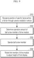
FIG. 9 is a diagram for explaining a method of controlling a display device according to an embodiment of the present disclosure.FIGS. 10 and11 are diagrams for explaining various embodiments of a display device control method according to the present disclosure. - Hereinafter, the display device control method according to the embodiment of the present disclosure will be described based on the content described above with reference to
FIGS. 1 to 8 . - In the display device control method according to the embodiment of the present disclosure, the position of a specific facial portion of a driver may be recognized through a
camera 140 mounted on a vehicle 100 (S910). Then, the operation amount of aball screw member 222 of adrive module 220 may be determined based on the recognized position of the specific facial portion (S920). Here, the operation amount of theball screw member 222 may refer to the movement amount of aball screw nut 2223 when theball screw nut 2223 moves in a straight line. Accordingly, the rotation amount of theball screw bolt 2222 through the operation of adrive motor 2221 may be determined. - Through the operation of the ball screw member 222 (S930), a
link member 221 of thedrive module 220 may rotate, thereby adjusting the height of a front display 210 (S940). In particular, the display device control method according to the embodiment of the present disclosure may adjust the height of thefront display 210 to align with the position of the specific facial portion of the driver and control thefront display 210 to rotate and move in a curved path to protect a front lower part of thefront display 210. -
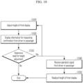
FIG. 10 is a diagram for explaining another embodiment of the display device control method according to the present disclosure. - After adjustment of the height of a front display 210 (S1010), information for requesting confirmation from a driver or passenger may be displayed (S1020). The information for requesting confirmation from the driver or passenger may be displayed on the screen of the
front display 210, and the displayed information for requesting confirmation may include, for example, whether adjustment of the height of thefront display 210 is necessary as shown inFIG. 10 (S1030). - If the driver or passenger determines that the height adjustment is not necessary, the adjusted height of the
front display 210 may be maintained. On the other hand, if the driver or passenger determines that the height adjustment is necessary, an operation signal from the driver or passenger may be received (S1040). The operation signal from the driver or passenger may include, for example, adjusting the height of thefront display 210 through a touch on the screen of thefront display 210. In addition, based on the operation signal from the driver or passenger, the height of thefront display 210 may be readjusted (S1050). Additionally, the display may be automatically adjusted by an operation signal that is based on detection of a position of a specific facial portion of the driver or the front passenger by thecamera 140. - Alternatively, the displayed information for requesting confirmation may include information for proceeding to the step of adjusting the height of the front display 210 (S1010). The driver or passenger may initiate the height adjustment step (S1010) again by touching the screen of the
front display 210. -
FIG. 11 is a diagram for explaining a further embodiment of the display device control method according to the present disclosure. - After recognizing the position of a specific facial portion of a driver through a
camera 140 mounted on a vehicle 100 (S1110), the operation amount of aball screw member 222 of adrive module 220 may be determined depending on the position of the recognized specific facial portion (S1120). Theball screw member 222 may operate based thereon (S1130). - In this case, a current load of the
drive motor 2221 of theball screw member 222 may be monitored (S1140), and it may be determined whether the monitored current load exceeds a reference value (S1150). This is because, if the operation of thedrive module 220 is obstructed by obstacles, it may lead to damage of thedisplay device 200. If the monitored current load does not exceed the reference value, the operation of theball screw member 222 may continue, allowing the height of afront display 210 to be adjusted (S1160). - On the other hand, if the monitored current load exceeds the reference value, that is, if the operation of the
drive module 220 is obstructed by obstacles, thefront display 210 may be returned to the original position (S1170). Thereafter, information for requesting confirmation of obstacles may be displayed (S1180). The information for requesting confirmation of obstacles may be displayed on the screen of thefront display 210. In addition, an operation signal from the driver or passenger may be received (S1190). - The operation signal from the driver or passenger may be received, for example, through a touch on the screen of the
front display 210. After removing any obstacles that obstruct the operation of thedrive module 220, the driver or passenger may send the operation signal to enable thedrive module 220 to operate again through the touch on the screen of thefront display 210. Thereafter, the display device control method may return to the step of recognizing the position of the specific facial portion of the driver through thecamera 140 mounted on the vehicle 100 (S1110). - The present disclosure further includes a system for adjusting a position of a display device in a vehicle. The system includes: the
front display 210 that is located in front of a driver seat and a passenger seat of thevehicle 100; thecamera 140 configured to detect a position of a specific facial portion of an occupant in the driver seat or the passenger seat; thedrive module 220 that is in communication with thecamera 140 and configured to provide a driving force to enable movement of thefront display 210; a controller (e.g., a processor) configured to control thedrive module 220 to adjust a position of thefront display 210 to provide optimal viewing by the occupant. The movement of thefront display 210 includes at least one of a linear movement, a rotational movement, a movement in a curved path, or any combination thereof. - In summary, the display device and control method thereof according to the present disclosure may adjust the height of the display depending on the position of the specific facial portion of the driver, thereby effectively providing various convenience information. Additionally, the display device and control method thereof according to the present disclosure may efficiently control the movement and tilting of the display through the drive module including the ball screw member and the link member.
Claims (15)
- A display device for a vehicle, the display device comprising:a front display positioned in front of a driver seat and a passenger seat of the vehicle; anda drive module linked to a camera installed in the vehicle and configured to adjust a position of the front display based on a position of a specific facial portion of an occupant in the driver seat or the passenger seat,wherein the drive module is configured to provide a driving force to enable movement of the front display.
- The display device of claim 1, further comprising:a support bracket coupled to a rear surface of the front display,wherein the drive module comprises:a link member rotatably coupled to the support bracket; anda ball screw member connected to the link member and configured to move in a straight line and rotate the link member.
- The display device of claim 2, wherein the support bracket comprises:a first rotation protrusion formed on a first side thereof; anda second rotation protrusion formed on a second side thereof,wherein the link member comprises:a first link into which the first rotation protrusion is inserted on a first side thereof, wherein the first link comprises a first guide groove formed longitudinally; anda second link into which the second rotation protrusion is inserted on the first side thereof.
- The display device of claim 3, wherein the drive module further comprises a fixed bracket formed to rotatably couple a second side of the first link and a second side of the second link.
- The display device of claim 4,wherein the fixed bracket comprises a guide plate having formed thereon a second guide groove into which the first rotation protrusion is inserted, andwherein the second guide groove is configured to guide a curved movement of the support bracket.
- The display device of claim 4, or 5, wherein the drive module further comprises:a rotation shaft coupled to the second side of the first link; anda rotation plate extending from an outer peripheral surface of the rotation shaft and coupled to the ball screw member.
- The display device of any one of claims 2 to 6, wherein the ball screw member comprises:a drive motor;a ball screw bolt configured to rotate based on an operation of the drive motor; anda ball screw nut configured to move in a straight line based on the rotation of the ball screw bolt.
- The display device of any one of claims 1 to 7, wherein the drive module comprises a position sensor configured to detect the position of the front display.
- The display device of any one of claims 1 to 8, wherein the position of the front display comprises a height of the display.
- The display device of any one of claims 1 to 9, wherein the movement of the front display includes at least one of a linear movement, a rotational movement, a movement in a curved path, or any combination thereof.
- A method of controlling a position of a display device for a vehicle, the method comprising:recognizing a position of a specific facial portion of an occupant in a driver seat or a front passenger seat of the vehicle by a camera installed in the vehicle;determining an operation amount of movement for a ball screw member of a drive module based on the recognized position of the specific facial portion; andadjusting a position of a front display located in front of the driver seat and the passenger seat of the vehicle by rotating a link member of a drive module based on an operation of the ball screw member.
- The method of claim 11, comprising:receiving an operation signal from the occupant to adjust the position of the front display; andreadjusting the position of the front display based on to the received operation signal.
- The method of claim 12, wherein the operation signal from the driver or the a passenger is actuated by a touch on a screen of the display.
- The method of claim 12, or 13, wherein the display is automatically adjusted by the operation signal that is based on detection of the position of the specific facial portion of the driver or the passenger by the camera.
- A system for adjusting a position of a display device in a vehicle, the system comprising:a front display located in front of a driver seat and a passenger seat of the vehicle;a camera configured to detect a position of a specific facial portion of an occupant in the driver seat or the passenger seat;a drive module in communication with the camera and configured to provide a driving force to enable movement of the front display;a processor configured to control the drive module to adjust a position of the front display to provide optimal viewing by the occupant.
Applications Claiming Priority (1)
| Application Number | Priority Date | Filing Date | Title |
|---|---|---|---|
| KR1020230194169A KR20250102479A (en) | 2023-12-28 | 2023-12-28 | Display device and control method thereof |
Publications (1)
| Publication Number | Publication Date |
|---|---|
| EP4578694A1 true EP4578694A1 (en) | 2025-07-02 |
Family
ID=92295931
Family Applications (1)
| Application Number | Title | Priority Date | Filing Date |
|---|---|---|---|
| EP24193482.7A Pending EP4578694A1 (en) | 2023-12-28 | 2024-08-08 | Display device and control method thereof |
Country Status (4)
| Country | Link |
|---|---|
| US (1) | US12589654B2 (en) |
| EP (1) | EP4578694A1 (en) |
| KR (1) | KR20250102479A (en) |
| CN (1) | CN120229101A (en) |
Families Citing this family (1)
| Publication number | Priority date | Publication date | Assignee | Title |
|---|---|---|---|---|
| GB202410371D0 (en) * | 2024-07-16 | 2024-08-28 | Agco Int Gmbh | Control unit for display adaption |
Citations (4)
| Publication number | Priority date | Publication date | Assignee | Title |
|---|---|---|---|---|
| DE102016009989A1 (en) * | 2016-08-17 | 2017-02-16 | Daimler Ag | Adjustment device for adjusting at least one display and / or operating element of a motor vehicle |
| US20170098425A1 (en) * | 2015-10-06 | 2017-04-06 | Yazaki Corporation | Vehicle display apparatus |
| DE102023000349A1 (en) * | 2023-02-06 | 2023-03-23 | Mercedes-Benz Group AG | Display device with a bend-adjustable display unit for a vehicle |
| DE102021214768A1 (en) * | 2021-12-21 | 2023-06-22 | Robert Bosch Gesellschaft mit beschränkter Haftung | Device for moving a display surface |
Family Cites Families (40)
| Publication number | Priority date | Publication date | Assignee | Title |
|---|---|---|---|---|
| US20100262336A1 (en) * | 2009-04-09 | 2010-10-14 | Qualcomm Incorporated | System and method for generating and rendering multimedia data including environmental metadata |
| US11935281B2 (en) * | 2010-06-07 | 2024-03-19 | Affectiva, Inc. | Vehicular in-cabin facial tracking using machine learning |
| US20180182261A1 (en) * | 2014-07-02 | 2018-06-28 | Iotmotive Ltd. | Real Time Car Driving Simulator |
| US10723267B2 (en) * | 2014-09-19 | 2020-07-28 | Be Topnotch, Llc | Display rear passenger view on a display screen in vehicle |
| US9942522B2 (en) * | 2015-08-19 | 2018-04-10 | Faraday&Future Inc. | In-vehicle camera system |
| US10583709B2 (en) * | 2016-11-11 | 2020-03-10 | International Business Machines Corporation | Facilitating personalized vehicle occupant comfort |
| US10099598B2 (en) * | 2016-12-30 | 2018-10-16 | Michael H Gurin | Reconfigurable shared use vehicle |
| US20190047498A1 (en) * | 2018-01-12 | 2019-02-14 | Intel Corporation | Adaptive display for preventing motion sickness |
| EP3714340A4 (en) * | 2018-01-31 | 2021-03-31 | Xirgo Technologies, LLC | Enhanced vehicle sharing system |
| US11807183B2 (en) * | 2018-10-23 | 2023-11-07 | Ts Tech Co., Ltd. | Occupant protection apparatus |
| US20200238952A1 (en) * | 2019-01-28 | 2020-07-30 | Jeffrey Dean Lindsay | Facial recognition systems for enhanced security in vehicles and other devices |
| JP7112347B2 (en) * | 2019-02-08 | 2022-08-03 | 本田技研工業株式会社 | VEHICLE CONTROL DEVICE, VEHICLE CONTROL METHOD, VEHICLE AND PROGRAM |
| US11110821B2 (en) * | 2019-02-11 | 2021-09-07 | Byton North America Corporation | Sliding center module system for vehicle |
| JP6933677B2 (en) * | 2019-03-07 | 2021-09-08 | 本田技研工業株式会社 | Vehicle control devices, vehicle control methods, vehicles and programs |
| JP6852107B2 (en) * | 2019-03-19 | 2021-03-31 | 本田技研工業株式会社 | Vehicle control devices, vehicle control methods, vehicles and programs |
| JP7191752B2 (en) * | 2019-03-27 | 2022-12-19 | 本田技研工業株式会社 | Vehicle control system and vehicle |
| JP7183943B2 (en) * | 2019-05-09 | 2022-12-06 | トヨタ自動車株式会社 | steering module |
| US11752872B2 (en) * | 2019-06-07 | 2023-09-12 | Ford Global Technologies, Llc | Interior vehicle component |
| US20200410790A1 (en) * | 2019-06-27 | 2020-12-31 | Toyota Motor Engineering & Manufacturing North America, Inc. | Camera system and sensors for vehicle |
| US11787288B2 (en) * | 2019-07-24 | 2023-10-17 | Harman International Industries, Incorporated | Systems and methods for user interfaces in a vehicular environment |
| KR20210082316A (en) * | 2019-12-24 | 2021-07-05 | 삼성디스플레이 주식회사 | Display panel and display device including the same |
| US11625937B2 (en) * | 2020-04-06 | 2023-04-11 | Toyota Motor Engineering & Manufacturing North America, Inc. | Methods and systems for monitoring human body weight with vehicle sensors and big data AI analytics |
| JP7332535B2 (en) * | 2020-05-27 | 2023-08-23 | 本田技研工業株式会社 | Vehicle control system, server, and vehicle control method |
| EP4163764A4 (en) * | 2020-07-03 | 2023-11-22 | Huawei Technologies Co., Ltd. | In-vehicle air gesture interaction method, electronic device, and system |
| US12479521B2 (en) * | 2020-08-11 | 2025-11-25 | ScooterBug, Inc. | Wireless network, systems and methods for configuration, operation and use of motorized, wheeled and steerable passenger-carrying carts for entertainment purposes |
| US12086308B2 (en) * | 2021-01-20 | 2024-09-10 | Magna Electronics Inc. | Vehicular driver assist system with adjustable display |
| WO2022187805A1 (en) * | 2021-03-01 | 2022-09-09 | Magna Mirrors Of America, Inc. | Interior rearview mirror assembly with driver monitoring system |
| US12202337B2 (en) * | 2021-04-02 | 2025-01-21 | Toyota Jidosha Kabushiki Kaisha | Display device for vehicle |
| WO2022241638A1 (en) * | 2021-05-18 | 2022-11-24 | 华为技术有限公司 | Projection method and apparatus, and vehicle and ar-hud |
| US20230022436A1 (en) * | 2021-07-21 | 2023-01-26 | Indiev, Inc | Forward facing rear vehicle video system |
| US12031374B2 (en) * | 2021-08-17 | 2024-07-09 | Ford Global Technologies, Llc | Vehicle having imaging device for driver and window monitoring |
| JP7524865B2 (en) * | 2021-08-18 | 2024-07-30 | トヨタ自動車株式会社 | Seat control device, method and program |
| JP7493546B2 (en) * | 2022-03-30 | 2024-05-31 | 本田技研工業株式会社 | Safety Support Devices |
| US12091058B2 (en) * | 2022-06-20 | 2024-09-17 | International Business Machines Corporation | Virtual steering wheel with autonomous vehicle |
| US12010461B2 (en) * | 2022-06-24 | 2024-06-11 | GM Global Technology Operations LLC | Multimedia system for a scalable infotainment system of a motor vehicle |
| US12026306B2 (en) * | 2022-07-28 | 2024-07-02 | Rivian Ip Holdings, Llc | Systems and methods for displaying information on a driver's display |
| JP2024041343A (en) * | 2022-09-14 | 2024-03-27 | 本田技研工業株式会社 | Information processing device, information processing system, and information processing method |
| US12479363B2 (en) * | 2023-01-17 | 2025-11-25 | Rivian Ip Holdings, Llc | Rear display enhancements |
| US20240246412A1 (en) * | 2023-01-20 | 2024-07-25 | ShareSafe Media, LLC | System and method for controlling content presented on displays within vehicles using a mobile computing device |
| US12128822B1 (en) * | 2023-05-24 | 2024-10-29 | Ford Global Technologies, Llc | Vehicle having selectable lighting environment and method |
-
2023
- 2023-12-28 KR KR1020230194169A patent/KR20250102479A/en active Pending
-
2024
- 2024-07-15 US US18/772,704 patent/US12589654B2/en active Active
- 2024-08-08 EP EP24193482.7A patent/EP4578694A1/en active Pending
- 2024-08-27 CN CN202411185201.3A patent/CN120229101A/en active Pending
Patent Citations (4)
| Publication number | Priority date | Publication date | Assignee | Title |
|---|---|---|---|---|
| US20170098425A1 (en) * | 2015-10-06 | 2017-04-06 | Yazaki Corporation | Vehicle display apparatus |
| DE102016009989A1 (en) * | 2016-08-17 | 2017-02-16 | Daimler Ag | Adjustment device for adjusting at least one display and / or operating element of a motor vehicle |
| DE102021214768A1 (en) * | 2021-12-21 | 2023-06-22 | Robert Bosch Gesellschaft mit beschränkter Haftung | Device for moving a display surface |
| DE102023000349A1 (en) * | 2023-02-06 | 2023-03-23 | Mercedes-Benz Group AG | Display device with a bend-adjustable display unit for a vehicle |
Also Published As
| Publication number | Publication date |
|---|---|
| US20250214438A1 (en) | 2025-07-03 |
| KR20250102479A (en) | 2025-07-07 |
| CN120229101A (en) | 2025-07-01 |
| US12589654B2 (en) | 2026-03-31 |
Similar Documents
| Publication | Publication Date | Title |
|---|---|---|
| JP6682574B2 (en) | Method of using a communication terminal in a motor vehicle with an autopilot operating and motor vehicle | |
| US10730448B2 (en) | Vehicle display device and vehicle | |
| CN105751900B (en) | vehicle with display | |
| EP2733006B1 (en) | Vehicular display system | |
| US20130151072A1 (en) | Eye breakaway prevention system for use while driving a vehicle | |
| WO2014070886A1 (en) | System and method for using gestures in autonomous parking | |
| WO2018167945A1 (en) | Occupant protection device | |
| US20210129672A1 (en) | System and method for controlling display of vehicle | |
| US12589654B2 (en) | Display device and control method thereof | |
| EP4578695A1 (en) | Display device and vehicle equipped with same | |
| US12623734B2 (en) | Electric vehicle and balancing of an electric vehicle | |
| CN117255751A (en) | Motor vehicle with display device and method for adjusting display device | |
| KR101657656B1 (en) | Vehicle comprising display device | |
| KR20210083483A (en) | Display apparatus for vehicle | |
| CN116867664A (en) | Vehicle infotainment system | |
| CN216102343U (en) | Steering wheel and vehicle | |
| CN113597386B (en) | Infotainment device for vehicle | |
| WO2014054135A1 (en) | Vehicle navigation device | |
| JP2002178855A (en) | Equipment control equipment | |
| JP2018070029A (en) | Driving support device | |
| US20250108854A1 (en) | User interface for controlling vehicle components | |
| US12109960B2 (en) | Passenger seat control system and method | |
| EP3448723B1 (en) | Human-machine interface apparatus for a vehicle | |
| JP2006069476A (en) | In-vehicle image display pedestal | |
| EP4339001A1 (en) | Control module for a vehicle |
Legal Events
| Date | Code | Title | Description |
|---|---|---|---|
| PUAI | Public reference made under article 153(3) epc to a published international application that has entered the european phase |
Free format text: ORIGINAL CODE: 0009012 |
|
| STAA | Information on the status of an ep patent application or granted ep patent |
Free format text: STATUS: THE APPLICATION HAS BEEN PUBLISHED |
|
| AK | Designated contracting states |
Kind code of ref document: A1 Designated state(s): AL AT BE BG CH CY CZ DE DK EE ES FI FR GB GR HR HU IE IS IT LI LT LU LV MC ME MK MT NL NO PL PT RO RS SE SI SK SM TR |
|
| STAA | Information on the status of an ep patent application or granted ep patent |
Free format text: STATUS: REQUEST FOR EXAMINATION WAS MADE |
|
| 17P | Request for examination filed |
Effective date: 20251229 |
|
| STAA | Information on the status of an ep patent application or granted ep patent |
Free format text: STATUS: EXAMINATION IS IN PROGRESS |
|
| 17Q | First examination report despatched |
Effective date: 20260302 |