EP4578601A2 - Tool storage system - Google Patents
Tool storage system Download PDFInfo
- Publication number
- EP4578601A2 EP4578601A2 EP25176702.6A EP25176702A EP4578601A2 EP 4578601 A2 EP4578601 A2 EP 4578601A2 EP 25176702 A EP25176702 A EP 25176702A EP 4578601 A2 EP4578601 A2 EP 4578601A2
- Authority
- EP
- European Patent Office
- Prior art keywords
- bracket
- tool
- cleat
- storage system
- support member
- Prior art date
- Legal status (The legal status is an assumption and is not a legal conclusion. Google has not performed a legal analysis and makes no representation as to the accuracy of the status listed.)
- Pending
Links
Images




Classifications
-
- B—PERFORMING OPERATIONS; TRANSPORTING
- B25—HAND TOOLS; PORTABLE POWER-DRIVEN TOOLS; MANIPULATORS
- B25H—WORKSHOP EQUIPMENT, e.g. FOR MARKING-OUT WORK; STORAGE MEANS FOR WORKSHOPS
- B25H3/00—Storage means or arrangements for workshops facilitating access to, or handling of, work tools or instruments
- B25H3/04—Racks
-
- B—PERFORMING OPERATIONS; TRANSPORTING
- B25—HAND TOOLS; PORTABLE POWER-DRIVEN TOOLS; MANIPULATORS
- B25H—WORKSHOP EQUIPMENT, e.g. FOR MARKING-OUT WORK; STORAGE MEANS FOR WORKSHOPS
- B25H3/00—Storage means or arrangements for workshops facilitating access to, or handling of, work tools or instruments
- B25H3/003—Holders for drill bits or the like
-
- B—PERFORMING OPERATIONS; TRANSPORTING
- B25—HAND TOOLS; PORTABLE POWER-DRIVEN TOOLS; MANIPULATORS
- B25H—WORKSHOP EQUIPMENT, e.g. FOR MARKING-OUT WORK; STORAGE MEANS FOR WORKSHOPS
- B25H3/00—Storage means or arrangements for workshops facilitating access to, or handling of, work tools or instruments
- B25H3/006—Storage means specially adapted for one specific hand apparatus, e.g. an electric drill
Definitions
- the present disclosure relates to storage systems, and more particularly to wall mounted storage systems for tools and the like.
- Hand tools, power tools, and associated accessories such as batteries, tool bits, fasteners, and the like, may be moved frequently between a storage space and a work space.
- One aspect of accessibility is a user's ability to quickly store an object and remove the object from storage.
- Another aspect of accessibility is the storage system's ability to engage many objects with a standardized connection mechanism between the system and the object. This may also permit an object to engage the storage system at a plurality of locations.
- accessible storage systems provide options for accessing tools and bits with tools either directly from the storage system, or from a mobile storage system (i.e., on a tool belt) that is movable with the user between the storage system and a position adjacent a work space.
- a storage system in one independent aspect, includes a support member having a cleat thereon, a bracket engageable with the cleat, and a lever movable between a locked position and an unlocked position.
- the storage system further includes an object permitted to be coupled or uncoupled relative to the bracket while the lever is in the unlocked position, the object being secured to the bracket while the lever is in the locked position.
- a storage system is configured to support a tool.
- the support system includes a first support member having a cleat thereon, and a bracket.
- the bracket is configured to engage the cleat.
- the bracket includes a retainer configured to engage a support surface of a second support member separate from the first support member.
- the bracket is selectively coupled to the tool. While the bracket is coupled to the tool, the bracket and the tool and movable between a first position, a second position, and a third position. While in the first position, the bracket engages the cleat and supports the tool relative to the cleat. While in the second position, the bracket engages the support surface and supports the tool relative to the support surface. While in the third position, the bracket is removed from the cleat and the support surface.
- a storage system configured to support a tool.
- the storage system includes a support member having a cleat thereon and a bracket.
- the bracket is configured to engage the cleat.
- the bracket includes a bit storage member including a plurality of recesses each configured to selectively receive one of a plurality of tool bits therein.
- the bracket further includes a retainer configured to secure the bracket to the tool.
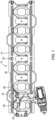
- FIG. 1 illustrates a tool storage system 10 including a support member (e.g., a panel or rail 14), a bracket 18, and an object (e.g., a tool, optionally a power tool) 22.
- the rail 14 is mounted on a wall W (i.e., a support surface) by a support fastener 23 ( FIG. 1 ).
- the illustrated rail 14 may include multiple projections or cleats 26 which project outwardly from the wall W (see FIG. 5 ) and protrude from the rail 14.
- the rail 14 may include a single cleat 26.
- the bracket 18 of the tool storage system 10 engages (i.e., is nested between) multiple cleats 26 and is supported between adjacent cleats 26.
- the bracket 18 may engage the cleats 26 in a different manner, and/or may engage a single cleat 26.
- the bracket 18 is coupled to the tool 22 for connecting the tool 22 to the rail 14.
- the rail 14 may support more than a single bracket 18 and tool 22 in a similar manner as described with respect to the illustrated bracket 18 and tool 22.
- FIG. 2 illustrates a retention mechanism 30 configured to connect the tool 22 to the bracket 18.
- the retention mechanism 30 includes a lever 34 that is supported for movement with respect to the bracket 18.
- the lever 34 is positioned at least partially within a lever receptacle 18a on the bracket 18, and is movable between a locked position (illustrated in solid lines) and an unlocked or released position (illustrated in dashed lines).
- the lever 34 may be biased toward the locked position by a biasing force and is movable to the unlocked position in response to a force exerted against the biasing force.
- the retention mechanism 30 provides a quick release retention mechanism 30 in which an operator can quickly secure and/or remove the tool 22 from the bracket 18.
- the retention mechanism 30 further includes a stud 38 which is secured to the tool 22.
- the stud 38 is located adjacent a battery receptacle 42 of the tool 22. Further, in the illustrated embodiment, the stud 38 projects laterally away from the battery receptacle 42 of the tool 22.
- the stud 38 is movable to engage the lever 34 and to provide the force exerted against the biasing force to retract the lever 34 to the unlocked position (illustrated as the lever 34'). Subsequently, the stud 38 is configured to engage the lever 34 to connect the tool 22 the lever 34.
- the bracket 18 includes an opening 18b. The opening 18b is in communication with the lever receptacle 18a.
- a user may conduct a "quick release" of the lever 34 to the unlocked position (illustrated as the lever 34').
- the stud 38 and thus the tool 22 can then be removed from the bracket 18. Accordingly, the stud 38 can be quickly engaged and disengaged from the bracket 18.
- the stud 38 may be used to provide a transition force and to connect the tool 22 to another support surface (e.g., another bracket 18, a belt clip, another storage system 10).
- the lever 34 may be biased by a spring 44 (shown schematically in FIG. 2 ) toward the locked position in which the lever 34 secures the stud 38 to the bracket 18.
- the lever 34 may be biased and/or held in the locked position or the unlocked position by other means (e.g., a ratcheting mechanism).
- the bracket 18 may be first secured to the rail 14 as illustrated in FIG. 1 . As illustrated in FIG. 2 , the tool 22 may then be moved to cause the stud 38 to engage the lever 34 of the bracket 18. In the illustrated embodiment, insertion of the stud 38 into a void of the lever 34 causes movement of the lever 34 from the locked position to the unlocked position. Once the stud 38 passes a threshold position through the lever 34, the lever 34 is retracted (by the biasing force of the spring 44) from the unlocked position to the locked position in which the lever 34 secures the tool 22 to the bracket 18, and thus, the rail 14.
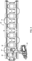
- FIGS. 4-6 illustrate a tool storage system 46 in accordance with another embodiment.
- Features of the tool storage system 46 may be applied in the tool storage system 10, and features of the tool storage system 10 may be applied in the tool storage system 46.
- a bracket 18' of the tool storage system 46 is secured to the tool 22 by the stud 38. Accordingly, the tool 22 is movable between a first engaged position in which the tool 22 engages the cleat 26 and a second engaged position in which the bracket 18' engages another support surface (e.g., another bracket, a belt clip, the other storage system 10, etc.) and a third position in which the tool 22 is removed from both the cleat 26 and the other support surface.
- another support surface e.g., another bracket, a belt clip, the other storage system 10, etc.
- the bracket 18' may be otherwise dimensioned such that one bracket 18' may engage a single cleat 26 of the rail 14. Further, the bracket 18' provides a quick release retention mechanism 30 which permits quick release of the tool 22 from the rail 14 by movement of the bracket 18' away from the adjacent cleats 26.
- the retainer 50 extends from the bracket 18' in a direction towards the rail 14 (i.e., into the page as viewed in FIG. 4 ).
- the retainer 50 of the bracket 18' is attachable to another support surface (e.g., a belt clip, a different tool storage component, a vehicle mounted storage system, etc.), which may be separate from the rail 14.
- the bracket 18' includes an engagement surface (provided by the periphery of the bracket 18') which is operable to attach the bracket 18' to the rail 14.
- the bracket 18' includes a retainer 50 which is operable to attach the bracket 18' to another support surface.
- the tool storage system 54 includes a bracket 18" which holds a bit bar (i.e., a bar, a bit storage member) 58.
- the bit bar 58 may be removably coupled to the bracket 18".
- the bit bar 58 may be pivotable relative to the bracket 18".
- the bit bar 58 includes recesses 62 which are dimensioned to removably receive bits (i.e., tool bits) 66 for use with the tool 22.
- the bracket 18" further includes a retainer 50 similar to the retainer 50 of the bracket 18'.
- the bracket 18" is provided with an engagement surface (provided by the periphery of the bracket 18") which is operable to attach the bracket 18" to the rail 14.
- the bracket 18" includes the retainer 50 which is operable to attach the bracket 18" to another support surface (e.g., another bracket, a belt clip, the other storage system 10, etc.), which may be separate from the rail 14.
- the periphery of the bracket 18" is configured (i.e., dimensioned and toleranced) to removably engage (i.e., nest between) adjacent cleats 26 of the rail 14, and the retainer 50 is configured (i.e., dimensioned and toleranced) to removably engage a belt clip.
- the bit bar 58 is configured (i.e., dimensioned and toleranced) to removably engage the bracket 18".
- the bits 66 are configured (i.e., dimensioned and toleranced) to removable engage the recesses 62.
- the bits 66 may be selectively coupled to the recesses 62, (and thus coupled to the bit bar 58 and the bracket 18") independently of whether the bracket 18" is secured to the cleat(s) 26 and the rail 14. Accordingly, a user can remove the tool 22 with the bracket 18" attached thereto, transport the tool 22 and the bracket 18" to a position away from the rail 14, and selectively remove the bit 66 or a plurality of bits 66 from their corresponding recesses 62 at the position away from the rail 14.
Landscapes
- Engineering & Computer Science (AREA)
- Mechanical Engineering (AREA)
- Battery Mounting, Suspending (AREA)
- Workshop Equipment, Work Benches, Supports, Or Storage Means (AREA)
- Casings For Electric Apparatus (AREA)
- Fittings On The Vehicle Exterior For Carrying Loads, And Devices For Holding Or Mounting Articles (AREA)
Abstract
Description
- This application claims priority to
U.S. Provisional Patent Application No. 63/171,915, filed April 7, 2021 - The present disclosure relates to storage systems, and more particularly to wall mounted storage systems for tools and the like.
- Hand tools, power tools, and associated accessories such as batteries, tool bits, fasteners, and the like, may be moved frequently between a storage space and a work space. One aspect of accessibility is a user's ability to quickly store an object and remove the object from storage. Another aspect of accessibility is the storage system's ability to engage many objects with a standardized connection mechanism between the system and the object. This may also permit an object to engage the storage system at a plurality of locations. Finally, accessible storage systems provide options for accessing tools and bits with tools either directly from the storage system, or from a mobile storage system (i.e., on a tool belt) that is movable with the user between the storage system and a position adjacent a work space.
- In one independent aspect, a storage system includes a support member having a cleat thereon, a bracket engageable with the cleat, and a lever movable between a locked position and an unlocked position. The storage system further includes an object permitted to be coupled or uncoupled relative to the bracket while the lever is in the unlocked position, the object being secured to the bracket while the lever is in the locked position.
- In another independent aspect, a storage system is configured to support a tool. The support system includes a first support member having a cleat thereon, and a bracket. The bracket is configured to engage the cleat. The bracket includes a retainer configured to engage a support surface of a second support member separate from the first support member. The bracket is selectively coupled to the tool. While the bracket is coupled to the tool, the bracket and the tool and movable between a first position, a second position, and a third position. While in the first position, the bracket engages the cleat and supports the tool relative to the cleat. While in the second position, the bracket engages the support surface and supports the tool relative to the support surface. While in the third position, the bracket is removed from the cleat and the support surface.
- In yet another independent aspect, a storage system is configured to support a tool. The storage system includes a support member having a cleat thereon and a bracket. The bracket is configured to engage the cleat. The bracket includes a bit storage member including a plurality of recesses each configured to selectively receive one of a plurality of tool bits therein. The bracket further includes a retainer configured to secure the bracket to the tool.
- Other aspects of the disclosure will become apparent by consideration of the detailed description and accompanying drawings.
-
-
FIG. 1 is a front view of a tool storage system including a support member, a bracket, and a tool. -
FIG. 2 is an exploded perspective view of the bracket and a portion of the tool ofFIG. 1 . -
FIG. 3 is a perspective view of a portion of the tool ofFIG. 1 . -
FIG. 4 is a front view of a tool storage system including a support member, a tool, and a bracket according to another embodiment. -
FIG. 5 is a perspective view of the support member, the tool, and the bracket ofFIG. 4 . -
FIG. 6 is another perspective view of the bracket and the tool ofFIG. 4 . -
FIG. 7 is a perspective view of a tool, a support member, and a bracket according to another embodiment. -
FIG. 8 is another perspective view of the tool, the support member, and the bracket ofFIG. 7 . -
FIG. 9 is another perspective view of the tool, the support member, and the bracket ofFIG. 7 . - Before any aspects are explained in detail, it is to be understood that the disclosure is not limited in its application to the details of construction and the arrangement of components set forth in the following description or illustrated in the following drawings. The disclosure is capable of other embodiments and of being practiced or of being carried out in various ways. Also, it is to be understood that the phraseology and terminology used herein is for the purpose of description and should not be regarded as limiting.
-
FIG. 1 illustrates atool storage system 10 including a support member (e.g., a panel or rail 14), abracket 18, and an object (e.g., a tool, optionally a power tool) 22. Therail 14 is mounted on a wall W (i.e., a support surface) by a support fastener 23 (FIG. 1 ). The illustratedrail 14 may include multiple projections orcleats 26 which project outwardly from the wall W (seeFIG. 5 ) and protrude from therail 14. In other embodiments, therail 14 may include asingle cleat 26. In the illustrated embodiment, thebracket 18 of thetool storage system 10 engages (i.e., is nested between)multiple cleats 26 and is supported betweenadjacent cleats 26. In other embodiments, thebracket 18 may engage thecleats 26 in a different manner, and/or may engage asingle cleat 26. Thebracket 18 is coupled to thetool 22 for connecting thetool 22 to therail 14. Therail 14 may support more than asingle bracket 18 andtool 22 in a similar manner as described with respect to the illustratedbracket 18 andtool 22. -
FIG. 2 illustrates a retention mechanism 30 configured to connect thetool 22 to thebracket 18. In the illustrated embodiment, the retention mechanism 30 includes alever 34 that is supported for movement with respect to thebracket 18. In the illustrated embodiment, thelever 34 is positioned at least partially within a lever receptacle 18a on thebracket 18, and is movable between a locked position (illustrated in solid lines) and an unlocked or released position (illustrated in dashed lines). In some embodiments, thelever 34 may be biased toward the locked position by a biasing force and is movable to the unlocked position in response to a force exerted against the biasing force. In the illustrated embodiment, the retention mechanism 30 provides a quick release retention mechanism 30 in which an operator can quickly secure and/or remove thetool 22 from thebracket 18. - With reference to
FIG. 2 , thelever 34 is movable between a locked position (illustrated as the lever 34) in which thetool 22 is secured to thebracket 18 and thus therail 14 and the unlocked position (illustrated as the lever 34') in which thetool 22 is separable from thebracket 18. In the locked position, thetool 22 is coupled to thebracket 18 by thelever 34. The lever 34' is translatable between the locked position (illustrated as the lever 34) and the unlocked position (illustrated as the lever 34'). More specifically, as viewed inFIG. 1 , thelever 34 is translated in a direction that is perpendicular (i.e., transverse) to the direction in which thecleats 26 project from therail 14. In the illustrated embodiment, at least a portion of thelever 34 is received in the lever receptacle 18a in both the locked position (lever 34) and the unlocked position (lever 34'). - As illustrated in
FIGS. 2 and3 , the retention mechanism 30 further includes astud 38 which is secured to thetool 22. In the illustrated embodiment, thestud 38 is located adjacent abattery receptacle 42 of thetool 22. Further, in the illustrated embodiment, thestud 38 projects laterally away from thebattery receptacle 42 of thetool 22. Thestud 38 is movable to engage thelever 34 and to provide the force exerted against the biasing force to retract thelever 34 to the unlocked position (illustrated as the lever 34'). Subsequently, thestud 38 is configured to engage thelever 34 to connect thetool 22 thelever 34. Thebracket 18 includes an opening 18b. The opening 18b is in communication with the lever receptacle 18a. In the illustrated embodiment, the lever receptacle 18a and the opening 18b are spaces within thebracket 18 and are interconnected. In the locked position, thestud 38 is received within the opening 18b, and thelever 34 is in the locked position (indicated by the lever 34). At least a portion of thetool 22 is movable through the opening 18b and into the lever receptacle 18a within thebracket 18. In the illustrated embodiment, thestud 38 is removably coupled to thetool 22, and thestud 38 functions as an extension of thetool 22 which projects laterally away from thebattery receptacle 42. More specifically, thestud 38 functions as an extension of the portion of thetool 22 adjacent thebattery receptacle 42. In other embodiments, thetool 22 may directly engage the bracket 18 (e.g., may be received directly within the bracket 18). In this locked position, thestud 38 is supported by thebracket 18. Thelever 34 thus inhibits removal of thestud 38 from the opening 18b. - In transitioning to the unlocked position, a user may conduct a "quick release" of the
lever 34 to the unlocked position (illustrated as the lever 34'). Thestud 38 and thus thetool 22 can then be removed from thebracket 18. Accordingly, thestud 38 can be quickly engaged and disengaged from thebracket 18. Additionally or alternatively, thestud 38 may be used to provide a transition force and to connect thetool 22 to another support surface (e.g., anotherbracket 18, a belt clip, another storage system 10). Thelever 34 may be biased by a spring 44 (shown schematically inFIG. 2 ) toward the locked position in which thelever 34 secures thestud 38 to thebracket 18. In other embodiments, thelever 34 may be biased and/or held in the locked position or the unlocked position by other means (e.g., a ratcheting mechanism). - To couple the
tool 22 to therail 14, thebracket 18 may be first secured to therail 14 as illustrated inFIG. 1 . As illustrated inFIG. 2 , thetool 22 may then be moved to cause thestud 38 to engage thelever 34 of thebracket 18. In the illustrated embodiment, insertion of thestud 38 into a void of thelever 34 causes movement of thelever 34 from the locked position to the unlocked position. Once thestud 38 passes a threshold position through thelever 34, thelever 34 is retracted (by the biasing force of the spring 44) from the unlocked position to the locked position in which thelever 34 secures thetool 22 to thebracket 18, and thus, therail 14. - To release or uncouple the
tool 22 from therail 14, thetool 22 may be moved in a direction away from the wall W, causing thestud 38 to press on thelever 34 and move thelever 34 from the locked position to the unlocked position. Once thestud 38 passes a threshold position, thelever 34 is returned to the locked position (by the biasing force of the spring 44) and thestud 38 and thetool 22 is removed from thebracket 18. The connecting and releasing operations permit quick coupling and uncoupling of thetool 22 with respect to therail 14. Further, given the standardized sizes of thecleats 26 andbrackets 18, thetool 22 may be quickly moved to engage anotherbracket 18 in a different location (e.g., adjacent a desired work space). -
FIGS. 4-6 illustrate atool storage system 46 in accordance with another embodiment. Features of thetool storage system 46 may be applied in thetool storage system 10, and features of thetool storage system 10 may be applied in thetool storage system 46. As best illustrated inFIG. 6 , a bracket 18' of thetool storage system 46 is secured to thetool 22 by thestud 38. Accordingly, thetool 22 is movable between a first engaged position in which thetool 22 engages thecleat 26 and a second engaged position in which the bracket 18' engages another support surface (e.g., another bracket, a belt clip, theother storage system 10, etc.) and a third position in which thetool 22 is removed from both thecleat 26 and the other support surface. In the illustrated embodiment, the bracket 18' is located adjacent thebattery receptacle 42 of the tool with thestud 38 projecting laterally away from thebattery receptacle 42 of thetool 22. The bracket 18' is dimensioned to be supported betweenadjacent cleats 26 of therail 14. The bracket 18' may be removed from one set of adjacent cleats 26 (i.e., afirst cleat 26 and a second cleat 26) and engaged to another set of adjacent cleats 26 (i.e., the two adjacent cleats at another position on the rail). The bracket 18' may be dimensioned such that one bracket 18' may be nested betweenadjacent cleats 26 of therail 14. The bracket 18' may be otherwise dimensioned such that one bracket 18' may engage asingle cleat 26 of therail 14. Further, the bracket 18' provides a quick release retention mechanism 30 which permits quick release of thetool 22 from therail 14 by movement of the bracket 18' away from theadjacent cleats 26. - As best illustrated in
FIG. 6 , the bracket 18' further includes aretainer 50. In the illustrated embodiment, theretainer 50 is formed as a cantilevered hook. The periphery of the bracket 18' includes a wing tip 18c formed at a distal end of the bracket 18'. The wing tip 18c provides an engagement surface of the bracket 18' which is engageable and removable fromadjacent cleats 26 of therail 14. The wing tip 18c extends laterally away from a body portion 18d of the bracket 18'. Other engagement surfaces are possible. Theretainer 50 extends from the body portion 18d. When the bracket 18' is in the first position (engaged with thecleat 26 as inFIG. 4 ), the retainer 50 (i.e., the cantilevered hook) extends from the bracket 18' in a direction towards the rail 14 (i.e., into the page as viewed inFIG. 4 ). Once the bracket 18' is removed from therail 14, theretainer 50 of the bracket 18' is attachable to another support surface (e.g., a belt clip, a different tool storage component, a vehicle mounted storage system, etc.), which may be separate from therail 14. The bracket 18' includes an engagement surface (provided by the periphery of the bracket 18') which is operable to attach the bracket 18' to therail 14. Further, the bracket 18' includes aretainer 50 which is operable to attach the bracket 18' to another support surface. In the illustrated embodiment, the periphery of the bracket 18' is configured (i.e., dimensioned and toleranced) to removably engage (i.e., nest between)adjacent cleats 26 of therail 14, and theretainer 50 is configured (i.e., dimensioned and toleranced) to removably engage a belt clip. With thetool storage system 46, a user is capable of removing the bracket 18' and thetool 22 from therail 14, attaching thetool 22 to the user's belt, and moving from therail 14 to a work space while having access to but not directly holding thetool 22. -
FIGS. 7-9 illustrate atool storage system 54 in accordance with another embodiment. Features of thetool storage system 54 may be applied in thetool storage system 10 and/or thetool storage system 46, and features of thetool storage systems tool storage system 54. - As best illustrated in
FIG. 7 , thetool storage system 54 includes abracket 18" which holds a bit bar (i.e., a bar, a bit storage member) 58. The bit bar 58 may be removably coupled to thebracket 18". The bit bar 58 may be pivotable relative to thebracket 18". The bit bar 58 includesrecesses 62 which are dimensioned to removably receive bits (i.e., tool bits) 66 for use with thetool 22. As best illustrated inFIGS. 8 and9 , thebracket 18" further includes aretainer 50 similar to theretainer 50 of the bracket 18'. Thebracket 18" is provided with an engagement surface (provided by the periphery of thebracket 18") which is operable to attach thebracket 18" to therail 14. Further, thebracket 18" includes theretainer 50 which is operable to attach thebracket 18" to another support surface (e.g., another bracket, a belt clip, theother storage system 10, etc.), which may be separate from therail 14. In the illustrated embodiment, the periphery of thebracket 18" is configured (i.e., dimensioned and toleranced) to removably engage (i.e., nest between)adjacent cleats 26 of therail 14, and theretainer 50 is configured (i.e., dimensioned and toleranced) to removably engage a belt clip. The bit bar 58 is configured (i.e., dimensioned and toleranced) to removably engage thebracket 18". Thebits 66 are configured (i.e., dimensioned and toleranced) to removable engage therecesses 62. Thebits 66 may be selectively coupled to therecesses 62, (and thus coupled to thebit bar 58 and thebracket 18") independently of whether thebracket 18" is secured to the cleat(s) 26 and therail 14. Accordingly, a user can remove thetool 22 with thebracket 18" attached thereto, transport thetool 22 and thebracket 18" to a position away from therail 14, and selectively remove thebit 66 or a plurality ofbits 66 from their correspondingrecesses 62 at the position away from therail 14. - Although aspects of the disclosure have been described in detail with reference to certain preferred embodiments, variations and modifications exist within the scope and spirit of one or more independent aspects as described. One or more independent features and/or advantages may be set forth in the following claims.
- The preferred aspects of the present disclosure may be summarised as follows::
- 1. A storage system comprising:
- a support member having a cleat thereon;
- a bracket engageable with the cleat;
- a lever movable between a locked position and an unlocked position; and
- an object being permitted to be coupled or uncoupled relative to the bracket while the lever is in the unlocked position, the object being secured to the bracket while the lever is in the locked position.
- 2. The storage system of aspect 1, further comprising a spring biasing the lever toward the locked position.
- 3. The storage system of aspect 1, wherein the support member has a plurality of cleats, and the bracket is configured to engage at least two cleats of the plurality of cleats.
- 4. The storage system of aspect 1, wherein the bracket includes an opening in communication with a lever receptacle, the lever receptacle, and at least a portion of the object is movable through the opening and into the lever receptacle.
- 5. The storage system of aspect 4, wherein the object is a power tool including a battery receptacle, and the portion of the object is a stud that is removably coupled to the object and projects laterally away from the battery receptacle.
- 6. The storage system of aspect 1, wherein the lever is translatable between the locked position and the unlocked position, the lever translated in a direction transverse to the extension of the cleat from the support member.
- 7. A storage system configured to support a tool, the storage system comprising:
- a first support member having a cleat thereon;
- a bracket configured to engage the cleat, the bracket including a retainer configured to engage a support surface of a second support member separate from the first support member, the bracket selectively coupled to the tool, while the bracket is coupled to the tool, the bracket and the tool are movable between a first position, a second position, and a third position,
- while in the first position, the bracket engages the cleat and supports the tool relative to the cleat,
- while in the second position, the bracket engages the support surface and supports the tool relative to the support surface, and
- while in the third position the bracket is removed from the cleat and the support surface.
- 8. The storage system of aspect 7, wherein the first support member further includes a second cleat thereon, wherein in the first position, the bracket is configured to engage the cleat and the second cleat.
- 9. The storage system of aspect 8, wherein the support member further includes a third cleat thereon, wherein in a fourth position, the bracket is configured to engage the cleat and the third cleat.
- 10. The storage system of aspect 7, wherein the bracket includes a body portion and a wing extending laterally away from the body portion, the wing engageable with the cleat while the bracket and the tool are in the first position.
- 11. The storage system of
aspect 10, wherein the bracket further includes a wing tip positioned at a distal end of the wing spaced from the body portion, the wing tip engageable with the cleat while the bracket and the tool are in the first position. - 12. The storage system of aspect 7, wherein the bracket includes a body portion and a retainer, the retainer being formed as a cantilevered hook extending from the body portion.
- 13. The storage system of aspect 12, wherein while the bracket is coupled to the tool and positioned in the first position, the cantilevered hook extends from the bracket in a direction towards the first support member.
- 14. The storage system of aspect 7, further comprising a stud coupling the object to the bracket.
- 15. The storage system of
aspect 14, wherein the object is a power tool including a battery receptacle and the stud projects laterally away from the battery receptacle. - 16. A storage system configured to support a tool, the storage system comprising:
- a support member having a cleat thereon;
- a bracket configured to engage the cleat, the bracket including
- bit storage member including a plurality of recesses, each of the recesses configured to selectively receive one of a plurality of tool bits therein, and
- a retainer configured to secure the bracket to the tool.
- 17. The storage system of aspect 16, wherein the retainer is configured to engage a support surface of a second support member separate from the support member.
- 18. The storage system of aspect 16, wherein selective receipt of each tool bit with the bit storage member is independent of whether the bracket is engaged with the cleat.
- 19. The storage system of aspect 16, wherein while the bracket is secured to the tool by the retainer, the bracket and the tool are movable between a first position in which the bracket engages cleat and the bracket supports the tool relative to the cleat, a second position in which the bracket engages a support surface of a second support member separate from the support member and supports the tool relative to the support surface, and a third position in which the bracket is removed from the cleat and the support surface.
- 20. The storage system of aspect 16, wherein the bit storage member is removably coupled to the bracket.
Claims (9)
- A storage system configured to support a tool, the storage system comprising:a first support member having a cleat thereon;a bracket configured to engage the cleat, the bracket including a retainer configured to engage a support surface of a second support member separate from the first support member, the bracket selectively coupled to the tool, while the bracket is coupled to the tool, the bracket and the tool are movable between a first position, a second position, and a third position,while in the first position, the bracket engages the cleat and supports the tool relative to the cleat,while in the second position, the bracket engages the support surface and supports the tool relative to the support surface, andwhile in the third position the bracket is removed from the cleat and the support surface.
- The storage system of claim 1, wherein the first support member further includes a second cleat thereon, wherein in the first position, the bracket is configured to engage the cleat and the second cleat.
- The storage system of claim 2, wherein the support member further includes a third cleat thereon, wherein in a fourth position, the bracket is configured to engage the cleat and the third cleat.
- The storage system of claim 1, wherein the bracket includes a body portion and a wing extending laterally away from the body portion, the wing engageable with the cleat while the bracket and the tool are in the first position.
- The storage system of claim 4, wherein the bracket further includes a wing tip positioned at a distal end of the wing spaced from the body portion, the wing tip engageable with the cleat while the bracket and the tool are in the first position.
- The storage system of claim 1, wherein the bracket includes a body portion and a retainer, the retainer being formed as a cantilevered hook extending from the body portion.
- The storage system of claim 6, wherein while the bracket is coupled to the tool and positioned in the first position, the cantilevered hook extends from the bracket in a direction towards the first support member.
- The storage system of claim 1, further comprising a stud coupling the object to the bracket.
- The storage system of claim 8, wherein the object is a power tool including a battery receptacle and the stud projects laterally away from the battery receptacle.
Applications Claiming Priority (2)
| Application Number | Priority Date | Filing Date | Title |
|---|---|---|---|
| US202163171915P | 2021-04-07 | 2021-04-07 | |
| EP22166420.4A EP4137276B1 (en) | 2021-04-07 | 2022-04-03 | Tool storage system |
Related Parent Applications (2)
| Application Number | Title | Priority Date | Filing Date |
|---|---|---|---|
| EP22166420.4A Division-Into EP4137276B1 (en) | 2021-04-07 | 2022-04-03 | Tool storage system |
| EP22166420.4A Division EP4137276B1 (en) | 2021-04-07 | 2022-04-03 | Tool storage system |
Publications (2)
| Publication Number | Publication Date |
|---|---|
| EP4578601A2 true EP4578601A2 (en) | 2025-07-02 |
| EP4578601A3 EP4578601A3 (en) | 2025-09-10 |
Family
ID=81326995
Family Applications (2)
| Application Number | Title | Priority Date | Filing Date |
|---|---|---|---|
| EP25176702.6A Pending EP4578601A3 (en) | 2021-04-07 | 2022-04-03 | Tool storage system |
| EP22166420.4A Active EP4137276B1 (en) | 2021-04-07 | 2022-04-03 | Tool storage system |
Family Applications After (1)
| Application Number | Title | Priority Date | Filing Date |
|---|---|---|---|
| EP22166420.4A Active EP4137276B1 (en) | 2021-04-07 | 2022-04-03 | Tool storage system |
Country Status (5)
| Country | Link |
|---|---|
| US (1) | US20220324093A1 (en) |
| EP (2) | EP4578601A3 (en) |
| CN (1) | CN218137944U (en) |
| AU (1) | AU2022202334A1 (en) |
| CA (1) | CA3153983A1 (en) |
Families Citing this family (6)
| Publication number | Priority date | Publication date | Assignee | Title |
|---|---|---|---|---|
| CA3220384A1 (en) * | 2021-07-08 | 2023-01-12 | Yaron Brunner | Container mounting and locomoting system |
| US12179335B2 (en) * | 2022-07-12 | 2024-12-31 | Techtronic Cordless Gp | Storage system and container for same |
| US11926034B1 (en) * | 2022-10-18 | 2024-03-12 | Jianyong Yu | Tool hanger |
| USD1095035S1 (en) * | 2023-03-21 | 2025-09-30 | Milwaukee Electric Tool Corporation | Accessory storage device |
| USD1078431S1 (en) * | 2023-06-21 | 2025-06-10 | Jianyong Yu | Tool hanger panel |
| EP4667165A1 (en) * | 2024-06-20 | 2025-12-24 | Black & Decker, Inc. | A hanger accessory and hanger system |
Family Cites Families (47)
| Publication number | Priority date | Publication date | Assignee | Title |
|---|---|---|---|---|
| US4722113A (en) * | 1985-12-02 | 1988-02-02 | Olsson Arvid T | Mop handle stabilizer |
| US4763797A (en) * | 1987-08-14 | 1988-08-16 | Egan George E | Ski rack |
| US5035389A (en) * | 1990-08-20 | 1991-07-30 | Wang Shu San | Mounting device |
| US5472167A (en) * | 1994-01-26 | 1995-12-05 | Med-Safe Systems, Inc. | Secure mounting bracket for disposable sharps container |
| US5810232A (en) * | 1996-07-10 | 1998-09-22 | Meurer; John | Tool support |
| US5897002A (en) * | 1996-09-18 | 1999-04-27 | Carlino; Sam | Tool hanging rack |
| DE19718833C1 (en) * | 1997-05-05 | 1998-09-24 | Konstanze Saathoff Fa | Manually operated, power-driven tool, such as pneumatic screw driver |
| US5957421A (en) * | 1998-01-14 | 1999-09-28 | Barbour; Lee | Retainer device |
| US5931299A (en) * | 1999-01-14 | 1999-08-03 | Hsieh; Chih-Ching | Toolholder |
| US7228977B2 (en) * | 2003-06-16 | 2007-06-12 | Whirlpool Corporation | Workroom storage system |
| US20050102793A1 (en) * | 2003-11-19 | 2005-05-19 | Leo Shih | Hand tool holder |
| US20050247653A1 (en) * | 2004-05-06 | 2005-11-10 | Dr. Brooks Innovations, L.L.C. | System for holding implements |
| US20060037920A1 (en) * | 2004-08-23 | 2006-02-23 | Laszlo Baranya | Holder for elongated articles |
| US7424958B1 (en) * | 2005-02-16 | 2008-09-16 | Eley John H | Storage and organization system for articles |
| US20080054142A1 (en) * | 2006-04-21 | 2008-03-06 | Deland Martin L | Display system |
| US20080000853A1 (en) * | 2006-06-13 | 2008-01-03 | Jung Li Huang | Holder for implements |
| DE102007050712A1 (en) * | 2007-10-22 | 2009-04-23 | Zyrus Beteiligungsgesellschaft Mbh & Co. Patente I Kg | Tool receiving system with pull-out and return device, in particular with a coil |
| US20090145866A1 (en) * | 2007-12-10 | 2009-06-11 | Michael Harmik Panosian | Wall organizing system |
| US8096520B2 (en) * | 2008-06-04 | 2012-01-17 | Sohn Cheryl L | Connector system |
| US7950534B2 (en) * | 2009-05-27 | 2011-05-31 | Jui-Chien Kao | Hand tool rack |
| US8915382B2 (en) * | 2009-09-15 | 2014-12-23 | Peter Totman | Apparatus and system for supporting a ski |
| US8640890B2 (en) * | 2010-07-06 | 2014-02-04 | Andrew J. Schiller | Bag rack system |
| US20120091086A1 (en) * | 2010-10-18 | 2012-04-19 | Rubbermaid Incorporated | Rail storage system |
| US8678206B2 (en) * | 2011-01-28 | 2014-03-25 | Thomas Kubiniec | System for storage and transport of weapons |
| US20130047386A1 (en) * | 2011-02-17 | 2013-02-28 | Magpul Industries Corp. | Modular Stowage System |
| US8814108B2 (en) * | 2012-08-28 | 2014-08-26 | David Bernstein | Product display system |
| US20140097217A1 (en) * | 2012-09-06 | 2014-04-10 | Sean Michael Walsh | Tool Holding Device |
| US20160286985A1 (en) * | 2013-03-01 | 2016-10-06 | Akro-Mils | Inclined panel for industrial bins and inclined rack systems |
| US9205552B2 (en) * | 2014-01-20 | 2015-12-08 | Jui-Chien Kao | Magnetic hanging frame for hand tools |
| US9193063B2 (en) * | 2014-03-10 | 2015-11-24 | Kevin Huang | Tool positioning pad |
| TWM513768U (en) * | 2015-07-16 | 2015-12-11 | shu-hui Ye | Tool storage device |
| US9962827B2 (en) * | 2016-03-24 | 2018-05-08 | Jui-Chien Kao | Hand tool frame |
| US10441077B2 (en) * | 2016-12-14 | 2019-10-15 | Sizable Enterprises Incorporated | Compartment divider assembly |
| US11103989B2 (en) * | 2017-06-14 | 2021-08-31 | Jonathan Hurley | Interchangeable and interconnectable tool organizing device |
| US10500713B2 (en) * | 2017-09-14 | 2019-12-10 | Black & Decker Inc. | Wall hanging system |
| US10932593B2 (en) * | 2018-08-30 | 2021-03-02 | Edsal Manufacturing Company, Inc. | Organizer set with retention system and method of making same |
| EP4029657A1 (en) * | 2020-08-07 | 2022-07-20 | Techtronic Cordless GP | Modular storage system |
| US11884456B2 (en) * | 2020-09-25 | 2024-01-30 | Techtronic Cordless Gp | Tool storage system |
| US12648642B2 (en) * | 2020-10-20 | 2026-06-09 | Techtronic Cordless Gp | Storage system |
| EP4232243A4 (en) * | 2020-10-26 | 2024-12-11 | Milwaukee Electric Tool Corporation | COUPLING MECHANISM FOR A UTILITY MODULE |
| EP4183528A1 (en) * | 2021-07-12 | 2023-05-24 | Techtronic Cordless GP | Storage system |
| US12115649B2 (en) * | 2021-07-30 | 2024-10-15 | Milwaukee Electric Tool Corporation | Modular tool storage system with shop storage device |
| US11826896B2 (en) * | 2021-12-14 | 2023-11-28 | Matthias Keller | Power tool and battery support racks and methods of manufacturing |
| US20230102378A1 (en) * | 2021-09-30 | 2023-03-30 | Klein Tools, Inc. | Accessory mount system for use with elevated work platforms |
| CA3179150A1 (en) * | 2021-10-18 | 2023-04-18 | Techtronic Cordless Gp | Modular accessories and storage systems |
| USD1088790S1 (en) * | 2021-10-18 | 2025-08-19 | Midwest Innovative Products, Llc | Tool holder |
| CN222570740U (en) * | 2021-11-24 | 2025-03-07 | 米沃奇电动工具公司 | Pliers storage rack and a storage rack for storing pliers with handles biased toward an open position |
-
2022
- 2022-04-03 EP EP25176702.6A patent/EP4578601A3/en active Pending
- 2022-04-03 EP EP22166420.4A patent/EP4137276B1/en active Active
- 2022-04-04 CA CA3153983A patent/CA3153983A1/en active Pending
- 2022-04-05 US US17/713,921 patent/US20220324093A1/en not_active Abandoned
- 2022-04-06 CN CN202220781499.4U patent/CN218137944U/en active Active
- 2022-04-07 AU AU2022202334A patent/AU2022202334A1/en active Pending
Also Published As
| Publication number | Publication date |
|---|---|
| EP4137276B1 (en) | 2025-09-17 |
| AU2022202334A1 (en) | 2022-10-27 |
| EP4137276C0 (en) | 2025-09-17 |
| EP4137276A3 (en) | 2023-05-17 |
| EP4578601A3 (en) | 2025-09-10 |
| CN218137944U (en) | 2022-12-27 |
| EP4137276A2 (en) | 2023-02-22 |
| US20220324093A1 (en) | 2022-10-13 |
| CA3153983A1 (en) | 2022-10-07 |
Similar Documents
| Publication | Publication Date | Title |
|---|---|---|
| EP4137276A2 (en) | Tool storage system | |
| US11964632B2 (en) | Vehicle accessory attachment system and attachment method | |
| US6131781A (en) | Equipment load assist to roof rack | |
| US20080296449A1 (en) | Quick release electronics platform | |
| US6948732B2 (en) | Convertible cargo rack | |
| US7878743B2 (en) | Vehicle article carrier having cooperative tie-down and load bar assemblies | |
| US6920810B1 (en) | Method and apparatus for attaching and detaching an attachable device | |
| US4502365A (en) | Socket wrench extension | |
| EP1344609A1 (en) | Tool and accessory carrying system | |
| US10144335B2 (en) | Spring loaded tie down assembly and method for use with a vehicle cargo area | |
| US20070210021A1 (en) | Tool holder with a locking mechanism | |
| TW201217121A (en) | capable of receiving a complete set of larger tools or providing larger storing space | |
| EP1940266A2 (en) | A tool box fastening device for fastening a tool box set to a vertical wall | |
| US20020084622A1 (en) | Spotting receiver hitch | |
| US11465192B2 (en) | Tool cartridge | |
| US7124864B2 (en) | Quick release socket connector | |
| US6539831B2 (en) | Circular power saw | |
| US11130393B2 (en) | Vehicle cargo cover system and related componentry | |
| US4485549A (en) | Apparatus for changing the tools of a punch press | |
| US6457734B1 (en) | Multipurpose front mounted hitch receiver | |
| US8152120B2 (en) | Multipurpose support for attachments mountable to the tow hitch of a vehicle | |
| JP4663217B2 (en) | Tape measure holder | |
| US20250091527A1 (en) | Cargo box tool holder clamp | |
| JPH0120767Y2 (en) | ||
| US20240401622A1 (en) | Directional drill quick attach device and method |
Legal Events
| Date | Code | Title | Description |
|---|---|---|---|
| PUAI | Public reference made under article 153(3) epc to a published international application that has entered the european phase |
Free format text: ORIGINAL CODE: 0009012 |
|
| STAA | Information on the status of an ep patent application or granted ep patent |
Free format text: STATUS: THE APPLICATION HAS BEEN PUBLISHED |
|
| AC | Divisional application: reference to earlier application |
Ref document number: 4137276 Country of ref document: EP Kind code of ref document: P |
|
| AK | Designated contracting states |
Kind code of ref document: A2 Designated state(s): AL AT BE BG CH CY CZ DE DK EE ES FI FR GB GR HR HU IE IS IT LI LT LU LV MC MK MT NL NO PL PT RO RS SE SI SK SM TR |
|
| PUAL | Search report despatched |
Free format text: ORIGINAL CODE: 0009013 |
|
| AK | Designated contracting states |
Kind code of ref document: A3 Designated state(s): AL AT BE BG CH CY CZ DE DK EE ES FI FR GB GR HR HU IE IS IT LI LT LU LV MC MK MT NL NO PL PT RO RS SE SI SK SM TR |
|
| RIC1 | Information provided on ipc code assigned before grant |
Ipc: B25H 3/00 20060101AFI20250805BHEP Ipc: B25H 3/04 20060101ALI20250805BHEP |
|
| STAA | Information on the status of an ep patent application or granted ep patent |
Free format text: STATUS: REQUEST FOR EXAMINATION WAS MADE |
|
| 17P | Request for examination filed |
Effective date: 20260309 |
|
| GRAP | Despatch of communication of intention to grant a patent |
Free format text: ORIGINAL CODE: EPIDOSNIGR1 |
|
| STAA | Information on the status of an ep patent application or granted ep patent |
Free format text: STATUS: GRANT OF PATENT IS INTENDED |
|
| INTG | Intention to grant announced |
Effective date: 20260701 |