EP4578563A1 - Spraying system diagnostics and methods thereof - Google Patents
Spraying system diagnostics and methods thereof Download PDFInfo
- Publication number
- EP4578563A1 EP4578563A1 EP23220446.1A EP23220446A EP4578563A1 EP 4578563 A1 EP4578563 A1 EP 4578563A1 EP 23220446 A EP23220446 A EP 23220446A EP 4578563 A1 EP4578563 A1 EP 4578563A1
- Authority
- EP
- European Patent Office
- Prior art keywords
- pressure
- sprinkling
- sprinkling device
- sensor
- repetitive
- Prior art date
- Legal status (The legal status is an assumption and is not a legal conclusion. Google has not performed a legal analysis and makes no representation as to the accuracy of the status listed.)
- Pending
Links
Images


Classifications
-
- B—PERFORMING OPERATIONS; TRANSPORTING
- B05—SPRAYING OR ATOMISING IN GENERAL; APPLYING FLUENT MATERIALS TO SURFACES, IN GENERAL
- B05B—SPRAYING APPARATUS; ATOMISING APPARATUS; NOZZLES
- B05B1/00—Nozzles, spray heads or other outlets, with or without auxiliary devices such as valves, heating means
- B05B1/02—Nozzles, spray heads or other outlets, with or without auxiliary devices such as valves, heating means designed to produce a jet, spray, or other discharge of particular shape or nature, e.g. in single drops, or having an outlet of particular shape
- B05B1/08—Nozzles, spray heads or other outlets, with or without auxiliary devices such as valves, heating means designed to produce a jet, spray, or other discharge of particular shape or nature, e.g. in single drops, or having an outlet of particular shape of pulsating nature, e.g. delivering liquid in successive separate quantities
- B05B1/083—Nozzles, spray heads or other outlets, with or without auxiliary devices such as valves, heating means designed to produce a jet, spray, or other discharge of particular shape or nature, e.g. in single drops, or having an outlet of particular shape of pulsating nature, e.g. delivering liquid in successive separate quantities the pulsating mechanism comprising movable parts
-
- B—PERFORMING OPERATIONS; TRANSPORTING
- B05—SPRAYING OR ATOMISING IN GENERAL; APPLYING FLUENT MATERIALS TO SURFACES, IN GENERAL
- B05B—SPRAYING APPARATUS; ATOMISING APPARATUS; NOZZLES
- B05B12/00—Arrangements for controlling delivery; Arrangements for controlling the spray area
- B05B12/004—Arrangements for controlling delivery; Arrangements for controlling the spray area comprising sensors for monitoring the delivery, e.g. by displaying the sensed value or generating an alarm
-
- B—PERFORMING OPERATIONS; TRANSPORTING
- B05—SPRAYING OR ATOMISING IN GENERAL; APPLYING FLUENT MATERIALS TO SURFACES, IN GENERAL
- B05B—SPRAYING APPARATUS; ATOMISING APPARATUS; NOZZLES
- B05B12/00—Arrangements for controlling delivery; Arrangements for controlling the spray area
- B05B12/08—Arrangements for controlling delivery; Arrangements for controlling the spray area responsive to condition of liquid or other fluent material to be discharged, of ambient medium or of target ; responsive to condition of spray devices or of supply means, e.g. pipes, pumps or their drive means
- B05B12/085—Arrangements for controlling delivery; Arrangements for controlling the spray area responsive to condition of liquid or other fluent material to be discharged, of ambient medium or of target ; responsive to condition of spray devices or of supply means, e.g. pipes, pumps or their drive means responsive to flow or pressure of liquid or other fluent material to be discharged
-
- B—PERFORMING OPERATIONS; TRANSPORTING
- B05—SPRAYING OR ATOMISING IN GENERAL; APPLYING FLUENT MATERIALS TO SURFACES, IN GENERAL
- B05B—SPRAYING APPARATUS; ATOMISING APPARATUS; NOZZLES
- B05B15/00—Details of spraying plant or spraying apparatus not otherwise provided for; Accessories
- B05B15/14—Arrangements for preventing or controlling structural damage to spraying apparatus or its outlets, e.g. for breaking at desired places; Arrangements for handling or replacing damaged parts
-
- B—PERFORMING OPERATIONS; TRANSPORTING
- B08—CLEANING
- B08B—CLEANING IN GENERAL; PREVENTION OF FOULING IN GENERAL
- B08B9/00—Cleaning hollow articles by methods or apparatus specially adapted thereto
- B08B9/08—Cleaning containers, e.g. tanks
- B08B9/20—Cleaning containers, e.g. tanks by using apparatus into or on to which containers, e.g. bottles, jars, cans are brought
- B08B9/28—Cleaning containers, e.g. tanks by using apparatus into or on to which containers, e.g. bottles, jars, cans are brought the apparatus cleaning by splash, spray, or jet application, with or without soaking
-
- B—PERFORMING OPERATIONS; TRANSPORTING
- B08—CLEANING
- B08B—CLEANING IN GENERAL; PREVENTION OF FOULING IN GENERAL
- B08B9/00—Cleaning hollow articles by methods or apparatus specially adapted thereto
- B08B9/08—Cleaning containers, e.g. tanks
- B08B9/20—Cleaning containers, e.g. tanks by using apparatus into or on to which containers, e.g. bottles, jars, cans are brought
- B08B9/28—Cleaning containers, e.g. tanks by using apparatus into or on to which containers, e.g. bottles, jars, cans are brought the apparatus cleaning by splash, spray, or jet application, with or without soaking
- B08B9/30—Cleaning containers, e.g. tanks by using apparatus into or on to which containers, e.g. bottles, jars, cans are brought the apparatus cleaning by splash, spray, or jet application, with or without soaking and having conveyors
-
- B—PERFORMING OPERATIONS; TRANSPORTING
- B08—CLEANING
- B08B—CLEANING IN GENERAL; PREVENTION OF FOULING IN GENERAL
- B08B9/00—Cleaning hollow articles by methods or apparatus specially adapted thereto
- B08B9/08—Cleaning containers, e.g. tanks
- B08B9/20—Cleaning containers, e.g. tanks by using apparatus into or on to which containers, e.g. bottles, jars, cans are brought
- B08B9/28—Cleaning containers, e.g. tanks by using apparatus into or on to which containers, e.g. bottles, jars, cans are brought the apparatus cleaning by splash, spray, or jet application, with or without soaking
- B08B9/34—Arrangements of conduits or nozzles
-
- B—PERFORMING OPERATIONS; TRANSPORTING
- B05—SPRAYING OR ATOMISING IN GENERAL; APPLYING FLUENT MATERIALS TO SURFACES, IN GENERAL
- B05B—SPRAYING APPARATUS; ATOMISING APPARATUS; NOZZLES
- B05B1/00—Nozzles, spray heads or other outlets, with or without auxiliary devices such as valves, heating means
- B05B1/14—Nozzles, spray heads or other outlets, with or without auxiliary devices such as valves, heating means with multiple outlet openings; with strainers in or outside the outlet opening
- B05B1/16—Nozzles, spray heads or other outlets, with or without auxiliary devices such as valves, heating means with multiple outlet openings; with strainers in or outside the outlet opening having selectively- effective outlets
- B05B1/1627—Nozzles, spray heads or other outlets, with or without auxiliary devices such as valves, heating means with multiple outlet openings; with strainers in or outside the outlet opening having selectively- effective outlets with a selecting mechanism comprising a gate valve, a sliding valve or a cock
- B05B1/1672—Nozzles, spray heads or other outlets, with or without auxiliary devices such as valves, heating means with multiple outlet openings; with strainers in or outside the outlet opening having selectively- effective outlets with a selecting mechanism comprising a gate valve, a sliding valve or a cock the selectively-effective outlets being arranged on a tube or pipe
-
- B—PERFORMING OPERATIONS; TRANSPORTING
- B05—SPRAYING OR ATOMISING IN GENERAL; APPLYING FLUENT MATERIALS TO SURFACES, IN GENERAL
- B05B—SPRAYING APPARATUS; ATOMISING APPARATUS; NOZZLES
- B05B1/00—Nozzles, spray heads or other outlets, with or without auxiliary devices such as valves, heating means
- B05B1/30—Nozzles, spray heads or other outlets, with or without auxiliary devices such as valves, heating means designed to control volume of flow, e.g. with adjustable passages
- B05B1/32—Nozzles, spray heads or other outlets, with or without auxiliary devices such as valves, heating means designed to control volume of flow, e.g. with adjustable passages in which a valve member forms part of the outlet opening
- B05B1/326—Gate valves; Sliding valves; Cocks
-
- B—PERFORMING OPERATIONS; TRANSPORTING
- B05—SPRAYING OR ATOMISING IN GENERAL; APPLYING FLUENT MATERIALS TO SURFACES, IN GENERAL
- B05B—SPRAYING APPARATUS; ATOMISING APPARATUS; NOZZLES
- B05B14/00—Arrangements for collecting, re-using or eliminating excess spraying material
-
- B—PERFORMING OPERATIONS; TRANSPORTING
- B05—SPRAYING OR ATOMISING IN GENERAL; APPLYING FLUENT MATERIALS TO SURFACES, IN GENERAL
- B05B—SPRAYING APPARATUS; ATOMISING APPARATUS; NOZZLES
- B05B9/00—Spraying apparatus for discharge of liquids or other fluent material, without essentially mixing with gas or vapour
- B05B9/03—Spraying apparatus for discharge of liquids or other fluent material, without essentially mixing with gas or vapour characterised by means for supplying liquid or other fluent material
- B05B9/04—Spraying apparatus for discharge of liquids or other fluent material, without essentially mixing with gas or vapour characterised by means for supplying liquid or other fluent material with pressurised or compressible container; with pump
- B05B9/0403—Spraying apparatus for discharge of liquids or other fluent material, without essentially mixing with gas or vapour characterised by means for supplying liquid or other fluent material with pressurised or compressible container; with pump with pumps for liquids or other fluent material
- B05B9/0423—Spraying apparatus for discharge of liquids or other fluent material, without essentially mixing with gas or vapour characterised by means for supplying liquid or other fluent material with pressurised or compressible container; with pump with pumps for liquids or other fluent material for supplying liquid or other fluent material to several spraying apparatus
Definitions
- the present invention relates to sprinkling devices and systems such as washing units that utilize sprinkling devices. More particularly, the invention relates to spraying system diagnostics and methods thereof.
- Washing units typically include conveying tunnels to carry empty containers such as bottles.
- multiple sprinkling devices are used to spray a liquid in or on containers that are typically oriented upside down and captured within pockets of a chain or conveyor that moves throughout the washing unit.
- sprinkling devices typically include at least one pump supplying the liquid through a conduit to a pressure pipe under at least some amount of pressure, and a shaft is rotatably mounted along the pressure pipe and comprises pairs of spaced-apart bores for seating against spaced-apart nozzles that are fluidly connected to the pressure pipe. Movement of the chain or conveyor throughout the washing unit causes engagement with a mechanical cam provided on the end of the shaft, thereby rotating the shaft to permit the liquid to pass through the nozzles and bores, discharging as liquid jets to reach the bottles moved by the conveyor.
- a method for detecting malfunction of a sprinkling device 10 of a washing unit 1 comprising providing a washing unit 1 comprising at least one sprinkling device 10, at least one pump 6 configured for supplying the fluid under pressure to the sprinkling device 10, and a conduit 7 fluidly connected between the sprinkling unit 10 and the at least one pump 6, providing at least one sensor 60 for continuously measuring the pressure of the fluid within the conduit 7 or at delivery of the fluid to the sprinkling device 10, obtaining data from the at least one sensor 60, processing the data to determine a repetitive pressure profile; monitoring the repetitive pressure profile, and triggering an alarm when variation exists in the repetitive pressure profile.
- the washing unit 1 comprises a plurality of sprinkling devices 10 and wherein each of the plurality sprinkling devices 10 comprise at least one sensor 60.
- the method can comprise obtaining data from the plurality of sensors 60, processing the data to determine a repetitive pressure profile for each of the plurality of sensors 60, monitoring the repetitive pressure profiles for each of the plurality of sensors 60, triggering an alarm when a variation exists in one or more of the repetitive pressure profiles of the plurality of sensors 60.
- the sensor 60 comprises a pressure transducer.
- the present invention relates to sprinkling device 10 comprising at least one spraying bar 11, said at least one spraying bar 11 comprising a pressure pipe 20, a shaft 30 rotationally mounted to the pressure pipe 20, and at least one sensor 60 connected to the pressure pipe 20.
- the at least one sensor 60 comprises a pressure transducer.
- the pressure transducer comprises a wired connection with a CPU 100 for collecting, processing and monitoring data being output from the pressure transducer.
- the pressure transducer comprises a wireless connection with a CPU 100 for collecting, processing and monitoring data being output from the pressure transducer.
- embodiments of the present disclosure in some aspects, relate to systems and methods incorporating diagnostic improvements to tunnel machines or bottle washing units.
- FIG 1 shows the washing unit 1 comprising the conveyor 2 for conveying containers 4 along an endless path W through a plurality of treatment zones as the containers move from an inlet station to an outlet station.
- the washing unit 1 comprises the spraying system 5 comprising a plurality of sprinkling devices 10.
- each of the treatment zones may comprise one or more sprinkling devices 10 positioned below the conveyor for discharging jets of the fluid for cleaning and further rinsing of the containers 4 as they are handled by the conveyor 2.
- each sprinkling device 10 comprises a pump for moving the fluid under low or high pressure to the sprinkling device 10, only one of which is shown in Figure 1 .
- the pump 6 is configured to service a single sprinkling device 10 whereby a conduit 7 fluidly connects the pump 6 to the sprinkling device 10.
- each spraying bar 11 can comprise a pressure sensor 60 connected thereto for monitoring the pressure of the fluid within the pressure pipe 20, or for example, near the delivery of the fluid to the pressure pipe 20.
- a pressure curve profile of the fluid at its delivery to the pressure pipe 20 of each spraying bar 11 is obtainable and can be monitored in real time as the washing unit is in operation.
Landscapes
- Engineering & Computer Science (AREA)
- Mechanical Engineering (AREA)
- Chemical & Material Sciences (AREA)
- Analytical Chemistry (AREA)
- Cleaning In General (AREA)
Abstract
The present invention relates to spraying system diagnostics and methods thereof. In one example aspect, the present invention relates to a method for detecting malfunction of a sprinkling device (10) of a washing unit (1) by monitoring the pressure profile thereof to determine a repetitive pressure profile. The repetitive pressure profile is then monitored in real time, and wherein any variation therefrom may trigger an alert or alarm providing indication of a malfunction. The present invention also relates to a sprinkling device (10) comprising at least one spraying bar (11), said at least one spraying bar (11) comprising a pressure pipe (20), a shaft (30) rotationally mounted to the pressure pipe (20), and at least one sensor (60) connected to the pressure pipe (20).
Description
- The present invention relates to sprinkling devices and systems such as washing units that utilize sprinkling devices. More particularly, the invention relates to spraying system diagnostics and methods thereof.
- Washing units typically include conveying tunnels to carry empty containers such as bottles. In most cases, multiple sprinkling devices are used to spray a liquid in or on containers that are typically oriented upside down and captured within pockets of a chain or conveyor that moves throughout the washing unit.
- An example of a sprinkling device is known from
EP3124128 . Known sprinkling devices typically include at least one pump supplying the liquid through a conduit to a pressure pipe under at least some amount of pressure, and a shaft is rotatably mounted along the pressure pipe and comprises pairs of spaced-apart bores for seating against spaced-apart nozzles that are fluidly connected to the pressure pipe. Movement of the chain or conveyor throughout the washing unit causes engagement with a mechanical cam provided on the end of the shaft, thereby rotating the shaft to permit the liquid to pass through the nozzles and bores, discharging as liquid jets to reach the bottles moved by the conveyor. Further emphasis is directed to the nozzle shape to prevent excessive wear thereof from rigid particles within the liquid passing therethrough, further noting that a consequence of excessive wear is the shortening of the nozzle's usable life, leading to liquid tightness issues, either between the nozzle and the rotating shaft or even between the nozzle and the pressure pipe. Insufficient water tightness hinders a proper working condition for the sprinkling device. Also, an excessive wear leads to more frequent maintenance operations. - However, even with the most durable nozzle acting as the conduit between the pressure pipe and the rotating shaft and bores thereof, one or more other unforeseen events may occur that could be prone to substantial mechanical failure and stoppage of the machine. Indeed, other than conducting maintenance procedures, machine stoppage is most commonly attributed to mechanical failures that are typically only detected by visual inspection, most of which are realized after the failure has occurred.
- Consequently, mechanical failures which are not detected immediately introduce substantial risks to the washing unit and its intended purpose, for example, to wash the bottles. This may lead to not optimal rinsing with potential caustic residuals remaining therein. Furthermore, some mechanical failures have been known to be so destructive so as to require disassembly and replacement of substantial components of the washing unit, causing major economic losses.
- Accordingly, it is to the provision of spraying system diagnostics and methods thereof meeting these and other needs that the present invention is primarily directed.
- The present disclosure relates to spraying system diagnostics and methods thereof.
- According to the invention, there is provided a method for detecting malfunction of a
sprinkling device 10 of awashing unit 1, said method comprising providing awashing unit 1 comprising at least onesprinkling device 10, at least onepump 6 configured for supplying the fluid under pressure to thesprinkling device 10, and a conduit 7 fluidly connected between thesprinkling unit 10 and the at least onepump 6, providing at least onesensor 60 for continuously measuring the pressure of the fluid within the conduit 7 or at delivery of the fluid to thesprinkling device 10, obtaining data from the at least onesensor 60, processing the data to determine a repetitive pressure profile; monitoring the repetitive pressure profile, and triggering an alarm when variation exists in the repetitive pressure profile. - In some aspects of the invention, the
washing unit 1 comprises a plurality ofsprinkling devices 10 and wherein each of the pluralitysprinkling devices 10 comprise at least onesensor 60. According to an aspect of the invention, the method can comprise obtaining data from the plurality ofsensors 60, processing the data to determine a repetitive pressure profile for each of the plurality ofsensors 60, monitoring the repetitive pressure profiles for each of the plurality ofsensors 60, triggering an alarm when a variation exists in one or more of the repetitive pressure profiles of the plurality ofsensors 60. According to aspects of the invention, thesensor 60 comprises a pressure transducer. - According to another aspect, the present invention relates to sprinkling
device 10 comprising at least onespraying bar 11, said at least onespraying bar 11 comprising apressure pipe 20, ashaft 30 rotationally mounted to thepressure pipe 20, and at least onesensor 60 connected to thepressure pipe 20. According to aspects of the invention, the at least onesensor 60 comprises a pressure transducer. In some aspects of the present invention, the pressure transducer comprises a wired connection with aCPU 100 for collecting, processing and monitoring data being output from the pressure transducer. According to some aspects of the present invention, the pressure transducer comprises a wireless connection with aCPU 100 for collecting, processing and monitoring data being output from the pressure transducer. - Further features and advantages of the present invention will be better understood from the description of possible features and preferred embodiments, which is given below by way of a non-limiting illustration, with reference to the accompanying drawings, in which:
-
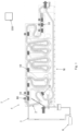
Figure 1 is a lateral view of a washing unit comprising a spraying system according to an example embodiment of the present invention. -
Figure 2 is a perspective view of a spraying bar according to an example embodiment of the present invention. -
Figure 3 is a lateral view of a portion of a sprinkling device having two spraying bars that are manipulated by portions of the conveyor. -
Figure 4 shows a sequence of operation of jets of fluid discharging from a shaft of the spraying bar as pockets carrying containers pass thereby. - The drawings illustrate only example embodiments and are therefore not to be considered limiting of the scope described herein, as other equally effective embodiments are within the scope and spirit of this disclosure. The elements and features shown in the drawings are not necessarily drawn to scale, emphasis instead being placed upon clearly illustrating the principles of the embodiments. Additionally, certain dimensions may be exaggerated to help visually convey certain principles. In the drawings, similar reference numerals between figures designate like or corresponding, but not necessarily the same, elements.
- In accordance with the purpose(s) of the present disclosure, as embodied and broadly described herein, embodiments of the present disclosure, in some aspects, relate to systems and methods incorporating diagnostic improvements to tunnel machines or bottle washing units.
- According to example embodiments, objects of the present invention comprise diagnostic systems and methods configured for use with a
washing unit 1 comprising at least one spraying system for discharging a liquid, gas and/or combination thereof (hereinafter "fluid") to contribute to the washing process containers 4 undergo as they travel throughout the washing unit along a chain orconveyor 2. -
Figure 1 shows thewashing unit 1 comprising theconveyor 2 for conveying containers 4 along an endless path W through a plurality of treatment zones as the containers move from an inlet station to an outlet station. In example embodiments, thewashing unit 1 comprises thespraying system 5 comprising a plurality ofsprinkling devices 10. In example embodiments, each of the treatment zones may comprise one or moresprinkling devices 10 positioned below the conveyor for discharging jets of the fluid for cleaning and further rinsing of the containers 4 as they are handled by theconveyor 2. In example embodiments, eachsprinkling device 10 comprises a pump for moving the fluid under low or high pressure to thesprinkling device 10, only one of which is shown inFigure 1 . Thus, thepump 6 is configured to service a singlesprinkling device 10 whereby a conduit 7 fluidly connects thepump 6 to thesprinkling device 10. - Still referring to
Figure 1 , a showering apparatus 80 may be provided and positioned above theconveyor 2 near some of thesprinkling devices 10, said showering apparatus 80 being generally fluidly connected to the conduit 7 and supplied with the fluid by thepump 6. Accordingly, in example embodiments, thepump 6 can be configured to supply fluid to a singlesprinkling device 10, or for example, may be configured to supply fluid to both the singlesprinkling device 10 and a single showering apparatus 80. In other example embodiments, one or moresprinkling devices 10 and/or showering apparatuses 80 may be supplied with fluid by a desired number of pumps, for example, by a single pump or by multiple pumps. -
Figure 2 shows thesprinkling device 10 is greater detail. In example embodiments, thesprinkling device 10 comprises at least onespraying bar 11, saidspraying bar 11 comprising apressure pipe 20 in which fluid flows, a rotatingshaft 30 extending along thepressure pipe 20, and at least one sprinkling means comprised of an aperture of thepressure pipe 20, anozzle 35 positioned in said aperture, between saidpressure pipe 20 and said rotatingshaft 30, and at least oneradial bore 40 in the rotatingshaft 30, located at the level of thenozzle 35, for receiving the fluid from thenozzle 35. According to example embodiments, thesprinkling device 10 may comprise 2, 3, 4 ormore spraying bars 11 arranged generally parallel relative to each other in a spaced-apart arrangement. For example, thesprinkling device 10 shown inFigure 3 comprises twospraying bars 11 which are at least partially spaced apart from each other. - With reference to
Figures 2-3 , amechanical cam 50 is provided at an end of the rotatingshaft 30, saidcam 50 being engaged directly or indirectly by the conveyor, in order to ensure that the jets of fluid, coming from theradial bores 40 and directed thereby, reaches the bottles moved by said conveyor. According to example embodiments, theconveyor 2 comprisespockets 3, each dedicated to receive a container 4. Furthermore, at least a portion of one ormore pockets 3 can be provided for engagement with themechanical cam 50 so as to provide for manipulation thereof to directly cause rotation of theshaft 30. In example embodiments, the speed of theconveyor 2 and rotation of themechanical cam 50 are synchronized so as to permit maximum engagement of the jets of fluid discharged from thebores 40 onto the containers 4. For example,Figure 4 shows a sequence of operation of theshaft 30 synchronized to rotate with the movement of the conveyor, showing the jets of fluid following thepocket 3 and a mouth of the container 4 as theconveyor 2 passes by thespraying bar 11. - According to example embodiments, jets of fluid are discharged from the
bores 40 for about 90 degrees of rotation of theshaft 30, for example about 45 degrees in either direction with respect to a vertical axis. According to other example embodiments, the range of rotation for which jets of fluid may be discharged may be greater than or less than 90 degrees. In example embodiments, theshaft 30 comprises pairs of spaced-apartbores 40 with one of the bores of the pair being generally oriented perpendicular relative to the other bore of the pair. Accordingly, still referring toFigure 4 , as one of the bores of the pair reaches the ending of the range of rotation for which the jet of fluid is spraying therefrom (see far right ofFigure 4 ), the other bore of the pair is entering the range of rotation, and thus defining a patterned discharge of jets of fluid. - As shown in
Figure 2 andFigure 4 , at least a portion of thesprinkling device 10 comprises at least onepressure sensor 60 connected therewith for monitoring a local pressure of the fluid that is delivered from thepump 6 to thesprinkling device 10 and one ormore spraying bars 11 thereof. In example embodiments, the at least onepressure sensor 60 may be in the form of a pressure transducer or other hardware component capable thereof. - In example embodiments, each
spraying bar 11 can comprise apressure sensor 60 connected thereto for monitoring the pressure of the fluid within thepressure pipe 20, or for example, near the delivery of the fluid to thepressure pipe 20. According to example embodiments, as a result of the arrangement of the rotatingbar 30 and bores 40 thereof defining the pattered discharge of jets of fluid, a pressure curve profile of the fluid at its delivery to thepressure pipe 20 of each sprayingbar 11 is obtainable and can be monitored in real time as the washing unit is in operation. - According to example embodiments of the present invention, a computing device such as a computer or other electronic device (e.g., programmable logic controller (PLC), etc.), for example a central processing unit (CPU) 100, which typically comprises a hard drive, a processor, random access memory, and hardware and software is configured to communicate with the
pressure sensors 60 in real time as thewashing unit 1 is operating. In example embodiments, data obtained by thepressure sensors 60 is continuously output to theCPU 100 in real time by a wired connection, or for example, wirelessly. The data received by theCPU 100 is then processed. - According to example embodiments, the data is processed by the
CPU 100 to determine a repetitive or repeating pressure profile over a span of time, for example, to understand the pressure of the fluid at its delivery to thespray bar 11 during normal operating conditions. Thereafter, once the repeating pressure profile is identified over a particular span of time, theCPU 100 continues to receive and process the data provided from thepressure sensor 60 while monitoring the repetitive profile. For example, according to example embodiments, it is during the monitoring of the repeating pressure profile that a variation of the profile is instantly recognizable, and an alert or alarm can be triggered when the variation is recognized to alert and inform an operator of the washing unit that a problem exists. Accordingly, problems or incidents may be attended to much sooner, making it less likely for an incident to result in a substantial repair and leading to less machine downtime with greater efficiency, while also mitigating risks linked to quality of washing or rinsing. - According to some example embodiments, said
CPU 100 or other electronic device(s) receiving and processing the data obtained from the one ormore sensors 60 of the plurality of sprinklingdevices 10 of thewashing machine 1 as described herein can be adapted for use with artificial intelligence (AI) or other AI driven software or capabilities to further improve, automate and streamline diagnostic capabilities. For example, an AI module can be implemented with the methods and systems as described herein so as to receive, process, learn, and exploit the data received from the one ormore sensors 60. And thus, over time, the AI module can become more knowledgeable with respect to the data so as to understand, recognize and make aware of not only current but also future potential failures. - According to another example embodiment of the present invention, the present invention relates to a method for detecting malfunction of a sprinkling
device 10 of awashing unit 1, said method comprising providing awashing unit 1 comprising at least one sprinklingdevice 10, at least onepump 6 configured for supplying the fluid under pressure to the sprinklingdevice 10, and a conduit 7 fluidly connected between the sprinklingunit 10 and the at least onepump 6, said method further comprising providing at least onesensor 60 for continuously measuring the pressure of the fluid within the conduit 7 or at delivery or the fluid to the sprinklingdevice 10, obtaining data from thesensor 60, processing the data to determine a repetitive pressure profile, monitoring the repetitive pressure profile, and triggering an alarm when variation exists in the repetitive pressure profile. In example embodiments, said at least one pump is configured for supplying the fluid under pressure to the sprinklingdevice 10, and more specifically one or more spray bars 11 thereof. As described above, thesensor 60 can be installed for fluid communication with the fluid within thepressure pipe 20, to obtain a more proximal pressure relative to the fluid's output, and thus obtain more credible and accurate readings of the pressure within thepressure pipe 20, continuously and in real time, as theshaft 30 rotates atop thenozzles 35 to permit a patterned discharge of jets of fluid from thepressure pipe 20, through thenozzles 35 and through thebores 40. - In example embodiments, the
washing unit 1 can comprise a plurality of sprinklingdevices 10 and wherein the method can further comprise equipping each sprinklingdevice 10 with at least onesensor 60 so as to obtain and process the data thereof, continuously, so as to determine and monitor the repetitive pressure profile of eachsensor 60. According to example embodiments, the method as described herein can further comprise providing a plurality of sprinklingdevices 10, said method further providing an indication of possible mechanical errors associated with the variations found in the repetitive pressure profiles of one ormore sensors 60 of the plurality of sprinklingdevices 10. According to example embodiments, variations remaining specific to data obtained from asingle sprinkling device 10 indicates failure of the sprinklingdevice 10 itself and wherein variations of data moving between two or more of the plurality of sprinklingdevices 10 indicates a failure of the conveyor or components thereof such as a triggering arm according to one example embodiment. For example, when a variation occurs in a repetitive pressure profile and the variation does not disappear, then the behavior is likely indicative of a failure of the sprinklingdevice 10 for which the data is obtained. Whereas, when a variation in the repetitive pressure profile only occurs for a period of time, and wherein said variation is moving from one repetitive pressure profile to the next, from one sprinklingdevice 10 to thenext sprinkling device 10, then the behavior is likely indicative of a failure of the conveyor or one or more trigger arms, for example wherein the variation is typically coinciding with the damaged portion thereof as it moves along throughout thewashing machine 1. - While specific embodiments of the invention have been described in detail, it will be appreciated by those skilled in the art that various modifications and alternatives to those details, in addition to those discussed above, could be developed in light of the overall teachings of the disclosure. Accordingly, the particular arrangements disclosed are meant to be illustrative only, and not limiting as to the scope of the invention which is to be given the full breadth of the claims appended in any and all equivalents thereof, including any combination of their features.
Claims (16)
- A method for detecting malfunction of a sprinkling device 10 of a washing unit 1, the method comprising:providing a washing unit 1 comprising at least one sprinkling device 10, at least one pump 6 configured for supplying the fluid under pressure to the sprinkling device 10, and a conduit 7 fluidly connected between the sprinkling unit 10 and the at least one pump 6;providing at least one sensor 60 for continuously measuring the pressure of the fluid within the conduit 7 or at delivery of the fluid to the sprinkling device 10;obtaining data from the at least one sensor 60;processing the data to determine a repetitive pressure profile;monitoring the repetitive pressure profile; andtriggering an alarm when variation exists in the repetitive pressure profile.
- The method of Claim 1, wherein the at least one pump is configured for supplying the fluid under pressure to one or more spray bars 11 of the sprinkling device 10.
- The method of Claim 1, wherein each of the one or more spray bars 11 comprises at least one sensor 60 connected thereto and in communication with the pressurized fluid contained therein.
- The method of Claim 3, wherein each spray bar 11 comprises a pressure pipe 20, and wherein the at least on sensor 60 is connected thereto and in communication with the pressurized fluid contained therein.
- The method of Claim 1, wherein the washing unit 1 comprises a plurality of sprinkling devices 10 and wherein each of the plurality sprinkling devices 10 comprise at least one sensor 60.
- The method of Claim 5, further comprising obtaining data from the plurality of sensors 60.
- The method of Claim 6, further comprising processing the data to determine a repetitive pressure profile for each of the plurality of sensors 60.
- The method of Claim 7, further comprising monitoring the repetitive pressure profiles for each of the plurality of sensors 60.
- The method of Claim 8, further comprising triggering an alarm when a variation exists in one or more of the repetitive pressure profiles of the plurality of sensors 60.
- The method according to any of Claim 1-9, wherein the sensor 60 comprises a pressure transducer.
- The method according to any of Claim 1-9, wherein the washing unit 1 comprises a plurality of sprinkling devices 10, and wherein the method further comprises providing indication of possible mechanical errors associated with the variations found in the repetitive pressure profile.
- The method of Claim 11, wherein variations remaining specific to data obtained from a single sprinkling device 10 indicates failure of the sprinkling device 10 itself and wherein variations of data moving between two or more of the plurality of sprinkling devices 10 indicates a failure of the conveyor or components thereof.
- A sprinkling device 10 according to the method of Claim 1, said sprinkling device comprising:at least one spraying bar 11, said at least one spraying bar 11 comprising a pressure pipe 20 and a shaft 30 rotationally mounted to the pressure pipe 20; andat least one sensor 60 connected to the pressure pipe 20.
- The sprinkling device of Claim 13, wherein the at least one sensor 60 comprises a pressure transducer.
- The sprinkling device of Claim 14, wherein the pressure transducer comprises a wired connection with a CPU 100 for collecting, processing and monitoring data that is output from the pressure transducer.
- The sprinkling device of Claim 14, wherein the pressure transducer comprises a wireless connection with a CPU 100 for collecting, processing and monitoring data that is output from the pressure transducer.
Priority Applications (1)
| Application Number | Priority Date | Filing Date | Title |
|---|---|---|---|
| EP23220446.1A EP4578563A1 (en) | 2023-12-28 | 2023-12-28 | Spraying system diagnostics and methods thereof |
Applications Claiming Priority (1)
| Application Number | Priority Date | Filing Date | Title |
|---|---|---|---|
| EP23220446.1A EP4578563A1 (en) | 2023-12-28 | 2023-12-28 | Spraying system diagnostics and methods thereof |
Publications (1)
| Publication Number | Publication Date |
|---|---|
| EP4578563A1 true EP4578563A1 (en) | 2025-07-02 |
Family
ID=89474088
Family Applications (1)
| Application Number | Title | Priority Date | Filing Date |
|---|---|---|---|
| EP23220446.1A Pending EP4578563A1 (en) | 2023-12-28 | 2023-12-28 | Spraying system diagnostics and methods thereof |
Country Status (1)
| Country | Link |
|---|---|
| EP (1) | EP4578563A1 (en) |
Citations (4)
| Publication number | Priority date | Publication date | Assignee | Title |
|---|---|---|---|---|
| EP0634230A1 (en) * | 1993-07-12 | 1995-01-18 | PepsiCo, Inc. | High speed bottle washing machine and nozzle spray assembly |
| US20070239371A1 (en) * | 2005-10-17 | 2007-10-11 | I F M Electronic Gmbh | Process, sensor and diagnosis device for pump diagnosis |
| WO2011027370A1 (en) * | 2009-09-02 | 2011-03-10 | Sidel S.P.A. | Rinsing machine for containers, in particular bottles |
| EP3124128A1 (en) | 2015-07-30 | 2017-02-01 | Gebo Packaging Solutions Italy SRL | Sprinkling device and corresponding washing unit |
-
2023
- 2023-12-28 EP EP23220446.1A patent/EP4578563A1/en active Pending
Patent Citations (4)
| Publication number | Priority date | Publication date | Assignee | Title |
|---|---|---|---|---|
| EP0634230A1 (en) * | 1993-07-12 | 1995-01-18 | PepsiCo, Inc. | High speed bottle washing machine and nozzle spray assembly |
| US20070239371A1 (en) * | 2005-10-17 | 2007-10-11 | I F M Electronic Gmbh | Process, sensor and diagnosis device for pump diagnosis |
| WO2011027370A1 (en) * | 2009-09-02 | 2011-03-10 | Sidel S.P.A. | Rinsing machine for containers, in particular bottles |
| EP3124128A1 (en) | 2015-07-30 | 2017-02-01 | Gebo Packaging Solutions Italy SRL | Sprinkling device and corresponding washing unit |
Similar Documents
| Publication | Publication Date | Title |
|---|---|---|
| US9381663B2 (en) | Method for drilling at least one hole into a workpiece | |
| JP4938744B2 (en) | Water cleaning apparatus and cleaning method for gas turbine compressor | |
| CN105940197B (en) | Diesel exhaust gas fluid filter permeability inspection policies and the machine for using this strategy | |
| JP6109857B2 (en) | Liquid discharge system monitoring | |
| CN107427866A (en) | Clean the method and cleaning equipment of workpiece and/or mechanical component for machine | |
| EP0634230A1 (en) | High speed bottle washing machine and nozzle spray assembly | |
| CN102612413B (en) | Rinsing machine for containers | |
| US20050210619A1 (en) | Pipeline surface preparation for inspection with debris collection | |
| AU2018101375B4 (en) | Device for sampling material from moving belt conveyor | |
| CN103246269A (en) | Comprehensive monitoring device for conveying chain of coal sorting machine | |
| CN109292943B (en) | Wastewater PH control device and wastewater treatment system | |
| JP4307365B2 (en) | Tank equipment with cleaning verification system | |
| JP5878049B2 (en) | Chemical injection device | |
| JP5645531B2 (en) | Cooling liquid supply confirmation device for induction heating apparatus and cooling liquid supply confirmation method | |
| WO2016050604A1 (en) | Monitoring system for annuar scrubbers | |
| CN216590991U (en) | Oil supply device | |
| CN104003143B (en) | Method for cleaning span line | |
| CN210171163U (en) | Chemical tail gas treatment equipment | |
| JP5066997B2 (en) | Cleaning device | |
| CN220222442U (en) | Belt tearing detection device with cleaning function | |
| CN221519111U (en) | Fault detection alarm device of ink jet printer | |
| KR20110072785A (en) | Wire rod guide device | |
| CN218945858U (en) | Online cleaning device of roller equipment | |
| CN121358697A (en) | Equipment for increasing the dry matter content of flowable media and methods for monitoring equipment performance. | |
| CN223493601U (en) | Drainage system and wire cutting device thereof |
Legal Events
| Date | Code | Title | Description |
|---|---|---|---|
| PUAI | Public reference made under article 153(3) epc to a published international application that has entered the european phase |
Free format text: ORIGINAL CODE: 0009012 |
|
| STAA | Information on the status of an ep patent application or granted ep patent |
Free format text: STATUS: THE APPLICATION HAS BEEN PUBLISHED |
|
| AK | Designated contracting states |
Kind code of ref document: A1 Designated state(s): AL AT BE BG CH CY CZ DE DK EE ES FI FR GB GR HR HU IE IS IT LI LT LU LV MC ME MK MT NL NO PL PT RO RS SE SI SK SM TR |
|
| STAA | Information on the status of an ep patent application or granted ep patent |
Free format text: STATUS: THE APPLICATION IS DEEMED TO BE WITHDRAWN |