EP4578548A1 - Uniaxial coupling device - Google Patents
Uniaxial coupling device Download PDFInfo
- Publication number
- EP4578548A1 EP4578548A1 EP23220391.9A EP23220391A EP4578548A1 EP 4578548 A1 EP4578548 A1 EP 4578548A1 EP 23220391 A EP23220391 A EP 23220391A EP 4578548 A1 EP4578548 A1 EP 4578548A1
- Authority
- EP
- European Patent Office
- Prior art keywords
- head
- connector
- holder
- uniaxial
- coupling
- Prior art date
- Legal status (The legal status is an assumption and is not a legal conclusion. Google has not performed a legal analysis and makes no representation as to the accuracy of the status listed.)
- Granted
Links
Images

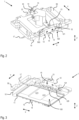

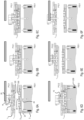


Classifications
-
- B—PERFORMING OPERATIONS; TRANSPORTING
- B01—PHYSICAL OR CHEMICAL PROCESSES OR APPARATUS IN GENERAL
- B01L—CHEMICAL OR PHYSICAL LABORATORY APPARATUS FOR GENERAL USE
- B01L3/00—Containers or dishes for laboratory use, e.g. laboratory glassware; Droppers
- B01L3/56—Labware specially adapted for transferring fluids
- B01L3/563—Joints or fittings; Separable fluid transfer means to transfer fluids between at least two containers, e.g. connectors
-
- B—PERFORMING OPERATIONS; TRANSPORTING
- B01—PHYSICAL OR CHEMICAL PROCESSES OR APPARATUS IN GENERAL
- B01L—CHEMICAL OR PHYSICAL LABORATORY APPARATUS FOR GENERAL USE
- B01L3/00—Containers or dishes for laboratory use, e.g. laboratory glassware; Droppers
- B01L3/02—Burettes; Pipettes
- B01L3/0203—Burettes, i.e. for withdrawing and redistributing liquids through different conduits
-
- B—PERFORMING OPERATIONS; TRANSPORTING
- B01—PHYSICAL OR CHEMICAL PROCESSES OR APPARATUS IN GENERAL
- B01L—CHEMICAL OR PHYSICAL LABORATORY APPARATUS FOR GENERAL USE
- B01L3/00—Containers or dishes for laboratory use, e.g. laboratory glassware; Droppers
- B01L3/50—Containers for the purpose of retaining a material to be analysed, e.g. test tubes
- B01L3/502—Containers for the purpose of retaining a material to be analysed, e.g. test tubes with fluid transport, e.g. in multi-compartment structures
- B01L3/5025—Containers for the purpose of retaining a material to be analysed, e.g. test tubes with fluid transport, e.g. in multi-compartment structures for parallel transport of multiple samples
- B01L3/50255—Multi-well filtration
-
- G—PHYSICS
- G01—MEASURING; TESTING
- G01N—INVESTIGATING OR ANALYSING MATERIALS BY DETERMINING THEIR CHEMICAL OR PHYSICAL PROPERTIES
- G01N35/00—Automatic analysis not limited to methods or materials provided for in any single one of groups G01N1/00 - G01N33/00; Handling materials therefor
- G01N35/10—Devices for transferring samples or any liquids to, in, or from, the analysis apparatus, e.g. suction devices, injection devices
- G01N35/1065—Multiple transfer devices
- G01N35/1074—Multiple transfer devices arranged in a two-dimensional array
-
- G—PHYSICS
- G01—MEASURING; TESTING
- G01N—INVESTIGATING OR ANALYSING MATERIALS BY DETERMINING THEIR CHEMICAL OR PHYSICAL PROPERTIES
- G01N35/00—Automatic analysis not limited to methods or materials provided for in any single one of groups G01N1/00 - G01N33/00; Handling materials therefor
- G01N35/10—Devices for transferring samples or any liquids to, in, or from, the analysis apparatus, e.g. suction devices, injection devices
- G01N35/1081—Devices for transferring samples or any liquids to, in, or from, the analysis apparatus, e.g. suction devices, injection devices characterised by the means for relatively moving the transfer device and the containers in an horizontal plane
- G01N35/1083—Devices for transferring samples or any liquids to, in, or from, the analysis apparatus, e.g. suction devices, injection devices characterised by the means for relatively moving the transfer device and the containers in an horizontal plane with one horizontal degree of freedom
-
- B—PERFORMING OPERATIONS; TRANSPORTING
- B01—PHYSICAL OR CHEMICAL PROCESSES OR APPARATUS IN GENERAL
- B01L—CHEMICAL OR PHYSICAL LABORATORY APPARATUS FOR GENERAL USE
- B01L2200/00—Solutions for specific problems relating to chemical or physical laboratory apparatus
- B01L2200/02—Adapting objects or devices to another
- B01L2200/025—Align devices or objects to ensure defined positions relative to each other
-
- B—PERFORMING OPERATIONS; TRANSPORTING
- B01—PHYSICAL OR CHEMICAL PROCESSES OR APPARATUS IN GENERAL
- B01L—CHEMICAL OR PHYSICAL LABORATORY APPARATUS FOR GENERAL USE
- B01L2200/00—Solutions for specific problems relating to chemical or physical laboratory apparatus
- B01L2200/02—Adapting objects or devices to another
- B01L2200/026—Fluid interfacing between devices or objects, e.g. connectors, inlet details
-
- B—PERFORMING OPERATIONS; TRANSPORTING
- B01—PHYSICAL OR CHEMICAL PROCESSES OR APPARATUS IN GENERAL
- B01L—CHEMICAL OR PHYSICAL LABORATORY APPARATUS FOR GENERAL USE
- B01L2200/00—Solutions for specific problems relating to chemical or physical laboratory apparatus
- B01L2200/16—Reagents, handling or storing thereof
-
- B—PERFORMING OPERATIONS; TRANSPORTING
- B01—PHYSICAL OR CHEMICAL PROCESSES OR APPARATUS IN GENERAL
- B01L—CHEMICAL OR PHYSICAL LABORATORY APPARATUS FOR GENERAL USE
- B01L2300/00—Additional constructional details
- B01L2300/06—Auxiliary integrated devices, integrated components
- B01L2300/0681—Filter
-
- B—PERFORMING OPERATIONS; TRANSPORTING
- B01—PHYSICAL OR CHEMICAL PROCESSES OR APPARATUS IN GENERAL
- B01L—CHEMICAL OR PHYSICAL LABORATORY APPARATUS FOR GENERAL USE
- B01L2300/00—Additional constructional details
- B01L2300/08—Geometry, shape and general structure
- B01L2300/0809—Geometry, shape and general structure rectangular shaped
- B01L2300/0829—Multi-well plates; Microtitration plates
-
- B—PERFORMING OPERATIONS; TRANSPORTING
- B01—PHYSICAL OR CHEMICAL PROCESSES OR APPARATUS IN GENERAL
- B01L—CHEMICAL OR PHYSICAL LABORATORY APPARATUS FOR GENERAL USE
- B01L2400/00—Moving or stopping fluids
- B01L2400/04—Moving fluids with specific forces or mechanical means
- B01L2400/0475—Moving fluids with specific forces or mechanical means specific mechanical means and fluid pressure
- B01L2400/0487—Moving fluids with specific forces or mechanical means specific mechanical means and fluid pressure fluid pressure, pneumatics
-
- B—PERFORMING OPERATIONS; TRANSPORTING
- B01—PHYSICAL OR CHEMICAL PROCESSES OR APPARATUS IN GENERAL
- B01L—CHEMICAL OR PHYSICAL LABORATORY APPARATUS FOR GENERAL USE
- B01L3/00—Containers or dishes for laboratory use, e.g. laboratory glassware; Droppers
- B01L3/02—Burettes; Pipettes
- B01L3/021—Pipettes, i.e. with only one conduit for withdrawing and redistributing liquids
Definitions
- the current invention relates to a uniaxial coupling device, a uniaxial coupling apparatus with said uniaxial coupling device, a uniaxial coupling arrangement with said uniaxial coupling device and an attachment to be coupled therewith and a method for coupling the attachment with said uniaxial coupling device.
- uniaxial coupling devices comprise mechanical coupling elements with actuators to realize or release a form-fit connection.
- Such devices are expensive to manufacture and maintain, they take up more space due to the required actuators and they require more programming.
- a uniaxial coupling device comprises a head and a holder that are movable relative to each other in a single direction, and at least one first abutment and at least one second abutment that are stationary with respect to the holder.
- said single direction is a vertical direction.
- said single direction could also be a horizontal direction or a direction at an angle greater zero with respect to the vertical direction or the horizontal direction.
- the holder is aligned with the head in said single direction.
- the head comprises at least one connector that is displaceable in said single direction between a first position and a second position, wherein with respect to the head, the first position is closer to the holder than the second position.
- there are two connectors only one or three or four connectors are also possible.
- the at least one connector comprises at least one first coupling surface on a side facing the holder.
- the holder comprises at least one reception for receiving an attachment to be coupled to the head.
- the at least one reception is displaceable in said single direction between a first position and a second position, wherein with respect to the holder, the first position is closer to the head than the second position.
- the distance between the first position of the at least one connector and the second position of the at least one connector corresponds to the distance between the first position of the reception and the second position of the reception.
- the at least one connector is aligned with the at least one first abutment in said single direction.
- the at least one first abutment is arranged on a side of the holder facing the head.
- the at least one second abutment is arranged on a side of the connector facing away from the holder and is aligned with the at least one connector in said single direction.
- the at least one first coupling surface abuts a corresponding at least one second coupling surface of the attachment, while the at least one connector abuts the at least one first abutment, when the at least one connector is in its first position and when the reception is in its first position, and the at least one first coupling surface is spaced apart from the corresponding at least one second coupling surface of the attachment while the at least one connector abuts the at least one first abutment, when the at least one connector is in its second position and when the reception is in its second position.
- One of the at least one first coupling surface and the at least one second coupling surface belongs to a magnetic element and the other belongs to a magnetizable element or both belong to a magnetic element.
- Such a uniaxial coupling device has the advantage that there is no actuator needed for coupling or uncoupling an attachment to the head.
- the absence of an actuator enables a compact design.
- the at least one first coupling surface belongs to a magnetizable element and the at least one second coupling surface belongs to a magnetic element.
- the at least one first coupling surface belongs to a magnetic element and the at least one second coupling surface belongs to a magnetizable element.
- the at least one first coupling surface and the at least one second coupling surface are essentially perpendicular to said single direction.
- the at least one connector comprises at least one elevation extending towards the holder in said single direction, and wherein the first coupling surface is a face of said at least one elevation.
- the at least one connector comprises two, three, four or more elevations and an equal number of first coupling surfaces.
- the head comprises a plate that extends essentially perpendicular to said single direction. Usually, the plate extends in horizontal directions.
- the at least one connector is displaceable mounted with a connector rail extending in said single direction.
- the connector rail is mounted displaceable to the plate by means of at least one connector guide.
- the at least one connector guide is a bush bearing.
- there are two connector guides at each connector wherein in said single direction, one connector guide is arranged on one side of the connector and one connector guide is arranged on a side opposite thereto.
- the connector rail protrudes above the at least one first coupling surface in the direction of the holder.
- the connector rail comprises a straight bar with a circular cross-section.
- Straight bars with other cross-section shapes are also possible.
- straight bars with polygonal cross-sections such as tringle, square, rectangle, pentagon, or hexagon.
- Polygonal cross-sections prevent unintentional rotation around the longitudinal axis of the bars.
- the head comprises at least one detent element with which the connector is detachably lockable in its first position and its second position.
- detent elements such as ball flycatchers or detent pins can be used.
- the at least one detent element is arranged on the plate and a corresponding snap-in recess is arranged on the at least one connector.
- the at least one detent element is arranged on the at least one connector and the corresponding snap-in recess is arranged on the at least one connector.
- the at least one connector is arranged in a laterally peripheral region of the head. Usually, on a lateral horizontal side of the head.
- one connector is arranged on one lateral side of the head and one connector is arranged on a lateral opposite side thereof.
- the holder comprises a housing with at least one blind hole whose longitudinal axis is parallel to said single direction.
- the reception comprises at least one pin that is arranged in the at least one blind hole and that is pushed from its second position towards its first position by a resilient element.
- the resilient element can be a compression spring.
- the at least one pin comprises a circular cross-section.
- the housing comprises at least one recess facing the head and respective side walls surrounding the at least one recess, and the at least one blind hole is arranged in one of the side walls, its opening facing the head.
- the at least one blind hole is arranged in one of the side walls, its opening facing the head.
- the at least one first abutment comprises a straight bar with a circular cross-section.
- the at least one first abutment protrudes above the at least one reception in its first position in the direction of the head.
- At least one lift rail is arranged on one lateral side of the base plate and at least one lift rail is arranged on a lateral opposite side thereof.
- two lift rails are arranged on one lateral side of the base plate and wherein two lift rails are arranged on the lateral opposite side thereof.
- the first lift comprises at least one first spindle that is arranged on one lateral side of the base plate and that is operatively connected to the first drive. If there are two first spindles, one first spindle is arranged on one lateral side of the base plate and one first spindle is arranged on a lateral opposite side thereof.
- a first belt operatively connects all first spindles to the first drive.
- the lateral sides of the lift rails and the lateral sides of the first spindles can be oriented in the first horizontal direction.
- a shuttle with a carrier is provided on the base plate, wherein the carrier is movable in a direction perpendicular to said single direction, from a first station between the base plate and the first platform to a second station in an area outside of a projection of the first platform in said single direction.
- the shuttle comprises a carrier) that is movable with a shuttle drive and that is guided by at least one shuttle rail. If there are two shuttle rails, one shuttle rail is provided on one lateral side of the base plate and one shuttle rail is provided on one lateral opposite side thereof.
- the at least one shuttle rail can be formed integrally in a single piece with the base plate.
- a shuttle belt operatively connects the carrier to the shuttle drive.
- the carrier is movable in the second horizontal direction.
- the first platform comprises a first part and a second part that are arranged next to each other in the second horizontal direction, wherein the first part or the second part of the first platform comprises a reception for the head.
- the first part of the first platform can be further away from the second station of the carrier of the shuttle.
- the first part of the first platform comprises a reception for the head.
- the first part of the first platform comprises a first gas connection and wherein the second part of the first platform comprises a second gas connection.
- the first gas connection and the second gas connection can be connected to the same gas tank or to different gas tanks with different gases.
- one gas can be dry nitrogen, and the other gas can be dry air.
- At least one of the gases can be warm, and can have a temperature in the range of 10°C to 90°C, preferably 20°C to 80°C.
- the uniaxial coupling apparatus further comprising a second lift that comprises at least one second platform that is moveable with a second drive and wherein the at least one second platform is guided by the same at least one lift rail as the first platform of the first lift.
- the second lift is arranged between the second part of the first platform and the base plate. If there are two second platforms, one second platform is arranged on one lateral side of the base plate and one second platform is arranged on the lateral opposite side thereof.
- the second lift comprises at least one second spindle that is arranged on one lateral side of the base plate, next to the at least one first spindle and wherein the at least one second spindle is operatively connected to the second drive.
- one second spindle is arranged on one lateral side of the base plate and one second spindle is arranged on the lateral opposite side thereof.
- a second belt can operatively connect all second spindles to the second drive.
- a top plate is provided on a side of the at least one first lift rail opposite to the base plate, wherein the top plate is parallel to the base plate.
- the at least one second abutment is arranged on a side of the top plate facing the base plate or wherein the second abutment is formed integrally in a single piece with the top plate on a side facing the base plate.
- the uniaxial coupling apparatus further comprising a housing that encloses at least the base plate and the top plate, wherein an opening is provided on one side of the housing allowing the movement of the shuttle through said opening from the first station inside the housing to the second station outside of the housing.
- a window can be provided in a lateral side of the housing.
- a suction connection can be provided at the housing. At the suction connection, a negative pressure can be applied for removing steam and/or gas from the inside of the housing.
- the uniaxial coupling apparatus further comprising a transfer unit with a motor driven X-axis and/or a motor driven Y-axis and a motor driven Z-axis that allows an alignment of a transfer unit head with the second station of the shuttle in said single direction.
- the transfer unit can be a pipetting robot with a pipetting head.
- the uniaxial coupling apparatus further comprising a machine base, wherein the base plate is arranged on the machine base or wherein the base plate and the transfer unit are arranged on the machine base.
- a Uniaxial coupling arrangement comprising a uniaxial coupling device according to one of the previously mentioned embodiments of the uniaxial coupling device or the uniaxial coupling apparatus and an attachment that is arranged between the head and the holder.
- the number of second coupling surfaces is identical to the number of first coupling surfaces and wherein the lateral positions of the second coupling surfaces are identical to the lateral positions of the corresponding first surfaces.
- the attachment comprises a plate-shaped body with a surface facing the head that is complementary to a corresponding surface of the head facing the attachment.
- the at least one second coupling surface can be arranged in a laterally peripheral region of the attachment. In the case of two or more second coupling surfaces, at least one second coupling surface is arranged on one lateral side of the attachment and at least one second coupling surface is arranged on a lateral opposite side thereof.
- At least one through hole for the at least one first abutment is arranged in the laterally peripheral region of the attachment.
- the at least one through hole can be arranged in the middle of two neighbouring second coupling surfaces. If there are two through holes, one through hole is arranged on one lateral side of the attachment and one through hole is arranged on a lateral opposite side thereof.
- the attachment comprises a closed circumferential frame that comprises the laterally peripheral region.
- the at least one second coupling surface can be flush with its surrounding surface.
- Figure 1 shows a sectional view through a uniaxial coupling device according to the invention. It comprises a head 1 and a holder 2 that are movable relative to each other in a single direction Z, and at least one first abutment 24 that is stationary with respect to the holder 2.
- the head 1 comprises a plate 10 that extends perpendicular to the single direction, i.e., in the vertical direction Z.
- the plate 10 comprises a closed circumferential collar 11 for receiving an attachment 3 with a plate-shaped body 30 that extends perpendicular to the vertical direction Z and that has a recess that is complementary to the collar 11.
- the head 1 comprises two connectors 12 that are displaceable in said vertical direction Z between a first position P12.1 and a second position P12.2, wherein with respect to the head 1, the first position P12.1 is closer to the holder 2 than the second position P12.2.
- the connectors 12 are beam-shaped and comprise four first coupling surfaces 120 on a side facing the holder 2.
- the first coupling surfaces 120 are distributed over the length of the connectors 12 and are arranged on elevations 121 that extend in said vertical direction Z towards the holder 2.
- One connector rail 14 is fixed to a central part of each connector 12.
- the connector rail 14 is pin-shaped an extends in said vertical direction Z over the connector 12 on a side of the first coupling surfaces 120 and on a side opposite thereof.
- Each connector rail 14 is slidably mounted to the plate 10 by means of connector guides 13.
- Each connector 12 comprises detent elements 15 with which, the connectors 12 can be releasably clamped in the first position P12.1 and in the second position P12.2.
- the holder 2 is aligned with the head 1 in said vertical direction Z.
- the holder 2 comprises four receptions 23 for an attachment 3 to be coupled to the head 1, said four receptions 23 being displaceable in said vertical direction Z between a first position P23.1 and a second position P23.2, wherein with respect to the holder 2, the first position P23.1 is closer to the head 1 than the second position P23.2.
- the receptions 23 are pins and are arranged in blind holes 200 in the corners of a frame-shaped housing 20 of the holder 2 together with compression springs 230.
- the pins 23 are prevented from escaping the blind holes 200 by retainers 231.
- the distance between the first position P12.1 of the connectors 12 and their second positions P12.2 corresponds to the distance between the first position P23.1 of the receptions 23 and their second position P23.2.
- Each of the two connectors 12 is aligned with one corresponding first abutment 24 in said vertical direction Z.
- the first abutments 24 are arranged on a side of the holder 2 facing the head 1.
- the first abutments 24 are pins that are arranged in the middle between two neighbouring first receptions 23.
- the first coupling surfaces 120 of the connectors 12 abut corresponding second coupling surfaces 330 of the attachment 3, while the connectors 12 abut the first abutments 24, when the connectors 12 are in their first positions P12.1 and when the receptions 23 are in their first positions P23.1, and the first coupling surfaces 120 are spaced apart from the second coupling surfaces 330 while the connectors 12 abut the first abutments 24, when the connectors 12 are in their second positions P12.2 and when the receptions 23 are in their second positions P23.2.
- the connectors 12 are made from a magnetizable material and the second coupling surfaces 330 belong to magnets 33 that are embedded in the body 30 of the attachment 3.
- a common second abutment 25 is arranged on a side of the connectors 12 facing away from the holder 2. The second abutment 25 is stationary with respect to the holder 2 and is aligned with the connectors 12 in said vertical direction Z.
- Figure 2 shows a perspective top view of the head 1 of the uniaxial coupling device of figure 1 and figure 3 shows a perspective bottom view of the head 1.
- a pressure connection 16 is provided on the upper side of the plate 10.
- a recess 100 is provided on the opposite lower side of the plate 10.
- a pressure sensor 17 is provided to register the pressure within the recess 100 of the plate 10.
- the head 1 is fixed to a first platform 50 of a first lift which is shown in figure 7 .
- the connectors 12 are arranged on two opposite lateral sides of the plate 10.
- Each connector 12 is fixed to a pin-shaped connector rail 14 that is slidable mounted to the plate 10 by means of two bush bearings 13 that are arranged on both free ends of the connector rail 14. To prevent a tilting of the connectors 12 around the vertical axis Z of the connector rail 14, the connectors 12 laterally abut a side of the plate 10.
- Each connector 12 comprises two resilient thrust pieces or snap shots as detent elements 15 that can releasably engage grooves 500 in a lateral side of the first platform 50 facing the connectors 12.
- the first platform 50 is mounted to the two spindles 51 by means of spindle nuts 510, allowing a movement of the platform 50 in the vertical direction Z, when the first spindles 51 are rotated.
- the rotation of the two first spindles 51 is synchronized by a first belt 52 and can be effected by a first drive 53.
- the first belt 52 and the first drive 53 are mounted on the top plate 41.
- the head 1 is mounted on the first platform 50 and a part of the top plate 41 that is in the projection of the vertical direction Z above the connectors 12 forms the second abutment plate 25.
- a shuttle 6 is arranged on the base plate 40.
- the uniaxial coupling apparatus 4 is arranged on a machine base 9 together with a transfer unit 8.
- the transfer unit 8 comprises an X-axis 80, a Y-axis 80 and a Z-axis 82, allowing the special movement of a transfer unit head 83 in a space around the uniaxial coupling apparatus 4.
- the transfer unit head 83 is a pipetting head which enables the transfer of liquids.
Landscapes
- Health & Medical Sciences (AREA)
- Chemical & Material Sciences (AREA)
- Clinical Laboratory Science (AREA)
- Chemical Kinetics & Catalysis (AREA)
- Analytical Chemistry (AREA)
- General Health & Medical Sciences (AREA)
- Biochemistry (AREA)
- Physics & Mathematics (AREA)
- Life Sciences & Earth Sciences (AREA)
- General Physics & Mathematics (AREA)
- Immunology (AREA)
- Pathology (AREA)
- Hematology (AREA)
- Details Of Connecting Devices For Male And Female Coupling (AREA)
- Automatic Analysis And Handling Materials Therefor (AREA)
Abstract
Description
- The current invention relates to a uniaxial coupling device, a uniaxial coupling apparatus with said uniaxial coupling device, a uniaxial coupling arrangement with said uniaxial coupling device and an attachment to be coupled therewith and a method for coupling the attachment with said uniaxial coupling device.
- Known embodiments of such uniaxial coupling devices comprise mechanical coupling elements with actuators to realize or release a form-fit connection. Such devices are expensive to manufacture and maintain, they take up more space due to the required actuators and they require more programming.
- It is a task of current invention to provide a uniaxial coupling device that does not require actuators for coupling or uncoupling.
- This task is solved by a uniaxial coupling device with the features of
claim 1. Further embodiments of the uniaxial coupling device, a uniaxial coupling apparatus, a uniaxial coupling arrangement, as well as a method for coupling an attachment and a head of a uniaxial coupling device are defined by the features of further claims. - A uniaxial coupling device according to the invention comprises a head and a holder that are movable relative to each other in a single direction, and at least one first abutment and at least one second abutment that are stationary with respect to the holder. Usually, said single direction is a vertical direction. However, said single direction could also be a horizontal direction or a direction at an angle greater zero with respect to the vertical direction or the horizontal direction. The holder is aligned with the head in said single direction. The head comprises at least one connector that is displaceable in said single direction between a first position and a second position, wherein with respect to the head, the first position is closer to the holder than the second position. Usually, there are two connectors, only one or three or four connectors are also possible. The at least one connector comprises at least one first coupling surface on a side facing the holder. The holder comprises at least one reception for receiving an attachment to be coupled to the head. The at least one reception is displaceable in said single direction between a first position and a second position, wherein with respect to the holder, the first position is closer to the head than the second position. The distance between the first position of the at least one connector and the second position of the at least one connector corresponds to the distance between the first position of the reception and the second position of the reception. The at least one connector is aligned with the at least one first abutment in said single direction. The at least one first abutment is arranged on a side of the holder facing the head. The at least one second abutment is arranged on a side of the connector facing away from the holder and is aligned with the at least one connector in said single direction. When an attachment is arranged on the reception, the at least one first coupling surface abuts a corresponding at least one second coupling surface of the attachment, while the at least one connector abuts the at least one first abutment, when the at least one connector is in its first position and when the reception is in its first position, and the at least one first coupling surface is spaced apart from the corresponding at least one second coupling surface of the attachment while the at least one connector abuts the at least one first abutment, when the at least one connector is in its second position and when the reception is in its second position. One of the at least one first coupling surface and the at least one second coupling surface belongs to a magnetic element and the other belongs to a magnetizable element or both belong to a magnetic element.
- Such a uniaxial coupling device has the advantage that there is no actuator needed for coupling or uncoupling an attachment to the head. The absence of an actuator enables a compact design.
- In one embodiment, the at least one first coupling surface belongs to a magnetizable element and the at least one second coupling surface belongs to a magnetic element. Alternatively, the at least one first coupling surface belongs to a magnetic element and the at least one second coupling surface belongs to a magnetizable element.
- In one embodiment, the at least one first coupling surface and the at least one second coupling surface are essentially perpendicular to said single direction.
- In one embodiment, the at least one connector comprises at least one elevation extending towards the holder in said single direction, and wherein the first coupling surface is a face of said at least one elevation.
- In one embodiment, the at least one connector comprises two, three, four or more elevations and an equal number of first coupling surfaces.
- In one embodiment, the head comprises a plate that extends essentially perpendicular to said single direction. Usually, the plate extends in horizontal directions. On the plate, the at least one connector is displaceable mounted with a connector rail extending in said single direction. The connector rail is mounted displaceable to the plate by means of at least one connector guide. For example, the at least one connector guide is a bush bearing.
- In one embodiment, there are two connector guides at each connector, wherein in said single direction, one connector guide is arranged on one side of the connector and one connector guide is arranged on a side opposite thereto.
- In one embodiment, the connector rail protrudes above the at least one first coupling surface in the direction of the holder.
- In one embodiment, the connector rail comprises a straight bar with a circular cross-section. Straight bars with other cross-section shapes are also possible. For example, straight bars with polygonal cross-sections, such as tringle, square, rectangle, pentagon, or hexagon. Polygonal cross-sections prevent unintentional rotation around the longitudinal axis of the bars.
- In one embodiment, the head comprises at least one detent element with which the connector is detachably lockable in its first position and its second position. For example, detent elements, such as ball flycatchers or detent pins can be used.
- In one embodiment, the at least one detent element is arranged on the plate and a corresponding snap-in recess is arranged on the at least one connector. Alternatively, the at least one detent element is arranged on the at least one connector and the corresponding snap-in recess is arranged on the at least one connector.
- In one embodiment, the at least one connector is arranged in a laterally peripheral region of the head. Usually, on a lateral horizontal side of the head.
- In one embodiment, one connector is arranged on one lateral side of the head and one connector is arranged on a lateral opposite side thereof.
- In one embodiment, the holder comprises a housing with at least one blind hole whose longitudinal axis is parallel to said single direction. The reception comprises at least one pin that is arranged in the at least one blind hole and that is pushed from its second position towards its first position by a resilient element. The resilient element can be a compression spring. For example, the at least one pin comprises a circular cross-section.
- In one embodiment, there are two, three, four or more blind holes and accordingly two, three, four or more pins.
- In one embodiment, the housing comprises at least one recess facing the head and respective side walls surrounding the at least one recess, and the at least one blind hole is arranged in one of the side walls, its opening facing the head. Usually, there are four blind holes, wherein one blind hole is in each corner region of the side walls.
- In one embodiment, the first abutment is arranged on the holder. The at least one first abutment can be arranged at one of the side walls of the holder. For example, the at least one first abutment is arranged in the middle of two neighbouring pins. In the case of two first abutments, one first abutment is arranged on one side of the holder in a first horizontal direction and one first abutment is arranged on a side of the holder opposite thereof.
- In one embodiment, the at least one first abutment comprises a straight bar with a circular cross-section.
- In one embodiment, the at least one first abutment protrudes above the at least one reception in its first position in the direction of the head.
- The features of the above-mentioned embodiments of the uniaxial coupling device can be used in any combination, unless they contradict each other.
- A Uniaxial coupling apparatus according to the invention comprising a uniaxial coupling device according to one of before-mentioned embodiments, a base plate with a first lift for achieving the relative movement between the head and the holder in a vertical direction. The base plate extends in a first horizontal direction that is perpendicular to the vertical direction and in a second horizontal direction that is perpendicular to the first horizontal direction and the vertical direction. The first lift comprises a first platform that is moveable with a first drive and wherein the first platform is guided by at least one lift rail that is mounted on one lateral side of the base plate in the first horizontal direction. The relative movement between the head and the holder can be achieved with a head that is movable with the first lift or with a holder that is movable with the first lift.
- In one embodiment, at least one lift rail is arranged on one lateral side of the base plate and at least one lift rail is arranged on a lateral opposite side thereof. In the case of four lift rails, two lift rails are arranged on one lateral side of the base plate and wherein two lift rails are arranged on the lateral opposite side thereof.
- In one embodiment, the first lift comprises at least one first spindle that is arranged on one lateral side of the base plate and that is operatively connected to the first drive. If there are two first spindles, one first spindle is arranged on one lateral side of the base plate and one first spindle is arranged on a lateral opposite side thereof.
- In one embodiment, a first belt operatively connects all first spindles to the first drive.
- The lateral sides of the lift rails and the lateral sides of the first spindles can be oriented in the first horizontal direction.
- In one embodiment, a shuttle with a carrier is provided on the base plate, wherein the carrier is movable in a direction perpendicular to said single direction, from a first station between the base plate and the first platform to a second station in an area outside of a projection of the first platform in said single direction.
- In one embodiment, the shuttle comprises a carrier) that is movable with a shuttle drive and that is guided by at least one shuttle rail. If there are two shuttle rails, one shuttle rail is provided on one lateral side of the base plate and one shuttle rail is provided on one lateral opposite side thereof. The at least one shuttle rail can be formed integrally in a single piece with the base plate.
- In one embodiment, a shuttle belt operatively connects the carrier to the shuttle drive.
- The carrier is movable in the second horizontal direction.
- In one embodiment, the first platform comprises a first part and a second part that are arranged next to each other in the second horizontal direction, wherein the first part or the second part of the first platform comprises a reception for the head. The first part of the first platform can be further away from the second station of the carrier of the shuttle.
- In one embodiment, the first part of the first platform comprises a reception for the head.
- In one embodiment, the first part of the first platform comprises a first gas connection and wherein the second part of the first platform comprises a second gas connection. The first gas connection and the second gas connection can be connected to the same gas tank or to different gas tanks with different gases. For example, one gas can be dry nitrogen, and the other gas can be dry air. At least one of the gases can be warm, and can have a temperature in the range of 10°C to 90°C, preferably 20°C to 80°C.
- In one embodiment, the uniaxial coupling apparatus further comprising a second lift that comprises at least one second platform that is moveable with a second drive and wherein the at least one second platform is guided by the same at least one lift rail as the first platform of the first lift.
- In one embodiment, the second lift is arranged between the second part of the first platform and the base plate. If there are two second platforms, one second platform is arranged on one lateral side of the base plate and one second platform is arranged on the lateral opposite side thereof.
- In one embodiment, the second lift comprises at least one second spindle that is arranged on one lateral side of the base plate, next to the at least one first spindle and wherein the at least one second spindle is operatively connected to the second drive. In the case of two second spindles, one second spindle is arranged on one lateral side of the base plate and one second spindle is arranged on the lateral opposite side thereof.
- A second belt can operatively connect all second spindles to the second drive.
- In one embodiment, a top plate is provided on a side of the at least one first lift rail opposite to the base plate, wherein the top plate is parallel to the base plate.
- In one embodiment, the at least one second abutment is arranged on a side of the top plate facing the base plate or wherein the second abutment is formed integrally in a single piece with the top plate on a side facing the base plate.
- In one embodiment, the uniaxial coupling apparatus further comprising a housing that encloses at least the base plate and the top plate, wherein an opening is provided on one side of the housing allowing the movement of the shuttle through said opening from the first station inside the housing to the second station outside of the housing. A window can be provided in a lateral side of the housing. A suction connection can be provided at the housing. At the suction connection, a negative pressure can be applied for removing steam and/or gas from the inside of the housing.
- In one embodiment, the uniaxial coupling apparatus further comprising a transfer unit with a motor driven X-axis and/or a motor driven Y-axis and a motor driven Z-axis that allows an alignment of a transfer unit head with the second station of the shuttle in said single direction. The transfer unit can be a pipetting robot with a pipetting head.
- In one embodiment, the uniaxial coupling apparatus further comprising a machine base, wherein the base plate is arranged on the machine base or wherein the base plate and the transfer unit are arranged on the machine base.
- A Uniaxial coupling arrangement comprising a uniaxial coupling device according to one of the previously mentioned embodiments of the uniaxial coupling device or the uniaxial coupling apparatus and an attachment that is arranged between the head and the holder.
- In one embodiment, the number of second coupling surfaces is identical to the number of first coupling surfaces and wherein the lateral positions of the second coupling surfaces are identical to the lateral positions of the corresponding first surfaces.
- In one embodiment, the attachment comprises a plate-shaped body with a surface facing the head that is complementary to a corresponding surface of the head facing the attachment. The at least one second coupling surface can be arranged in a laterally peripheral region of the attachment. In the case of two or more second coupling surfaces, at least one second coupling surface is arranged on one lateral side of the attachment and at least one second coupling surface is arranged on a lateral opposite side thereof.
- In one embodiment, at least one through hole for the at least one first abutment is arranged in the laterally peripheral region of the attachment. The at least one through hole can be arranged in the middle of two neighbouring second coupling surfaces. If there are two through holes, one through hole is arranged on one lateral side of the attachment and one through hole is arranged on a lateral opposite side thereof.
- In one embodiment, the attachment comprises a closed circumferential frame that comprises the laterally peripheral region. The at least one second coupling surface can be flush with its surrounding surface.
- A Method for coupling and uncoupling an attachment and the head of the uniaxial coupling device according to one of the afore-mentioned embodiments or of the uniaxial coupling apparatus according to one of the afore-mentioned embodiments comprises the steps of:
- Providing the uniaxial coupling device according to one of the afore-mentioned embodiments with the connector being in its first position and with the reception being in its first position;
- Placing an attachment on the reception of the holder;
- Decreasing the distance between the head and the attachment until the at least one first coupling surface of the at least one connector abuts the at least one second coupling surface of the attachment, thereby coupling the head to the attachment;
- Increasing the distance between the head and the holder, thereby separating the attachment from the holder;
- Decreasing the distance between the head and the holder until the at least one first coupling surface of the at least one connector abuts the at least one second coupling surface of the attachment, while the at least one connector is in its second position and while the reception is in its second position, thereby separating the head from attachment;
- Increasing the distance between the head and the holder.
- Embodiments of the current invention are described in more detail in the following with reference to the figures. These are for illustrative purposes only and are not to be construed as limiting. It shows
-
Fig. 1 a sectional view through a uniaxial coupling device according to the invention; -
Fig. 2 a perspective top view of the head of the uniaxial coupling device offigure 1 ; -
Fig. 3 a perspective bottom view of the head of the uniaxial coupling device offigure 2 ; -
Fig. 4 a perspective top view of the holder and a 4x6 array attachment; -
Fig. 5 a perspective partial sectional view of the holder offigure 4 with a 8x12 array attachment; -
Figs. 6A-F the steps for coupling and uncoupling the attachment and the head offigure 1 ; -
Fig. 7 a perspective view of a basic uniaxial coupling apparatus according to the invention; and -
Fig. 8 a side view of an extended uniaxial coupling apparatus according to the invention. -
Figure 1 shows a sectional view through a uniaxial coupling device according to the invention. It comprises ahead 1 and aholder 2 that are movable relative to each other in a single direction Z, and at least onefirst abutment 24 that is stationary with respect to theholder 2. Thehead 1 comprises aplate 10 that extends perpendicular to the single direction, i.e., in the vertical direction Z. On the side facing theholder 2, theplate 10 comprises a closedcircumferential collar 11 for receiving anattachment 3 with a plate-shapedbody 30 that extends perpendicular to the vertical direction Z and that has a recess that is complementary to thecollar 11. Thehead 1 comprises twoconnectors 12 that are displaceable in said vertical direction Z between a first position P12.1 and a second position P12.2, wherein with respect to thehead 1, the first position P12.1 is closer to theholder 2 than the second position P12.2. Theconnectors 12 are beam-shaped and comprise four first coupling surfaces 120 on a side facing theholder 2. The first coupling surfaces 120 are distributed over the length of theconnectors 12 and are arranged onelevations 121 that extend in said vertical direction Z towards theholder 2. Oneconnector rail 14 is fixed to a central part of eachconnector 12. Theconnector rail 14 is pin-shaped an extends in said vertical direction Z over theconnector 12 on a side of the first coupling surfaces 120 and on a side opposite thereof. Eachconnector rail 14 is slidably mounted to theplate 10 by means of connector guides 13. Eachconnector 12 comprisesdetent elements 15 with which, theconnectors 12 can be releasably clamped in the first position P12.1 and in the second position P12.2. Theholder 2 is aligned with thehead 1 in said vertical direction Z. Theholder 2 comprises fourreceptions 23 for anattachment 3 to be coupled to thehead 1, said fourreceptions 23 being displaceable in said vertical direction Z between a first position P23.1 and a second position P23.2, wherein with respect to theholder 2, the first position P23.1 is closer to thehead 1 than the second position P23.2. Thereceptions 23 are pins and are arranged inblind holes 200 in the corners of a frame-shapedhousing 20 of theholder 2 together with compression springs 230. Thepins 23 are prevented from escaping theblind holes 200 byretainers 231. The distance between the first position P12.1 of theconnectors 12 and their second positions P12.2 corresponds to the distance between the first position P23.1 of thereceptions 23 and their second position P23.2. Each of the twoconnectors 12 is aligned with one correspondingfirst abutment 24 in said vertical direction Z. Thefirst abutments 24 are arranged on a side of theholder 2 facing thehead 1. Thefirst abutments 24 are pins that are arranged in the middle between two neighbouringfirst receptions 23. When anattachment 3 is arranged on thereception 23, the first coupling surfaces 120 of theconnectors 12 abut corresponding second coupling surfaces 330 of theattachment 3, while theconnectors 12 abut thefirst abutments 24, when theconnectors 12 are in their first positions P12.1 and when thereceptions 23 are in their first positions P23.1, and the first coupling surfaces 120 are spaced apart from the second coupling surfaces 330 while theconnectors 12 abut thefirst abutments 24, when theconnectors 12 are in their second positions P12.2 and when thereceptions 23 are in their second positions P23.2. Theconnectors 12 are made from a magnetizable material and the second coupling surfaces 330 belong tomagnets 33 that are embedded in thebody 30 of theattachment 3. A commonsecond abutment 25 is arranged on a side of theconnectors 12 facing away from theholder 2. Thesecond abutment 25 is stationary with respect to theholder 2 and is aligned with theconnectors 12 in said vertical direction Z. -
Figure 2 shows a perspective top view of thehead 1 of the uniaxial coupling device offigure 1 andfigure 3 shows a perspective bottom view of thehead 1. In the intended use position, on the upper side of theplate 10, apressure connection 16 is provided. On the opposite lower side of theplate 10, arecess 100 is provided that is laterally enclosed by the closedcircumferential collar 11. Apressure sensor 17 is provided to register the pressure within therecess 100 of theplate 10. Thehead 1 is fixed to afirst platform 50 of a first lift which is shown infigure 7 . Theconnectors 12 are arranged on two opposite lateral sides of theplate 10. Eachconnector 12 is fixed to a pin-shapedconnector rail 14 that is slidable mounted to theplate 10 by means of twobush bearings 13 that are arranged on both free ends of theconnector rail 14. To prevent a tilting of theconnectors 12 around the vertical axis Z of theconnector rail 14, theconnectors 12 laterally abut a side of theplate 10. Eachconnector 12 comprises two resilient thrust pieces or snap shots asdetent elements 15 that can releasably engagegrooves 500 in a lateral side of thefirst platform 50 facing theconnectors 12. -
Figure 4 shows a perspective top view of theholder 2 and a 4x6 array attachment andfigure 5 shows a perspective partial sectional view of the holder offigure 4 with an 8x12 array attachment. Theholder 2housing 20 with closedcircumferential side walls 22 which laterally surround acentral recess 21. In each of the corner regions of thehousing 20, aspring pin 23 is arranged, wherein the fourspring pins 23 together form the reception for theattachment 3. Two retainingscrews 231 are arranged on opposite sides of eachspring pin 23 preventing it from leaving the blind holes in theside walls 22 of thehousing 20. Theattachment 3 comprises a plate-shapedbody 30 with a closedcircumferential frame 32 and acentral recess 31 on its top side. In therecess 31 offigure 4 , a 4x6 array of fourgas channels 310 is provided and in therecess 31 offigure 5 , an 8x12 array ofindividual gas channels 310 is provided. The gas channels extend through thebody 30 in the vertical direction Z from therecess 31 to a side opposite thereof.Needles 311 are arranged at eachgas channel 310 on the side of thebody 30 opposite therecess 31, extending in therecess 21 of theholder 2 when theattachment 3 is placed on the reception pins 23 of theholder 2. Fourmagnets 33 each are arranged on two opposite side of theframe 32. Themagnets 33 are inlet in theframe 32 and are held in place by retainingscrews 331 that are arranged on opposite sides of eachmagnet 33, wherein a middle retaining screw is used to hold twoneighbouring magnets 33 in place. A throughhole 34 for thefirst abutment pin 24 of theholder 2 is provided in theframe 32 in the middle of themagnets 33 from one side of theframe 32. The surface of themagnets 33 that is freely accessible from the top in the vertical direction Z defines the second coupling surface for eachmagnet 33. -
Figures 6A-F show the steps for coupling and uncoupling theattachment 3 and thehead 1 offigure 1 . - In
figure 6A , theattachment 3 rests on the reception pins 23 of theholder 2. The reception pins 23 are in their first position P23.1, i.e., closer to thehead 1, or in their upper position, respectively. Thefirst abutment pin 24 is partially inserted into the throughhole 34 of theattachment 3. Thehead 1 is arranged vertically above theholder 2 and theattachment 3 and below thesecond abutment plate 25, wherein the connector rails 14 of thehead 1 are aligned with the correspondingfirst abutment pin 24 of theholder 2 and with the correspondingsecond abutment plate 25. Thesecond abutment plate 25 is stationary with respect to thefist abutment pin 24. Theconnectors 12 of the head are in their first position P12.1, i.e., closer to theholder 2, or in their lower position, respectively. - In
figure 6B , thehead 1 is lowered down and brought into contact with theattachment 3, whilst theconnectors 12 are still in their lower position P12.1 and whilst the reception pins 23 are still in their upper position P23.1. The first coupling surfaces 120 of theconnectors 12 are in contact with the second coupling surfaces 330 of themagnets 33, forming a force-fit connection. The connector rails 14 are partially inserted into the throughholes 34 of theattachment 3. - In
figure 6C , thehead 1 is lifted of theholder 2 together with theattachment 3, whilst theconnectors 12 are still in their lower position P12.1. - In
figure 6D , thehead 1 is lowered onto theholder 2 together with theattachment 3, forcing theconnectors 12 in their upper second position P12.2 and forcing the reception pins 23 in their lower second position P23.2. When lowering theattachment 3 onto theholder 2, the first abutment pins 24 enter the corresponding throughholes 34 of theattachment 3. When theattachment 3 touches the reception pins 23, the first abutment pins 24 simultaneously touch theconnector rail 14 of theconnectors 12. Whenhead 1 is moved further down or closer to theholder 2, the reception pins 23 retract into the blind holes of the housing of the holder, i.e., in their lower second position P23.2 and the first abutment pins 24 push the connector rails 14 upwards and thereby push theconnectors 12 upwards in their upper second position P12.2, thereby separating the first coupling surfaces 120 of the connectors from the second coupling surfaces 330 of themagnets 33. When moving thehead 1 away from theholder 2, theconnectors 12 stay in their upper second position P12.2 duet to the clamping effect of thedetent elements 15 and the reception pins 23 return to their upper first position P23.1 due to the restoring effect of thesprings 230. - In
figure 6E , the head is lifted of theattachment 3, whilst theconnectors 12 remain in their upper second position P12.2 and whilst the reception pins 23 have returned to their upper first position P23.1. When thehead 1 is lifted further up or further away from theholder 2, the upper free end of theconnector rail 14 abuts thesecond abutment plate 25. When thehead 1 is moved further up, thesecond abutment plate 25 pushes the upper free end of theconnector rail 14 downwards and thereby moving theconnectors 12 in their lower first position P12.1, as shown infigure 6F . Thehead 1 is again ready to pick up anattachment 3. -
Figure 7 shows a perspective view of a basicuniaxial coupling apparatus 4 according to the invention. Theapparatus 4 comprises abase plate 40, atop plate 41 that is parallel to thebase plate 40 and fourlift rails 42 that connect thebase plate 40 with thetop plate 41. Two lift rails 42 are arranged on one side with respect to a first horizontal direction X and twolift rails 42 are arranged the opposite side thereof. Theapparatus 4 further comprises afirst lift 5 with afirst platform 50 that is arranged on the lift rails 42, slidably in the vertical direction Z. Onefirst spindle 51 is arranged between the twolift rails 42 on each side of thebase plate 40 in the first horizontal direction X. Thefirst platform 50 is mounted to the twospindles 51 by means ofspindle nuts 510, allowing a movement of theplatform 50 in the vertical direction Z, when thefirst spindles 51 are rotated. The rotation of the twofirst spindles 51 is synchronized by afirst belt 52 and can be effected by afirst drive 53. Thefirst belt 52 and thefirst drive 53 are mounted on thetop plate 41. Thehead 1 is mounted on thefirst platform 50 and a part of thetop plate 41 that is in the projection of the vertical direction Z above theconnectors 12 forms thesecond abutment plate 25. Ashuttle 6 is arranged on thebase plate 40. Theshuttle 6 comprises acarrier 60 that is movable in a second horizontal direction Y by means of shuttle rails 61 ashuttle belt 62 and ashuttle drive 63. The second horizontal direction Y is perpendicular to the first horizontal direction X. Thecarrier 60 can be moved from a second station S60.2 next to thefirst platform 50 to a first station S60.1 below thefirst platform 50. With thecarrier 60, a holder with a thereon mounted attachment can be brought from the position next to thefirst platform 50 to a position below thehead 1. For coupling the attachment to thehead 1, the head can be lowered by means of thefirst lift 5. Asecond lift 7 is provided on thebase plate 40, being mounted on and moveable along the lift rails 42. Thesecond lift 7 comprises asecond split platform 70, wherein a first part of thesecond platform 70 is arranged on one side of thebase plate 40 and wherein a second part of thesecond platform 70 is arranged on the opposite side of thebase plate 40 with respect to the first horizontal direction X. In each split part of thesecond platform 70, between the guides for the lift rails 42, a through hole for thefirst spindle 51 is provide. Thesecond split platforms 70 each are mounted to onesecond spindle 71 by means ofspindle nuts 710, allowing a movement of thesecond platforms 70 in the vertical direction Z, when thesecond spindles 71 are rotated. Eachsecond spindle 71 is arranged between one of thefirst spindles 51 and one of the lift rails 42. The rotation of the twosecond spindles 71 is synchronized by asecond belt 72 and can be effected by asecond drive 73. Thesecond belt 72 and thesecond drive 73 are mounted on thetop plate 41. -
Figure 8 shows a side view of an extendeduniaxial coupling apparatus 4 according to the invention. It comprises ahousing 400 that encloses a part of thebase plate 40, thetop plate 41, thefirst lift 5 and thesecond lift 7. TheHousing 400 comprises afrontal opening 401, through which thecarrier 60 of theshuttle 6 can pass in the second horizontal direction Y from an outside to an inside of thehousing 400.Lateral windows 402 are provided on each side of thehousing 400 in the first horizontal direction X. Thewindows 402 are see-through allowing a visual inspection of the interior of thehousing 400. At the side of thehousing 400 opposite thefrontal opening 401, asuction connection 403 is provided which allows the extraction of gases or vapours from inside thehousing 400. Theuniaxial coupling apparatus 4 is arranged on a machine base 9 together with a transfer unit 8. The transfer unit 8 comprises an X-axis 80, a Y-axis 80 and a Z-axis 82, allowing the special movement of atransfer unit head 83 in a space around theuniaxial coupling apparatus 4. For example, thetransfer unit head 83 is a pipetting head which enables the transfer of liquids.REFERENCE SIGNS LIST 1 Head 32 Frame 10 Plate 33 Magnet 100 Recess 330 Second coupling surface 11 Collar 12 Connector 331 Retainers 120 First coupling surface 34 Through hole 4 Apparatus 121 Elevation 40 Base plate 13 Connector guide 400 Housing 14 Connector rail 401 Opening 15 Detent element 402 Window 16 Pressure connection 403 Suction connection 17 Pressure sensor 41 Top plate 2 Holder 42 Lift rail 20 Housing 5 First lift 200 Blind hole 50 First platform 21 Recess 500 Groove 22 Side wall 51 First spindle 23 Pin 510 spindle nut 230 Spring 52 First belt 231 Retainers 53 First drive 24 First abutment 6 Shuttle 25 Second abutment 60 Carrier 3 Attachment 61 Shuttle rail 30 Body 62 Shuttle belt 31 Recess 63 Shuttle drive 310 Gas channel 7 Second lift 311 Needle 70 Second platform 312 Sealing 71 Second spindle 710 Spindle nut P12.1 First position of connector 72 Second belt 73 Second drive P12.2 Second position of connector 8 Transfer unit 80 X-axis P23.1 First position of reception 81 Y-axis 82 Z-axis P23.2 Second position of reception 83 Transfer unit head 9 Machine base S60.1 First station of carrier X First horizontal direction S60.2 Second station of carrier Y Second horizontal direction Z Vertical direction
Claims (15)
- A uniaxial coupling device comprising a head (1) and a holder (2) that are movable relative to each other in a single direction (Z), and at least one first abutment (24) and at least one second abutment (25) that are stationary with respect to the holder (2),wherein the holder (2) is aligned with the head (1) in said single direction (Z),wherein the head (1) comprises at least one connector (12) that is displaceable in said single direction (Z) between a first position (P12.1) and a second position (P12.2), wherein with respect to the head (1), the first position (P12.1) is closer to the holder (2) than the second position (P12.2),wherein the at least one connector (12) comprises at least one first coupling surface (120) on a side facing the holder (2),wherein the holder (2) comprises at least one reception (23) for an attachment (3) to be coupled to the head (1), said at least one reception (23) being displaceable in said single direction (Z) between a first position (P23.1) and a second position (P23.2), wherein with respect to the holder (2), the first position (P23.1) is closer to the head (1) than the second position (P23.2),wherein the distance between the first position (P12.1) and the second position (P12.2) of the at least one connector (12) corresponds to the distance between the first position (P23.1) and the second position (P23.2) of the reception (23),wherein the at least one connector (12) is aligned with the at least one first abutment (24) in said single direction (Z),wherein the at least one first abutment (24) is arranged on a side of the holder (2) facing the head (1),wherein the at least one second abutment (25) is arranged on a side of the connector (12) facing away from the holder (2), and is aligned with the at least one connector (12) in said single direction (Z),wherein when an attachment (3) is arranged on the reception (23),the at least one first coupling surface (120) abuts a corresponding at least one second coupling surface (330) of the attachment (3), while the at least one connector (12) abuts the at least one first abutment (24), when the at least one connector (12) is in its first position (P12.1) and when the reception (23) is in its first position (P23.1), andthe at least one first coupling surface (120) is spaced apart from the corresponding at least one second coupling surface (330) of the attachment (3) while the at least one connector (12) abuts the at least one first abutment (24), when the at least one connector (12) is in its second position (P12.2) and when the reception (23) is in its second position (P23.2),wherein one of the at least one first coupling surface (120) and the at least one second coupling surface (330) belongs to a magnetic element and the other belongs to a magnetizable element or wherein both belong to a magnetic element.
- The uniaxial coupling device according to claim 1, wherein the at least one first coupling surface (120) belongs to a magnetizable element and the at least one second coupling surface (330) belongs to a magnetic element.
- The uniaxial coupling device according to claim 1 or 2, wherein the head (1) comprises a plate (10) that extends essentially perpendicular to said single direction (Z), on which plate (10), the at least one connector (12) is displaceable mounted with a connector rail (14) extending in said single direction (Z), wherein the connector rail (14) is mounted displaceable to the plate (10) by means of at least one connector guide (13).
- The uniaxial coupling device according to one of claims 1 to 3, wherein the head (1) comprises at least one detent element (15) with which the at least one connector (12) is detachably lockable in its first position (P12.1) and its second position (P12.2).
- The uniaxial coupling device according to one of claims 1 to 4, wherein the holder (2) comprises a housing (20) with at least one blind hole (200) whose longitudinal axis is parallel to said single direction (Z) and whose opening faces the head (1), and wherein the reception comprises at least one pin (23) that is arranged in the at least one blind hole (200) and that is pushed from its second position (P23.2) towards its first position (P23.1) by a resilient element (230).
- The uniaxial coupling device according to claim 5, wherein the housing (20) comprises at least one recess (21) facing the head (1) and respective side walls (22) surrounding the at least one recess (21), and wherein the at least one blind hole (200) is arranged in one of the side walls (22).
- A uniaxial coupling apparatus (4) comprising a uniaxial coupling device according to one of claims 1 to 6, a base plate (40) with a first lift (5) for achieving the relative movement between the head (1) and the holder (2) in a vertical direction (Z), wherein the head (1) is movable with the first lift (5) or wherein the holder (2) is movable with the first lift (5), wherein the base plate (40) extends in a first horizontal direction (X) that is perpendicular to the vertical direction (Z) and in a second horizontal direction (Y) that is perpendicular to the first horizontal direction (X) and the vertical direction (Z), wherein the first lift (5) comprises a first platform (50) that is moveable with a first drive (53) and wherein the first platform (50) is guided by at least one lift rail (42) that is mounted on one lateral side of the base plate (40 in the first horizontal direction (X).
- The uniaxial coupling apparatus (4) according to claim 7, wherein a shuttle (6) with a carrier (60) is provided on the base plate (40), wherein the carrier (60) is movable parallel to the second horizontal direction (Y), from a first station (S60.1) between the base plate (40) and the first platform (50) to a second station (S60.2) in an area outside of a projection of the first platform (50) in said single direction (Z).
- The uniaxial coupling apparatus (4) according to claim 7 or 8, wherein the first platform (50) comprises a first part and a second part that are arranged next to each other in the second horizontal direction (Y), wherein the first part or the second part of the first platform (50) comprises a reception for the head (1).
- The uniaxial coupling apparatus (4) according to claim 9, wherein the first part of the first platform (50) comprises a first gas connection and wherein the second part of the first platform (50) comprises a second gas connection.
- The uniaxial coupling apparatus (4) according to one of claims 7 to 10, wherein the uniaxial coupling apparatus (4) further comprising a second lift (7), wherein the second lift (7) comprises at least one second platform (70) that is moveable with a second drive (73) and wherein the at least one second platform (70) is guided by the same at least one lift rail (42) as the first platform (50) of the first lift (5).
- The uniaxial coupling apparatus (4) according to one of claims 7 to 11, wherein a top plate (41) is provided on a side of the at least one first lift rail (42) opposite to the base plate (40), wherein the top plate (41) is parallel to the base plate (40), wherein the at least one second abutment (25) is arranged on a side of the top plate (41) facing the base plate (40) or wherein the at least one second abutment (25) is formed integrally in a single piece with the top plate (41) on a side facing the base plate (40) .
- The uniaxial coupling apparatus (4) according to one of claims 7 to 12, further comprising a transfer unit (8) with a motor driven X-axis (80) and/or a motor driven Y-axis (81) and a motor driven Z-axis (82) that allows an alignment of a transfer unit head (83) with the second station of the shuttle (6) in said single direction (Z).
- A uniaxial coupling arrangement comprising a uniaxial coupling device according to one of claims 1 to 6 or a uniaxial coupling apparatus (4) according to one of claims 7 to 13 and an attachment (3) that is arranged between the head (1) and the holder (2).
- A method for coupling and uncoupling an attachment (3) and the head (1) of the uniaxial coupling device according to one of claims 1 to 6 or the uniaxial coupling apparatus (4) according to one of claims 7 to 13, the method comprising the steps of:- Providing the uniaxial coupling device according to one of claims 1 to 6 with the connector (12) being in its first position (P12.1) and with the reception (23) being in its first position (P23.1);- Placing an attachment (3) on the reception (23) of the holder (2);- Decreasing the distance between the head (1) and the attachment (3) until the at least one first coupling surface (120) of the at least one connector (12) abuts the at least one second coupling surface (330) of the attachment (3), thereby coupling the head (1) to the attachment (3);- Increasing the distance between the head (1) and the holder (2), thereby separating the attachment (3) from the holder (2);- Decreasing the distance between the head (1) and the holder (2) until the at least one first coupling surface (120) of the at least one connector (12) abuts the at least one second coupling surface (330) of the attachment (3), while the at least one connector (12) is in its second position (P12.2) and while the reception (23) is in its second position (P23.2), thereby separating the head (1) from attachment (3);- Increasing the distance between the head (1) and the holder (2), whereby the reception (23) returns to its first position (P23.1); and- Increasing the distance between the head (1) and the holder (2) further, until the at least one connector (12) abuts the at least one second abutment (25) and further, until the at least one connector (12) is pushed in its first position (P12.1).
Priority Applications (6)
| Application Number | Priority Date | Filing Date | Title |
|---|---|---|---|
| EP23220391.9A EP4578548B1 (en) | 2023-12-27 | 2023-12-27 | Uniaxial coupling device |
| EP24155275.1A EP4579245A1 (en) | 2023-12-27 | 2024-02-01 | Labware lift |
| EP24155289.2A EP4578550A1 (en) | 2023-12-27 | 2024-02-01 | A solid-phase extraction apparatus with a dispenser |
| PCT/EP2024/087869 WO2025140975A1 (en) | 2023-12-27 | 2024-12-20 | Uniaxial coupling device |
| PCT/EP2024/087889 WO2025140979A1 (en) | 2023-12-27 | 2024-12-20 | Labware lift |
| PCT/EP2024/087882 WO2025140977A1 (en) | 2023-12-27 | 2024-12-20 | A solid-phase extraction apparatus with a swivel arm for dispensing reagents |
Applications Claiming Priority (1)
| Application Number | Priority Date | Filing Date | Title |
|---|---|---|---|
| EP23220391.9A EP4578548B1 (en) | 2023-12-27 | 2023-12-27 | Uniaxial coupling device |
Publications (2)
| Publication Number | Publication Date |
|---|---|
| EP4578548A1 true EP4578548A1 (en) | 2025-07-02 |
| EP4578548B1 EP4578548B1 (en) | 2026-04-29 |
Family
ID=89386089
Family Applications (3)
| Application Number | Title | Priority Date | Filing Date |
|---|---|---|---|
| EP23220391.9A Active EP4578548B1 (en) | 2023-12-27 | 2023-12-27 | Uniaxial coupling device |
| EP24155275.1A Pending EP4579245A1 (en) | 2023-12-27 | 2024-02-01 | Labware lift |
| EP24155289.2A Pending EP4578550A1 (en) | 2023-12-27 | 2024-02-01 | A solid-phase extraction apparatus with a dispenser |
Family Applications After (2)
| Application Number | Title | Priority Date | Filing Date |
|---|---|---|---|
| EP24155275.1A Pending EP4579245A1 (en) | 2023-12-27 | 2024-02-01 | Labware lift |
| EP24155289.2A Pending EP4578550A1 (en) | 2023-12-27 | 2024-02-01 | A solid-phase extraction apparatus with a dispenser |
Country Status (2)
| Country | Link |
|---|---|
| EP (3) | EP4578548B1 (en) |
| WO (1) | WO2025140975A1 (en) |
Citations (1)
| Publication number | Priority date | Publication date | Assignee | Title |
|---|---|---|---|---|
| US20030027345A1 (en) * | 2001-07-31 | 2003-02-06 | Friswell David R. | Liquid handling system with automatically interchangeable cannula array |
Family Cites Families (5)
| Publication number | Priority date | Publication date | Assignee | Title |
|---|---|---|---|---|
| JP5396534B2 (en) * | 2010-03-03 | 2014-01-22 | 株式会社日立ハイテクノロジーズ | Analysis equipment |
| CN105452871B (en) | 2013-08-23 | 2017-06-09 | 株式会社日立高新技术 | Analytical equipment and analysis method |
| US10942193B2 (en) * | 2014-01-17 | 2021-03-09 | Hamilton Company | Automated positive pressure solid phase extraction apparatus and method comprising a reagent dispenser apparatus and method |
| EP3460467A4 (en) * | 2016-05-20 | 2020-04-15 | Shimadzu Corporation | PREPROCESSING DEVICE AND ANALYSIS SYSTEM WITH THE PREPROCESSING DEVICE |
| WO2022010489A1 (en) | 2020-07-10 | 2022-01-13 | Tecan Trading Ag | Robotic sample handling system |
-
2023
- 2023-12-27 EP EP23220391.9A patent/EP4578548B1/en active Active
-
2024
- 2024-02-01 EP EP24155275.1A patent/EP4579245A1/en active Pending
- 2024-02-01 EP EP24155289.2A patent/EP4578550A1/en active Pending
- 2024-12-20 WO PCT/EP2024/087869 patent/WO2025140975A1/en active Pending
Patent Citations (1)
| Publication number | Priority date | Publication date | Assignee | Title |
|---|---|---|---|---|
| US20030027345A1 (en) * | 2001-07-31 | 2003-02-06 | Friswell David R. | Liquid handling system with automatically interchangeable cannula array |
Also Published As
| Publication number | Publication date |
|---|---|
| EP4578550A1 (en) | 2025-07-02 |
| WO2025140975A1 (en) | 2025-07-03 |
| EP4578548B1 (en) | 2026-04-29 |
| EP4579245A1 (en) | 2025-07-02 |
Similar Documents
| Publication | Publication Date | Title |
|---|---|---|
| TWI404939B (en) | Connection unit for connecting a semiconductor device to a test device and a test machine having the connection unit | |
| KR102636535B1 (en) | Substrate assembling apparatus and substrate assembling method using the same | |
| US9378995B2 (en) | Port door positioning apparatus and associated methods | |
| JP4436772B2 (en) | Robot guidance assembly for providing accurate motion of objects | |
| KR101593801B1 (en) | Apparatus for ejecting dies | |
| TW201806690A (en) | Clamping device | |
| TW201730567A (en) | Modular rail systems, rail systems, mechanisms, and equipment for devices under test | |
| WO2004017366A2 (en) | Reticle manipulating device | |
| EP4578548B1 (en) | Uniaxial coupling device | |
| KR20210144212A (en) | Wafer test apparatus | |
| CN114838874B (en) | An automatic positioning device for battery pack air tightness test | |
| US20130008820A1 (en) | Cassette for accommodating substrates | |
| CN107949906B (en) | Substrate transfer apparatus | |
| KR100218238B1 (en) | Substrate Sorting Device and Substrate Sorting Method | |
| CN113074923A (en) | Inspection apparatus and method for state control of vacuum suction head of gripping device | |
| US20030103835A1 (en) | Pod cover removing-installing apparatus | |
| CN108516676B (en) | Material transferring equipment | |
| KR102030523B1 (en) | A Jig for assembly of LM rail of linear robot | |
| KR102135196B1 (en) | Liner robot equipped with protect cover | |
| US20100119352A1 (en) | Camera Module Insertion Machine With Gripper | |
| CN220825769U (en) | Processing equipment | |
| CA2683543C (en) | Camera module insertion machine with gripper | |
| CN117276173A (en) | Substrate support module and substrate processing device including the substrate support module | |
| US11626675B2 (en) | Interface for a printed circuit board assembly adapter module | |
| CN113752288A (en) | Matrix type product positioning device |
Legal Events
| Date | Code | Title | Description |
|---|---|---|---|
| PUAI | Public reference made under article 153(3) epc to a published international application that has entered the european phase |
Free format text: ORIGINAL CODE: 0009012 |
|
| STAA | Information on the status of an ep patent application or granted ep patent |
Free format text: STATUS: THE APPLICATION HAS BEEN PUBLISHED |
|
| AK | Designated contracting states |
Kind code of ref document: A1 Designated state(s): AL AT BE BG CH CY CZ DE DK EE ES FI FR GB GR HR HU IE IS IT LI LT LU LV MC ME MK MT NL NO PL PT RO RS SE SI SK SM TR |
|
| STAA | Information on the status of an ep patent application or granted ep patent |
Free format text: STATUS: REQUEST FOR EXAMINATION WAS MADE |
|
| 17P | Request for examination filed |
Effective date: 20250717 |
|
| GRAP | Despatch of communication of intention to grant a patent |
Free format text: ORIGINAL CODE: EPIDOSNIGR1 |
|
| STAA | Information on the status of an ep patent application or granted ep patent |
Free format text: STATUS: GRANT OF PATENT IS INTENDED |
|
| INTG | Intention to grant announced |
Effective date: 20251209 |
|
| P01 | Opt-out of the competence of the unified patent court (upc) registered |
Free format text: CASE NUMBER: UPC_APP_0004257_4578548/2026 Effective date: 20260205 |
|
| GRAS | Grant fee paid |
Free format text: ORIGINAL CODE: EPIDOSNIGR3 |
|
| GRAA | (expected) grant |
Free format text: ORIGINAL CODE: 0009210 |
|
| STAA | Information on the status of an ep patent application or granted ep patent |
Free format text: STATUS: THE PATENT HAS BEEN GRANTED |
|
| AK | Designated contracting states |
Kind code of ref document: B1 Designated state(s): AL AT BE BG CH CY CZ DE DK EE ES FI FR GB GR HR HU IE IS IT LI LT LU LV MC ME MK MT NL NO PL PT RO RS SE SI SK SM TR |
|
| REG | Reference to a national code |
Ref country code: CH Ref legal event code: F10 Free format text: ST27 STATUS EVENT CODE: U-0-0-F10-F00 (AS PROVIDED BY THE NATIONAL OFFICE) Effective date: 20260429 Ref country code: GB Ref legal event code: FG4D |