EP4578541A1 - Fluidized bed reactor and method for recovering active metal of lithium secondary battery using same - Google Patents
Fluidized bed reactor and method for recovering active metal of lithium secondary battery using same Download PDFInfo
- Publication number
- EP4578541A1 EP4578541A1 EP23857637.5A EP23857637A EP4578541A1 EP 4578541 A1 EP4578541 A1 EP 4578541A1 EP 23857637 A EP23857637 A EP 23857637A EP 4578541 A1 EP4578541 A1 EP 4578541A1
- Authority
- EP
- European Patent Office
- Prior art keywords
- fluidized bed
- bed reactor
- gas
- injection
- reactor according
- Prior art date
- Legal status (The legal status is an assumption and is not a legal conclusion. Google has not performed a legal analysis and makes no representation as to the accuracy of the status listed.)
- Pending
Links
Images





Classifications
-
- B—PERFORMING OPERATIONS; TRANSPORTING
- B01—PHYSICAL OR CHEMICAL PROCESSES OR APPARATUS IN GENERAL
- B01J—CHEMICAL OR PHYSICAL PROCESSES, e.g. CATALYSIS OR COLLOID CHEMISTRY; THEIR RELEVANT APPARATUS
- B01J8/00—Chemical or physical processes in general, conducted in the presence of fluids and solid particles; Apparatus for such processes
- B01J8/18—Chemical or physical processes in general, conducted in the presence of fluids and solid particles; Apparatus for such processes with fluidised particles
- B01J8/24—Chemical or physical processes in general, conducted in the presence of fluids and solid particles; Apparatus for such processes with fluidised particles according to "fluidised-bed" technique
- B01J8/44—Fluidisation grids
-
- B—PERFORMING OPERATIONS; TRANSPORTING
- B01—PHYSICAL OR CHEMICAL PROCESSES OR APPARATUS IN GENERAL
- B01J—CHEMICAL OR PHYSICAL PROCESSES, e.g. CATALYSIS OR COLLOID CHEMISTRY; THEIR RELEVANT APPARATUS
- B01J8/00—Chemical or physical processes in general, conducted in the presence of fluids and solid particles; Apparatus for such processes
- B01J8/18—Chemical or physical processes in general, conducted in the presence of fluids and solid particles; Apparatus for such processes with fluidised particles
-
- B—PERFORMING OPERATIONS; TRANSPORTING
- B01—PHYSICAL OR CHEMICAL PROCESSES OR APPARATUS IN GENERAL
- B01J—CHEMICAL OR PHYSICAL PROCESSES, e.g. CATALYSIS OR COLLOID CHEMISTRY; THEIR RELEVANT APPARATUS
- B01J8/00—Chemical or physical processes in general, conducted in the presence of fluids and solid particles; Apparatus for such processes
- B01J8/18—Chemical or physical processes in general, conducted in the presence of fluids and solid particles; Apparatus for such processes with fluidised particles
- B01J8/1818—Feeding of the fluidising gas
- B01J8/1827—Feeding of the fluidising gas the fluidising gas being a reactant
-
- B—PERFORMING OPERATIONS; TRANSPORTING
- B01—PHYSICAL OR CHEMICAL PROCESSES OR APPARATUS IN GENERAL
- B01J—CHEMICAL OR PHYSICAL PROCESSES, e.g. CATALYSIS OR COLLOID CHEMISTRY; THEIR RELEVANT APPARATUS
- B01J8/00—Chemical or physical processes in general, conducted in the presence of fluids and solid particles; Apparatus for such processes
- B01J8/18—Chemical or physical processes in general, conducted in the presence of fluids and solid particles; Apparatus for such processes with fluidised particles
- B01J8/1872—Details of the fluidised bed reactor
-
- C—CHEMISTRY; METALLURGY
- C01—INORGANIC CHEMISTRY
- C01D—COMPOUNDS OF ALKALI METALS, i.e. LITHIUM, SODIUM, POTASSIUM, RUBIDIUM, CAESIUM, OR FRANCIUM
- C01D15/00—Lithium compounds
- C01D15/02—Oxides; Hydroxides
-
- C—CHEMISTRY; METALLURGY
- C01—INORGANIC CHEMISTRY
- C01D—COMPOUNDS OF ALKALI METALS, i.e. LITHIUM, SODIUM, POTASSIUM, RUBIDIUM, CAESIUM, OR FRANCIUM
- C01D15/00—Lithium compounds
- C01D15/08—Carbonates; Bicarbonates
-
- H—ELECTRICITY
- H01—ELECTRIC ELEMENTS
- H01M—PROCESSES OR MEANS, e.g. BATTERIES, FOR THE DIRECT CONVERSION OF CHEMICAL ENERGY INTO ELECTRICAL ENERGY
- H01M10/00—Secondary cells; Manufacture thereof
- H01M10/54—Reclaiming serviceable parts of waste accumulators
-
- Y—GENERAL TAGGING OF NEW TECHNOLOGICAL DEVELOPMENTS; GENERAL TAGGING OF CROSS-SECTIONAL TECHNOLOGIES SPANNING OVER SEVERAL SECTIONS OF THE IPC; TECHNICAL SUBJECTS COVERED BY FORMER USPC CROSS-REFERENCE ART COLLECTIONS [XRACs] AND DIGESTS
- Y02—TECHNOLOGIES OR APPLICATIONS FOR MITIGATION OR ADAPTATION AGAINST CLIMATE CHANGE
- Y02W—CLIMATE CHANGE MITIGATION TECHNOLOGIES RELATED TO WASTEWATER TREATMENT OR WASTE MANAGEMENT
- Y02W30/00—Technologies for solid waste management
- Y02W30/50—Reuse, recycling or recovery technologies
- Y02W30/84—Recycling of batteries or fuel cells
Definitions
- Another object of the present invention is to provide a method for recovering an active metal of a lithium secondary battery using the fluidized bed reactor.
- the gas flow formed by the second injection column may rotate in unidirection.
- a plurality of the second injection columns may be disposed spaced apart along the circumference of the dispersion plate.
- a length of the circumference of the dispersion plate may be defined as L, and the number of the second injection columns is defined as n, the second injection columns may be disposed spaced apart from each other at an interval of L/(n+1) to L/(n-1).
- the second injection column may further include: a gas reception part configured to receive the gas from the gas passage, and a second injection port configured to inject the gas so that the gas is circulated in a direction parallel to the upper surface of the base plate at an inside of the reactor body.
- the gas reception part may be in contact with the upper surface of the base plate.
- the gas reception part may be in contact with the inner surface of the reactor body.
- the second injection port may be parallel to a tangential direction of the dispersion plate.
- the second injection port may be inclined toward the inner surface of the reactor body.
- the first injection column may further include a column body which extends from the upper surface of the base plate, a cap part which covers an upper portion of the column body, and a first injection port which penetrates the column body.
- the first injection port may be inclined toward the upper surface of the base plate.
- the first injection columns may be arranged at a predetermined pitch or in a predetermined grid shape.
- the reactor body may further include a reaction gas passage configured to supply a reaction gas from a bottom portion of the base plate.
- a method for recovering an active metal of a lithium secondary battery including: preparing a waste cathode active material mixture obtained from a waste cathode of the lithium secondary battery; reacting the waste cathode active material mixture in the above-described fluidized bed reactor to form a preliminary precursor mixture; and selectively recovering a lithium precursor from the preliminary precursor mixture.
- the fluidized bed reactor may prevent an occurrence of a dead zone where the reaction gas does not reach in the dispersion plate. Accordingly, uniform reaction region and fluidized bed may be formed.
- the fluidized bed reactor may be used in a recycling process through hydrogen reduction of the cathode active material of the lithium secondary battery.
- the fluidized bed reactor may form the uniform reaction region and fluidized bed, thereby increasing a recovery efficiency of the cathode active material.
- a fluidized bed reactor capable of forming uniform reaction region and fluidized bed may be provided.
- a dry-based method for recovering an active metal from a lithium secondary battery with high purity and high yield using the fluidized bed reactor may be provided.
- the term "precursor” is used to comprehensively refer to a compound including specific metals to provide the specific metals included in the electrode active material.
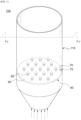
- FIG. 1 is a schematic view for describing the internal structure of a fluidized bed reactor according to exemplary embodiments of the present invention.
- a fluidized bed reactor 100 may include a reactor body 110 and a dispersion plate 40.
- each of the first injection columns 60 may include a column body 62, a cap part 64 and a first injection port 66 penetrating the first column body 62.
- the first injection columns 60 may have a bubble cap or a tubyere structure.
- the fluidized bed reactor 100 may include a plurality of second injection columns 70.
- the plurality of second injection columns may be disposed spaced apart from each other along the circumference of the dispersion plate 40.
- the gas reception part 73 may be in contact with the upper surface of the base plate 50.
- the gas passage 104 may penetrate the base plate 50 to be connected to the gas reception part 73, thereby supplying the gas.
- the gas reception part 73 may be in contact with the inner surface of the reactor body 110.
- the gas passage 104 may penetrate the reactor body 110 to be connected to the gas reception part 73, thereby supplying the gas.
- FIGS. 8 and 9 are schematic views for describing a formation direction ED of the second injection port according to some embodiments.
- the second injection port 75 may be formed parallel to the tangential direction TD of the dispersion plate 40.
- the second injection port 75 may be formed to be inclined toward the inner surface of the reactor body 110.
- an inclination angle between the tangential direction TD and the second injection port 75 may be 0° to 30°, 0° to 20°, or 0° to 10°.
- a waste cathode active material mixture may be prepared from a waste cathode of a lithium secondary battery (e.g., process S10).
- the lithium secondary battery may include an electrode assembly including a cathode, an anode and a separation member interposed between the cathode and the anode.
- the cathode and the anode may include a cathode active material layer and an anode active material layer coated on a cathode current collector and an anode current collector, respectively.
- a cathode active material included in the cathode active material layer may include a lithium metal oxide containing lithium and a transition metal.
- the lithium metal oxide may be represented by Formula 1 below.
- Formula 1 Li x M1 a M2 6 M3 c O y
- M1, M2, and M3 may be selected from Ni, Co, Mn, Na, Mg, Ca, Ti, V, Cr, Cu, Zn, Ge, Sr, Ag, Ba, Zr, Nb, Mo, Al, Ga or B.
- x, y, a, b and c may satisfy 0 ⁇ x ⁇ 1.1, 2 ⁇ y ⁇ 2.02, 0 ⁇ a ⁇ 1, 0 ⁇ b ⁇ 1, 0 ⁇ c ⁇ 1, 0 ⁇ a+b+c ⁇ 1.
- the cathode active material may be an NCM-based lithium oxide including nickel, cobalt and manganese.
- the cathode may be separated from the waste lithium secondary battery to recover a waste cathode.
- the waste cathode includes the cathode current collector (e.g., aluminum (Al)) and the cathode active material layer as described above, and the cathode active material layer may include a conductive material and a binder together with the above-described cathode active material.
- the conductive material may include, for example, a carbon-based material such as graphite, carbon black, graphene, carbon nanotube or the like.
- the binder may include, for example, a resin material such as vinylidene fluoride-hexafluoropropylene copolymer (PVDF-co-HFP), polyvinylidene fluoride (PVDF), polyacrylonitrile, polymethyl methacrylate or the like.
- the recovered waste cathode may be pulverized to produce a waste cathode active material mixture.
- the waste cathode active material mixture may be manufactured in the form of powder.
- the waste cathode active material mixture includes powder of a lithium-transition metal oxide as described above, and may include, for example, the NCM-based lithium metal oxide powder.
- the term "waste cathode active material mixture” may refer to a raw material which is input into a fluidized bed reaction treatment to be described below after the cathode current collector is substantially removed from the waste cathode.
- the waste cathode active material mixture may include cathode active material particles such as the NCM-based lithium oxide.
- the waste cathode active material mixture may also include some components derived from the binder or the conductive material.
- the waste cathode active material mixture may be substantially composed of the cathode active material particles.
- the waste cathode active material mixture may have an average particle diameter (D50) of 5 to 100 ⁇ m.
- D50 average particle diameter
- the lithium-transition metal oxide such as Li(NCM)O 2 to be recovered may be easily separated from the cathode current collector, the conductive material and the binder included in the waste cathode active material mixture.
- the waste cathode active material mixture may be subjected to heat treatment before inputting it into the fluidized bed reactor to be described below.
- heat treatment impurities such as the conductive material and the binder included in the waste cathode active material mixture may be removed or reduced, such that the lithium-transition metal oxide may be introduced into the fluidized bed reactor with high purity.
- the heat treatment may be performed at a temperature of, for example, about 100°C to 500°C, or about 350°C to 450°C. Within the above range, while the impurities may be substantially removed, decomposition and damage of the lithium-transition metal oxide may be prevented.
- the waste cathode active material mixture may be reacted in the fluidized bed reactor 100 to form a preliminary precursor mixture 90.
- the fluidized bed reactor 100 may be divided into the reactor body 110, a reactor lower portion 120 and a reactor upper portion 130.
- the reactor body 110 may include a heating means such as a heater or may be integrally formed with the heating means.
- the dispersion plate 40 may be coupled to the lower portion of the reactor body 110.
- a bottom portion of the dispersion plate 40 in the reactor body 110 may be defined as the reactor lower portion 120.
- the waste cathode active material mixture may be supplied into the reactor body 110 through supply passages 106a and 106b.
- the waste cathode active material mixture may be dropped through a first supply passage 106a connected to the reactor upper portion 130, or may be input through a second supply passage 106b connected to the lower portion of the reactor body 110.
- the first and second supply passages 106a and 106b may also be used together to supply the waste cathode active material mixture.
- a reaction gas for converting the waste cathode active material mixture into a preliminary precursor may be supplied into the reactor body 110 through the reaction gas passage 102 connected to the reactor lower portion 120.
- the reaction gas includes a reducing gas, for example, hydrogen (H 2 ) may be supplied.
- the reaction gas may be injected into the reactor body 110 through the first injection columns 60. Since the reaction gas is supplied from the lower portion of the fluidized bed reactor 100 and contacts the waste cathode active material mixture, the waste cathode active material mixture may react with the reaction gas while moving to the reactor upper portion 130 to be converted into the preliminary precursor.
- the dead zone formed at the outer portion or the peripheral portion of the base plate 50 may be removed by the gas (e.g., the reaction gas and/or the carrier gas) injected through the second injection column 70.
- the gas e.g., the reaction gas and/or the carrier gas
- whirl may be formed by the gas, thereby inducing a uniform reaction between the waste cathode active material and the reaction gas.
- reaction gas passage 102 which supplies the reaction gas and/or the carrier gas to the first injection column 60 and the gas passage 104 which supplies the gas to the second injection column 70 may be distinguished from each other. Accordingly, since the gas flow according to the second injection column 70 may be artificially and variably adjusted, optimization of the gas flow rate for eliminating the dead zone may be easily achieved.
- the lithium-transition metal oxide may be reduced by the hydrogen gas to produce, for example, lithium hydroxide (LiOH), a preliminary lithium precursor including the lithium oxide (e.g., Li 2 O), and a transition metal or a transition metal oxide.
- LiOH lithium hydroxide
- a preliminary lithium precursor including the lithium oxide e.g., Li 2 O
- a transition metal or a transition metal oxide e.g., Ni, Co, NiO, CoO and MnO may be produced together with the preliminary lithium precursor by a reduction reaction.
- the reduction reaction in the reactor body 110 may be performed at about 400°C to 700°C, and preferably 450°C to 550°C. Within the above reaction temperature range, the reduction reaction may be facilitated without causing re-aggregation or recombination of the preliminary lithium precursor and the transition metal/transition metal oxide.
- a carrier gas may also be supplied together with the reaction gas from the reactor lower portion 120 through the reaction gas passage 102.
- the carrier gas may include an inert gas such as nitrogen (N 2 ), argon (Ar), etc.
- the carrier gas may also be supplied by injecting through the first injection columns 60 of the dispersion plate to facilitate the formation of fluidized bed. For example, the formation of whirl through the carrier gas may be facilitated.
- the transition metal-containing particles 92 including nickel, cobalt or manganese are relatively heavier than the preliminary lithium precursor particles 94, such that the preliminary lithium precursor particles 94 may be first collected through outlets 160a and 160b.
- the preliminary precursor mixture 90 including the preliminary lithium precursor particles 94 and the transition metal-containing particles 92 may be collected through a second outlet 160b connected to the reactor body 110.
- the preliminary precursor mixture 90 may be directly recovered in a fluidized bed forming region, thereby increasing the yield.
- lithium carbonate e.g., Li 2 CO 3
- a carbon-containing gas such as carbon monoxide (CO), or carbon dioxide (CO 2 ), etc.
- a crystallized lithium precursor may be obtained through a reaction with the carbon-containing gas.
- lithium carbonate may be collected by injecting the carbon-containing gas together during the water washing treatment.
Landscapes
- Chemical & Material Sciences (AREA)
- Engineering & Computer Science (AREA)
- Organic Chemistry (AREA)
- Chemical Kinetics & Catalysis (AREA)
- Combustion & Propulsion (AREA)
- Materials Engineering (AREA)
- Inorganic Chemistry (AREA)
- Manufacturing & Machinery (AREA)
- Electrochemistry (AREA)
- General Chemical & Material Sciences (AREA)
- Secondary Cells (AREA)
- Manufacture And Refinement Of Metals (AREA)
Abstract
Description
- The present invention relates to a fluidized bed reactor and a method for recovering an active metal from a lithium secondary battery using the same, and more specifically, to a fluidized bed reactor which includes a dispersion plate and a method for recovering an active metal from a lithium secondary battery using the fluidized bed reactor.
- Recently, a secondary battery has been developed and widely applied to portable electronic telecommunication devices such as a camcorder, a mobile phone, a laptop computer, etc., and vehicles such as a hybrid vehicle and an electric electric vehicle as a power source thereof. As the secondary battery, a lithium secondary battery has a high operating voltage and a high energy density per unit weight, and is advantageous in terms of a charging speed and light weight, such that development and application thereof have been proceeded in this regard.
- A lithium metal oxide may be used as a cathode active material of the lithium secondary battery. The lithium metal oxide may contain transition metals such as nickel, cobalt or manganese.
- As the above-described expensive valuable metals are used for the cathode active material, 20% or more of manufacturing costs of the lithium secondary battery is required to manufacture the cathode material. In addition, as the environmental protection issues are recently emerging, research on a method for recycling the cathode active material is being conducted.
- Conventionally, a wet method for sequentially recovering valuable metals by leaching a waste cathode active material in a strong acid such as sulfuric acid has been used, but the wet method is disadvantageous in terms of regeneration selectivity, regeneration time, etc., and may cause environmental pollution. Therefore, a method for recovering valuable metals by using a dry-based reaction through contact them with a reaction gas is being studied.
- However, as a size of the cathode active material particles supplied for the dry reaction becomes finer, unevenness of the reaction due to agglomeration may occur. In addition, a recovery rate of the active material may be decreased due to local uneven supply of a reaction gas within the reactor.
- For example, Korean Patent Registration No.
10-0843601 - An object of the present invention is to provide a fluidized bed reactor having improved reaction efficiency and reliability.
- Another object of the present invention is to provide a method for recovering an active metal of a lithium secondary battery using the fluidized bed reactor.
- To achieve the above objects, according to an aspect of the present invention, there is provided a fluidized bed reactor including: a reactor body; a dispersion plate which is coupled to a lower portion of the reactor body, and includes a base plate and first injection columns protruding from an upper surface of the base plate; and a second injection column which is adjacent to a circumference of the dispersion plate, and is configured to inject a gas so as to form a gas flow which rotates along an inner surface of the reactor body.
- In one embodiment, the gas flow formed by the second injection column may rotate in unidirection.
- In one embodiment, a plurality of the second injection columns may be disposed spaced apart along the circumference of the dispersion plate.
- In one embodiment, if a length of the circumference of the dispersion plate may be defined as L, and the number of the second injection columns is defined as n, the second injection columns may be disposed spaced apart from each other at an interval of L/(n+1) to L/(n-1).
- In one embodiment, the fluidized bed reactor may further include a gas passage configured to supply the gas to the second injection column.
- In one embodiment, the second injection column may further include: a gas reception part configured to receive the gas from the gas passage, and a second injection port configured to inject the gas so that the gas is circulated in a direction parallel to the upper surface of the base plate at an inside of the reactor body.
- In one embodiment, the gas reception part may be in contact with the upper surface of the base plate.
- In one embodiment, the gas reception part may be in contact with the inner surface of the reactor body.
- In one embodiment, the second injection port may be parallel to a tangential direction of the dispersion plate.
- In one embodiment, the second injection port may be inclined toward the inner surface of the reactor body.
- In one embodiment, the first injection column may further include a column body which extends from the upper surface of the base plate, a cap part which covers an upper portion of the column body, and a first injection port which penetrates the column body.
- In one embodiment, the first injection port may be inclined toward the upper surface of the base plate.
- In one embodiment, the first injection columns may be arranged at a predetermined pitch or in a predetermined grid shape.
- In one embodiment, the reactor body may further include a reaction gas passage configured to supply a reaction gas from a bottom portion of the base plate.
- According to another aspect of the present invention, there is provided a method for recovering an active metal of a lithium secondary battery, including: preparing a waste cathode active material mixture obtained from a waste cathode of the lithium secondary battery; reacting the waste cathode active material mixture in the above-described fluidized bed reactor to form a preliminary precursor mixture; and selectively recovering a lithium precursor from the preliminary precursor mixture.
- The fluidized bed reactor according to exemplary embodiments of the present invention may prevent an occurrence of a dead zone where the reaction gas does not reach in the dispersion plate. Accordingly, uniform reaction region and fluidized bed may be formed.
- The fluidized bed reactor according to exemplary embodiments may be used in a recycling process through hydrogen reduction of the cathode active material of the lithium secondary battery. The fluidized bed reactor may form the uniform reaction region and fluidized bed, thereby increasing a recovery efficiency of the cathode active material.
-
-
FIG. 1 is a schematic view for describing the internal structure of a fluidized bed reactor according to exemplary embodiments of the present invention. -
FIG. 2 is a schematic plan view illustrating a dispersion plate according to exemplary embodiments. -
FIG. 3 is a schematic cross-sectional view of the dispersion plate ofFIG. 2 taken on line II-II' in the arrow direction. -
FIG. 4 is a schematic perspective view illustrating a second injection column according to exemplary embodiments. -
FIG. 5 is a plan view illustrating the internal structure of the fluidized bed reactor by taking the fluidized bed reactor ofFIG. 1 on line I-I' in the arrow direction. -
FIGS. 6 and7 are schematic views for describing the arrangement structure of the second injection column according to some exemplary embodiments. -
FIGS. 8 and9 are schematic views for describing the formation direction of a second injection port according to some exemplary embodiments. -
FIG. 10 is a schematic view for describing a method for recovering an active metal of a lithium secondary battery using a fluidized bed reactor according to exemplary embodiments. - According to exemplary embodiments of the present invention, a fluidized bed reactor capable of forming uniform reaction region and fluidized bed may be provided.
- In addition, according to exemplary embodiments of the present invention, a dry-based method for recovering an active metal from a lithium secondary battery with high purity and high yield using the fluidized bed reactor may be provided.
- Hereinafter, exemplary embodiments of the present invention will be described in detail with reference to the accompanying drawings. However, these embodiments are merely an example, and the present invention is not limited to the specific embodiments described as the example.
- As used herein, the term "precursor" is used to comprehensively refer to a compound including specific metals to provide the specific metals included in the electrode active material.
-
FIG. 1 is a schematic view for describing the internal structure of a fluidized bed reactor according to exemplary embodiments of the present invention. - Referring to
FIG. 1 , a fluidizedbed reactor 100 may include areactor body 110 and adispersion plate 40. - The
reactor body 110 may extend from a lower end to an upper end of the fluidizedbed reactor 100, and may include a hollow portion formed inside thereactor body 110. The hollow portion may be partitioned by thedispersion plate 40. -
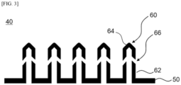
FIG. 2 is a schematic plan view illustrating the dispersion plate according to exemplary embodiments. In addition,FIG. 3 is a schematic cross-sectional view of the dispersion plate ofFIG. 2 taken on line II-II' in the arrow direction. - Referring to
FIGS. 2 and3 , thedispersion plate 40 may include abase plate 50 and a plurality offirst injection columns 60 protruding from thebase plate 50. - For example, the
base plate 50 may be a circular or polygonal plate made of a metal or ceramic material. - The
first injection columns 60 may have a shape protruding upwardly from an upper surface of thebase plate 50. Thefirst injection columns 60 may be regularly arranged on the upper surface of thebase plate 50 in a predetermined arrangement form (e.g., predetermined grid arrangement) with an array pitch for uniform diffusion and distribution of the reaction gas. - For example, the
injection columns FIG. 2 , thefirst injection columns 60 may be arranged according to an equilateral triangular pitch. - Referring to
FIG. 3 , each of thefirst injection columns 60 may include acolumn body 62, acap part 64 and afirst injection port 66 penetrating thefirst column body 62. For example, thefirst injection columns 60 may have a bubble cap or a tubyere structure. - For example, as shown in
FIG. 3 , thefirst injection port 66 may be formed to be inclined from an upper portion of theinjection column 60 toward thebase plate 50. For example, thefirst injection port 66 may have a shape extending from the upper portion of theinjection column 60 toward thebase plate 50. - In one embodiment, an inclination angle between a vertical direction from the upper surface of the
base plate 50 and thefirst injection ports 66 may be about 30° to 60°. - As the
first injection ports 66 are formed to be inclined with respect to the upper surface of thebase plate 50, the reaction gas may be injected so as to spread toward thebase plate 50. Accordingly, a formation of a fluidized layer may be facilitated while a reactive material (e.g., precursor particles or active material particles) settling on the upper surface of thebase plate 50 rises. - As described above, when the
first injection columns 60 are arranged on thebase plate 50 according to a predetermined pitch (e.g., a triangular arrangement), a region where theinjection columns 60 are not arranged at a predetermined interval may occur in a peripheral portion or outer portion of thebase plate 50. Accordingly, as indicated by the dotted oval inFIG. 2 , a dead zone (D) where the reaction gas does not reach may occur. - In this case, the reaction gas may not reach an inner surface of the
reactor body 110, such that the fluidized bed may not be uniformly formed. In addition, reactive material particles which are aggregated on the inner surface of thereactor body 110 may stick thereto, thereby reducing a reaction yield. - However, as shown in
FIG. 1 , thefluidized bed reactor 100 according to exemplary embodiments of the present invention may include asecond injection column 70 disposed adjacent to a circumference of thedispersion plate 40, thereby suppressing a formation of the dead zone D. -
FIG. 4 is a schematic perspective view illustrating the second injection column according to exemplary embodiments. - Referring to
FIG. 4 , thesecond injection column 70 may include, for example, agas reception part 73 configured to receive a gas supplied from agas passage 104 to be described below, and asecond injection port 75 configured to inject the gas so that the gas is circulated in a direction parallel to the upper surface of the base plate at an inside of thereactor body 110. - In one embodiment, the gas may include a carrier gas and/or a reaction gas to be described below.
-
FIG. 5 is a plan view illustrating the internal structure of the fluidized bed reactor taken on line I-I' ofFIG. 1 and observed in the arrow direction. In addition,FIGS. 6 and7 are schematic views for describing the arrangement structure of the second injection column according to some exemplary embodiments. - As shown in
FIG. 5 , the gas injected from thesecond injection column 70 may form a gas flow which rotates along the inner surface of thereactor body 110. Accordingly, the formation of the dead zone D may be suppressed. - In one embodiment, the gas injected from the
second injection column 70 may form a gas flow which rotates in unidirection. Accordingly, a whirl in unidirection may be induced, thereby more uniformly dispersing the reactive material (e.g., precursor particles or active material particles). - As shown in
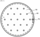
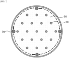
FIGS. 6 and7 , thefluidized bed reactor 100 may include a plurality ofsecond injection columns 70. The plurality of second injection columns may be disposed spaced apart from each other along the circumference of thedispersion plate 40. - For example, if a length of the circumference of the
dispersion plate 40 is defined as L, and the number of the second injection columns is defined as n, the second injection columns may be disposed spaced apart from each other at an interval of L/(n+1) to L/(n-1). - For example, as shown in
FIG. 6 , two second injection columns may be disposed along the circumference of thedispersion plate 40 at an interval of L/2. Alternatively, as shown inFIG. 7 , four second injection columns may be disposed along the circumference of thedispersion plate 40 at an interval of L/4. In this case, the whirl may be better formed. - In one embodiment, the
gas reception part 73 may be in contact with the upper surface of thebase plate 50. Thegas passage 104 may penetrate thebase plate 50 to be connected to thegas reception part 73, thereby supplying the gas. - In one embodiment, the
gas reception part 73 may be in contact with the inner surface of thereactor body 110. Thegas passage 104 may penetrate thereactor body 110 to be connected to thegas reception part 73, thereby supplying the gas. -
FIGS. 8 and9 are schematic views for describing a formation direction ED of the second injection port according to some embodiments. - In one embodiment, as shown in
FIG. 8 , thesecond injection port 75 may be formed parallel to the tangential direction TD of thedispersion plate 40. - In one embodiment, as shown in
FIG. 9 , thesecond injection port 75 may be formed to be inclined toward the inner surface of thereactor body 110. - In some embodiments, an inclination angle between the tangential direction TD and the
second injection port 75 may be 0° to 30°, 0° to 20°, or 0° to 10°. -
FIG. 10 is a schematic view for describing a method for recovering an active metal from a lithium secondary battery using thefluidized bed reactor 100 according to exemplary embodiments. - Hereinafter, the method for recovering an active metal from a lithium secondary battery and the configuration/structure of the above-described
fluidized bed reactor 100 will be described together with reference toFIG. 10 . - Referring to
FIG. 10 , a waste cathode active material mixture may be prepared from a waste cathode of a lithium secondary battery (e.g., process S10). - The lithium secondary battery may include an electrode assembly including a cathode, an anode and a separation member interposed between the cathode and the anode. The cathode and the anode may include a cathode active material layer and an anode active material layer coated on a cathode current collector and an anode current collector, respectively.
- For example, a cathode active material included in the cathode active material layer may include a lithium metal oxide containing lithium and a transition metal.
- In some embodiments, the lithium metal oxide may be represented by Formula 1 below.
[Formula 1] LixM1aM26M3cOy
- In Formula 1, M1, M2, and M3 may be selected from Ni, Co, Mn, Na, Mg, Ca, Ti, V, Cr, Cu, Zn, Ge, Sr, Ag, Ba, Zr, Nb, Mo, Al, Ga or B. In the Formula 1, x, y, a, b and c may satisfy 0<x≤1.1, 2≤y≤2.02, 0<a<1, 0<b<1, 0<c<1, 0<a+b+c≤1.
- In some embodiments, the cathode active material may be an NCM-based lithium oxide including nickel, cobalt and manganese.
- The cathode may be separated from the waste lithium secondary battery to recover a waste cathode. The waste cathode includes the cathode current collector (e.g., aluminum (Al)) and the cathode active material layer as described above, and the cathode active material layer may include a conductive material and a binder together with the above-described cathode active material.
- The conductive material may include, for example, a carbon-based material such as graphite, carbon black, graphene, carbon nanotube or the like. The binder may include, for example, a resin material such as vinylidene fluoride-hexafluoropropylene copolymer (PVDF-co-HFP), polyvinylidene fluoride (PVDF), polyacrylonitrile, polymethyl methacrylate or the like.
- According to exemplary embodiments, the recovered waste cathode may be pulverized to produce a waste cathode active material mixture. Accordingly, the waste cathode active material mixture may be manufactured in the form of powder. The waste cathode active material mixture includes powder of a lithium-transition metal oxide as described above, and may include, for example, the NCM-based lithium metal oxide powder.
- As used herein, the term "waste cathode active material mixture" may refer to a raw material which is input into a fluidized bed reaction treatment to be described below after the cathode current collector is substantially removed from the waste cathode. In one embodiment, the waste cathode active material mixture may include cathode active material particles such as the NCM-based lithium oxide. In one embodiment, the waste cathode active material mixture may also include some components derived from the binder or the conductive material. In one embodiment, the waste cathode active material mixture may be substantially composed of the cathode active material particles.
- In some embodiments, the waste cathode active material mixture may have an average particle diameter (D50) of 5 to 100 µm. Within the above range, the lithium-transition metal oxide such as Li(NCM)O2 to be recovered may be easily separated from the cathode current collector, the conductive material and the binder included in the waste cathode active material mixture.
- In some embodiments, the waste cathode active material mixture may be subjected to heat treatment before inputting it into the fluidized bed reactor to be described below. By the heat treatment, impurities such as the conductive material and the binder included in the waste cathode active material mixture may be removed or reduced, such that the lithium-transition metal oxide may be introduced into the fluidized bed reactor with high purity.
- The heat treatment may be performed at a temperature of, for example, about 100°C to 500°C, or about 350°C to 450°C. Within the above range, while the impurities may be substantially removed, decomposition and damage of the lithium-transition metal oxide may be prevented.
- For example, in process S20, the waste cathode active material mixture may be reacted in the
fluidized bed reactor 100 to form apreliminary precursor mixture 90. - As shown in
FIG. 10 , thefluidized bed reactor 100 may be divided into thereactor body 110, a reactorlower portion 120 and a reactorupper portion 130. - The
reactor body 110 may include a heating means such as a heater or may be integrally formed with the heating means. - The
dispersion plate 40 may be coupled to the lower portion of thereactor body 110. A bottom portion of thedispersion plate 40 in thereactor body 110 may be defined as the reactorlower portion 120. - The waste cathode active material mixture may be supplied into the
reactor body 110 throughsupply passages first supply passage 106a connected to the reactorupper portion 130, or may be input through asecond supply passage 106b connected to the lower portion of thereactor body 110. In one embodiment, the first andsecond supply passages - A reaction gas for converting the waste cathode active material mixture into a preliminary precursor may be supplied into the
reactor body 110 through thereaction gas passage 102 connected to the reactorlower portion 120. According to exemplary embodiments, the reaction gas includes a reducing gas, for example, hydrogen (H2) may be supplied. - The reaction gas may be injected into the
reactor body 110 through thefirst injection columns 60. Since the reaction gas is supplied from the lower portion of thefluidized bed reactor 100 and contacts the waste cathode active material mixture, the waste cathode active material mixture may react with the reaction gas while moving to the reactorupper portion 130 to be converted into the preliminary precursor. - The dead zone formed at the outer portion or the peripheral portion of the
base plate 50 may be removed by the gas (e.g., the reaction gas and/or the carrier gas) injected through thesecond injection column 70. In addition, whirl may be formed by the gas, thereby inducing a uniform reaction between the waste cathode active material and the reaction gas. - In one embodiment, the
reaction gas passage 102 which supplies the reaction gas and/or the carrier gas to thefirst injection column 60 and thegas passage 104 which supplies the gas to thesecond injection column 70 may be distinguished from each other. Accordingly, since the gas flow according to thesecond injection column 70 may be artificially and variably adjusted, optimization of the gas flow rate for eliminating the dead zone may be easily achieved. - In some embodiments, the lithium-transition metal oxide may be reduced by the hydrogen gas to produce, for example, lithium hydroxide (LiOH), a preliminary lithium precursor including the lithium oxide (e.g., Li2O), and a transition metal or a transition metal oxide. For example, Ni, Co, NiO, CoO and MnO may be produced together with the preliminary lithium precursor by a reduction reaction.
- The reduction reaction in the
reactor body 110 may be performed at about 400°C to 700°C, and preferably 450°C to 550°C. Within the above reaction temperature range, the reduction reaction may be facilitated without causing re-aggregation or recombination of the preliminary lithium precursor and the transition metal/transition metal oxide. - In some embodiments, a carrier gas may also be supplied together with the reaction gas from the reactor
lower portion 120 through thereaction gas passage 102. For example, the carrier gas may include an inert gas such as nitrogen (N2), argon (Ar), etc. The carrier gas may also be supplied by injecting through thefirst injection columns 60 of the dispersion plate to facilitate the formation of fluidized bed. For example, the formation of whirl through the carrier gas may be facilitated. - The
preliminary precursor mixture 90 including preliminarylithium precursor particles 94 and transition metal-containing particles 92 (e.g., the transition metal or transition metal oxide) may be formed within thereactor body 110. The preliminarylithium precursor particles 94 may include, for example, lithium hydroxide, lithium oxide and/or lithium carbonate (Li carbonate). - In one embodiment, the transition metal-containing
particles 92 including nickel, cobalt or manganese are relatively heavier than the preliminarylithium precursor particles 94, such that the preliminarylithium precursor particles 94 may be first collected throughoutlets - In one embodiment, the preliminary
lithium precursor particles 94 may be discharged through afirst outlet 160a connected to the reactorupper portion 130. In this case, selective recovery of the preliminarylithium precursor particles 94 according to the weight gradient may be facilitated. - In one embodiment, the
preliminary precursor mixture 90 including the preliminarylithium precursor particles 94 and the transition metal-containingparticles 92 may be collected through asecond outlet 160b connected to thereactor body 110. In this case, thepreliminary precursor mixture 90 may be directly recovered in a fluidized bed forming region, thereby increasing the yield. - In one embodiment, the
preliminary precursor mixture 90 may be collected together through the first andsecond outlets - The preliminary
lithium precursor particles 94 collected through theoutlets - In some embodiments, the preliminary
lithium precursor particles 94 may be washed with water. Through the water washing treatment, the preliminary lithium precursor particles in the form of lithium hydroxide (LiOH) may be substantially dissolved in water and separated from the transition metal precursor to be recovered first. A lithium precursor substantially composed of lithium hydroxide may be obtained through a crystallization process, etc. of the lithium hydroxide dissolved in water. - In one embodiment, the preliminary lithium precursor particles in the form of lithium oxide and lithium carbonate may be substantially removed through the water washing treatment. In one embodiment, the preliminary lithium precursor particles in the form of lithium oxide and lithium carbonate may be at least partially converted into lithium hydroxide through the water washing treatment.
- In some embodiments, lithium carbonate (e.g., Li2CO3) may be obtained as a lithium precursor by reacting the preliminary
lithium precursor particles 94 with a carbon-containing gas such as carbon monoxide (CO), or carbon dioxide (CO2), etc. A crystallized lithium precursor may be obtained through a reaction with the carbon-containing gas. For example, lithium carbonate may be collected by injecting the carbon-containing gas together during the water washing treatment. - In some embodiments, a transition metal precursor may be obtained from the collected transition metal-containing particles 92 (e.g., process S40).
- For example, after collecting the preliminary
lithium precursor particles 94 through theoutlets particles 92 may be recovered. Thereafter, the transition metal-containingparticles 92 may be treated with an acid solution to form precursors in the form of acid salts of each transition metal. - In one embodiment, sulfuric acid may be used as the acid solution. In this case, NiSO4, MnSO4 and CoSO4 may be recovered as the transition metal precursor, respectively.
- As described above, the lithium precursor is collected through a dry process, and then the transition metal precursors are selectively extracted using the acid solution, such that purity and selectivity of the respective metal precursors may be improved, and a load of the wet process may be decreased, thereby reducing an increase in wastewater and byproducts.
Claims (15)
- A fluidized bed reactor comprising:a reactor body;a dispersion plate which is coupled to a lower portion of the reactor body, and comprises a base plate and first injection columns protruding from an upper surface of the base plate; anda second injection column which is adjacent to a circumference of the dispersion plate, and is configured to inject a gas so as to form a gas flow which rotates along an inner surface of the reactor body.
- The fluidized bed reactor according to claim 1, wherein the gas flow formed by the second injection column rotates in unidirection.
- The fluidized bed reactor according to claim 1 or 2, wherein a plurality of the second injection columns are disposed spaced apart along the circumference of the dispersion plate.
- The fluidized bed reactor according to claim 3, wherein if a length of the circumference of the dispersion plate is defined as L, and the number of the second injection columns is defined as n,
the second injection columns are disposed spaced apart from each other at an interval of L/(n+1) to L/(n-1). - The fluidized bed reactor according to one of claims 1 to 4, further comprising a gas passage configured to supply the gas to the second injection column.
- The fluidized bed reactor according to claim 5, wherein the second injection column comprises:a gas reception part configured to receive the gas from the gas passage, anda second injection port configured to inject the gas so that the gas is circulated in a direction parallel to the upper surface of the base plate at an inside of the reactor.
- The fluidized bed reactor according to claim 6, wherein the gas reception part is in contact with the upper surface of the base plate.
- The fluidized bed reactor according to claim 6, wherein the gas reception part is in contact with the inner surface of the reactor body.
- The fluidized bed reactor according to claim 8, wherein the second injection port is parallel to a tangential direction of the dispersion plate.
- The fluidized bed reactor according to claim 8, wherein the second injection port is inclined toward the inner surface of the reactor body.
- The fluidized bed reactor according to one of claims 1 to 10, wherein the first injection column comprises a column body which extends from the upper surface of the base plate, a cap part which covers an upper portion of the column body, and a first injection port which penetrates the column body.
- The fluidized bed reactor according to claim 11, wherein the first injection port is inclined toward the upper surface of the base plate.
- The fluidized bed reactor according to one of claims 1 to 12, wherein the first injection columns are arranged at a predetermined pitch or in a predetermined grid shape.
- The fluidized bed reactor according to one of claims 1 to 13, wherein the reactor body further comprises a reaction gas passage configured to supply a reaction gas from a bottom portion of the base plate.
- A method for recovering an active metal of a lithium secondary battery, comprising:preparing a waste cathode active material mixture obtained from a waste cathode of the lithium secondary battery;reacting the waste cathode active material mixture in the fluidized bed reactor of one of claims 1 to 14 to form a preliminary precursor mixture; andselectively recovering a lithium precursor from the preliminary precursor mixture.
Applications Claiming Priority (2)
| Application Number | Priority Date | Filing Date | Title |
|---|---|---|---|
| KR1020220105530A KR20240027384A (en) | 2022-08-23 | 2022-08-23 | Fludized bed reactor and method of recycling active metal of lithium secondary battery utilizing the same |
| PCT/KR2023/012114 WO2024043603A1 (en) | 2022-08-23 | 2023-08-16 | Fluidized bed reactor and method for recovering active metal of lithium secondary battery using same |
Publications (2)
| Publication Number | Publication Date |
|---|---|
| EP4578541A1 true EP4578541A1 (en) | 2025-07-02 |
| EP4578541A4 EP4578541A4 (en) | 2025-12-17 |
Family
ID=90013579
Family Applications (1)
| Application Number | Title | Priority Date | Filing Date |
|---|---|---|---|
| EP23857637.5A Pending EP4578541A4 (en) | 2022-08-23 | 2023-08-16 | Fluidized bed reactor and method for recovering active metal from a lithium secondary battery. |
Country Status (5)
| Country | Link |
|---|---|
| EP (1) | EP4578541A4 (en) |
| JP (1) | JP2025527004A (en) |
| KR (1) | KR20240027384A (en) |
| CN (1) | CN119768230A (en) |
| WO (1) | WO2024043603A1 (en) |
Family Cites Families (7)
| Publication number | Priority date | Publication date | Assignee | Title |
|---|---|---|---|---|
| JP2722969B2 (en) * | 1992-10-26 | 1998-03-09 | 住友化学工業株式会社 | Gas dispersion plate for fluidized bed reactor |
| EP1577003A1 (en) * | 2004-03-15 | 2005-09-21 | Borealis Technology Oy | Method and apparatus for producing polymers |
| KR100843601B1 (en) | 2005-12-28 | 2008-07-03 | 주식회사 엘지화학 | Fluidized bed reactor |
| KR101134001B1 (en) * | 2008-12-31 | 2012-04-05 | 제일모직주식회사 | Tuyere-type Distributor for Fluidized Bed Reactor for Minimizing Dead Zone |
| KR102772279B1 (en) * | 2019-06-27 | 2025-02-25 | 주식회사 엘지화학 | Fluidized bed dryer with dead zone reduction structure |
| KR102851288B1 (en) * | 2019-12-27 | 2025-08-28 | 에스케이이노베이션 주식회사 | Fludized bed reactor and method of recycling active metal of lithium secondary battery utilizing the same |
| KR20210144137A (en) * | 2020-05-21 | 2021-11-30 | 주식회사 엘지화학 | Dispersing plate with holes placed along concentric circles |
-
2022
- 2022-08-23 KR KR1020220105530A patent/KR20240027384A/en active Pending
-
2023
- 2023-08-16 JP JP2025511780A patent/JP2025527004A/en active Pending
- 2023-08-16 EP EP23857637.5A patent/EP4578541A4/en active Pending
- 2023-08-16 CN CN202380061826.6A patent/CN119768230A/en active Pending
- 2023-08-16 WO PCT/KR2023/012114 patent/WO2024043603A1/en not_active Ceased
Also Published As
| Publication number | Publication date |
|---|---|
| CN119768230A (en) | 2025-04-04 |
| WO2024043603A1 (en) | 2024-02-29 |
| JP2025527004A (en) | 2025-08-15 |
| EP4578541A4 (en) | 2025-12-17 |
| KR20240027384A (en) | 2024-03-04 |
Similar Documents
| Publication | Publication Date | Title |
|---|---|---|
| KR102020238B1 (en) | Method of recycling active metal of lithium secondary battery | |
| CN114845802B (en) | Fluidized bed reactor and method for recovering active metals of lithium secondary battery using the same | |
| EP3862322A1 (en) | Method for regenerating lithium precursor and system for regenerating lithium precursor | |
| JP7575468B2 (en) | Method for recovering active metals from lithium secondary batteries | |
| US20220407133A1 (en) | Fluidized bed reactor and method for recovering active metal of lithium secondary battery using same | |
| JP7676433B2 (en) | Method for recovering active metals from lithium secondary batteries | |
| KR102753512B1 (en) | Fluidized bed reactor and method of recycling active metal of lithium secondary battery utilizing the same | |
| EP4578541A1 (en) | Fluidized bed reactor and method for recovering active metal of lithium secondary battery using same | |
| EP4579873A1 (en) | Fluidized bed reactor and method for recovering active metal of lithium secondary battery by using same | |
| CN114901387B (en) | Fluidized bed reactor and method for recovering active metals from lithium secondary batteries using the same | |
| JP7707179B2 (en) | Method for recovering active metals from lithium secondary batteries | |
| EP4148151A1 (en) | Method for recovering active metals from lithium secondary battery | |
| US20230420762A1 (en) | Fluidized bed reactor and method for recycling lithium precursor using same |
Legal Events
| Date | Code | Title | Description |
|---|---|---|---|
| STAA | Information on the status of an ep patent application or granted ep patent |
Free format text: STATUS: THE INTERNATIONAL PUBLICATION HAS BEEN MADE |
|
| PUAI | Public reference made under article 153(3) epc to a published international application that has entered the european phase |
Free format text: ORIGINAL CODE: 0009012 |
|
| STAA | Information on the status of an ep patent application or granted ep patent |
Free format text: STATUS: REQUEST FOR EXAMINATION WAS MADE |
|
| 17P | Request for examination filed |
Effective date: 20250319 |
|
| AK | Designated contracting states |
Kind code of ref document: A1 Designated state(s): AL AT BE BG CH CY CZ DE DK EE ES FI FR GB GR HR HU IE IS IT LI LT LU LV MC ME MK MT NL NO PL PT RO RS SE SI SK SM TR |
|
| DAV | Request for validation of the european patent (deleted) | ||
| DAX | Request for extension of the european patent (deleted) | ||
| A4 | Supplementary search report drawn up and despatched |
Effective date: 20251118 |
|
| RIC1 | Information provided on ipc code assigned before grant |
Ipc: B01J 8/44 20060101AFI20251112BHEP Ipc: B01J 8/18 20060101ALI20251112BHEP Ipc: C01D 15/02 20060101ALI20251112BHEP Ipc: C01D 15/08 20060101ALI20251112BHEP Ipc: H01M 10/54 20060101ALI20251112BHEP |