EP4578478A2 - Agent administering medical device - Google Patents
Agent administering medical device Download PDFInfo
- Publication number
- EP4578478A2 EP4578478A2 EP25170734.5A EP25170734A EP4578478A2 EP 4578478 A2 EP4578478 A2 EP 4578478A2 EP 25170734 A EP25170734 A EP 25170734A EP 4578478 A2 EP4578478 A2 EP 4578478A2
- Authority
- EP
- European Patent Office
- Prior art keywords
- agent
- barrier
- enclosure
- tube
- opening
- Prior art date
- Legal status (The legal status is an assumption and is not a legal conclusion. Google has not performed a legal analysis and makes no representation as to the accuracy of the status listed.)
- Pending
Links
Images



Classifications
-
- A—HUMAN NECESSITIES
- A61—MEDICAL OR VETERINARY SCIENCE; HYGIENE
- A61M—DEVICES FOR INTRODUCING MEDIA INTO, OR ONTO, THE BODY; DEVICES FOR TRANSDUCING BODY MEDIA OR FOR TAKING MEDIA FROM THE BODY; DEVICES FOR PRODUCING OR ENDING SLEEP OR STUPOR
- A61M5/00—Devices for bringing media into the body in a subcutaneous, intra-vascular or intramuscular way; Accessories therefor, e.g. filling or cleaning devices, arm-rests
- A61M5/14—Infusion devices, e.g. infusing by gravity; Blood infusion; Accessories therefor
- A61M5/142—Pressure infusion, e.g. using pumps
- A61M5/145—Pressure infusion, e.g. using pumps using pressurised reservoirs, e.g. pressurised by means of pistons
- A61M5/155—Pressure infusion, e.g. using pumps using pressurised reservoirs, e.g. pressurised by means of pistons pressurised by gas introduced into the reservoir
-
- A—HUMAN NECESSITIES
- A61—MEDICAL OR VETERINARY SCIENCE; HYGIENE
- A61B—DIAGNOSIS; SURGERY; IDENTIFICATION
- A61B17/00—Surgical instruments, devices or methods
- A61B17/00491—Surgical glue applicators
-
- A—HUMAN NECESSITIES
- A61—MEDICAL OR VETERINARY SCIENCE; HYGIENE
- A61M—DEVICES FOR INTRODUCING MEDIA INTO, OR ONTO, THE BODY; DEVICES FOR TRANSDUCING BODY MEDIA OR FOR TAKING MEDIA FROM THE BODY; DEVICES FOR PRODUCING OR ENDING SLEEP OR STUPOR
- A61M31/00—Devices for introducing or retaining media, e.g. remedies, in cavities of the body
-
- A—HUMAN NECESSITIES
- A61—MEDICAL OR VETERINARY SCIENCE; HYGIENE
- A61B—DIAGNOSIS; SURGERY; IDENTIFICATION
- A61B17/00—Surgical instruments, devices or methods
- A61B17/00234—Surgical instruments, devices or methods for minimally invasive surgery
-
- A—HUMAN NECESSITIES
- A61—MEDICAL OR VETERINARY SCIENCE; HYGIENE
- A61M—DEVICES FOR INTRODUCING MEDIA INTO, OR ONTO, THE BODY; DEVICES FOR TRANSDUCING BODY MEDIA OR FOR TAKING MEDIA FROM THE BODY; DEVICES FOR PRODUCING OR ENDING SLEEP OR STUPOR
- A61M11/00—Sprayers or atomisers specially adapted for therapeutic purposes
- A61M11/006—Sprayers or atomisers specially adapted for therapeutic purposes operated by applying mechanical pressure to the liquid to be sprayed or atomised
- A61M11/007—Syringe-type or piston-type sprayers or atomisers
-
- A—HUMAN NECESSITIES
- A61—MEDICAL OR VETERINARY SCIENCE; HYGIENE
- A61M—DEVICES FOR INTRODUCING MEDIA INTO, OR ONTO, THE BODY; DEVICES FOR TRANSDUCING BODY MEDIA OR FOR TAKING MEDIA FROM THE BODY; DEVICES FOR PRODUCING OR ENDING SLEEP OR STUPOR
- A61M11/00—Sprayers or atomisers specially adapted for therapeutic purposes
- A61M11/02—Sprayers or atomisers specially adapted for therapeutic purposes operated by air or other gas pressure applied to the liquid or other product to be sprayed or atomised
-
- A—HUMAN NECESSITIES
- A61—MEDICAL OR VETERINARY SCIENCE; HYGIENE
- A61M—DEVICES FOR INTRODUCING MEDIA INTO, OR ONTO, THE BODY; DEVICES FOR TRANSDUCING BODY MEDIA OR FOR TAKING MEDIA FROM THE BODY; DEVICES FOR PRODUCING OR ENDING SLEEP OR STUPOR
- A61M11/00—Sprayers or atomisers specially adapted for therapeutic purposes
- A61M11/06—Sprayers or atomisers specially adapted for therapeutic purposes of the injector type
-
- A—HUMAN NECESSITIES
- A61—MEDICAL OR VETERINARY SCIENCE; HYGIENE
- A61M—DEVICES FOR INTRODUCING MEDIA INTO, OR ONTO, THE BODY; DEVICES FOR TRANSDUCING BODY MEDIA OR FOR TAKING MEDIA FROM THE BODY; DEVICES FOR PRODUCING OR ENDING SLEEP OR STUPOR
- A61M13/00—Insufflators for therapeutic or disinfectant purposes, i.e. devices for blowing a gas, powder or vapour into the body
-
- A—HUMAN NECESSITIES
- A61—MEDICAL OR VETERINARY SCIENCE; HYGIENE
- A61M—DEVICES FOR INTRODUCING MEDIA INTO, OR ONTO, THE BODY; DEVICES FOR TRANSDUCING BODY MEDIA OR FOR TAKING MEDIA FROM THE BODY; DEVICES FOR PRODUCING OR ENDING SLEEP OR STUPOR
- A61M5/00—Devices for bringing media into the body in a subcutaneous, intra-vascular or intramuscular way; Accessories therefor, e.g. filling or cleaning devices, arm-rests
- A61M5/14—Infusion devices, e.g. infusing by gravity; Blood infusion; Accessories therefor
- A61M5/142—Pressure infusion, e.g. using pumps
- A61M5/145—Pressure infusion, e.g. using pumps using pressurised reservoirs, e.g. pressurised by means of pistons
- A61M5/1452—Pressure infusion, e.g. using pumps using pressurised reservoirs, e.g. pressurised by means of pistons pressurised by means of pistons
- A61M5/1454—Pressure infusion, e.g. using pumps using pressurised reservoirs, e.g. pressurised by means of pistons pressurised by means of pistons spring-actuated, e.g. by a clockwork
-
- A—HUMAN NECESSITIES
- A61—MEDICAL OR VETERINARY SCIENCE; HYGIENE
- A61M—DEVICES FOR INTRODUCING MEDIA INTO, OR ONTO, THE BODY; DEVICES FOR TRANSDUCING BODY MEDIA OR FOR TAKING MEDIA FROM THE BODY; DEVICES FOR PRODUCING OR ENDING SLEEP OR STUPOR
- A61M5/00—Devices for bringing media into the body in a subcutaneous, intra-vascular or intramuscular way; Accessories therefor, e.g. filling or cleaning devices, arm-rests
- A61M5/178—Syringes
- A61M5/31—Details
- A61M5/315—Pistons; Piston-rods; Guiding, blocking or restricting the movement of the rod or piston; Appliances on the rod for facilitating dosing ; Dosing mechanisms
- A61M5/31565—Administration mechanisms, i.e. constructional features, modes of administering a dose
- A61M5/31576—Constructional features or modes of drive mechanisms for piston rods
- A61M5/31583—Constructional features or modes of drive mechanisms for piston rods based on rotational translation, i.e. movement of piston rod is caused by relative rotation between the user activated actuator and the piston rod
- A61M5/31586—Constructional features or modes of drive mechanisms for piston rods based on rotational translation, i.e. movement of piston rod is caused by relative rotation between the user activated actuator and the piston rod performed by rotationally moving or pivoted actuator, e.g. an injection lever or handle
-
- A—HUMAN NECESSITIES
- A61—MEDICAL OR VETERINARY SCIENCE; HYGIENE
- A61B—DIAGNOSIS; SURGERY; IDENTIFICATION
- A61B17/00—Surgical instruments, devices or methods
- A61B17/00234—Surgical instruments, devices or methods for minimally invasive surgery
- A61B2017/00292—Surgical instruments, devices or methods for minimally invasive surgery mounted on or guided by flexible, e.g. catheter-like, means
- A61B2017/00296—Surgical instruments, devices or methods for minimally invasive surgery mounted on or guided by flexible, e.g. catheter-like, means mounted on an endoscope
-
- A—HUMAN NECESSITIES
- A61—MEDICAL OR VETERINARY SCIENCE; HYGIENE
- A61B—DIAGNOSIS; SURGERY; IDENTIFICATION
- A61B17/00—Surgical instruments, devices or methods
- A61B17/00234—Surgical instruments, devices or methods for minimally invasive surgery
- A61B2017/00292—Surgical instruments, devices or methods for minimally invasive surgery mounted on or guided by flexible, e.g. catheter-like, means
- A61B2017/003—Steerable
-
- A—HUMAN NECESSITIES
- A61—MEDICAL OR VETERINARY SCIENCE; HYGIENE
- A61B—DIAGNOSIS; SURGERY; IDENTIFICATION
- A61B17/00—Surgical instruments, devices or methods
- A61B17/00234—Surgical instruments, devices or methods for minimally invasive surgery
- A61B2017/00292—Surgical instruments, devices or methods for minimally invasive surgery mounted on or guided by flexible, e.g. catheter-like, means
- A61B2017/0034—Surgical instruments, devices or methods for minimally invasive surgery mounted on or guided by flexible, e.g. catheter-like, means adapted to be inserted through a working channel of an endoscope
-
- A—HUMAN NECESSITIES
- A61—MEDICAL OR VETERINARY SCIENCE; HYGIENE
- A61B—DIAGNOSIS; SURGERY; IDENTIFICATION
- A61B17/00—Surgical instruments, devices or methods
- A61B17/00491—Surgical glue applicators
- A61B2017/00522—Sprayers
-
- A—HUMAN NECESSITIES
- A61—MEDICAL OR VETERINARY SCIENCE; HYGIENE
- A61B—DIAGNOSIS; SURGERY; IDENTIFICATION
- A61B17/00—Surgical instruments, devices or methods
- A61B2017/00743—Type of operation; Specification of treatment sites
- A61B2017/00818—Treatment of the gastro-intestinal system
-
- A—HUMAN NECESSITIES
- A61—MEDICAL OR VETERINARY SCIENCE; HYGIENE
- A61M—DEVICES FOR INTRODUCING MEDIA INTO, OR ONTO, THE BODY; DEVICES FOR TRANSDUCING BODY MEDIA OR FOR TAKING MEDIA FROM THE BODY; DEVICES FOR PRODUCING OR ENDING SLEEP OR STUPOR
- A61M2202/00—Special media to be introduced, removed or treated
- A61M2202/02—Gases
- A61M2202/0225—Carbon oxides, e.g. Carbon dioxide
-
- A—HUMAN NECESSITIES
- A61—MEDICAL OR VETERINARY SCIENCE; HYGIENE
- A61M—DEVICES FOR INTRODUCING MEDIA INTO, OR ONTO, THE BODY; DEVICES FOR TRANSDUCING BODY MEDIA OR FOR TAKING MEDIA FROM THE BODY; DEVICES FOR PRODUCING OR ENDING SLEEP OR STUPOR
- A61M2202/00—Special media to be introduced, removed or treated
- A61M2202/06—Solids
- A61M2202/064—Powder
-
- A—HUMAN NECESSITIES
- A61—MEDICAL OR VETERINARY SCIENCE; HYGIENE
- A61M—DEVICES FOR INTRODUCING MEDIA INTO, OR ONTO, THE BODY; DEVICES FOR TRANSDUCING BODY MEDIA OR FOR TAKING MEDIA FROM THE BODY; DEVICES FOR PRODUCING OR ENDING SLEEP OR STUPOR
- A61M2205/00—General characteristics of the apparatus
- A61M2205/04—General characteristics of the apparatus implanted
-
- A—HUMAN NECESSITIES
- A61—MEDICAL OR VETERINARY SCIENCE; HYGIENE
- A61M—DEVICES FOR INTRODUCING MEDIA INTO, OR ONTO, THE BODY; DEVICES FOR TRANSDUCING BODY MEDIA OR FOR TAKING MEDIA FROM THE BODY; DEVICES FOR PRODUCING OR ENDING SLEEP OR STUPOR
- A61M2205/00—General characteristics of the apparatus
- A61M2205/10—General characteristics of the apparatus with powered movement mechanisms
- A61M2205/103—General characteristics of the apparatus with powered movement mechanisms rotating
-
- A—HUMAN NECESSITIES
- A61—MEDICAL OR VETERINARY SCIENCE; HYGIENE
- A61M—DEVICES FOR INTRODUCING MEDIA INTO, OR ONTO, THE BODY; DEVICES FOR TRANSDUCING BODY MEDIA OR FOR TAKING MEDIA FROM THE BODY; DEVICES FOR PRODUCING OR ENDING SLEEP OR STUPOR
- A61M2205/00—General characteristics of the apparatus
- A61M2205/33—Controlling, regulating or measuring
- A61M2205/3331—Pressure; Flow
-
- A—HUMAN NECESSITIES
- A61—MEDICAL OR VETERINARY SCIENCE; HYGIENE
- A61M—DEVICES FOR INTRODUCING MEDIA INTO, OR ONTO, THE BODY; DEVICES FOR TRANSDUCING BODY MEDIA OR FOR TAKING MEDIA FROM THE BODY; DEVICES FOR PRODUCING OR ENDING SLEEP OR STUPOR
- A61M2210/00—Anatomical parts of the body
- A61M2210/06—Head
- A61M2210/0625—Mouth
-
- A—HUMAN NECESSITIES
- A61—MEDICAL OR VETERINARY SCIENCE; HYGIENE
- A61M—DEVICES FOR INTRODUCING MEDIA INTO, OR ONTO, THE BODY; DEVICES FOR TRANSDUCING BODY MEDIA OR FOR TAKING MEDIA FROM THE BODY; DEVICES FOR PRODUCING OR ENDING SLEEP OR STUPOR
- A61M2210/00—Anatomical parts of the body
- A61M2210/10—Trunk
- A61M2210/1042—Alimentary tract
- A61M2210/105—Oesophagus
-
- A—HUMAN NECESSITIES
- A61—MEDICAL OR VETERINARY SCIENCE; HYGIENE
- A61M—DEVICES FOR INTRODUCING MEDIA INTO, OR ONTO, THE BODY; DEVICES FOR TRANSDUCING BODY MEDIA OR FOR TAKING MEDIA FROM THE BODY; DEVICES FOR PRODUCING OR ENDING SLEEP OR STUPOR
- A61M2210/00—Anatomical parts of the body
- A61M2210/10—Trunk
- A61M2210/1042—Alimentary tract
- A61M2210/1053—Stomach
-
- A—HUMAN NECESSITIES
- A61—MEDICAL OR VETERINARY SCIENCE; HYGIENE
- A61M—DEVICES FOR INTRODUCING MEDIA INTO, OR ONTO, THE BODY; DEVICES FOR TRANSDUCING BODY MEDIA OR FOR TAKING MEDIA FROM THE BODY; DEVICES FOR PRODUCING OR ENDING SLEEP OR STUPOR
- A61M2210/00—Anatomical parts of the body
- A61M2210/10—Trunk
- A61M2210/1042—Alimentary tract
- A61M2210/1067—Anus
Definitions
- the present disclosure relates generally to a medical device that administers an agent. More particularly, at least some embodiments of the present disclosure relate to a medical device including a system that can be actuated to administer a dosage of an agent to a lumen.
- an endoscopic medical procedure may require hemostasis of bleeding tissue within the gastrointestinal tract, for example in the esophagus, stomach, or intestines.
- a user inserts a sheath of an endoscope into a body lumen of a patient.
- the user utilizes a handle of the endoscope to control the endoscope during the procedure.
- Tools are passed through a working channel of the endoscope via, for example, a port in the handle, to deliver treatment at the procedure site near a distal end of the endoscope.
- the procedure site is remote from the operator.
- a hemostatic agent may be delivered by a device inserted into the working channel of the endoscope.
- Agent delivery may be achieved through mechanical systems, for example. Such systems, however, may require numerous steps or actuations to achieve delivery, may not achieve a desired rate of agent delivery or a desired dosage of agent, may result in the agent clogging portions of the delivery device, may result in inconsistent dosing of agent, or may not result in the agent reaching the treatment site deep within the GI tract.
- the current disclosure may solve one or more of these issues or other issues in the art.
- a medical device may comprise an enclosure defining a cavity for containing agent, a lumen for receiving a pressurized gas, and a barrier positioned between the cavity and the lumen, the barrier including at least one opening for storing agent, wherein rotation of the barrier relative to the lumen establishes fluid communication between the at least one opening and the lumen for delivering agent from the at least one opening to the lumen.
- a bottom end of the cavity may include a wall adjacent to the barrier, wherein the wall includes a wall opening, wherein the wall opening is located on an area of the wall so that the wall opening is aligned with the at least one opening via rotation of the barrier. Alignment of the wall opening with the at least one opening may permit agent from the enclosure to enter the at least one opening.
- the enclosure may be rotatable relative to the barrier and/or the lumen.
- the barrier may be rotatable relative to the enclosure.
- the agent may remain in the at least one opening until fluid communication between the at least one opening and the lumen is established.
- the enclosure may feed the at least one opening with agent via gravity.
- the at least one opening for storing agent may feed the lumen with agent via gravity when fluid communication between the at least one opening and the lumen is established.
- the at least one opening for storing agent may be a plurality of openings arranged radially about the barrier.
- the plurality of openings may be symmetrically arranged.
- Each of the plurality of openings may be different in size.
- the medical device may further comprise an intermediary barrier, wherein the intermediary barrier is positioned between the barrier and the lumen, and wherein the intermediary barrier includes an intermediary opening positioned to be aligned with one of the plurality of openings via rotation of the barrier.
- the intermediary barrier may be rotatable relative to the barrier.
- the lumen may be a flexible catheter capable of traversing a tortuous body lumen, and further comprising a source of the pressurized gas.
- a medical device may comprise a cartridge including a plurality of chambers, wherein each of the chambers stores a pre-filled amount of agent, a lumen for receiving a pressurized gas, a channel establishing fluid communication between a first end of the cartridge and the lumen for delivering agent from the cartridge to the lumen, and a plunger coupled to a second end of the cartridge so that the plunger is aligned with one chamber of the plurality of chambers, wherein the plunger advances longitudinally into the one chamber, thereby pushing the pre-filled amount of agent towards the channel, and wherein the cartridge is rotatable relative to the plunger to align the plunger with another of the plurality of chambers.
- a method of administering an agent via a medical device may comprise positioning the medical device, including an enclosure, a barrier, and a lumen, so that a distal end of the lumen is adjacent to a targeted site, wherein the barrier is positioned between the enclosure and the lumen, the enclosure containing agent, and the barrier including at least one opening for storing the agent, providing a pressurized gas to the lumen, and rotating the barrier relative to the lumen so that fluid communication is established between the at least one opening and the lumen to deliver the agent from the at least one opening to the lumen.
- the method may further comprise rotating the barrier relative to the lumen so that the at least one opening and the lumen are not in fluid communication after a dose of the agent is delivered from the at least one opening to the lumen.
- distal refers to a portion farthest away from a user when introducing a device into a subject (e.g., patient).
- proximal refers to a portion closest to the user when placing the device into the subject.
- the present disclosure may solve one or more of the limitations in the art.
- the scope of the disclosure is defined by the attached claims and not the ability to solve a specific problem.
- the present disclosure is drawn to medical devices configured to administer doses of agents, e.g., therapeutic agents, among other aspects.
- the agent may be in any suitable form, including a powder form, which may be delivered to a stream of propellant/pressurized gas, e.g., CO 2 , nitrogen, air, etc.
- Said medical devices allow for the administration of agents in metered doses, which allows for a greater consistency in the quantity of the agent that reaches a target site.
- Medical system 5 includes a flexible shaft 50 (e.g., a catheter) and a handle 52 connected at a proximal end of flexible shaft 50.
- Handle 52 or some other device for actuating or controlling medical system 5 and any tool or devices associated with medical system 5, includes first and second actuating devices 42, 43, which control articulation of flexible shaft 50, and/or an articulation joint at a distal end of flexible shaft 50, in multiple directions.
- Devices 42, 43 may be, for example, rotatable knobs that rotate about their axes to push/pull actuating elements (not shown).
- actuating elements such as cables or wires suitable for medical procedures (e.g., medical grade plastic or metal), extend distally from a proximal end of medical system 5 and connect to flexible shaft 50 to control movement thereof.
- actuating elements may be operated independently of handle 52.
- Distal ends of actuating elements may extend through flexible shaft 50 and terminate at an actuating joint and/or a distal tip of flexible shaft 50.
- one or more actuating elements may be connected to an articulation joint, and actuation of actuating elements may control the actuating joint or the distal end of flexible shaft 50 to move in multiple directions.
- one or more electrical cables may extend from the proximal end of endoscope 5 to the distal end of flexible shaft 50 and may provide electrical controls to imaging, lighting, and/or other electrical devices at the distal end of flexible shaft 50, and may carry imaging signals from the distal end of flexible shaft 50 proximally to be processed and/or displayed on a display.
- Handle 52 may also include ports 54, 46 for introducing and/or removing tools, fluids, or other materials from the patient. Port 54 may be used to introduce tools. Port 46 may be connected to an umbilicus for introducing fluid, suction, and/or wiring for electronic components. For example, as shown in FIG. 1A , port 54 receives a tube 100, which extends from the proximal end to the distal end of flexible shaft 50, via a working channel 50a of shaft 50.
- tube 100 of medical device 1 is attached to a pressurized gas source 56, e.g., CO 2 , which may be controlled by a user to turn on/off and to adjust a rate at which gas flows into tube 100.
- a pressurized gas source 56 e.g., CO 2
- Source 56 may be a gas canister or tank, a source of gas supplied by a medical facility, or any other suitable source.
- Medical device 1 further includes an enclosure 10, and a barrier 11 positioned between enclosure 10 and tube 100. Enclosure 10 and barrier 11 are coupled to a proximal portion of tube 100, distal of the connection between tube 100 and source 56.
- FIGS. 1B and 1C illustrate an embodiment of medical device 1, 1' in FIG. 1A in further detail.
- medical device 1 includes enclosure 10 defining a cavity for containing an agent 1000, a tube (e.g., a catheter or a sheath) 100 defining a lumen 100a receiving pressurized gas, e.g., CO 2 , from a proximal end, and barrier 11 positioned between the cavity of enclosure 10 and lumen 100a.
- the shape or size of enclosure 10 is not particularly limited, and may be any suitable shape or size, including cylindrical.
- barrier 11 is rotatable relative to tube 100 and lumen 100a, e.g., about a central axis of barrier 11.
- a user may deliver a distal end of tube 100 of medical device 1 into the body of a subject, e.g., via a natural orifice (such as a mouth or anus) and through a tortuous natural body lumen of the subject, such as an esophagus, stomach, colon, etc.
- Tube 100 may be delivered in any suitable way, for example, through working channel 50a of endoscope 5, by inserting a distal end of tube 100 into port 54 of endoscope 5.
- a user may direct/position the distal end of tube 100 to an intended target site for administration of agent 1000.
- barrier 21 may be rotatable relative to both tube 100 and enclosure 10'.
- enclosure 10' may be rotatable relative to barrier 21 and/or tube 100. Rotation of barrier 21 and enclosure 10' may also be actuated by any suitable action.
- Trigger 18 includes a lever 18a coupled to a linkage 18c via an articulating joint 18b, and linkage 18c coupled to a plunger 18e via another articulating joint 18d.
- a distal portion of plunger 18e is housed within a proximal portion of cartridge 31, and is coupled to cartridge 31 in any suitable manner so that the distal end of plunger 18e faces one of chambers 32a-32f with which plunger 18e is aligned.
- a spring 19 coils around a distal portion of plunger 18e outside of cartridge 31 up until a stop 17 fixated on plunger 18e, thereby spring-biasing plunger 18e in its aforementioned position of facing one of chambers 32a-32f.
- Spring 19 is not particularly limited and may be any suitable spring.
- stop 17 may be of any suitable material, such as rubber.
- Plunger 18e advances within cartridge 31 and one of chambers 32a-32f up until spring 19 is fully compressed, thereby inhibiting any further advancement of plunger 18e towards cartridge 31. Once lever 18 is released, spring-biased plunger 18e automatically reverts back to its initial position of being outside of and facing one of chambers 32a-32f.
Landscapes
- Health & Medical Sciences (AREA)
- Life Sciences & Earth Sciences (AREA)
- Engineering & Computer Science (AREA)
- Animal Behavior & Ethology (AREA)
- General Health & Medical Sciences (AREA)
- Heart & Thoracic Surgery (AREA)
- Veterinary Medicine (AREA)
- Biomedical Technology (AREA)
- Public Health (AREA)
- Anesthesiology (AREA)
- Hematology (AREA)
- Surgery (AREA)
- Vascular Medicine (AREA)
- Nuclear Medicine, Radiotherapy & Molecular Imaging (AREA)
- Medical Informatics (AREA)
- Molecular Biology (AREA)
- Mechanical Engineering (AREA)
- Infusion, Injection, And Reservoir Apparatuses (AREA)
- Endoscopes (AREA)
Abstract
Description
- This application claims the benefit of priority from
U.S. Provisional Application No. 62/942,988, filed on December 3, 2019 - The present disclosure relates generally to a medical device that administers an agent. More particularly, at least some embodiments of the present disclosure relate to a medical device including a system that can be actuated to administer a dosage of an agent to a lumen.
- In certain medical procedures, it may be necessary to stop or minimize bleeding internal to the body. For example, an endoscopic medical procedure may require hemostasis of bleeding tissue within the gastrointestinal tract, for example in the esophagus, stomach, or intestines.
- During an endoscopic procedure, a user inserts a sheath of an endoscope into a body lumen of a patient. The user utilizes a handle of the endoscope to control the endoscope during the procedure. Tools are passed through a working channel of the endoscope via, for example, a port in the handle, to deliver treatment at the procedure site near a distal end of the endoscope. The procedure site is remote from the operator.
- To achieve hemostasis at the remote site, a hemostatic agent may be delivered by a device inserted into the working channel of the endoscope. Agent delivery may be achieved through mechanical systems, for example. Such systems, however, may require numerous steps or actuations to achieve delivery, may not achieve a desired rate of agent delivery or a desired dosage of agent, may result in the agent clogging portions of the delivery device, may result in inconsistent dosing of agent, or may not result in the agent reaching the treatment site deep within the GI tract. The current disclosure may solve one or more of these issues or other issues in the art.
- According to an example, a medical device may comprise an enclosure defining a cavity for containing agent, a lumen for receiving a pressurized gas, and a barrier positioned between the cavity and the lumen, the barrier including at least one opening for storing agent, wherein rotation of the barrier relative to the lumen establishes fluid communication between the at least one opening and the lumen for delivering agent from the at least one opening to the lumen. A bottom end of the cavity may include a wall adjacent to the barrier, wherein the wall includes a wall opening, wherein the wall opening is located on an area of the wall so that the wall opening is aligned with the at least one opening via rotation of the barrier. Alignment of the wall opening with the at least one opening may permit agent from the enclosure to enter the at least one opening. The enclosure may be rotatable relative to the barrier and/or the lumen. The barrier may be rotatable relative to the enclosure. The agent may remain in the at least one opening until fluid communication between the at least one opening and the lumen is established. The enclosure may feed the at least one opening with agent via gravity. The at least one opening for storing agent may feed the lumen with agent via gravity when fluid communication between the at least one opening and the lumen is established.
- In another example, the at least one opening for storing agent may be a plurality of openings arranged radially about the barrier. The plurality of openings may be symmetrically arranged. Each of the plurality of openings may be different in size. When fluid communication is established between one opening of the plurality of openings and the lumen, the other openings of the plurality of openings and the lumen are not in fluid communication.
- In another example, the medical device may further comprise an intermediary barrier, wherein the intermediary barrier is positioned between the barrier and the lumen, and wherein the intermediary barrier includes an intermediary opening positioned to be aligned with one of the plurality of openings via rotation of the barrier. The intermediary barrier may be rotatable relative to the barrier. The lumen may be a flexible catheter capable of traversing a tortuous body lumen, and further comprising a source of the pressurized gas.
- According to an example, a medical device may comprise a cartridge including a plurality of chambers, wherein each of the chambers stores a pre-filled amount of agent, a lumen for receiving a pressurized gas, a channel establishing fluid communication between a first end of the cartridge and the lumen for delivering agent from the cartridge to the lumen, and a plunger coupled to a second end of the cartridge so that the plunger is aligned with one chamber of the plurality of chambers, wherein the plunger advances longitudinally into the one chamber, thereby pushing the pre-filled amount of agent towards the channel, and wherein the cartridge is rotatable relative to the plunger to align the plunger with another of the plurality of chambers. The plunger may be coupled to the cartridge so that the plunger is spring-biased to a position outside of the one chamber and aligned with the one chamber. The medical device may further comprise a trigger including a lever coupled to a linkage via a first articulating joint and a linkage coupled to a plunger via a second articulating joint.
- According to an example, a method of administering an agent via a medical device may comprise positioning the medical device, including an enclosure, a barrier, and a lumen, so that a distal end of the lumen is adjacent to a targeted site, wherein the barrier is positioned between the enclosure and the lumen, the enclosure containing agent, and the barrier including at least one opening for storing the agent, providing a pressurized gas to the lumen, and rotating the barrier relative to the lumen so that fluid communication is established between the at least one opening and the lumen to deliver the agent from the at least one opening to the lumen. The method may further comprise rotating the barrier relative to the lumen so that the at least one opening and the lumen are not in fluid communication after a dose of the agent is delivered from the at least one opening to the lumen.
- The accompanying drawings, which are incorporated in and constitute a part of this specification, illustrate various exemplary embodiments and together with the description, serve to explain the principles of the disclosed embodiments.
-
FIG. 1A is a side view of a portion of a shaft of an endoscope including a medical device, according to an embodiment. -
FIGS. 1B-C are cross-sectional views of the medical device ofFIG. 1A . -
FIG. 2A is a cross-sectional view of a medical device, according to another embodiment. -
FIG. 2B is a top view of the barrier ofFIG. 2A . -
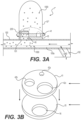
FIG. 3A is a cross-sectional view of a medical device, according to another embodiment. -
FIG. 3B is a top perspective view of the barrier ofFIG. 3A over the intermediary barrier ofFIG. 3A . -
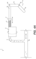
FIG. 4A is a side view of a medical device, according to another embodiment. -
FIG. 4B is a top view of the cartridge ofFIG. 4A . - Reference will now be made in detail to aspects of the present disclosure, examples of which are illustrated in the accompanying drawings. Wherever possible, the same or similar reference numbers will be used through the drawings to refer to the same or like parts. The term "distal" refers to a portion farthest away from a user when introducing a device into a subject (e.g., patient). By contrast, the term "proximal" refers to a portion closest to the user when placing the device into the subject.
- Both the foregoing general description and the following detailed description are exemplary and explanatory only and are not restrictive of the features, as claimed. As used herein, the terms "comprises," "comprising," "having," "including," or other variations thereof, are intended to cover a non-exclusive inclusion such that a process, method, article, or apparatus that comprises a list of elements does not include only those elements, but may include other elements not expressly listed or inherent to such a process, method, article, or apparatus. In this disclosure, relative terms, such as, for example, "about," "substantially," "generally," and "approximately" are used to indicate a possible variation of ±10% in a stated value or characteristic.
- The present disclosure may solve one or more of the limitations in the art. The scope of the disclosure, however, is defined by the attached claims and not the ability to solve a specific problem. The present disclosure is drawn to medical devices configured to administer doses of agents, e.g., therapeutic agents, among other aspects. The agent may be in any suitable form, including a powder form, which may be delivered to a stream of propellant/pressurized gas, e.g., CO2, nitrogen, air, etc. Said medical devices allow for the administration of agents in metered doses, which allows for a greater consistency in the quantity of the agent that reaches a target site.
- Referring to
FIG. 1A , a medical system 5, e.g., an endoscope, according to an embodiment is shown. Medical system 5 includes a flexible shaft 50 (e.g., a catheter) and ahandle 52 connected at a proximal end offlexible shaft 50.Handle 52, or some other device for actuating or controlling medical system 5 and any tool or devices associated with medical system 5, includes first andsecond actuating devices 42, 43, which control articulation offlexible shaft 50, and/or an articulation joint at a distal end offlexible shaft 50, in multiple directions.Devices 42, 43, may be, for example, rotatable knobs that rotate about their axes to push/pull actuating elements (not shown). The actuating elements, such as cables or wires suitable for medical procedures (e.g., medical grade plastic or metal), extend distally from a proximal end of medical system 5 and connect toflexible shaft 50 to control movement thereof. Alternatively, or additionally, a user may operate actuating elements independently ofhandle 52. Distal ends of actuating elements may extend throughflexible shaft 50 and terminate at an actuating joint and/or a distal tip offlexible shaft 50. For example, one or more actuating elements may be connected to an articulation joint, and actuation of actuating elements may control the actuating joint or the distal end offlexible shaft 50 to move in multiple directions. - In addition, one or more electrical cables (not shown) may extend from the proximal end of endoscope 5 to the distal end of
flexible shaft 50 and may provide electrical controls to imaging, lighting, and/or other electrical devices at the distal end offlexible shaft 50, and may carry imaging signals from the distal end offlexible shaft 50 proximally to be processed and/or displayed on a display.Handle 52 may also includeports Port 54 may be used to introduce tools.Port 46 may be connected to an umbilicus for introducing fluid, suction, and/or wiring for electronic components. For example, as shown inFIG. 1A ,port 54 receives atube 100, which extends from the proximal end to the distal end offlexible shaft 50, via a workingchannel 50a ofshaft 50. - As shown in
FIG. 1A ,tube 100 ofmedical device 1 is attached to apressurized gas source 56, e.g., CO2, which may be controlled by a user to turn on/off and to adjust a rate at which gas flows intotube 100.Source 56 may be a gas canister or tank, a source of gas supplied by a medical facility, or any other suitable source.Medical device 1 further includes anenclosure 10, and abarrier 11 positioned betweenenclosure 10 andtube 100.Enclosure 10 andbarrier 11 are coupled to a proximal portion oftube 100, distal of the connection betweentube 100 andsource 56. -
FIGS. 1B and 1C illustrate an embodiment ofmedical device 1, 1' inFIG. 1A in further detail. As discussed above,medical device 1 includesenclosure 10 defining a cavity for containing anagent 1000, a tube (e.g., a catheter or a sheath) 100 defining alumen 100a receiving pressurized gas, e.g., CO2, from a proximal end, andbarrier 11 positioned between the cavity ofenclosure 10 andlumen 100a. The shape or size ofenclosure 10 is not particularly limited, and may be any suitable shape or size, including cylindrical. As indicated by the directional arrows inFIG. 1B ,barrier 11 is rotatable relative totube 100 andlumen 100a, e.g., about a central axis ofbarrier 11. In other embodiments,barrier 11 may be rotatable relative to bothtube 100 andenclosure 10. In some other embodiments,enclosure 10 may be rotatable relative tobarrier 11 and/ortube 100. Rotation ofbarrier 11 may be by any suitable action, for example, by hand or by mechanical, electrical, or pneumatic action. -
Barrier 11 may be an annular, disk-like structure with openings and a passage therethrough. For example,barrier 11 includes afirst opening 12a on the barrier surface (e.g., an upper surface) adjacent to the cavity ofenclosure 10, for receivingagent 1000 in apassage 14 that extends throughbarrier 11.Barrier 11 further includes asecond opening 12b on the opposite barrier surface (e.g., a bottom surface) adjacent totube 100 andlumen 100a, from whichagent 1000 may be dispensed intolumen 100a. It is noted that the size and shape offirst opening 12a andsecond opening 12b are not particularly limited, and may be any suitable size or shape.First opening 12a andsecond opening 12b are located on opposite ends ofbarrier 11, but are connected viapassage 14 extending across the length and thickness ofbarrier 11.Tube 100 also includes anopening 101 which may or may not be aligned withsecond opening 12b ofbarrier 11, depending on the rotational position ofbarrier 11 relative totube 100 andlumen 100a. Thus, the rotation ofbarrier 11 relative totube 100 may establish fluid communication betweenopening 12b andlumen 100a for deliveringagent 1000 frompassage 14 tolumen 100a.Enclosure 10 feeds opening 12a withagent 1000 via gravity, andpassage 14storing agent 1000 feedslumen 100a withagent 1000 via gravity whensecond opening 12b andlumen opening 101 are aligned. In other embodiments,agent 1000 may be delivered toopening 12a and/orlumen 100a via other suitable mechanisms.Barrier 11 may also be rotated so thatsecond opening 12b andopening 101 oflumen 100a are not aligned, thereby inhibiting the delivery ofagent 1000 frompassage 14 tolumen 100a. In this instance,passage 14 receives and stores agent 10000, until fluid communication betweenopening 12b ofpassage 14 andlumen 100a is established. It is noted thatenclosure 10, in any rotational position ofbarrier 11, is not in fluid communication withlumen 100a. Furthermore, in embodiments prior to any use,passage 14 may be empty an withoutagent 1000. - In some embodiments, a bottom end of the cavity of
enclosure 10 may include awall 105 adjacent tobarrier 11.Wall 105 may include anopening 105a that may or may not be aligned with opening 12a ofbarrier 11, depending on the rotational position ofbarrier 11 relative toenclosure 10. Thus, in such embodiments,barrier 11 and/orenclosure 10 may be rotated to alignopening 105a with opening 12a ofbarrier 11 to deliveragent 1000 fromenclosure 10 topassage 14 throughopening 12a. This is illustrated inFIG. 1B , in whichopening 105a ofwall 105 andopening 12a ofbarrier 11 are aligned, thereby feedingpassage 14 withagent 1000 fromenclosure 10.FIG. 1C showsbarrier 11 rotated by approximately 180° from its position inFIG. 1B relative toenclosure 10, and as a result, opening 105a ofwall 105 andopening 12a are not aligned, being on opposite ends from one another. It is understood that thebarrier 11 may be rotatable to any degree for alignment withopening 12a. Thus, opening 12a is sealed bywall 105, andagent 1000 is no longer fed intoopening 12a. It is noted thatopening 105a aligns withopening 12a whensecond opening 12b does not align with opening 101 oftube 100, andopening 105a does not align withopening 12a whensecond opening 12b aligns with opening 101 oftube 100. Thus,passage 14 may receiveagent 1000, prior toagent 1000 being fed tolumen 100a. This allows formedical device 1 to administer a metered dose, i.e., the amount ofagent 1000 stored inpassage 14, per each degree of rotation, e.g., 180°, ofbarrier 11 and/orenclosure 10. Furthermore, in some other embodiments, bothwall 105 andtube 100 may respectively include a plurality of openings. It is noted thatpassage 14 is capable of connecting openings ofwall 105 and oftube 100 that are 180° apart. However, this is not desired, and in such embodiments, none of the openings ofwall 105 are 180° apart from any of the openings oftube 100. As a result, there cannot be fluid communication betweenpassage 14 and said openings ofwall 105 andtube 100, at the same time. Instead, fluid communication betweenpassage 14 and the openings ofwall 105 andtube 100 is staggered, but not simultaneous. Such embodiments would allow for continuous rotation (both clockwise and counterclockwise) ofbarrier 11 relative toenclosure 10 to result inpassage 14receiving agent 1000 after a degree of rotation and subsequently dispensingagent 1000 after a further degree of rotation ofbarrier 11. - Referring to
FIGS. 1A-1C , an example of howmedical device 1 may be used is further discussed below. A user may deliver a distal end oftube 100 ofmedical device 1 into the body of a subject, e.g., via a natural orifice (such as a mouth or anus) and through a tortuous natural body lumen of the subject, such as an esophagus, stomach, colon, etc.Tube 100 may be delivered in any suitable way, for example, through workingchannel 50a of endoscope 5, by inserting a distal end oftube 100 intoport 54 of endoscope 5. A user may direct/position the distal end oftube 100 to an intended target site for administration ofagent 1000. A user may then fillenclosure 10 withagent 1000, if not filled already, and rotatebarrier 11 and/orenclosure 10 relative totube 100 andlumen 100a so that opening 105a aligns withopening 12a, thereby feedingpassage 14 withagent 1000. As discussed above, when opening 105a aligns withopening 12a,second opening 12b does not align with opening 101 oftube 100. Thus,agent 1000 is received and stored bypassage 14. A user may then rotatebarrier 11 to align opening 12b with opening 101 oftube 100, so that all ofagent 1000 stored inpassage 14 is fed frompassage 14 tolumen 100a, thereby administering a metered dose ofagent 1000. A user may turn on the pressurized gas source at any time prior to the alignment ofopening 12b withopening 101 and supply pressurized gas until the metered dose ofagent 1000 reaches the target tissue site. Alternatively, a user may start supply of pressurized gas after the supply ofagent 1000 tolumen 100a. - In
FIG. 2A , another embodiment of medical device 1' is shown. Like the embodiment discussed above, medical device 1' includes an enclosure 10' defining a cavity for containing anagent 1000, a tube (e.g., a catheter or a sheath) 100 defining alumen 100a receiving pressurized gas, e.g., CO2, from a proximal end, and abarrier 21 positioned between the cavity ofenclosure 10 andlumen 100a. The shape or size of enclosure 10' is also not particularly limited, and may be any suitable shape or size. As indicated by the directional arrows inFIG. 2A ,barrier 21 is also rotatable relative totube 100 andlumen 100a. In other embodiments,barrier 21 may be rotatable relative to bothtube 100 and enclosure 10'. In some other embodiments, enclosure 10' may be rotatable relative tobarrier 21 and/ortube 100. Rotation ofbarrier 21 and enclosure 10' may also be actuated by any suitable action. -
Barrier 21, as shown in bothFIGS. 2A and 2B , includes a plurality of openings, i.e., sixopenings 22a-22f, of equal or approximately equal size, i.e., width or diameter, symmetrically arranged radially about a central axis of rotation ofbarrier 21. It is noted that the number of openings, the size of openings, the shape of openings, and the arrangement of openings onbarrier 21 is not particularly limited, and may be any suitable configuration. For example, in other embodiments,barrier 21 may have four circular openings, each of which has varying diameters from one another. Each ofopenings 22a-22f extends through the thickness ofbarrier 21, and is configured to receive and store a pre-determined or selected amount ofagent 1000, depending on the size of the openings. Thus,agent 1000 fromenclosure 10 feeds intoopenings 22a-22f, via gravity in some embodiments, until said openings are filled. Note thatFIG. 2A shows half ofbarrier 21 in perspective to show the position of openings 21a, 21b, 21c, and 21d. - By rotation of
barrier 21 relative totube 100 andlumen 100a, one ofopenings 22a-22f may align withopening 101, thereby establishing fluid communication between the one opening andlumen 100a for deliveringagent 1000 from the one opening to lumen 100a via gravity. In some embodiments, enclosure 10' may further include aseal 205, which is positioned adjacently abovebarrier 21, above where one ofopenings 22a-22f may be located, and directly above opening 101 oftube 100. Thus, as one opening ofopenings 22a-22f aligns with opening 101 via rotation ofbarrier 21, an excess amount ofagent 1000 above the one opening is shaved off byseal 205 and the one opening is sealed from receivingfurther agent 1000 from enclosure 10' when that opening aligns with opening 101 oftube 100. This allows for medical device 1' to administer a metered dose, i.e., the amount ofagent 1000 stored inopenings 22a-22f, per each degree of rotation, e.g., 60°, ofbarrier 21 and/or enclosure 10'. It is noted that as a result of such configuration, when fluid communication is established between one ofopenings 22a-22f andlumen 100a, no fluid communication is established between the other remaining openings andlumen 100a, as the bottom of the remaining openings is sealed bytube 100. - As shown in
FIG. 2B , which shows a top view ofbarrier 21,barrier 21 may also be rotated so that none ofopenings 22a-22f are aligned with opening 101 oftube 100, thereby inhibiting the delivery ofagent 1000 from any ofopenings 22a-22f to lumen 100a. In this instance, an amount ofagent 1000 is stored inopenings 22a-22f until fluid communication between the openings andlumen 100a is established. - Referring to
FIGS. 2A-2B , an example of how medical device 1' may be used is further discussed below. Similar tomedical device 1, medical device 1' may be delivered into the body of a subject, and directed to an intended target site foragent 1000 administration in the same manner. A user may then fill enclosure 10' withagent 1000, if not filled already, which will fillopenings 22a-22f withagent 1000. The user then may rotatebarrier 21 relative totube 100 andlumen 100a so that one ofopenings 22a-22f aligns withopening 101. Such alignment results inseal 205 shaving off an excess amount ofagent 1000 above the one opening, sealing the one opening from being fed any more ofagent 1000 from enclosure 10', andfeeding lumen 100a withagent 1000 stored in the one opening. As discussed above, when the one opening aligns with opening 101 oftube 100, the remainingopenings 22a-22f do not align with opening 101 oftube 100. Thus,agent 1000 is stored within the remainingopenings 22a-22f, until each of the remaining openings is aligned with opening 101 via rotation ofbarrier 21, in turn. A user may turn on the pressurized gas source at any time prior to or during the alignment of one of theopenings 22a-22f withopening 101, as in the embodiment described in connection withFIGS. 1B-1C . - In
FIG. 3A , another embodiment ofmedical device 1‴ is shown.Medical device 1‴ is similar to medical device 1', and differences between the two devices will be highlighted.Device 1‴ may include any of the features of device 1' and operate in the same or substantially the same way.Medical device 1‴ includes anenclosure 10"', abarrier 41, andlumen 100. Moreover,enclosure 10"' further includes aseal 205, which is positioned adjacently abovebarrier 41, above where one ofopenings 42a-42c may be located, and directly above opening 101 oftube 100. However, unlike medical device 1',lumen 100a ofmedical device 1‴ receives pressurized gas from asecond lumen 102, which is connected totube 100 at a point that is proximal toopening 101. Alternatively,medical device 1"' may receive pressurized gas from a proximal end oflumen 100a, and may be withoutsecond lumen 102.Medical device 1"' further includes, in at least some embodiments, anintermediary barrier 15 including anopening 16, positioned betweenbarrier 41 andtube 100. As indicated by the directional arrows inFIG.3A ,barrier 41 is rotatable relative tointermediary barrier 15,tube 100, andlumen 100a. In other embodiments,enclosure 10"' may also be rotatable relative tobarrier 41,intermediary barrier 15,tube 100, andlumen 100a. Rotation ofenclosure 10‴ andbarrier 41 may be actuated by any suitable action. -
Barrier 41, as shown in bothFIGS. 3A and 3B , includes three openings, i.e., 42a-42c, of different sizes, i.e., widths or diameter, arranged radially about a central axis of rotation ofbarrier 41, like barrier 21 (referring toFIG. 2B ). Afirst opening 42a has the smallest width of the three openings, asecond opening 42c has the largest width of the three openings, and athird opening 42b has a width in between that offirst opening 42a and that ofsecond opening 42c. Thus, each ofopenings 42a-42c receives and stores different amounts or doses ofagent 1000. - To help a user differentiate between the different sizes of
openings 42a-42c,enclosure 10‴ and/orbarrier 41 may further include markings on their outer surfaces that indicate the locations ofopenings 42a-42c relative to one another, and toopenings barrier 41 and/orenclosure 10"', relative tointermediary barrier 15,tube 100, andlumen 100a, to select one ofopenings 42a-42c based on a desired amount or dose ofagent 1000. -
Intermediary barrier 15, as shown in bothFIGS. 3A and 3B , includesopening 16.Opening 16 may be aligned withlumen opening 101, and alsoopenings 42a-42c, depending on the rotational position ofbarrier 41 relative tointermediary barrier 15. As shown inFIG. 3B , opening 16 is at least the same width as the largest opening ofbarrier 41, i.e.,second opening 42c. - Any one of
openings 42a-42c may be aligned withintermediary opening 16 andlumen opening 101 via rotation ofbarrier 21. Such alignment establishes fluid communication between one ofopenings 42a-42c andlumen 100a for deliveringagent 1000 from one ofopenings 42a-42c to lumen 100a via gravity. Similar to that of medical device 1', as one opening ofopenings 42a-42c aligns with opening 16 ofintermediary barrier 15 andopening 101 via rotation ofbarrier 41, an excess amount ofagent 1000 above the one opening is shaved off byseal 205 and the one opening is sealed from further receivingagent 1000 fromenclosure 10"'. This allows formedical device 1"' to administer a metered dose, the amount ofagent 1000 stored inopenings 42a-42c, per each degree of rotation, e.g., 120°, ofbarrier 41. As a result of such configuration, when fluid communication is established between one ofopenings 42a-42c andlumen 100a, no fluid communication is established between the other remainingopenings 42a-42c andlumen 100a. -
Barrier 41 may also be rotated so that none ofopenings 42a-42c is aligned withintermediary opening 16 andlumen opening 101, thereby inhibiting the delivery ofagent 1000 fromenclosure 10"' tolumen 100a. In this instance, varying amounts ofagent 1000 are stored inopenings 42a-42c until fluid communication betweenopenings 42a-42c andlumen 100a is established. - It is further noted in some embodiments,
intermediary barrier 15 may also be rotatable relative toenclosure 10"',barrier 41,tube 100, andlumen 100a, so that opening 16 does not align with any of the openings ofbarrier 41, and/oropening 101 as well. This is applicable in embodiments having barriers with multiple openings. By being able to misalign opening 16 from opening 101, a user may select anotheropening barrier 41, that is not adjacent to the currently aligned opening, without having to inadvertently dispenseagent 1000 stored in openings adjacent to the currently aligned opening, via the necessary degree of rotation to select other non-adjacent openings. - Referring to
FIGS. 3A-3B , an example of howmedical device 1‴ may be used is further discussed below. Similar tomedical devices 1 and 1',medical device 1‴ may be delivered into the body of a subject, and directed to an intended target site foragent 1000 administration in the same manner. A user may then fill enclosure 10' withagent 1000, if not filled already, and rotatebarrier 41 relative tointermediary barrier 15,tube 100, andlumen 100a, so that one ofopenings 42a-42c aligns withopenings seal 205 shaving off an excess amount ofagent 1000 above the one opening, sealing the one opening from being fed any more ofagent 1000 fromenclosure 10"', andfeeding lumen 100a withagent 1000 stored in the one opening. As discussed above, when the one opening aligns with opening 16 ofintermediary barrier 15 andopening 101 oftube 100, the remainingopenings 42a-42c do not align withopenings agent 1000 is stored within the remainingopenings 42a-42c, until each of the remaining openings is aligned withopenings barrier 41. A user may turn on the pressurized gas source at any time prior to or during the alignment of one of theopenings 42a-42c withopenings - Referring to
FIG. 4A , another embodiment ofmedical device 1" is shown.Medical device 1" includes a trigger 18, a rotatingcartridge 31 including a plurality of chambers, alumen 100 receiving pressurized gas from a proximal end, and achannel 14 establishing fluid communication between a distal end ofcartridge 31 andlumen 100 for deliveringagent 1000 fromcartridge 31 tolumen 100. As shown inFIG. 4B ,cartridge 31 includes a plurality of symmetrically-arranged chambers, i.e., sixchambers 32a-32f, of equal or substantially equal size, each of which stores a pre-filled amount ofagent 1000. - Trigger 18 includes a
lever 18a coupled to alinkage 18c via an articulating joint 18b, andlinkage 18c coupled to aplunger 18e via another articulating joint 18d. A distal portion ofplunger 18e is housed within a proximal portion ofcartridge 31, and is coupled tocartridge 31 in any suitable manner so that the distal end ofplunger 18e faces one ofchambers 32a-32f with whichplunger 18e is aligned. Aspring 19 coils around a distal portion ofplunger 18e outside ofcartridge 31 up until astop 17 fixated onplunger 18e, thereby spring-biasingplunger 18e in its aforementioned position of facing one ofchambers 32a-32f.Spring 19 is not particularly limited and may be any suitable spring. Likewise, stop 17 may be of any suitable material, such as rubber. - Trigger 18 is configured so that when
lever 18a is pulled proximally,linkage 18c likewise pivots proximally relative toplunger 18e via articulating joint 18d. Such movements oflever 18a andlinkage 18c result inplunger 18e longitudinally advancing towardscartridge 31 and into one ofchambers 32a-32f, thereby propelling the pre-filled amount ofagent 1000 towards and throughchannel 14, which extends downward totube 100, thereby feedingagent 1000 totube 100 via gravity. The longitudinal advancement ofplunger 18e may be actuated by any suitable mechanisms, including, but not limited to, mechanical, electrical, or pneumatic mechanisms.Plunger 18e advances withincartridge 31 and one ofchambers 32a-32f up untilspring 19 is fully compressed, thereby inhibiting any further advancement ofplunger 18e towardscartridge 31. Once lever 18 is released, spring-biasedplunger 18e automatically reverts back to its initial position of being outside of and facing one ofchambers 32a-32f. -
Cartridge 31 is rotatable relative toplunger 18e so that any one ofchambers 32a-32f is aligned withplunger 18e. In some embodiments,cartridge 31 may be configured to rotate or revolve automatically, after one ofchambers 32a-32f is emptied byplunger 18e, so that anadjacent chamber 32a-32f storing a pre-filled amount ofagent 1000 is aligned withplunger 18e. - It will be apparent to those skilled in the art that various modifications and variations can be made to the disclosed device without departing from the scope of the disclosure. Other embodiments of the disclosure will be apparent to those skilled in the art from consideration of the specification and practice of the invention disclosed herein. It is intended that the specification and examples be considered as exemplary only, with a true scope and spirit of the invention being indicated by the following claims.
-
- 1. A medical device, comprising:
- an enclosure defining a cavity for containing agent;
- a lumen for receiving a pressurized gas; and
- a barrier positioned between the cavity and the lumen, the barrier including at least one opening for storing agent, wherein rotation of the barrier relative to the lumen establishes fluid communication between the at least one opening and the lumen for delivering agent from the at least one opening to the lumen.
- 2. The medical device according to
aspect 1, wherein a bottom end of the cavity includes a wall adjacent to the barrier, wherein the wall includes a wall opening, wherein the wall opening aligns with the at least one opening via rotation of the barrier. - 3. The medical device according to aspect 2, wherein alignment of the wall opening with the at least one opening permits agent from the enclosure to enter the at least one opening.
- 4. The medical device according to any of aspects 1-3, wherein the enclosure is rotatable relative to the barrier and/or the lumen.
- 5. The medical device according to any of the preceding aspects, wherein the barrier is rotatable relative to the enclosure.
- 6. The medical device according to any of the preceding aspects, wherein agent remains in the at least one opening until fluid communication between the at least one opening and the lumen is established.
- 7. The medical device according to any of the preceding aspects, wherein the enclosure feeds the at least one opening with agent via gravity.
- 8. The medical device according to any of the preceding aspects, wherein the at least one opening for storing agent feeds the lumen with agent via gravity when fluid communication between the at least one opening and the lumen is established.
- 9. The medical device according to any of the preceding aspects, wherein the at least one opening for storing agent is a plurality of openings arranged radially about the barrier.
- 10. The medical device according to aspect 9, wherein the plurality of openings are symmetrically arranged.
- 11. The medical device according to any of aspects 9-10, wherein each of the plurality of openings is different in size.
- 12. The medical device according to any of aspects 9-11, wherein when fluid communication is established between one opening of the plurality of openings and the lumen, the other openings of the plurality of openings and the lumen are not in fluid communication.
- 13. The medical device according to
aspect 10, further comprising an intermediary barrier, wherein the intermediary barrier is positioned between the barrier and the lumen, and wherein the intermediary barrier includes an intermediary opening positioned to be aligned with one of the plurality of openings via rotation of the barrier. - 14. The medical device according to aspect 13, wherein the intermediary barrier is rotatable relative to the barrier.
- 15. The medical device according to any of the preceding aspects, wherein the lumen is a flexible catheter capable of traversing a tortuous body lumen, and further comprising a source of the pressurized gas.
Claims (12)
Applications Claiming Priority (3)
| Application Number | Priority Date | Filing Date | Title |
|---|---|---|---|
| US201962942988P | 2019-12-03 | 2019-12-03 | |
| EP20828624.5A EP4017377B1 (en) | 2019-12-03 | 2020-12-01 | Agent administering medical device |
| PCT/US2020/062696 WO2021113234A1 (en) | 2019-12-03 | 2020-12-01 | Agent administering medical device |
Related Parent Applications (2)
| Application Number | Title | Priority Date | Filing Date |
|---|---|---|---|
| EP20828624.5A Division-Into EP4017377B1 (en) | 2019-12-03 | 2020-12-01 | Agent administering medical device |
| EP20828624.5A Division EP4017377B1 (en) | 2019-12-03 | 2020-12-01 | Agent administering medical device |
Publications (2)
| Publication Number | Publication Date |
|---|---|
| EP4578478A2 true EP4578478A2 (en) | 2025-07-02 |
| EP4578478A3 EP4578478A3 (en) | 2025-12-31 |
Family
ID=73856595
Family Applications (2)
| Application Number | Title | Priority Date | Filing Date |
|---|---|---|---|
| EP25170734.5A Pending EP4578478A3 (en) | 2019-12-03 | 2020-12-01 | MEDICAL DEVICE FOR ADMINISTERING A REMEDY |
| EP20828624.5A Active EP4017377B1 (en) | 2019-12-03 | 2020-12-01 | Agent administering medical device |
Family Applications After (1)
| Application Number | Title | Priority Date | Filing Date |
|---|---|---|---|
| EP20828624.5A Active EP4017377B1 (en) | 2019-12-03 | 2020-12-01 | Agent administering medical device |
Country Status (4)
| Country | Link |
|---|---|
| US (2) | US11918780B2 (en) |
| EP (2) | EP4578478A3 (en) |
| CN (2) | CN121102700A (en) |
| WO (1) | WO2021113234A1 (en) |
Families Citing this family (5)
| Publication number | Priority date | Publication date | Assignee | Title |
|---|---|---|---|---|
| DE102018208564A1 (en) | 2018-05-30 | 2019-12-05 | Kardion Gmbh | Controllable introducer sheath |
| DE102018208555A1 (en) | 2018-05-30 | 2019-12-05 | Kardion Gmbh | Apparatus for anchoring a cardiac assist system in a blood vessel, method of operation, and method of making a device and cardiac assist system |
| DE102018208537A1 (en) | 2018-05-30 | 2019-12-05 | Kardion Gmbh | Device for connecting a cardiac assist system to an insertion device and method for producing a device for connecting a cardiac assist system to an insertion device |
| DE102018211297A1 (en) | 2018-07-09 | 2020-01-09 | Kardion Gmbh | Cardiac support system and method for monitoring the integrity of a support structure of a cardiac support system |
| US12589237B2 (en) | 2020-11-20 | 2026-03-31 | Kardion Gmbh | Mechanical circulatory support system with guidewire aid |
Family Cites Families (129)
| Publication number | Priority date | Publication date | Assignee | Title |
|---|---|---|---|---|
| US471854A (en) | 1892-03-29 | Pocket-book support | ||
| US881238A (en) | 1902-12-08 | 1908-03-10 | Sayer Hasbrouck | Insufflator. |
| US1145520A (en) | 1913-04-24 | 1915-07-06 | John W Smith | Vaginal powder-sprayer. |
| US1599959A (en) | 1923-03-23 | 1926-09-14 | Fujimoto Buheiji | Atomizer |
| US1732566A (en) | 1928-03-07 | 1929-10-22 | William D Mckendrick | Powder insufflator |
| US2185927A (en) | 1937-02-16 | 1940-01-02 | Herman A Shelanski | Insufflator |
| US2151418A (en) | 1937-05-12 | 1939-03-21 | Scott & Bowne | Powder applicator |
| US2478715A (en) | 1948-07-14 | 1949-08-09 | Vilbiss Co | Powder blower |
| US2623519A (en) | 1950-07-31 | 1952-12-30 | Milton J Cohen | Medicament applicator |
| US3669113A (en) | 1966-03-07 | 1972-06-13 | Fisons Ltd | Inhalation device |
| US3940061A (en) | 1974-09-16 | 1976-02-24 | Champion Spark Plug Company | Electrostatic spray gun for powder coating material |
| US4184258A (en) | 1978-01-30 | 1980-01-22 | The United States Of America As Represented By The Department Of Health, Education And Welfare | Powder blower device |
| US4427450A (en) | 1980-08-04 | 1984-01-24 | Engelhard Corporation | Chalking-resistant, calcined kaolin clay pigment and method of making |
| SE438261B (en) * | 1981-07-08 | 1985-04-15 | Draco Ab | USE IN A DOSHALATOR OF A PERFORED MEMBRANE |
| US4457329A (en) | 1981-12-04 | 1984-07-03 | Air Products And Chemicals, Inc. | Safety pressure regulator |
| US4806167A (en) | 1986-10-14 | 1989-02-21 | E.C.C. America Inc. | Kaolin aggregation using combination of organic and inorganic bases |
| US5231983A (en) | 1990-01-03 | 1993-08-03 | Minnesota Mining And Manufacturing | Method of and apparatus for the aerosol administration of medication |
| AU7558991A (en) | 1990-03-15 | 1991-10-10 | United States Of America, As Represented By The Secretary Of The Army, The | Chemotherapeutic treatment of bacterial infections with an antibiotic encapsulated within a biodegradable polymeric matrix |
| DE4128295A1 (en) | 1991-08-27 | 1993-03-04 | Pfeiffer Erich Gmbh & Co Kg | DISCHARGE DEVICE FOR FLOWABLE MEDIA |
| US5312333A (en) | 1992-04-03 | 1994-05-17 | United States Surgical Corporation | Endoscopic material delivery device |
| US5215221A (en) | 1992-05-07 | 1993-06-01 | The Procter & Gamble Company | Disposable unit dose dispenser for powdered medicants |
| US5273531A (en) | 1992-09-21 | 1993-12-28 | Knoepfler Dennis J | Method of applying thrombic powder in laparoscopic procedures |
| US5312331A (en) | 1993-04-15 | 1994-05-17 | Knoepfler Dennis J | Method and apparatus for talc pleurodesis |
| US5951531A (en) | 1993-04-20 | 1999-09-14 | Medchem Products, Inc. | Apparatus and method for applying a particulate hemostatic agent to living tissue |
| JP2809976B2 (en) | 1993-10-04 | 1998-10-15 | 株式会社カイゲン | Duster and dusting nozzle connected to duster |
| JPH07118305A (en) | 1993-10-20 | 1995-05-09 | Kao Corp | Method for producing spherical chitosan fine particles |
| US5388572A (en) * | 1993-10-26 | 1995-02-14 | Tenax Corporation (A Connecticut Corp.) | Dry powder medicament inhalator having an inhalation-activated piston to aerosolize dose and deliver same |
| AU703160B2 (en) | 1995-07-25 | 1999-03-18 | Teijin Limited | Device for administering powdery medicine |
| US6003512A (en) | 1997-11-13 | 1999-12-21 | Lovelace Respiratory Research Institute | Dust gun-aerosol generator and generation |
| US9028437B2 (en) | 1998-05-19 | 2015-05-12 | Lexion Medical, Llc | Method for delivering an agent to the abdomen |
| US6716190B1 (en) | 2000-04-19 | 2004-04-06 | Scimed Life Systems, Inc. | Device and methods for the delivery and injection of therapeutic and diagnostic agents to a target site within a body |
| US6484750B1 (en) | 2000-07-10 | 2002-11-26 | Illinois Tool Works Inc. | Compressed gas regulator and flowmeter |
| US6554022B2 (en) | 2001-05-30 | 2003-04-29 | Illinois Tool Works Inc. | Regulator with improved seat |
| US20060004314A1 (en) | 2001-06-14 | 2006-01-05 | Hemcon, Inc. | Antimicrobial barriers, systems, and methods formed from hydrophilic polymer structures such as chistosan |
| US8741335B2 (en) | 2002-06-14 | 2014-06-03 | Hemcon Medical Technologies, Inc. | Hemostatic compositions, assemblies, systems, and methods employing particulate hemostatic agents formed from hydrophilic polymer foam such as Chitosan |
| US20050147656A1 (en) | 2001-06-14 | 2005-07-07 | Hemcon, Inc. | Tissue dressing assemblies, systems, and methods formed from hydrophilic polymer sponge structures such as chitosan |
| KR100478227B1 (en) | 2001-08-04 | 2005-03-21 | 한상문 | Preparing method for embolic materials comprising of chitin and/or chitosan |
| US6589087B2 (en) | 2001-09-07 | 2003-07-08 | Halkey-Roberts Corporation | Automatic inflator with status indicator |
| US6708712B2 (en) | 2001-10-04 | 2004-03-23 | Illinois Tool Works Inc. | Pressure regulator utilizing a disc spring |
| US20030079786A1 (en) | 2001-10-30 | 2003-05-01 | Diana Michael J. | Modular fluid pressure regulator with bypass |
| US6684917B2 (en) | 2001-12-17 | 2004-02-03 | The University Of Western Ontario | Apparatus for volumetric metering of small quantity of powder from fluidized beds |
| US7544177B2 (en) | 2002-01-24 | 2009-06-09 | The Regents Of The University Of California | Aerosol device to deliver bioactive agent |
| WO2003070110A1 (en) | 2002-02-20 | 2003-08-28 | New X-National Technology K.K. | Drug administration method |
| US20050137512A1 (en) | 2003-12-23 | 2005-06-23 | Campbell Todd D. | Wound dressing and method for controlling severe, life-threatening bleeding |
| US20070082023A1 (en) | 2002-06-14 | 2007-04-12 | Hemcon Medical Technologies, Inc. | Supple tissue dressing assemblies, systems, and methods formed from hydrophilic polymer sponge structures such as chitosan |
| US20070066920A1 (en) | 2002-06-14 | 2007-03-22 | Hemcon Medical Technologies, Inc. | Supple tissue dressing assemblies, systems, and methods formed from hydrophilic polymer sponge structures such as chitosan |
| US8269058B2 (en) | 2002-06-14 | 2012-09-18 | Hemcon Medical Technologies, Inc. | Absorbable tissue dressing assemblies, systems, and methods formed from hydrophilic polymer sponge structures such as chitosan |
| US6799571B1 (en) | 2002-06-19 | 2004-10-05 | Molecular Rotation, Llc | Medicinal powder delivery system |
| US20060129092A1 (en) * | 2002-10-28 | 2006-06-15 | Sherwood Services Ag | Single lumen adapter for automatic valve |
| JP2006507876A (en) | 2002-12-02 | 2006-03-09 | ザ・ガバナーズ・オブ・ザ・ユニバーシティ・オブ・アルバータ | Apparatus and method for deagglomerating powder for inhalation |
| US7892205B2 (en) | 2003-06-06 | 2011-02-22 | Boston Scientific Scimed, Inc. | Device and method for delivering micronized therapeutic agents in the body |
| GB0313604D0 (en) | 2003-06-12 | 2003-07-16 | Britannia Pharmaceuticals Ltd | Delivery device for powdered medicament |
| US7361300B2 (en) | 2003-08-12 | 2008-04-22 | Mott Corporation | Method of making extended area filter |
| AU2004273044B2 (en) | 2003-09-08 | 2010-07-08 | Halkey-Roberts Corporation | Inflation valve with pneumatic assist |
| US7673647B2 (en) | 2003-09-08 | 2010-03-09 | Halkey-Roberts Corporation | Inflation valve with pneumatic assist |
| US20050121025A1 (en) | 2003-12-04 | 2005-06-09 | Gamard Stephan C.F. | Portable gas operating inhaler |
| US7311270B2 (en) | 2003-12-23 | 2007-12-25 | M-I L.L.C. | Device and methodology for improved mixing of liquids and solids |
| NZ548079A (en) | 2003-12-23 | 2009-09-25 | Hemcon Inc | Tissue dressing assemblies, systems, and methods formed from hydrophilic polymer sponge structures such as chitosan |
| JP2007529280A (en) | 2004-03-17 | 2007-10-25 | ジェンザイム・コーポレーション | Anti-adhesion spray |
| EP1745747A4 (en) | 2004-05-13 | 2010-12-29 | Next21 Kk | APPARATUS FOR HEMOSTASE AND AVOIDING ADHESION FOR USE IN ENDOSCOPIC SURGERY |
| US7334598B1 (en) | 2004-06-16 | 2008-02-26 | Anthony Scott Hollars | Pressure regulator adaptable to compressed gas cartridge |
| AU2005291427A1 (en) | 2004-10-06 | 2006-04-13 | Boehringer Ingelheim International Gmbh | Dispensing device, storage device and method for dispensing powder |
| US7921874B2 (en) | 2004-11-12 | 2011-04-12 | Cook Medical Technologies Llc | Flow variation valve assembly |
| US20070083137A1 (en) | 2004-12-23 | 2007-04-12 | Hemcon Medical Technologies, Inc. | Supple tissue dressing assemblies, systems, and methods formed from softened hydrophilic polymer sponge structures such as chitosan |
| JP2008531498A (en) | 2005-02-15 | 2008-08-14 | バージニア コモンウェルス ユニバーシティ | Mineral technology (MT) for emergency hemostasis and treatment of acute wounds and chronic ulcers |
| US9204957B2 (en) | 2005-03-17 | 2015-12-08 | Hemcon Medical Technologies, Inc. | Systems and methods for hemorrhage control and or tissue repair |
| DE102005016102B3 (en) | 2005-04-08 | 2006-10-26 | Altana Pharma Ag | Device for metering and dry fogging |
| US7563299B2 (en) | 2005-11-08 | 2009-07-21 | Illinois Tool Works Inc. | Filtering apparatus, filter regulator for use with spray gun and spraying system using the same |
| US7951428B2 (en) | 2006-01-31 | 2011-05-31 | Regents Of The University Of Minnesota | Electrospray coating of objects |
| US8037880B2 (en) | 2006-04-07 | 2011-10-18 | The University Of Western Ontario | Dry powder inhaler |
| US7841338B2 (en) | 2006-04-13 | 2010-11-30 | Boehringer Ingelheim International Gmbh | Dispensing device |
| JP2009538192A (en) | 2006-05-23 | 2009-11-05 | プロビデンス ヘルス システム−オレゴン ディー/ビー/エー プロビデンス セント ビンセント メディカル センター | System and method for introducing and applying a bandage structure within a body lumen or body hollow organ |
| EP2061413A2 (en) | 2006-09-13 | 2009-05-27 | Hemcon Medical Technologies, Inc. | Supple tissue dressing assemblies, systems, and methods formed from hydrophilic polymer sponge structures such as chitosan |
| EP2898914B1 (en) * | 2007-07-06 | 2018-06-20 | Manta Devices, LLC | Inhalation devices for storing and delivering medicament |
| WO2009055452A2 (en) | 2007-10-24 | 2009-04-30 | Mott Corporation | Sintered fiber filter |
| US20090117213A1 (en) | 2007-11-06 | 2009-05-07 | Clermont Beaulieu | Stable solutions having antiviral, antibacterial and hemostatic properties and methods of making thereof |
| US9107668B2 (en) | 2008-03-25 | 2015-08-18 | Cook Medical Technologies Llc | Embolic particle mixing syringe |
| CN102076364B (en) | 2008-05-02 | 2014-07-02 | 普罗维登斯医疗卫生系统-俄勒冈州D/B/A普罗维登斯圣文森特医疗中心 | Wound dressing devices and methods |
| CA2723183C (en) | 2008-05-06 | 2014-04-22 | Richard W. Ducharme | Apparatus and methods for delivering therapeutic agents |
| WO2010042540A1 (en) | 2008-10-06 | 2010-04-15 | Providence Health System - Oregon | Foam medical devices and methods |
| CN101401956B (en) | 2008-11-07 | 2012-11-28 | 东南大学 | Chitosan spherical honeycombed grain material, producing method and apparatus thereof |
| RU2529632C2 (en) | 2008-12-15 | 2014-09-27 | Профибрикс Б.В. | Device for powder delivery |
| US8361054B2 (en) | 2008-12-23 | 2013-01-29 | Cook Medical Technologies Llc | Apparatus and methods for containing and delivering therapeutic agents |
| WO2010121078A1 (en) | 2009-04-15 | 2010-10-21 | Halkey-Roberts Corporation | Manual inflator with cylinder connector and status indicator |
| NZ620527A (en) | 2009-04-23 | 2015-08-28 | Takeda Gmbh | Improved apparatus for the aerosolization of large volumes of dry powder |
| US9101744B2 (en) | 2009-05-29 | 2015-08-11 | Cook Medical Technologies Llc | Systems and methods for delivering therapeutic agents |
| US8118777B2 (en) | 2009-05-29 | 2012-02-21 | Cook Medical Technologies Llc | Systems and methods for delivering therapeutic agents |
| CN102019028B (en) | 2009-09-17 | 2013-09-11 | 纪欣 | In-vivo dry powder conveying device and implementation method thereof |
| US20110073200A1 (en) | 2009-09-25 | 2011-03-31 | Illinois Tool Works Inc. | Gas regulator with valve assemblies |
| EP2498847A4 (en) * | 2009-11-13 | 2014-04-23 | Merck Sharp & Dohme | DRUG PRODUCTS AND DRY POWDER INHALATORS WITH MULTIPLE TANKS |
| EP2515977B1 (en) | 2009-12-26 | 2018-03-07 | Inspiro Medical Ltd. | Dry powder delivery device |
| US9205207B2 (en) | 2010-01-15 | 2015-12-08 | Xin Ji | Internal dry powder delivery system and method thereof |
| US8486155B2 (en) * | 2010-05-13 | 2013-07-16 | Ethicon Endo-Surgery, Inc. | Fistula repair plug having multiple layers |
| GB201021881D0 (en) | 2010-12-23 | 2011-02-02 | Profibrix Bv | Powder delivery device |
| JP5672449B2 (en) | 2011-01-14 | 2015-02-18 | ニプロ株式会社 | Powder injection device |
| HRP20151027T1 (en) | 2011-04-27 | 2015-10-23 | Biom'up | BIOMEDICAL POWDER FOR BLOOD STOPPING |
| WO2012151222A1 (en) | 2011-05-01 | 2012-11-08 | Halkey-Roberts Corporation | Male reflux valve |
| US9846439B2 (en) | 2012-05-04 | 2017-12-19 | Illinois Tool Works Inc. | Automatic flow regulator for fume gun |
| US9517976B2 (en) | 2012-05-16 | 2016-12-13 | Halkey-Roberts Corporation | Inflator |
| US9310812B2 (en) | 2012-10-12 | 2016-04-12 | Illinois Tool Works Inc. | Multi-stage pressure regulator and method for fluid pressure regulation |
| US9492646B2 (en) | 2013-03-06 | 2016-11-15 | Nordson Corporation | Applicator and method for dispensing a fluid and a particulate |
| US9867931B2 (en) | 2013-10-02 | 2018-01-16 | Cook Medical Technologies Llc | Therapeutic agents for delivery using a catheter and pressure source |
| US11931227B2 (en) | 2013-03-15 | 2024-03-19 | Cook Medical Technologies Llc | Bimodal treatment methods and compositions for gastrointestinal lesions with active bleeding |
| EP2968651B1 (en) | 2013-03-15 | 2020-10-21 | Cook Medical Technologies LLC | Adhesive medical products and methods for treating gastrointestinal lesions |
| US9839774B2 (en) | 2013-11-18 | 2017-12-12 | Halkey-Roberts Corporation | Medical luer connector |
| KR101864465B1 (en) | 2014-01-21 | 2018-06-04 | 재단법인 유타 인하 디디에스 및 신의료기술개발 공동연구소 | Micro particles administered in vivo through an endoscopic catheter |
| US9828168B2 (en) * | 2014-07-03 | 2017-11-28 | Carefusion Germany 326 Gmbh | Storage container for automated dispensing of individual medicament portions |
| CN105412975B (en) | 2014-09-18 | 2019-05-31 | 苏州安德佳生物科技有限公司 | A kind of biocompatible hemostatic product and preparation method thereof |
| KR101722760B1 (en) | 2014-09-22 | 2017-04-05 | 재단법인 유타 인하 디디에스 및 신의료기술개발 공동연구소 | Dispensers for spraying powder and Powder shooters comprising the same |
| WO2016064762A1 (en) | 2014-10-19 | 2016-04-28 | Halkey-Roberts Corporation | Inflator with high flow rate |
| WO2016112342A1 (en) | 2015-01-09 | 2016-07-14 | Hemcon Medical Technologies, Inc. | Percutaneous vascular injury treatment systems and methods |
| AU2016235235B2 (en) | 2015-03-23 | 2019-03-14 | Halkey-Roberts Corporation | Indicator for manual inflator |
| EP3289251B1 (en) | 2015-04-23 | 2020-02-26 | Halkey-Roberts Corporation | High pressure dome check valve |
| US10507293B2 (en) | 2015-06-24 | 2019-12-17 | Ethicon, Inc. | Hemostatic powder delivery devices and methods |
| WO2017007909A1 (en) | 2015-07-07 | 2017-01-12 | Halkey-Roberts Corporation | Tubing clamp |
| JP6946284B2 (en) | 2015-10-17 | 2021-10-06 | ハルキー−ロバーツ・コーポレーションHalkey−Roberts Corporation | A wipeable valve with a curved valve stem |
| EP3162404B1 (en) | 2015-10-29 | 2018-02-14 | W & H Dentalwerk Bürmoos GmbH | Dental device for delivering a powdery medium |
| AU2017319400A1 (en) | 2016-08-31 | 2019-03-21 | Avectas Limited | Adaptive electrospray device |
| EP3528373B1 (en) | 2016-10-12 | 2021-04-28 | Panasonic Intellectual Property Management Co., Ltd. | Power conversion system |
| US11235136B2 (en) | 2016-10-17 | 2022-02-01 | Halkey-Roberts Corporation | Swabable valve with curvilinear valve stem |
| EP3568179B1 (en) | 2017-01-10 | 2021-10-27 | Boston Scientific Scimed, Inc. | Apparatuses for delivering powdered agents |
| CN108498879B (en) | 2017-02-28 | 2021-12-28 | 苏州安德佳生物科技有限公司 | Composition and reagent combination for submucosal injection and application thereof |
| IL255520A0 (en) | 2017-11-08 | 2017-12-31 | Omrix Biopharmaceuticals Ltd | Powder dispensing applicator |
| US11766546B2 (en) * | 2018-01-31 | 2023-09-26 | Boston Scientific Scimed, Inc. | Apparatuses and methods for delivering powdered agents |
| US10994818B2 (en) | 2018-04-06 | 2021-05-04 | Halkey-Roberts Corporation | Bobbin for automatic inflator |
| US11180230B2 (en) | 2018-06-13 | 2021-11-23 | Halkey-Roberts Corporation | Disposable Inflator |
| US10730595B2 (en) | 2018-06-13 | 2020-08-04 | Halkey-Roberts Corporation | Disposable inflator |
| WO2020037068A1 (en) | 2018-08-14 | 2020-02-20 | Halkey-Roberts Corporation | Large bore pierce pin for an inflator |
| CN110064110A (en) * | 2019-05-29 | 2019-07-30 | 上海理工大学 | A kind of volume knob dry powder storage suction apparatus |
-
2020
- 2020-12-01 EP EP25170734.5A patent/EP4578478A3/en active Pending
- 2020-12-01 WO PCT/US2020/062696 patent/WO2021113234A1/en not_active Ceased
- 2020-12-01 CN CN202511252596.9A patent/CN121102700A/en active Pending
- 2020-12-01 CN CN202080082167.0A patent/CN114786590B/en active Active
- 2020-12-01 US US17/108,495 patent/US11918780B2/en active Active
- 2020-12-01 EP EP20828624.5A patent/EP4017377B1/en active Active
-
2024
- 2024-02-26 US US18/586,812 patent/US20240293614A1/en active Pending
Also Published As
| Publication number | Publication date |
|---|---|
| WO2021113234A1 (en) | 2021-06-10 |
| US20210162121A1 (en) | 2021-06-03 |
| US11918780B2 (en) | 2024-03-05 |
| EP4017377B1 (en) | 2025-06-18 |
| EP4578478A3 (en) | 2025-12-31 |
| CN114786590A (en) | 2022-07-22 |
| CN121102700A (en) | 2025-12-12 |
| CN114786590B (en) | 2025-09-19 |
| US20240293614A1 (en) | 2024-09-05 |
| EP4017377A1 (en) | 2022-06-29 |
Similar Documents
| Publication | Publication Date | Title |
|---|---|---|
| US11918780B2 (en) | Agent administering medical device | |
| EP1242134B1 (en) | Apparatus for delivery of controlled doses of therapeutic drugs in endoluminal procedures | |
| CN114746027A (en) | Medical devices for drug delivery and related methods of use | |
| US20250269160A1 (en) | Medical delivery device and method of use | |
| US20240260954A1 (en) | Medical devices for endoscopically dispensing agents and related methods of use | |
| JP2023504627A (en) | drug delivery device | |
| US20260083923A1 (en) | Delivery device and methods of use | |
| US20210236723A1 (en) | Agent administering medical device | |
| CN119971275A (en) | Device for delivering powdered medicine | |
| EP4125617B1 (en) | Agent delivery systems | |
| JP2025517304A (en) | Devices, assemblies and methods for delivering pharmaceutical agents - Patents.com |
Legal Events
| Date | Code | Title | Description |
|---|---|---|---|
| PUAI | Public reference made under article 153(3) epc to a published international application that has entered the european phase |
Free format text: ORIGINAL CODE: 0009012 |
|
| STAA | Information on the status of an ep patent application or granted ep patent |
Free format text: STATUS: REQUEST FOR EXAMINATION WAS MADE |
|
| 17P | Request for examination filed |
Effective date: 20250515 |
|
| AC | Divisional application: reference to earlier application |
Ref document number: 4017377 Country of ref document: EP Kind code of ref document: P |
|
| AK | Designated contracting states |
Kind code of ref document: A2 Designated state(s): AL AT BE BG CH CY CZ DE DK EE ES FI FR GB GR HR HU IE IS IT LI LT LU LV MC MK MT NL NO PL PT RO RS SE SI SK SM TR |
|
| REG | Reference to a national code |
Ref country code: DE Ref legal event code: R079 Free format text: PREVIOUS MAIN CLASS: A61M0011020000 Ipc: A61B0017000000 |
|
| PUAL | Search report despatched |
Free format text: ORIGINAL CODE: 0009013 |
|
| AK | Designated contracting states |
Kind code of ref document: A3 Designated state(s): AL AT BE BG CH CY CZ DE DK EE ES FI FR GB GR HR HU IE IS IT LI LT LU LV MC MK MT NL NO PL PT RO RS SE SI SK SM TR |
|
| RIC1 | Information provided on ipc code assigned before grant |
Ipc: A61B 17/00 20060101AFI20251121BHEP Ipc: A61M 11/02 20060101ALI20251121BHEP Ipc: A61M 11/00 20060101ALN20251121BHEP Ipc: A61M 13/00 20060101ALN20251121BHEP |