EP4578423A2 - Vorrichtung zur männlichen kontrazeption - Google Patents
Vorrichtung zur männlichen kontrazeption Download PDFInfo
- Publication number
- EP4578423A2 EP4578423A2 EP25159535.1A EP25159535A EP4578423A2 EP 4578423 A2 EP4578423 A2 EP 4578423A2 EP 25159535 A EP25159535 A EP 25159535A EP 4578423 A2 EP4578423 A2 EP 4578423A2
- Authority
- EP
- European Patent Office
- Prior art keywords
- constriction
- wall portion
- energy
- stimulation
- vas deference
- Prior art date
- Legal status (The legal status is an assumption and is not a legal conclusion. Google has not performed a legal analysis and makes no representation as to the accuracy of the status listed.)
- Withdrawn
Links
Images


Classifications
-
- A—HUMAN NECESSITIES
- A61—MEDICAL OR VETERINARY SCIENCE; HYGIENE
- A61B—DIAGNOSIS; SURGERY; IDENTIFICATION
- A61B17/00—Surgical instruments, devices or methods
- A61B17/12—Surgical instruments, devices or methods for ligaturing or otherwise compressing tubular parts of the body, e.g. blood vessels or umbilical cord
-
- A—HUMAN NECESSITIES
- A61—MEDICAL OR VETERINARY SCIENCE; HYGIENE
- A61F—FILTERS IMPLANTABLE INTO BLOOD VESSELS; PROSTHESES; DEVICES PROVIDING PATENCY TO, OR PREVENTING COLLAPSING OF, TUBULAR STRUCTURES OF THE BODY, e.g. STENTS; ORTHOPAEDIC, NURSING OR CONTRACEPTIVE DEVICES; FOMENTATION; TREATMENT OR PROTECTION OF EYES OR EARS; BANDAGES, DRESSINGS OR ABSORBENT PADS; FIRST-AID KITS
- A61F2/00—Filters implantable into blood vessels; Prostheses, i.e. artificial substitutes or replacements for parts of the body; Appliances for connecting them with the body; Devices providing patency to, or preventing collapsing of, tubular structures of the body, e.g. stents
- A61F2/0004—Closure means for urethra or rectum, i.e. anti-incontinence devices or support slings against pelvic prolapse
- A61F2/0031—Closure means for urethra or rectum, i.e. anti-incontinence devices or support slings against pelvic prolapse for constricting the lumen; Support slings for the urethra
- A61F2/0036—Closure means for urethra or rectum, i.e. anti-incontinence devices or support slings against pelvic prolapse for constricting the lumen; Support slings for the urethra implantable
- A61F2/004—Closure means for urethra or rectum, i.e. anti-incontinence devices or support slings against pelvic prolapse for constricting the lumen; Support slings for the urethra implantable inflatable
-
- A—HUMAN NECESSITIES
- A61—MEDICAL OR VETERINARY SCIENCE; HYGIENE
- A61F—FILTERS IMPLANTABLE INTO BLOOD VESSELS; PROSTHESES; DEVICES PROVIDING PATENCY TO, OR PREVENTING COLLAPSING OF, TUBULAR STRUCTURES OF THE BODY, e.g. STENTS; ORTHOPAEDIC, NURSING OR CONTRACEPTIVE DEVICES; FOMENTATION; TREATMENT OR PROTECTION OF EYES OR EARS; BANDAGES, DRESSINGS OR ABSORBENT PADS; FIRST-AID KITS
- A61F6/00—Contraceptive devices; Pessaries; Applicators therefor
- A61F6/20—Vas deferens occluders; Fallopian occluders
-
- A—HUMAN NECESSITIES
- A61—MEDICAL OR VETERINARY SCIENCE; HYGIENE
- A61N—ELECTROTHERAPY; MAGNETOTHERAPY; RADIATION THERAPY; ULTRASOUND THERAPY
- A61N1/00—Electrotherapy; Circuits therefor
- A61N1/02—Details
- A61N1/04—Electrodes
- A61N1/05—Electrodes for implantation or insertion into the body, e.g. heart electrode
- A61N1/0507—Electrodes for the digestive system
- A61N1/0509—Stomach and intestinal electrodes
-
- A—HUMAN NECESSITIES
- A61—MEDICAL OR VETERINARY SCIENCE; HYGIENE
- A61N—ELECTROTHERAPY; MAGNETOTHERAPY; RADIATION THERAPY; ULTRASOUND THERAPY
- A61N1/00—Electrotherapy; Circuits therefor
- A61N1/18—Applying electric currents by contact electrodes
- A61N1/32—Applying electric currents by contact electrodes alternating or intermittent currents
- A61N1/36—Applying electric currents by contact electrodes alternating or intermittent currents for stimulation
- A61N1/36007—Applying electric currents by contact electrodes alternating or intermittent currents for stimulation of urogenital or gastrointestinal organs, e.g. for incontinence control
-
- A—HUMAN NECESSITIES
- A61—MEDICAL OR VETERINARY SCIENCE; HYGIENE
- A61F—FILTERS IMPLANTABLE INTO BLOOD VESSELS; PROSTHESES; DEVICES PROVIDING PATENCY TO, OR PREVENTING COLLAPSING OF, TUBULAR STRUCTURES OF THE BODY, e.g. STENTS; ORTHOPAEDIC, NURSING OR CONTRACEPTIVE DEVICES; FOMENTATION; TREATMENT OR PROTECTION OF EYES OR EARS; BANDAGES, DRESSINGS OR ABSORBENT PADS; FIRST-AID KITS
- A61F2250/00—Special features of prostheses classified in groups A61F2/00 - A61F2/26 or A61F2/82 or A61F9/00 or A61F11/00 or subgroups thereof
- A61F2250/0001—Means for transferring electromagnetic energy to implants
- A61F2250/0002—Means for transferring electromagnetic energy to implants for data transfer
-
- A—HUMAN NECESSITIES
- A61—MEDICAL OR VETERINARY SCIENCE; HYGIENE
- A61F—FILTERS IMPLANTABLE INTO BLOOD VESSELS; PROSTHESES; DEVICES PROVIDING PATENCY TO, OR PREVENTING COLLAPSING OF, TUBULAR STRUCTURES OF THE BODY, e.g. STENTS; ORTHOPAEDIC, NURSING OR CONTRACEPTIVE DEVICES; FOMENTATION; TREATMENT OR PROTECTION OF EYES OR EARS; BANDAGES, DRESSINGS OR ABSORBENT PADS; FIRST-AID KITS
- A61F6/00—Contraceptive devices; Pessaries; Applicators therefor
- A61F6/20—Vas deferens occluders; Fallopian occluders
- A61F6/202—Means specially adapted for ligaturing, compressing or clamping of oviduct or vas deferens
-
- A—HUMAN NECESSITIES
- A61—MEDICAL OR VETERINARY SCIENCE; HYGIENE
- A61F—FILTERS IMPLANTABLE INTO BLOOD VESSELS; PROSTHESES; DEVICES PROVIDING PATENCY TO, OR PREVENTING COLLAPSING OF, TUBULAR STRUCTURES OF THE BODY, e.g. STENTS; ORTHOPAEDIC, NURSING OR CONTRACEPTIVE DEVICES; FOMENTATION; TREATMENT OR PROTECTION OF EYES OR EARS; BANDAGES, DRESSINGS OR ABSORBENT PADS; FIRST-AID KITS
- A61F7/00—Heating or cooling appliances for medical or therapeutic treatment of the human body
- A61F7/02—Compresses or poultices for effecting heating or cooling
-
- A—HUMAN NECESSITIES
- A61—MEDICAL OR VETERINARY SCIENCE; HYGIENE
- A61N—ELECTROTHERAPY; MAGNETOTHERAPY; RADIATION THERAPY; ULTRASOUND THERAPY
- A61N1/00—Electrotherapy; Circuits therefor
- A61N1/02—Details
- A61N1/04—Electrodes
- A61N1/05—Electrodes for implantation or insertion into the body, e.g. heart electrode
- A61N1/0551—Spinal or peripheral nerve electrodes
-
- A—HUMAN NECESSITIES
- A61—MEDICAL OR VETERINARY SCIENCE; HYGIENE
- A61N—ELECTROTHERAPY; MAGNETOTHERAPY; RADIATION THERAPY; ULTRASOUND THERAPY
- A61N1/00—Electrotherapy; Circuits therefor
- A61N1/18—Applying electric currents by contact electrodes
- A61N1/32—Applying electric currents by contact electrodes alternating or intermittent currents
- A61N1/36—Applying electric currents by contact electrodes alternating or intermittent currents for stimulation
- A61N1/362—Heart stimulators
- A61N1/365—Heart stimulators controlled by a physiological parameter, e.g. heart potential
- A61N1/36514—Heart stimulators controlled by a physiological parameter, e.g. heart potential controlled by a physiological quantity other than heart potential, e.g. blood pressure
- A61N1/36564—Heart stimulators controlled by a physiological parameter, e.g. heart potential controlled by a physiological quantity other than heart potential, e.g. blood pressure controlled by blood pressure
-
- A—HUMAN NECESSITIES
- A61—MEDICAL OR VETERINARY SCIENCE; HYGIENE
- A61N—ELECTROTHERAPY; MAGNETOTHERAPY; RADIATION THERAPY; ULTRASOUND THERAPY
- A61N1/00—Electrotherapy; Circuits therefor
- A61N1/18—Applying electric currents by contact electrodes
- A61N1/32—Applying electric currents by contact electrodes alternating or intermittent currents
- A61N1/36—Applying electric currents by contact electrodes alternating or intermittent currents for stimulation
- A61N1/362—Heart stimulators
- A61N1/365—Heart stimulators controlled by a physiological parameter, e.g. heart potential
- A61N1/36514—Heart stimulators controlled by a physiological parameter, e.g. heart potential controlled by a physiological quantity other than heart potential, e.g. blood pressure
- A61N1/36578—Heart stimulators controlled by a physiological parameter, e.g. heart potential controlled by a physiological quantity other than heart potential, e.g. blood pressure controlled by mechanical motion of the heart wall, e.g. measured by an accelerometer or microphone
-
- A—HUMAN NECESSITIES
- A61—MEDICAL OR VETERINARY SCIENCE; HYGIENE
- A61N—ELECTROTHERAPY; MAGNETOTHERAPY; RADIATION THERAPY; ULTRASOUND THERAPY
- A61N1/00—Electrotherapy; Circuits therefor
- A61N1/40—Applying electric fields by inductive or capacitive coupling ; Applying radio-frequency signals
- A61N1/403—Applying electric fields by inductive or capacitive coupling ; Applying radio-frequency signals for thermotherapy, e.g. hyperthermia
Definitions
- the present invention relates generally to an apparatus for male contraception that operates to close a vas deference during a controlled period.
- a common route of male contraception is occlusion of vas deference (the sperm transporting duct).
- Vasectomy is a surgical intervention to cut vas deference and is most frequently a confinement to permanent sterility.
- other alternatives have become available by the provision of devices to be inserted into vas deference and obtain a sealing effect.
- One such technique is described in US Patent No. 6513528 that relates to a set of silicone plugs for insertion into vas deference.
- this technology represents a possibility to reverse the individual to fertility is also associated with side effects, such as sperm antibody formation. It is therefore a need for a more gentle technique to obtain controlled male contraception which admits reversibility with minimal affection of body functions.
- the object of the present invention as it is outlined below is provide an apparatus and a methodology that provides more safety and convenience with male contraception based occlusion of vas deference.
- the present invention relates to a male contraception apparatus for obtaining a time-limited sterility of a male mammalian individual that comprises an implantable restriction device adapted to restrict vas deference during a controlled period and a controller for controlling the operation of the restriction device
- restriction of vas deference means that this lumen is occluded in a manner to prevent sperms to reach the urethra by operating on vas deference from the outside.
- vas deference may include one vas deference or both vasa deferentia.
- the invention relates an apparatus, wherein the restriction device comprises an implantable constriction device for gently constricting at least one portion of a tissue wall of a vas deference to influence the flow in the vas deference and a stimulation device for stimulating the wall portion of the tissue wall.
- the controller comprises a control device for controlling the stimulation device to stimulate the wall portion, as the constriction device constricts the wall portion, to cause contraction of the wall portion to further influence the flow in the vas defernes, preferably so the flow is at least further restricted.
- the constrction device and the stimulation device form a unit for accomplishing the vas deferns restricrtion and the appratus furher comrpises a source of energy and the control device is preferably operable from outside the patient's body to control the source of energy to release energy for use in connection with the operation of a constriction/stimulation unit.
- the present invention provides an advantageous combination of constriction and stimulation devices, which results in a two-stage influence on the vas deference.
- the constriction device may gently constrict the tissue wall by applying a relatively weak force against the wall portion, and the stimulation device may stimulate the constricted wall portion to achieve the desired final influence on the flow in this lumen.
- the phrase "gently constricting a portion of the tissue wall” is to be understood as constricting the wall portion without substantially hampering the blood circulation in the tissue wall.
- the stimulation device is adapted to stimulate different areas of the wall portion as the constriction device constricts the wall portion, and the control device controls the stimulation device to intermittently and individually stimulate the areas of the wall portion This intermittent and individual stimulation of different areas of the wall portion of the vas deference allows tissue of the wall portion to maintain substantially normal blood circulation during the operation of the apparatus of the invention.
- the constriction device may be calibrated by using the control device to control the stimulation device to stimulate the wall portion, while controlling the constriction device to adjust the constriction of the wall portion until the desired restriction of the flow in the lumen is obtained.
- the constriction device is adapted to constrict the wall portion to a constricted state in which the blood circulation in the constricted wall portion is substantially unrestricted and the flow in the lumen is at least restricted, and the control device controls the stimulation device to cause contraction of the wall portion, so that the flow in the lumen is at least further restricted when the wall portion is kept by the constriction device in the constricted state.
- the pulse trains can be configured in many different ways.
- the control device may control the stimulation device to vary the amplitudes of the pulses of the pulse trains, the duty cycle of the individual pulses of each pulse train, the width of each pulse of the pulse trains, the length of each pulse train, the repetition frequency of the pulses of the pulse trains, the repetition frequency of the pulse trains, the number of pulses of each pulse train, and/or the off time periods between the pulse trains.
- Several pulse trains of different configurations may be employed to achieve the desired effect.
- control device controls the stimulation device to vary the off time periods between pulse trains that stimulate the respective area of the wall portion, it is also possible to control each off time period between pulse trains to last long enough to restore substantially normal blood circulation in the area when the latter is not stimulated during the off time periods.
- the stimulation device is an electrically powered stimulation device that electrically stimulates the tissue wall portion of the patient's bodily vas deference, preferably with electric pulses.
- the control device controls the stimulation device to stimulate the wall portion with electric pulses preferably in the form of electric pulse trains, when the wall portion is in the constricted state, to cause contraction of the wall portion.
- the configuration of the electric pulse trains may be similar to the above described pulse trains and the control device may control the stimulation device to electrically stimulate the different areas of the wall of the vas deference in the same manner as described above.
- the electric stimulation device suitably comprises at least one preferably a plurality of electrical elements, such as electrodes, for engaging and stimulating the wall portion with electric pulses.
- the electrical elements may be placed in a fixed orientation relative to one another.
- the control device controls the electric stimulation device to electrically energize the electrical elements, one at a time, or groups of electrical elements at a time.
- the control device controls the electric stimulation device to cyclically energize each element with electric pulses.
- the control device may control the stimulation device to energize the electrical elements, such that the electrical elements are energized one at a time in sequence, or such that a number or groups of the electrical elements are energized at the same time.
- groups of electrical elements may be sequentially energized, either randomly or in accordance with a predetermined pattern.
- the electrical elements may form any pattern of electrical elements.
- the electrical elements form an elongate pattern of electrical elements, wherein the electrical elements are applicable on the patient's wall of the vas deference such that the elongate pattern of electrical elements extends lengthwise along the wall of the vas deference, and the elements abut the respective areas of the wall portion.
- the elongate pattern of electrical elements may include one or more rows of electrical elements extending lengthwise along the wall of the vas deference. Each row of electrical elements may form a straight, helical or zig-zag path of electrical elements, or any form of path.
- the control device may control the stimulation device to successively energize the electrical elements longitudinally along the elongate pattern of electrical elements in a direction opposite to, or in the same direction as that of, the flow in the patient's lumen.
- control device may control the stimulation device to successively energize the electrical elements from a position substantially at the center of the constricted wall portion towards both ends of the elongate pattern of electrical elements.
- control device may control the stimulation device to energize the electrical elements, such that energized electrical elements form two waves of energized electrical elements that simultaneously advance from the center of the constricted wall portion in two opposite directions towards both ends of the elongate pattern of electrical elements.
- Such waves of energized electrical elements can be repeated over and over again without harming the vas deference and without moving fluid or gas in any direction in the lumen of the vas deference.
- the electrical elements form a plurality of groups of elements, wherein the groups form a series of groups extending along the patient's vas deference in the flow direction in the patient's lumen.
- the electrical elements of each group of electrical elements may form a path of elements extending at least in part around the patient's vas deference.
- the electrical elements of each group of electrical elements may form more than two paths of elements extending on different sides of the patient's vas deference preferably substantially transverse to the flow direction in the patient's lumen.
- the control device may control the stimulation device to energize the groups of electrical elements in the series of groups in random, or in accordance with a predetermined pattern.
- control device may control the stimulation device to successively energize the groups of electrical elements in the series of groups in a direction opposite to, or in the same direction as that of, the flow in the patient's lumen, or in both said directions starting from a position substantially at the center of the constricted wall portion.
- groups of energized electrical elements may form advancing waves of energized electrical elements, as described above; that is, the control device may control the stimulation device to energize the groups of electrical elements, such that energized electrical elements form two waves of energized electrical elements that simultaneously advance from the center of the constricted wall portion in two opposite directions towards both ends of the elongate pattern of electrical elements.
- a structure may be provided for holding the electrical elements in a fixed orientation.
- the structure may be separate from the constriction device it is preferable that the structure is integrated in the constriction device, which is a practical design and facilitates implantation of the constriction and stimulation devices.
- the electrical elements form an elongate pattern of electrical elements
- the structure may be applicable on the patient's vas deference such that the elongate pattern of electrical elements extends along the vas deference in the same direction as that of the flow in the patient's lumen and the elements abut the respective areas of the wall portion of the vas deference.
- the stimulation device thermally stimulates the wall portion of the vas deference.
- the control device may control the stimulation device to cool the wall portion, when the wall portion is constricted, to cause contraction of the wall portion.
- the constriction device may constrict the wall portion to at least restrict the flow in the lumen
- the control device may control the stimulation device to cool the constricted wall portion to cause contraction thereof, such that the flow in the lumen is at least further restricted, or further restricted but not stopped, or stopped.
- the control device may control the stimulation device to heat the wall portion, when the wall portion is constricted and contracted, to cause expansion of the wall portion.
- control device may control the stimulation device to cool the blood vessel to cause contraction thereof, or heat the blood vessel to cause expansion thereof.
- thermal stimulation may be practised in any of the embodiments of the present invention, and the thermal stimulation may be controlled in response to various sensors, for example strain, motion or pressure sensors.
- the apparatus may comprise at least one implantable sensor, wherein the control device controls the constriction device and/or the stimulation device in response to signals from the sensor.
- the sensor directly or indirectly senses at least one physical parameter of the patient, or at least one functional parameter of the apparatus, or at least one functional parameter of a medical implant in the patient.
- sensor for sensing physical parameters may be used.
- motion sensors for sensing vas deference motion i.e. natural contractions, such as stomach or intestinal contractions
- pressure sensors for sensing pressure in the vas deference strain sensors for sensing strain of the vas deference flow sensors for sensing fluid flow in the lumen of the vas deference
- spectro-photometrical sensors Ph-sensors for sensing acidity or alkalinity of the fluid in the lumen of the vas deference
- oxygen-sensors sensors for sensing the oxygen content of the fluid in the lumen of the vas deference
- sensors for sensing the distribution of the stimulation on the stimulated vas deference Any conceivable sensors for sensing any other kind of useful physical parameter may be used.
- the sensor may comprise a pressure sensor for sensing as the physical parameter a pressure in the patient's body that relates to the pressure in the lumen of the patient's bodily vas deference wherein the control device controls the constriction device and/or stimulation device to change the constriction of the patient's wall portion in response to the pressure sensor sensing a predetermined value of measured pressure.
- the control device may control the constriction device and/or stimulation device to change the constriction of the patient's wall portion in response to the time of day.
- the control device may include a clock mechanism for controlling the constriction device and/or stimulation device to change the constriction of the patient's wall portion to increase or decrease the influence on the flow in the lumen during different time periods of the day.
- the clock mechanism is used for controlling the constriction device and/or stimulation device provided that the parameter sensed by the sensor does not override the clock mechanism, or the sensor is used for controlling the constriction device and/or stimulation device provided that the clock mechanism does not override the sensor.
- the control device produces an indication, such as a sound signal or displayed information, in response to signals from the sensor.
- a male contraception apparatus for obtaining a time-limited sterility of a male mammalian individual comprising an implantable restriction device adapted to restrict a vas deference of the male mammalian, and a controller for controlling the restriction device to restrict the vas deference during a controlled period in order to prevent sperms from reaching the urethra, wherein the restriction device comprises an implantable constriction device for gently constricting at least one portion of a tissue wall of the vas deference to influence the flow in the vas deference.
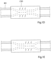
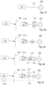
- FIGURES 1A, 1B and 1C schematically illustrate different states of operation of a generally designed apparatus according to the present invention, when the apparatus is applied on a wall portion of a bodily vas deference designated B0.
- the apparatus includes a constriction device and a stimulation device which are designated CSD, and a control device designated CD for controlling the constriction and stimulation devices CSD.
- FIGURE 1A shows the apparatus in an inactivation state, in which the constriction device does not constrict the vas deference B0 and the stimulation device does not stimulate the vas deference B0.
- FIGURES 1D and 1E show how the stimulation of the constricted wall portion can be cyclically varied between a first stimulation mode, in which the left area of the wall portion (see FIGURE 1D ) is stimulated, while the right area of the wall portion is not stimulated, and a second stimulation mode, in which the right area of the wall portion (see FIGURE 1E ) is stimulated, while the left area of the wall portion is not stimulated, in order to maintain over time satisfactory blood circulation in the constricted wall portion.
- FIGURES 1D and 1E only constitute a principle example of how the constricted wall portion of the vas deference B0 may be stimulated.
- more than two different areas of the constricted wall portion may be simultaneously stimulated in cycles or successively stimulated.
- groups of different areas of the constricted wall portion may be successively stimulated.
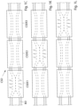
- FIGURES 1F, 1G and 1H illustrate different states of operation of a modification of the general embodiment shown in FIGURES 1A-1E , wherein the constriction and stimulation devices CSD include several separate constriction/stimulation elements, here three elements CSDE1, CSDE2 and CSDE3.
- FIGURE IF shows how the element CSDE1 in a first state of operation is activated to both constrict and stimulate the vas deference B0, so that the lumen of the vas deference B0 is closed, whereas the other two elements CSDE2 and CSDE3 are inactivated.
- FIGURE 1G shows how the element CSDE2 in a second following state of operation is activated, so that the lumen of the vas deference B0 is closed, whereas the other two elements CSDE1 and CSDE3 are inactivated.
- FIGURE IH shows how the element CSDE3 in a following third state of operation is activated, so that the lumen of the vas deference B0 is closed, whereas the other two elements CSDE1 and CSDE2 are inactivated.
- FIGURES 1I, 1K and 1L illustrate an alternative mode of operation of the modification of the general embodiment.
- FIGURE 1I shows how the element CSDE1 in a first state of operation is activated to both constrict and stimulate the vas deference B0, so that the lumen of the vas deference B0 is closed, whereas the other two elements CSDE2 and CSDE3 are activated to constrict but not stimulate the vas deference B0, so that the lumen of the vas deference B0 is not completely closed where the elements CSDE2 and CSDE3 engage the vas deference B0.
- FIGURE 1L shows how the element CSDE3 in a following third state of operation is activated to both constrict and stimulate the vas deference B0, so that the lumen of the vas deference B0 is closed, whereas the other two elements CSDE1 and CSDE2 are activated to constrict but not stimulate the vas deference B0, so that the lumen of the vas deference B0 is not completely closed where the elements CSDE1 and CSDE2 engage the vas deference B0.
- By shifting between the first, second and third states of operation either randomly or in accordance with a predetermined sequence, different portions of the vas deference can by temporarily stimulated while maintaining the lumen of the vas deference closed, whereby the risk of injuring the vas deference is reduced. It is also possible to activate the stimulation of the elements CSDE1-CSDE3 successively along the lumen of the vas deference B0 to move fluids in the lumen.
- FIGURES 2-4 show basic components of an embodiment of the apparatus according to the invention for controlling a flow of fluid in a lumen formed by a tissue wall of a patient's vas deference.
- the apparatus comprises a tubular housing 1 with open ends, a constriction device 2 arranged in the housing 1, a stimulation device 3 integrated in the constriction device 2, and a control device 4 (indicated in FIGURE 4 ) for controlling the constriction and stimulation devices 2 and 3.
- the constriction device 2 has two elongate clamping elements 5, 6, which are radially movable in the tubular housing 1 towards and away from each other between retracted positions, see FIGURE 3 , and clamping positions, see FIGURE 4 .
- the stimulation device 3 includes a multiplicity of electrical elements 7 positioned on the clamping elements 5, 6, so that the electrical elements 7 on one of the clamping elements 5, 6 face the electrical elements 7 on the other clamping element.
- the constriction and stimulation devices form a constriction/stimulation unit, in which the constriction and stimulation devices are integrated in a single piece.
- the constriction and stimulation devices may also be separate from each other.
- a structure may be provided for holding the electrical elements 7 in a fixed orientation relative to one another.
- the electrical elements 7 may include electrodes that are separately attached to the wall portion of the patient's vas deference.
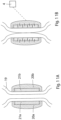
- FIGURES 5A - 5C illustrate in principle the function of the apparatus of FIGURE 2 when the apparatus is applied on a portion 8 of a tubular tissue wall of a patient's vas deference.
- FIGURE 5A shows the apparatus in a non-clamping state, in which the clamping elements 5, 6 are in their retracted positions and the wall portion 8 extends through the open ends of the housing 1 without being constricted by the clamping elements 5, 6.
- FIGURE 5B shows the apparatus in a clamping state, in which the clamping elements 5, 6 have been moved from their retracted positions to their clamping positions, in which the clamping elements 5, 6 gently constrict the wall portion 8 to a constricted state, in which the blood circulation in the constricted wall portion 8 is substantially unrestricted and the flow in the lumen of the wall portion 8 is restricted.
- FIGURE 5C shows the apparatus in a stimulation state, in which the clamping elements 5, 6 constrict the wall portion 8 and the electrical elements 7 of the stimulation device 3 electrically stimulate different areas of the wall portion 8, so that the wall portion 8 contracts (thickens) and closes the lumen.
- the control device 4 controls the stimulation device 3 to intermittently stimulate each area of the wall portion 8 during successive time periods, wherein each time period is short enough to maintain over time satisfactory blood circulation in the area. Furthermore, the control device 4 controls the stimulation of the areas of the wall portion 8, so that each area that currently is not stimulated restores substantially normal blood circulation before it is stimulated again. To maintain over time the effect of stimulation, i.e.
- the control device 4 controls the stimulation device 3 to stimulate one or more of the areas at a time and to shift the stimulation from one area to another over time.
- the control device 4 may control the stimulation device 3 to cyclically propagate the stimulation of the areas along the tubular wall portion 8, for example, in accordance with a determined stimulation pattern.
- the control device may control the stimulation device to, preferably cyclically, vary the intensity of the stimulation of the wall portion 8.
- the electrical elements 7 form a series of fourteen groups of electrical elements 7 extending longitudinally along each elongate clamping element 5 and 6, respectively, see FIGURE 2 .
- the electrical elements 7 of each group of electrical elements 7 form a first path of four electrical elements 7 positioned in a row on clamping element 5 and extending tranverse thereto, and a second path of four electrical elements 7 positioned in a row on clamping element 6 and extending tranverse thereto.
- the two paths of electrical elements 7 extend on mutual sides of the patient's vas deference.
- the control device 4 controls the stimulation device 3 to successively energize the groups of electrical elements 7 in the series of groups in a direction opposite to or, alternatively, in the same direction as that of the flow in the lumen of the patient's vas deference.
- the number of electrical elements 7 of each path of electrical elements 7 can be greater or smaller than four, and several parallel rows electrical elements 7 can form each path of electrical elements 7.
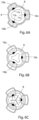
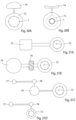
- FIGURES 6A - 6C show another embodiment of the invention which includes a tubular housing 9 and three elongate clamping elements 10a, 10b, 10c, which are radially movable in the tubular housing 9 towards and away from a central axis thereof between retracted positions, see FIGURE 6A , and clamping positions, see FIGURE 6B .
- the three clamping elements 10a-10c are symmetrically disposed around the central axis of the housing 9.
- the stimulation device of this embodiment includes electrical elements 11a, 11 b, 11c that form a series of groups of elements extending longitudinally along the elongate clamping elements 10a-10c, wherein the electrical elements 11a - 11c of each group of electrical elements form a path of three electrical elements 11a, 11b and 11c extending circumferentially around the central axis of the housing 9.
- the three electrical elements 11a - 11c of each group are positioned on the three clamping elements 10a-10c, respectively.
- the path of three electrical elements 11a-11c extends around the patient's vas deference.
- the number of electrical elements 11a-11c of each path of electrical elements can be greater than three, and several parallel rows electrical elements 11a-11c can form each path of electrical elements.
- FIGURES 7A and 7B show different steps of an electric stimulation mode performed by the apparatus of FIGURE 2 while the clamping elements 5, 6 of the apparatus are constricting a portion of a tubular tissue wall of a patient's vas deference 12 to restrict the flow in the lumen 13 of the vas deference 12.
- FIGURES 7A, 7B show only the clamping elements 5, 6 of the constriction device 2 .
- FIGURE 7A illustrates how energized electrical elements 7 of groups of electrical elements electrically stimulate a first portion 14 and a second portion 15 of the tubular wall to contract and close the lumen 13.
- FIGURE 7B illustrates how energized electrical elements 7 of other groups of electrical elements electrically stimulate a third portion 16 of the tubular wall different from the first and second portions to contract and close the lumen 13, while the electrical stimulation of the first and second portions 14, 15 of the tubular wall has been ceased, so that substantially normal blood circulation in the first and second portions is restored.
- the electric stimulation of the constricted tubular wall is shifted over time from one portion of the tubular wall to another to insure recurrent restoration of blood circulation in the constricted tubular wall.
- the control device 4 controls the stimulation device 3 to energize the electrical elements 7 with electric biphasic pulses, i.e. , combined positive and negative pulses.
- the desired stimulation effect is achieved by varying different pulse parameters.
- the control device 4 controls the stimulation device 3 to vary the pulse amplitude (voltage), the off time period between successive pulses, the pulse duration and the pulse repetition frequency.
- the pulse current should be between 1 to 30mA.
- a pulse current of about 5mA and a pulse duration of about 300 ⁇ s are suitable, whereas a pulse current of about 20mA and a pulse duration of about 30 ⁇ s are suitable for muscular stimulation.
- the pulse repetition frequency suitably is about 10Hz.
- a pulse combination including a negative pulse PS of short duration and high amplitude (voltage), and a positive pulse PL of long duration and low amplitude following the negative pulse may be cyclically repeated to form a pulse train of such pulse combinations.
- the energy content of the negative pulse PS should be substantially equal to the energy content of the positive pulse PL.
- FIGURE 8B is a pulse/time diagram showing a modification of the electric stimulation shown in FIGURE 8A .
- the pulse combination of FIGURE 8A is mixed with a pulse train combination having a first relatively long pulse train PTL of high frequency/low amplitude pulses, appearing simultaneously with the positive pulse PL of the pulse combination of FIGURE 8A , and a second relatively short pulse train PTS of high frequency/low amplitude appearing simultaneously with the negative pulse PS of the pulse combination shown in FIGURE 8A .
- the high frequency/low amplitudes pulse trains PTL and PTS are superimposed on the positive and negative pulses PL and PS of FIGURE 8A , as illustrated in FIGURE 8B .
- the pulse configuration of FIGURE 8B and variations thereof, is beneficial to use in connection with the stimulation of particular human vas deferences, in order to achieve the desired stimulation effect.
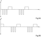
- the electric pulses form pulse trains, as illustrated in the Pulse/time diagrams P/t of FIGURES 9A, 9B , 9C and 9D.
- the Pulse/time diagram P/t of FIGURE 9A represents an individual area of the wall portion of the patient's tubular vas deference which is stimulated with a pulse train 18A.
- the pulse train 18A includes three initial negative pulses, each of which is of short duration and high amplitude (voltage), and one positive pulse of long duration and low amplitude following the negative pulses. After a delay to enable the area of the vas deference to restore substantially normal blood circulation, the pulse train 18A is repeated.
- the pulse/time diagrams P/t of FIGURES 10A and 10B represent two different areas of the wall portion, which are stimulated with cyclically repeated pulse trains 18C and 18D, respectively, having the same configuration.
- Each pulse train 18C, 18D includes two initial negative pulses, each of which is of short duration and high amplitude (voltage), and one positive pulse of long duration and low amplitude following the two negative pulses.
- the pulse trains 18C and 18D are shifted relative to each other, so that they do not overlap each other.
- the off time period between adjacent pulse trains 18C is longer than the duration of pulse train 18D and the off time period between adjacent pulse trains 18D is longer than the duration of pulse train 18C.
- the pulse trains 18A, 18B, 18C and 18D can be configured in many different ways.
- the control device 4 can control the stimulation device 2 to vary the length of each pulse train, the repetition frequency of the pulse trains, the number of pulses of each pulse train, and/or the off time periods between the pulse trains.
- the control device 4 controls each off time period between the pulse trains to last long enough to restore substantially normal blood circulation in the area that just has been stimulated before that area again is stimulated with electric pulses.
- the control device 4 controls the pump 25 to pump hydraulic fluid from the reservoir 23 to the chambers 22a, 22b to move the clamping elements 5, 6 against the wall portion 8, whereby the tubular wall portion 8 is constricted, see FIGURE 12B , and to pump hydraulic fluid from the chambers 22a, 22b to the reservoir 23 to move the clamping elements 5, 6 away from the wall portion 8, whereby the tubular wall 8 is released, see FIGURE 12A .
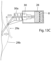
- the motor 29 may be omitted and the telescopic device 30 be modified for manual operation, as shown in FIGURE 13C .
- a spring 30a may be provided acting to keep the telescopic device 30 expanded to force the clamping element 28 against the wall portion 8.
- the mechanical operation means may include a subcutaneously implanted lever mechanism 29a that is operatively connected to the telescopic device 30. The patient may push the lever mechanism 29a through the patient's skin 29b to pull the telescopic device 30 against the action of the spring 30a to the retracted position of the telescopic device 30, as indicated in phantom lines. When the patient releases the lever mechanism 29a, the spring 30a expands the telescopic device 30, whereby clamping element 28 is forced against the wall portion 8.
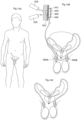
- FIGURE 14A illustrates the embodiment of FIGURE 2 applied on vas deference for male contraception.
- FIGURE 14A shows a restriction of vas deference (vasa deferentia) with the controller.
- FIGURE 14B depicts only the restriction devices of the invention.
- Fig. 14A shows the apparatus having with two restriction devices 660A and 660B in arrangement with the two vas deference to perform restriction of these lumens to prevent from that sperms are transported through the vas deference.
- Restriction devices 660A and 660B operates both to constrict and to stimulate vas deference.
- the restriction devices are operatively connected to the controller 600 having a control device 650 that is subcutaneously implanted.
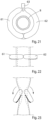
- FIGURES 15-17 show a mechanically operable constriction device having an elongated constriction member in the form of a circular resilient core 37 with two overlapping end portions 38, 39.
- the core 37 defines a substantially circular restriction opening and is enclosed in an elastic soft hose 40 except at a releasable and lockable joint 41 of the core 37, which when released enables application of the core 37 with its hose 40 around a portion of a tubular tissue wall of a patient's vas deference.
- the materials of all of these elements are bio-compatible so that the patient' body will not reject them.
- An operation device 42 for mechanically operating the longitudinal extension of the core 37 to change the size of the restriction opening comprises a drive wheel 43 in frictional engagement with the overlapping end portions 38, 39 of the core 37.
- the power supply unit 49 can be controlled to power the electric motor 47 to turn the drive wheel 43 in one direction to reduce the diameter of the core 37, so that the wall portion is constricted, or to turn the drive wheel 43 in the opposite direction to increase the diameter of the core 37, so that the wall portion is released.
- the constriction/stimulation unit 200 is applied on a wall portion 8 of a tubular tissue wall of a patient's vas deference, so that the short clamping elements 201, 202 are positioned at an upstream end of the wall portion 8, whereas the short clamping elements 203, 204 202 are positioned at a downstream end of the wall portion 8.
- the upstream end of the wall portion 8 is to the left and the downstream end of the wall portion 8 is to the right.
- the control device 4 controls the pair of short clamping elements 201, 202, the pair of elongate clamping elements 5, 6 and the pair of short elements 203, 204 to constrict and release the wall portion 8 independently of one another.
- the control device also controls the electrical elements 7 on a clamping element that is constricting the wall portion to stimulate the constricted wall portion 8 with electric pulses to cause contraction of the wall portion 8, so that the lumen of the wall portion 8 is closed.
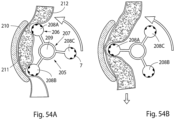
- FIGURES 55A, 55B and 55C show another mechanically operable constriction device 213 for use in the apparatus of the invention.
- the constriction device 213 includes a first ring-shaped holder 214 applied on a tubular vas deference 8 of a patient and a second ring-shaped holder 215 also applied on the vas deference 8 spaced apart from holder 214.
- There are elastic strings 216 (here twelve strings) that extend in parallel along the tubular vas deference 8 and interconnect the two holders 213, 214 without contacting the vas deference 8.
- FIGURE 55A illustrate an inactivated state of the constriction device 213 in which the vas deference 8 is not constricted.
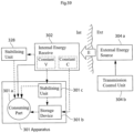
- the internal energy receiver is adapted to directly or indirectly supply received energy to the energy consuming components of the constriction/stimulation unit 301 via a switch 326.
- An energy balance is determined between the energy received by the internal energy receiver 302 and the energy used for the constriction/stimulation unit 301, and the transmission of wireless energy is then controlled based on the determined energy balance.
- the energy balance thus provides an accurate indication of the correct amount of energy needed, which is sufficient to operate the constriction/stimulation unit 301 properly, but without causing undue temperature rise.
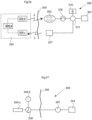
- the energy receiver comprises an energy-transforming device 302 located inside the patient, preferably just beneath the patient's skin 305.
- the implanted energy-transforming device 302 may be placed in the abdomen, thorax, muscle fascia (e.g. in the abdominal wall), subcutaneously, or at any other suitable location.
- the implanted energy-transforming device 302 is adapted to receive wireless energy E transmitted from the external source of energy 304a provided in an external energy-transmission device 304 located outside the patient's skin 305 in the vicinity of the implanted energy-transforming device 302.
- the wireless energy E may generally be transferred by means of any suitable Transcutaneous Energy Transfer (TET) device, such as a device including a primary coil arranged in the external source of energy 304a and an adjacent secondary coil arranged in the implanted energy-transforming device 302.
- TET Transcutaneous Energy Transfer
- TET Transcutaneous Energy Transfer
- the primary coil When an electric current is fed through the primary coil, energy in the form of a voltage is induced in the secondary coil which can be used to power the implanted energy consuming components of the apparatus, e.g. after storing the incoming energy in an implanted source of energy, such as a rechargeable battery or a capacitor.
- an implanted source of energy such as a rechargeable battery or a capacitor.
- the present invention is generally not limited to any particular energy transfer technique,
- TET devices or energy sources and any kind of wireless energy may be used.
- a control device includes an external control unit 304b that controls the external source of energy 304a based on the determined energy balance to regulate the amount of transferred energy.
- the energy balance and the required amount of energy is determined by means of a determination device including an implanted internal control unit 315 connected between the switch 326 and the constriction/stimulation unit 301.
- the internal control unit 315 may thus be arranged to receive various measurements obtained by suitable sensors or the like, not shown, measuring certain characteristics of the constriction/stimulation unit 301, somehow reflecting the required amount of energy needed for proper operation of the constriction/stimulation unit 301.
- the current condition of the patient may also be detected by means of suitable measuring devices or sensors, in order to provide parameters reflecting the patient's condition.
- characteristics and/or parameters may be related to the current state of the constriction/stimulation unit 301, such as power consumption, operational mode and temperature, as well as the patient's condition reflected by parametyers such as: body temperature, blood pressure, heartbeats and breathing.
- parametyers such as: body temperature, blood pressure, heartbeats and breathing.
- Other kinds of physical parameters of the patient and functional parameters of the device are described elsewhere.
- a source of energy in the form of an accumulator 316 may optionally be connected to the implanted energy-transforming device 302 via the control unit 315 for accumulating received energy for later use by the constriction/stimulation unit 301.
- characteristics of such an accumulator also reflecting the required amount of energy, may be measured as well.
- the accumulator may be replaced by a rechargeable battery, and the measured characteristics may be related to the current state of the battery, any electrical parameter such as energy consumption voltage, temperature, etc.
- the battery should be charged optimally by receiving a correct amount of energy from the implanted energy-transforming device 302, i.e. not too little or too much.
- the accumulator may also be a capacitor with corresponding characteristics.
- battery characteristics may be measured on a regular basis to determine the current state of the battery, which then may be stored as state information in a suitable storage means in the internal control unit 315.
- state information in a suitable storage means in the internal control unit 315.
- the internal control unit 315 of the determination device is adapted to determine the energy balance and/or the currently required amount of energy, (either energy per time unit or accumulated energy) based on measurements made by the above-mentioned sensors or measuring devices of the apparatus, or the patient, or an implanted source of energy if used, or any combination thereof.
- the internal control unit 315 is further connected to an internal signal transmitter 327, arranged to transmit a control signal reflecting the determined required amount of energy, to an external signal receiver 304c connected to the external control unit 304b.
- the amount of energy transmitted from the external source of energy 304a may then be regulated in response to the received control signal.
- the amount of transferred energy can generally be regulated by adjusting various transmission parameters in the external source of energy 304a, such as voltage, current, amplitude, wave frequency and pulse characteristics.
- This system may also be used to obtain information about the coupling factors between the coils in a TET system even to calibrate the system both to find an optimal place for the external coil in relation to the internal coil and to optimize energy transfer. Simply comparing in this case the amount of energy transferred with the amount of energy received. For example if the external coil is moved the coupling factor may vary and correctly displayed movements could cause the external coil to find the optimal place for energy transfer.
- the external coil is adapted to calibrate the amount of transferred energy to achieve the feedback information in the determination device before the coupling factor is maximized.
- the energy system of the present invention comprises an implantable internal energy receiver for receiving wireless energy, the energy receiver having an internal first coil and a first electronic circuit connected to the first coil, and an external energy transmitter for transmitting wireless energy, the energy transmitter having an external second coil and a second electronic circuit connected to the second coil.
- the external second coil of the energy transmitter transmits wireless energy which is received by the first coil of the energy receiver.
- FIGURE 57 Although wireless transfer of energy for operating the apparatus has been described above to enable non-invasive operation, it will be appreciated that the apparatus can be operated with wire bound energy as well.
- an external switch 326 is interconnected between the external source of energy 304a and an operation device such as an electric motor 307 operating the constriction/stimulation unit 301.
- An external control unit 304b controls the operation of the external switch 326 to effect proper operation of the constriction/stimulation unit 301.
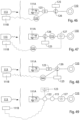
- FIGURE 58 illustrates different embodiments for how received energy can be supplied to and used by the constriction/stimulation unit 301.
- an internal energy receiver 302 receives wireless energy E from an external source of energy 304a which is controlled by a transmission control unit 304b.
- the internal energy receiver 302 may comprise a constant voltage circuit, indicated as a dashed box “constant V" in FIGURE 58 , for supplying energy at constant voltage to the constriction/stimulation unit 301.
- the internal energy receiver 302 may further comprise a constant current circuit, indicated as a dashed box "constant C" in the figure, for supplying energy at constant current to the constriction/stimulation unit 301.
- the energy supplied from the internal energy receiver 302 may further be accumulated and/or stabilized by a separate energy stabilizing unit 328 located outside the constriction/stimulation unit 301, before being consumed and/or stored by the constriction/stimulation unit 301.
- the energy stabilizing unit 328 may be integrated in the internal energy receiver 302. In either case, the energy stabilizing unit 328 may comprise a constant voltage circuit and/or a constant current circuit.
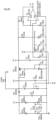
- FIGURE 59 schematically shows an energy balance measuring circuit of one of the proposed designs of the apparatus for controlling transmission of wireless energy, or energy balance.
- the circuit has an output signal centered on 2.5V and proportionally related to the energy imbalance. The derivative of this signal shows if the value goes up and down and how fast such a change takes place. If the amount of received energy is lower than the energy used by implanted components of the apparatus, more energy is transferred and thus charged into the source of energy.
- the output signal from the circuit is typically fed to an A/D converter and converted into a digital format. The digital information can then be sent to the external energy-transmission device allowing it to adjust the level of the transmitted energy.
- Another possibility is to have a completely analog system that uses comparators comparing the energy balance level with certain maximum and minimum thresholds sending information to external energy-transmission device if the balance drifts out of the max/min window.
- the schematic FIGURE 59 shows a circuit implementation for a system that transfers energy to the implanted energy components of the apparatus of the present invention from outside of the patient's body using inductive energy transfer.
- An inductive energy transfer system typically uses an external transmitting coil and an internal receiving coil.
- the receiving coil, L1 is included in the schematic FIGURE 59 ; the transmitting parts of the system are excluded.
- FIGURE 59 the symbols Y1, Y2, Y3 and so on symbolize test points within the circuit.
- the components in the diagram and their respective values are values that work in this particular implementation which of course is only one of an infinite number of possible design solutions.
- Energy to power the circuit is received by the energy receiving coil L1. Energy to implanted components is transmitted in this particular case at a frequency of 25 kHz.
- the energy balance output signal is present at test point Y1.
- FIGURES 56 , 58 and 59 identify a general method for controlling transmission of wireless energy to implanted energy consuming components of the apparatus of the present invention. Such a method will be defined in general terms in the following.
- a method for controlling transmission of wireless energy supplied to implanted energy consuming components of an apparatus as described above.
- the wireless energy E is transmitted from an external source of energy located outside the patient and is received by an internal energy receiver located inside the patient, the internal energy receiver being connected to the implanted energy consuming components of the apparatus for directly or indirectly supplying received energy thereto.
- An energy balance is determined between the energy received by the internal energy receiver and the energy used for the operation of the implanted parts of the apparatus.
- the transmission of wireless energy E from the external source of energy is then controlled based on the determined energy balance.
- the wireless energy may be transmitted inductively from a primary coil in the external source of energy to a secondary coil in the internal energy receiver.
- a change in the energy balance may be detected to control the transmission of wireless energy based on the detected energy balance change.
- a difference may also be detected between energy received by the internal energy receiver and energy used for the operation of the implanted parts of the apparatus, to control the transmission of wireless energy based on the detected energy difference.
- the amount of transmitted wireless energy may be decreased if the detected energy balance change implies that the energy balance is increasing, or vice versa.
- the decrease/increase of energy transmission may further correspond to a detected change rate.
- the amount of transmitted wireless energy may further be decreased if the detected energy difference implies that the received energy is greater than the used energy, or vice versa.
- the decrease/increase of energy transmission may then correspond to the magnitude of the detected energy difference.
- the energy used for the operation of the implanted parts of the apparatus be consumed to operate the implanted parts of the apparatus and/or stored in at least one implanted energy storage device of the apparatus.
- the energy may be transmitted for consumption and storage according to a transmission rate per time unit which is determined based on said parameters.
- the total amount of transmitted energy may also be determined based on said parameters.
- the integral may be determined for a monitored voltage and/or current related to the energy balance.
- the derivative When the derivative is determined over time of a measured electrical parameter related to the amount of consumed and/or stored energy, the derivative may be determined for a monitored voltage and/or current related to the energy balance.
- the transmission of wireless energy from the external source of energy may be controlled by applying to the external source of energy electrical pulses from a first electric circuit to transmit the wireless energy, the electrical pulses having leading and trailing edges, varying the lengths of first time intervals between successive leading and trailing edges of the electrical pulses and/or the lengths of second time intervals between successive trailing and leading edges of the electrical pulses, and transmitting wireless energy, the transmitted energy generated from the electrical pulses having a varied power, the varying of the power depending on the lengths of the first and/or second time intervals.
- the frequency of the electrical pulses may be substantially constant when varying the first and/or second time intervals.
- the electrical pulses may remain unchanged, except for varying the first and/or second time intervals.
- the amplitude of the electrical pulses may be substantially constant when varying the first and/or second time intervals. Further, the electrical pulses may be varied by only varying the lengths of first time intervals between successive leading and trailing edges of the electrical pulses.
- a train of two or more electrical pulses may be supplied in a row, wherein when applying the train of pulses, the train having a first electrical pulse at the start of the pulse train and having a second electrical pulse at the end of the pulse train, two or more pulse trains may be supplied in a row, wherein the lengths of the second time intervals between successive trailing edge of the second electrical pulse in a first pulse train and leading edge of the first electrical pulse of a second pulse train are varied
- the electrical pulses When applying the electrical pulses, the electrical pulses may have a substantially constant current and a substantially constant voltage.
- the electrical pulses may also have a substantially constant current and a substantially constant voltage. Further, the electrical pulses may also have a substantially constant frequency.
- the electrical pulses within a pulse train may likewise have a substantially constant frequency.
- the circuit formed by the first electric circuit and the external source of energy may have a first characteristic time period or first time constant, and when effectively varying the transmitted energy, such frequency time period may be in the range of the first characteristic time period or time constant or shorter.
- FIGURES 56 , 58 and 59 also identify general features for controlling transmission of wireless energy to implanted energy consuming components of the apparatus of the present invention. Such features of the apparatus will be defined in general terms in the following.
- the apparatus comprises a control device for controlling the transmission of wireless energy from an energy-transmission device, and an implantable internal energy receiver for receiving the transmitted wireless energy, the internal energy receiver being connected to implantable energy consuming components of the apparatus for directly or indirectly supplying received energy thereto.
- the apparatus further comprises a determination device adapted to determine an energy balance between the energy received by the internal energy receiver and the energy used for the implantable energy consuming components of the apparatus, wherein the control device controls the transmission of wireless energy from the external energy-transmission device, based on the energy balance determined by the determination device.
- apparatus of the invention may comprise any of the following features:
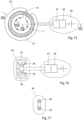
- Fig. 60A shows a restriction of vas deference (vasa deferentia) with the controller.
- Fig. 60B depicts only the restriction devices of the invention.
- Fig. 60A shows the apparatus having with two restriction devices 660A and 660B in arrangement with the two vas deference to perform restriction of these lumens to prevent from that sperms are transported through the vas deference.
- Restriction devices 660A and 660B operates both to constrict and to stimulate vas deference.
- the restriction devices are operatively connected to the controller 600 having a control device 650 that is subcutaneously implanted.
- the control device has an energy source 651 for supplying energy consuming parts of the apparatus with energy.
- the energy source is supplied with wireless energy from an external energizer unit 620.
- the controller further includes an external remote control unit 630 capable of communicating with the control device 650 and an internal control unit 640.
- the control device further has an external part 652 for including functions needed for external operation such as an injection port for supply of hydraulic fluid when the constriction is hydraulically operated and an activation/deactivation button for operating the restriction device.
Landscapes
- Health & Medical Sciences (AREA)
- Life Sciences & Earth Sciences (AREA)
- Engineering & Computer Science (AREA)
- Biomedical Technology (AREA)
- Animal Behavior & Ethology (AREA)
- General Health & Medical Sciences (AREA)
- Public Health (AREA)
- Veterinary Medicine (AREA)
- Heart & Thoracic Surgery (AREA)
- Urology & Nephrology (AREA)
- Vascular Medicine (AREA)
- Nuclear Medicine, Radiotherapy & Molecular Imaging (AREA)
- Cardiology (AREA)
- Surgery (AREA)
- Reproductive Health (AREA)
- Radiology & Medical Imaging (AREA)
- Oral & Maxillofacial Surgery (AREA)
- Transplantation (AREA)
- Gastroenterology & Hepatology (AREA)
- Medical Informatics (AREA)
- Molecular Biology (AREA)
- Electrotherapy Devices (AREA)
- Selective Calling Equipment (AREA)
- Orthopedics, Nursing, And Contraception (AREA)
- Prostheses (AREA)
Applications Claiming Priority (6)
| Application Number | Priority Date | Filing Date | Title |
|---|---|---|---|
| US96071507P | 2007-10-11 | 2007-10-11 | |
| EP24199379.9A EP4454698A3 (de) | 2007-10-11 | 2008-10-10 | Vorrichtung zur männlichen kontrazeption |
| EP08836877.4A EP2214605B1 (de) | 2007-10-11 | 2008-10-10 | Gerät für männliche kontrazeption |
| EP24170170.5A EP4410359A2 (de) | 2007-10-11 | 2008-10-10 | Vorrichtung zur männlichen kontrazeption |
| PCT/SE2008/000580 WO2009048389A1 (en) | 2007-10-11 | 2008-10-10 | An apparatus for male contraception |
| EP21163203.9A EP3912600A1 (de) | 2007-10-11 | 2008-10-10 | Vorrichtung für männliche verhütung |
Related Parent Applications (4)
| Application Number | Title | Priority Date | Filing Date |
|---|---|---|---|
| EP08836877.4A Division EP2214605B1 (de) | 2007-10-11 | 2008-10-10 | Gerät für männliche kontrazeption |
| EP24199379.9A Division EP4454698A3 (de) | 2007-10-11 | 2008-10-10 | Vorrichtung zur männlichen kontrazeption |
| EP21163203.9A Division EP3912600A1 (de) | 2007-10-11 | 2008-10-10 | Vorrichtung für männliche verhütung |
| EP24170170.5A Division EP4410359A2 (de) | 2007-10-11 | 2008-10-10 | Vorrichtung zur männlichen kontrazeption |
Publications (1)
| Publication Number | Publication Date |
|---|---|
| EP4578423A2 true EP4578423A2 (de) | 2025-07-02 |
Family
ID=54208479
Family Applications (8)
| Application Number | Title | Priority Date | Filing Date |
|---|---|---|---|
| EP24199379.9A Withdrawn EP4454698A3 (de) | 2007-10-11 | 2008-10-10 | Vorrichtung zur männlichen kontrazeption |
| EP08836877.4A Active EP2214605B1 (de) | 2007-10-11 | 2008-10-10 | Gerät für männliche kontrazeption |
| EP21163204.7A Withdrawn EP3922219A3 (de) | 2007-10-11 | 2008-10-10 | Vorrichtung für männliche verhütung |
| EP21163198.1A Ceased EP3868440A1 (de) | 2007-10-11 | 2008-10-10 | Vorrichtung für männliche harninkontinenzkontrolle |
| EP21163203.9A Withdrawn EP3912600A1 (de) | 2007-10-11 | 2008-10-10 | Vorrichtung für männliche verhütung |
| EP24170170.5A Withdrawn EP4410359A2 (de) | 2007-10-11 | 2008-10-10 | Vorrichtung zur männlichen kontrazeption |
| EP21163200.5A Withdrawn EP3912599A1 (de) | 2007-10-11 | 2008-10-10 | Vorrichtung für männliche verhütung |
| EP25159535.1A Withdrawn EP4578423A2 (de) | 2007-10-11 | 2008-10-10 | Vorrichtung zur männlichen kontrazeption |
Family Applications Before (7)
| Application Number | Title | Priority Date | Filing Date |
|---|---|---|---|
| EP24199379.9A Withdrawn EP4454698A3 (de) | 2007-10-11 | 2008-10-10 | Vorrichtung zur männlichen kontrazeption |
| EP08836877.4A Active EP2214605B1 (de) | 2007-10-11 | 2008-10-10 | Gerät für männliche kontrazeption |
| EP21163204.7A Withdrawn EP3922219A3 (de) | 2007-10-11 | 2008-10-10 | Vorrichtung für männliche verhütung |
| EP21163198.1A Ceased EP3868440A1 (de) | 2007-10-11 | 2008-10-10 | Vorrichtung für männliche harninkontinenzkontrolle |
| EP21163203.9A Withdrawn EP3912600A1 (de) | 2007-10-11 | 2008-10-10 | Vorrichtung für männliche verhütung |
| EP24170170.5A Withdrawn EP4410359A2 (de) | 2007-10-11 | 2008-10-10 | Vorrichtung zur männlichen kontrazeption |
| EP21163200.5A Withdrawn EP3912599A1 (de) | 2007-10-11 | 2008-10-10 | Vorrichtung für männliche verhütung |
Country Status (5)
| Country | Link |
|---|---|
| EP (8) | EP4454698A3 (de) |
| AU (1) | AU2008311442B2 (de) |
| CA (1) | CA2739840A1 (de) |
| ES (1) | ES2970012T3 (de) |
| WO (1) | WO2009048389A1 (de) |
Families Citing this family (6)
| Publication number | Priority date | Publication date | Assignee | Title |
|---|---|---|---|---|
| US8992409B2 (en) | 2007-10-11 | 2015-03-31 | Peter Forsell | Method for controlling flow in a bodily organ |
| EP4595905A3 (de) | 2007-10-11 | 2025-08-20 | Implantica Patent Ltd. | Vorrichtung zur steuerung des flusses in einem körperorgan |
| EP4454698A3 (de) | 2007-10-11 | 2025-01-15 | Implantica Patent Ltd. | Vorrichtung zur männlichen kontrazeption |
| US11123171B2 (en) * | 2008-10-10 | 2021-09-21 | Peter Forsell | Fastening means for implantable medical control assembly |
| EP3120896A1 (de) | 2008-10-10 | 2017-01-25 | Kirk Promotion LTD. | System, vorrichtung und verfahren zur behandlung einer patientin mit sexueller dysfunktion |
| CA2776506C (en) * | 2008-10-10 | 2023-05-23 | Peter Forsell | An apparatus for temporary male contraception |
Citations (3)
| Publication number | Priority date | Publication date | Assignee | Title |
|---|---|---|---|---|
| US4942668A (en) | 1988-05-11 | 1990-07-24 | Zircon International, Inc. | Digital inclinometer |
| US5900909A (en) | 1995-04-13 | 1999-05-04 | Eastman Kodak Company | Electronic still camera having automatic orientation sensing and image correction |
| US6513528B2 (en) | 2000-11-22 | 2003-02-04 | John Burton | Method and device for vas occlusion |
Family Cites Families (19)
| Publication number | Priority date | Publication date | Assignee | Title |
|---|---|---|---|---|
| US3817237A (en) * | 1972-08-24 | 1974-06-18 | Medtronic Inc | Regulatory apparatus |
| US20050137644A1 (en) * | 1998-10-26 | 2005-06-23 | Boveja Birinder R. | Method and system for vagal blocking and/or vagal stimulation to provide therapy for obesity and other gastrointestinal disorders |
| US6073050A (en) * | 1998-11-10 | 2000-06-06 | Advanced Bionics Corporation | Efficient integrated RF telemetry transmitter for use with implantable device |
| AUPQ202699A0 (en) * | 1999-08-04 | 1999-08-26 | University Of Melbourne, The | Prosthetic device for incontinence |
| US7648455B2 (en) * | 2000-02-10 | 2010-01-19 | Obtech Medical Ag | Controlled urinary incontinence treatment |
| EP1759665B1 (de) * | 2000-02-11 | 2014-10-22 | Urologica AG | Vorrichtung zur Inkontinenzbehandlung |
| EP1263355B1 (de) | 2000-02-14 | 2005-04-27 | Potencia Medical AG | Hydraulisches gerät zur behandlung von harninkontinenz |
| US7499753B2 (en) * | 2001-06-28 | 2009-03-03 | Urologica Ag | Urinary Dysfunction Treatment Apparatus |
| WO2004002572A1 (en) * | 2002-06-28 | 2004-01-08 | Advanced Bionics Corporation | Microstimulator having self-contained power source and bi-directional telemetry system |
| CN2577790Y (zh) * | 2002-10-23 | 2003-10-08 | 李育林 | 光纤激光节育装置 |
| ATE356595T1 (de) * | 2003-01-31 | 2007-04-15 | Potencia Medical Ag | Elektrisch bedienbare vorrichtung zur impotenzbehandlung |
| US20050288740A1 (en) * | 2004-06-24 | 2005-12-29 | Ethicon Endo-Surgery, Inc. | Low frequency transcutaneous telemetry to implanted medical device |
| CA2507142A1 (en) * | 2005-04-25 | 2006-10-25 | Mohammad Nadeem Qadir | Apparatus, devices and methods for contraception, conception and pregnancy |
| US7835796B2 (en) * | 2005-04-29 | 2010-11-16 | Cyberonics, Inc. | Weight loss method and device |
| US7899540B2 (en) * | 2005-04-29 | 2011-03-01 | Cyberonics, Inc. | Noninvasively adjustable gastric band |
| US20090306460A1 (en) * | 2005-08-15 | 2009-12-10 | Continence Control Systems International Pty Ltd. | Method and Apparatus for Controlling a Bodily Function |
| EP2010062A2 (de) * | 2006-04-13 | 2009-01-07 | Elena Kachiguina | Verfahren und vorrichtung für männliche verhütung |
| EP4595905A3 (de) | 2007-10-11 | 2025-08-20 | Implantica Patent Ltd. | Vorrichtung zur steuerung des flusses in einem körperorgan |
| EP4454698A3 (de) | 2007-10-11 | 2025-01-15 | Implantica Patent Ltd. | Vorrichtung zur männlichen kontrazeption |
-
2008
- 2008-10-10 EP EP24199379.9A patent/EP4454698A3/de not_active Withdrawn
- 2008-10-10 EP EP08836877.4A patent/EP2214605B1/de active Active
- 2008-10-10 EP EP21163204.7A patent/EP3922219A3/de not_active Withdrawn
- 2008-10-10 EP EP21163198.1A patent/EP3868440A1/de not_active Ceased
- 2008-10-10 EP EP21163203.9A patent/EP3912600A1/de not_active Withdrawn
- 2008-10-10 CA CA2739840A patent/CA2739840A1/en not_active Abandoned
- 2008-10-10 WO PCT/SE2008/000580 patent/WO2009048389A1/en not_active Ceased
- 2008-10-10 EP EP24170170.5A patent/EP4410359A2/de not_active Withdrawn
- 2008-10-10 EP EP21163200.5A patent/EP3912599A1/de not_active Withdrawn
- 2008-10-10 AU AU2008311442A patent/AU2008311442B2/en active Active
- 2008-10-10 ES ES08836877T patent/ES2970012T3/es active Active
- 2008-10-10 EP EP25159535.1A patent/EP4578423A2/de not_active Withdrawn
Patent Citations (3)
| Publication number | Priority date | Publication date | Assignee | Title |
|---|---|---|---|---|
| US4942668A (en) | 1988-05-11 | 1990-07-24 | Zircon International, Inc. | Digital inclinometer |
| US5900909A (en) | 1995-04-13 | 1999-05-04 | Eastman Kodak Company | Electronic still camera having automatic orientation sensing and image correction |
| US6513528B2 (en) | 2000-11-22 | 2003-02-04 | John Burton | Method and device for vas occlusion |
Also Published As
| Publication number | Publication date |
|---|---|
| EP3912600A1 (de) | 2021-11-24 |
| EP4454698A2 (de) | 2024-10-30 |
| EP2214605B1 (de) | 2023-11-22 |
| AU2008311442A1 (en) | 2009-04-16 |
| EP2214605A1 (de) | 2010-08-11 |
| EP2214605A4 (de) | 2017-11-22 |
| EP4410359A2 (de) | 2024-08-07 |
| EP3868440A1 (de) | 2021-08-25 |
| EP2214605C0 (de) | 2023-11-22 |
| WO2009048389A1 (en) | 2009-04-16 |
| EP3912599A1 (de) | 2021-11-24 |
| EP4454698A3 (de) | 2025-01-15 |
| EP3922219A3 (de) | 2022-06-08 |
| AU2008311442B2 (en) | 2015-01-29 |
| CA2739840A1 (en) | 2009-04-16 |
| EP3922219A2 (de) | 2021-12-15 |
| ES2970012T3 (es) | 2024-05-23 |
Similar Documents
| Publication | Publication Date | Title |
|---|---|---|
| US20240009454A1 (en) | Method for controlling flow of sperms in a uterine tube | |
| US20240407942A1 (en) | Method for controlling flow of eggs in a uretine tube | |
| US20210205122A1 (en) | Apparatus for controlling flow in a bodily organ | |
| EP4512378A2 (de) | Vorrichtung zur steuerung des flusses in einem körperorgan | |
| EP2214777B1 (de) | Gerät zur kontrolle des durchflusses von blut in einem gefäss | |
| EP2214578B1 (de) | Gerät zur kontrolle des durchflusses von spermien in einem eileiter | |
| WO2009048394A2 (en) | Apparatus for controlling flow of sperms in an uterine tube | |
| EP2214605B1 (de) | Gerät für männliche kontrazeption | |
| EP3912594B1 (de) | Vorrichtung zur steuerung des flusses von eizellen in einem eileiter | |
| EP2214601B1 (de) | Gerät zur kontrolle des nahrungsflusses durch den magen eines patienten | |
| EP2214606B1 (de) | Männliches kontrazeptionsgerät | |
| EP4023285A1 (de) | Vorrichtung zur kontrolle des flusses des darminhaltes im darm eines patienten |
Legal Events
| Date | Code | Title | Description |
|---|---|---|---|
| PUAI | Public reference made under article 153(3) epc to a published international application that has entered the european phase |
Free format text: ORIGINAL CODE: 0009012 |
|
| STAA | Information on the status of an ep patent application or granted ep patent |
Free format text: STATUS: THE APPLICATION HAS BEEN PUBLISHED |
|
| AC | Divisional application: reference to earlier application |
Ref document number: 2214605 Country of ref document: EP Kind code of ref document: P Ref document number: 3912600 Country of ref document: EP Kind code of ref document: P Ref document number: 4410359 Country of ref document: EP Kind code of ref document: P Ref document number: 4454698 Country of ref document: EP Kind code of ref document: P |
|
| AK | Designated contracting states |
Kind code of ref document: A2 Designated state(s): AT BE BG CH CY CZ DE DK EE ES FI FR GB GR HR HU IE IS IT LI LT LU LV MC MT NL NO PL PT RO SE SI SK TR |
|
| STAA | Information on the status of an ep patent application or granted ep patent |
Free format text: STATUS: THE APPLICATION HAS BEEN WITHDRAWN |
|
| 18W | Application withdrawn |
Effective date: 20250807 |