EP4578411A2 - Zange mit linearem auslösemechanismus - Google Patents
Zange mit linearem auslösemechanismus Download PDFInfo
- Publication number
- EP4578411A2 EP4578411A2 EP25176013.8A EP25176013A EP4578411A2 EP 4578411 A2 EP4578411 A2 EP 4578411A2 EP 25176013 A EP25176013 A EP 25176013A EP 4578411 A2 EP4578411 A2 EP 4578411A2
- Authority
- EP
- European Patent Office
- Prior art keywords
- knife
- kickout
- shaft
- slot
- trigger
- Prior art date
- Legal status (The legal status is an assumption and is not a legal conclusion. Google has not performed a legal analysis and makes no representation as to the accuracy of the status listed.)
- Pending
Links
Images










Classifications
-
- A—HUMAN NECESSITIES
- A61—MEDICAL OR VETERINARY SCIENCE; HYGIENE
- A61B—DIAGNOSIS; SURGERY; IDENTIFICATION
- A61B18/00—Surgical instruments, devices or methods for transferring non-mechanical forms of energy to or from the body
- A61B18/04—Surgical instruments, devices or methods for transferring non-mechanical forms of energy to or from the body by heating
- A61B18/12—Surgical instruments, devices or methods for transferring non-mechanical forms of energy to or from the body by heating by passing a current through the tissue to be heated, e.g. high-frequency current
- A61B18/14—Probes or electrodes therefor
- A61B18/1442—Probes having pivoting end effectors, e.g. forceps
-
- A—HUMAN NECESSITIES
- A61—MEDICAL OR VETERINARY SCIENCE; HYGIENE
- A61B—DIAGNOSIS; SURGERY; IDENTIFICATION
- A61B18/00—Surgical instruments, devices or methods for transferring non-mechanical forms of energy to or from the body
- A61B2018/00571—Surgical instruments, devices or methods for transferring non-mechanical forms of energy to or from the body for achieving a particular surgical effect
- A61B2018/00607—Coagulation and cutting with the same instrument
-
- A—HUMAN NECESSITIES
- A61—MEDICAL OR VETERINARY SCIENCE; HYGIENE
- A61B—DIAGNOSIS; SURGERY; IDENTIFICATION
- A61B18/00—Surgical instruments, devices or methods for transferring non-mechanical forms of energy to or from the body
- A61B2018/00571—Surgical instruments, devices or methods for transferring non-mechanical forms of energy to or from the body for achieving a particular surgical effect
- A61B2018/0063—Sealing
-
- A—HUMAN NECESSITIES
- A61—MEDICAL OR VETERINARY SCIENCE; HYGIENE
- A61B—DIAGNOSIS; SURGERY; IDENTIFICATION
- A61B18/00—Surgical instruments, devices or methods for transferring non-mechanical forms of energy to or from the body
- A61B2018/0091—Handpieces of the surgical instrument or device
- A61B2018/00916—Handpieces of the surgical instrument or device with means for switching or controlling the main function of the instrument or device
- A61B2018/00922—Handpieces of the surgical instrument or device with means for switching or controlling the main function of the instrument or device by switching or controlling the treatment energy directly within the hand-piece
-
- A—HUMAN NECESSITIES
- A61—MEDICAL OR VETERINARY SCIENCE; HYGIENE
- A61B—DIAGNOSIS; SURGERY; IDENTIFICATION
- A61B18/00—Surgical instruments, devices or methods for transferring non-mechanical forms of energy to or from the body
- A61B18/04—Surgical instruments, devices or methods for transferring non-mechanical forms of energy to or from the body by heating
- A61B18/12—Surgical instruments, devices or methods for transferring non-mechanical forms of energy to or from the body by heating by passing a current through the tissue to be heated, e.g. high-frequency current
- A61B18/14—Probes or electrodes therefor
- A61B18/1442—Probes having pivoting end effectors, e.g. forceps
- A61B2018/1452—Probes having pivoting end effectors, e.g. forceps including means for cutting
- A61B2018/1455—Probes having pivoting end effectors, e.g. forceps including means for cutting having a moving blade for cutting tissue grasped by the jaws
Definitions
- the present disclosure relates to electrosurgical instruments and, more particularly, to electrosurgical forceps for grasping, treating, and/or dividing tissue.
- distal refers to the portion that is being described which is further from a surgeon
- proximal refers to the portion that is being described which is closer to a surgeon
- An electrosurgical forceps provided in accordance with aspects of the present disclosure includes first and second shaft members each having a jaw member disposed at a distal end thereof, the first and second shaft members configured to rotate about a pivot to move the jaw members between an open position and a closed position, the first and second shaft members defining a longitudinal axis therebetween.
- a knife deployment mechanism is disposed within the first shaft member and includes a trigger moveable along the longitudinal axis to deploy a knife (which may also be deployable along the longitudinal axis) operably coupled thereto between a retracted position relative to the jaw members and an extended position between the jaw members.
- the knife deployment mechanism includes first and second rack members operably coupled to one another by a gear disposed therebetween.
- the trigger is operably connected to the first rack member and the knife is operably coupled to the second rack member such that movement of the trigger moves the knife in an opposite direction relative thereto.
- a knife lockout is configured to move upon approximation of the first and second shaft members between an engaged position preventing deployment of the knife and a disengaged position allowing deployment of the knife.
- the knife lockout includes a flange operably connected to the first shaft member and depending therefrom in opposition to the second shaft member such that approximation of the first and second shaft members forces the flange against the second shaft member to disengage the knife lockout to allow actuation of the knife.
- the first shaft member includes a trigger slot defined therein, the trigger is configured to travel between a distal-most position wherein the trigger slot is exposed and a more proximal position wherein the trigger covers the trigger slot to reduce the chances of a user's finger being pinched within the trigger slot.
- the forceps further includes a switch assembly disposed on one of the first or second shaft members which is configured to be engaged by the other of the first or second shaft members when the jaw members are approximated to move the switch assembly between a deactivated position and an activated position to control delivery of electrosurgical energy to the jaw members.
- a knife return spring is operably coupled to the knife deployment mechanism and is configured to bias the knife toward the retracted position.
- the knife return spring is operable coupled to one or both of the first or second rack members.
- the knife lockout includes a slot defined in the flange configured to operably engage a lock pin disposed in the knife deployment mechanism to prevent movement of the knife when engaged.
- the flange upon approximation of the first and second shaft members, the flange is configured to dislodge the slot from engagement with the lock pin of the knife deployment mechanism to allow selective actuation of the knife.
- the flange is connected to the first shaft member by a flange pin.
- the flange is fixed at a distal end thereof by the flange pin and, upon approximation of the first and second shaft members, the flange is configured to cantilever or flex about the flange pin to dislodge the lock pin from the slot defined therein.
- the bias of the flange upon opening of the first and second shaft members relative to one another the bias of the flange reseats the lock pin within the slot.
- the knife lockout includes a boss disposed on the flange configured to operably engage one of a plurality of slots defined between a plurality of gears in the first rack to prevent movement of the knife when engaged.
- the boss on the flange upon approximation of the first and second shaft members, is configured to dislodge from the one of a plurality of slots to allow selective actuation of the knife.
- the flange is fixed at a proximal end thereof by the pivot and, upon approximation of the first and second shaft members, the flange is configured to rotate about the pivot to dislodge the boss from gear.
- a knife kickout mechanism is configured to force the knife forward upon movement of the first and second shaft members from an approximated position to a more open position.
- the knife kickout mechanism includes a flange depending from the knife deployment mechanism in oppositional alignment with the second shaft member wherein, upon approximation of the first and second shaft members and actuation of the knife deployment mechanism in a first direction, the knife kickout rides within a slot defined within the second shaft member to abutingly engage a ramp defined in the slot and wherein, upon opening of the first and second shaft members relative to one another, the ramp forces the knife kickout mechanism in an opposite direction to facilitate return of the knife deployment mechanism to an unactuated position.
- An electrosurgical forceps provided in accordance with additional aspects of the present disclosure includes first and second shaft members each having a jaw member disposed at a distal end thereof, the first and second shaft members configured to rotate about a pivot to move the jaw members between an open position and a closed position, the first and second shaft members defining a longitudinal axis therebetween.
- a knife deployment mechanism is disposed within the first shaft member and includes a trigger moveable along the longitudinal axis to deploy a knife operably coupled thereto between a retracted position relative to the jaw members and an extended position between the jaw members, the knife deployment mechanism including first and second rack members operably coupled to one another by a gear disposed therebetween, the trigger operably connected to the first rack member and the knife operably coupled to the second rack member such that movement of the trigger moves the knife in an opposite direction relative thereto.
- a knife kickout mechanism is configured to force the knife forward upon movement of the first and second shaft members from an approximated position to a more open position, the knife kickout mechanism including a flange depending from the knife deployment mechanism in oppositional alignment with the second shaft member wherein, upon approximation of the first and second shaft members and actuation of the knife deployment mechanism in a first direction, the knife kickout rides within a slot defined within the second shaft member to abutingly engage a ramp defined in the slot and wherein, upon opening of the first and second shaft members relative to one another, the ramp forces the knife kickout mechanism in an opposite direction to facilitate return of the knife deployment mechanism to an unactuated position.
- a switch assembly is disposed on one of the first or second shaft members and is configured to be engaged by the other of the first or second shaft members when the jaw members are approximated to move the switch assembly between a deactivated position and an activated position to control delivery of electrosurgical energy to the jaw members.
- a knife return spring is operably coupled to the knife deployment mechanism and configured to bias the knife toward the retracted position.
- An electrosurgical forceps provided in accordance with additional aspects of the present disclosure includes first and second shaft members each having a jaw member disposed at a distal end thereof, the first and second shaft members configured to rotate about a pivot to move the jaw members between an open position and a closed position, the first and second shaft members defining a longitudinal axis therebetween.
- a knife deployment mechanism is disposed within the first shaft member and includes a trigger moveable along the longitudinal axis to deploy a knife operably coupled thereto between a retracted position relative to the jaw members and an extended position between the jaw members, the knife deployment mechanism including a series of links operably coupled to one another and to a knife carrier configured to translate the knife.
- a knife lockout is configured to move upon approximation of the first and second shaft members between an engaged position preventing deployment of the knife and a disengaged position allowing deployment of the knife, the knife lockout including a flange operably connected to the first shaft member and depending therefrom in opposition to the second shaft member such that approximation of the first and second shaft members forces the flange against the second shaft member to disengage the knife lockout to allow actuation of the knife.
- the first shaft member includes a trigger slot defined therein, the trigger is configured to travel between a distal-most position wherein the trigger slot is exposed and a more proximal position wherein the trigger covers the trigger slot to reduce the chances of a user's finger being pinched within the trigger slot.
- a switch assembly is disposed on one of the first or second shaft members and is configured to be engaged by the other of the first or second shaft members when the jaw members are approximated to move the switch assembly between a deactivated position and an activated position to control delivery of electrosurgical energy to the jaw members.
- a knife return spring is operably coupled to the knife deployment mechanism and configured to bias the knife toward the retracted position. In other aspects according to the present disclosure, the knife return spring is operable coupled to at least one of the series of links.
- the knife lockout includes a slot defined in the flange configured to operably engage a lock pin disposed in the knife deployment mechanism to prevent movement of the knife when engaged.
- the flange upon approximation of the first and second shaft members, the flange is configured to dislodge the slot from engagement with the lock pin of the knife deployment mechanism to allow selective actuation of the knife.
- the flange is connected to the first shaft member by a sleeve.
- the flange includes an elongated shaft fixed at a distal end thereof by the sleeve disposed within the first shaft member and, upon approximation of the first and second shaft members, the elongated shaft of the flange is configured to cantilever or flex at the sleeve to dislodge the lock pin from the slot defined therein.
- the bias of the elongated shaft upon opening of the first and second shaft members relative to one another the bias of the elongated shaft reseats the lock pin within the slot.
- the knife deployment mechanism includes an elongated slot defined therein to allow reciprocation of the lock pin therein.
- the flange includes a ramp to facilitate reseating the lock pin within the slot of the flange upon return of the knife deployment mechanism.
- a knife kickout mechanism is configured to force the knife forward upon movement of the first and second shaft members from an approximated position to a more open position.
- the knife kickout mechanism includes a flange depending from the knife deployment mechanism in oppositional alignment with the second shaft member wherein, upon approximation of the first and second shaft members and actuation of the knife deployment mechanism in a first direction, the knife kickout rides within a slot defined within the second shaft member to abutingly engage a ramp defined in the slot and wherein, upon opening of the first and second shaft members relative to one another, the ramp forces the knife kickout mechanism in an opposite direction to facilitate return of the knife deployment mechanism to an unactuated position.
- An electrosurgical forceps provided in accordance with additional aspects of the present disclosure includes first and second shaft members each having a jaw member disposed at a distal end thereof, the first and second shaft members configured to rotate about a pivot to move the jaw members between an open position and a closed position, the first and second shaft members defining a longitudinal axis therebetween.
- a knife deployment mechanism is disposed within the first shaft member and includes a trigger moveable along the longitudinal axis to deploy a knife operably coupled thereto between a retracted position relative to the jaw members and an extended position between the jaw members, the knife deployment mechanism including a series of links operably coupled to one another and to a knife carrier configured to translate the knife.
- a knife kickout mechanism is configured to force the knife forward upon movement of the first and second shaft members from an approximated position to a more open position, the knife kickout mechanism including a flange depending from the knife deployment mechanism in oppositional alignment with the second shaft member wherein, upon approximation of the first and second shaft members and actuation of the knife deployment mechanism in a first direction, the knife kickout rides within a slot defined within the second shaft member to abutingly engage a ramp defined in the slot and wherein, upon opening of the first and second shaft members relative to one another, the ramp forces the knife kickout mechanism in an opposite direction to facilitate return of the knife deployment mechanism to an unactuated position.
- a switch assembly disposed on one of the first or second shaft members and configured to be engaged by the other of the first or second shaft members when the jaw members are approximated to move the switch assembly between a deactivated position and an activated position to control delivery of electrosurgical energy to the jaw members.
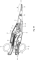
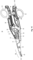
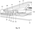
- knife deployment mechanism 150 may be actuated, as detailed above, to advance pivot pin 163 distally through slot 115e to move knife 140 from the retracted position towards the extended position to cut tissue grasped between jaw members 210, 220 (e.g., subsequent to completion of sealing the grasped tissue).
- shafts 110, 120 may be moved apart from one another, as detailed above, to the spaced-apart position illustrated in Fig. 1D such that cantilever arm 174 is resiliently returned to its at-rest position to reset knife lockout 170 to prevent movement of knife 140 from the retracted position towards the extended position.
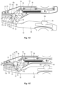
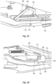
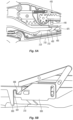
- Cantilever arm 174 in use functions as follows: when the shaft members 110, 120 are disposed in an open position, e.g., the jaw members 210, 220 are disposed in an open position, the blade 140 is prevented from being actuated as described above with respect to FIG. 1D . Upon initial closure of the shaft members 110, 120, the blade 140 may be actuated as described above with reference to FIG. 1E . Upon full actuation of the shaft members 110, 120, the blade is once against prevented from being actuated as described above with respect to FIG. 1F .
- knife return spring 3115 connects to crank link 3180 proximate link 3160 and moves concurrently therewith upon actuation of trigger 2150.
- the other end 3115b of spring 3115 is secured to shaft 3110.
- Fig. 3B shows another embodiment of the knife deployment mechanism 3150 for use with forceps 2000 which includes a trigger carrier 3300 that operably connects to the trigger 2150.
- Trigger carrier 3300 includes a cam slot 3310 defined therein that resides in general perpendicular registration with slot 3140 in knife carrier 3114 and that is configured to slidingly receive pivot 3185 therein.
- trigger carrier 3300 Upon actuation of the trigger 2150, trigger carrier 3300 is moved proximally and the pivot 3185 rides along the cam slot 3310 in a general perpendicular direction. Utilizing the cam slot 3310 allows for smoother and more consistent actuation of trigger 2150.
- Fig. 3C shows another embodiment of the knife deployment mechanism 3150 for use with forceps 2000 which includes a guide slot 3163 defined within a proximal end of link 3160 that allows pivot 3175 to ride therein during actuation of trigger 2150.
- link 3170 is moved proximally to pivot link crank 3180 distally which, in turn, forces link 3160 distally to advance knife (not shown).
- Utilizing the guide slot 3163 allows for smoother and more consistent actuation of the trigger 2150 and knife through their range of motion.
- trigger carrier 6300 As the trigger carrier 6300 is actuated (proximally), the kickout 6310 rides within slot 2123 of shaft 2120 into abutment with kickout ramp 2121. Typically, upon release of the trigger 2150, trigger carrier 6300 is supposed to automatically return to a distal-most position under the bias of knife return spring 6315. If the knife (not shown) gets caught in the knife channel disposed between jaw members 2210, 2220 or gets caught on tissue, the bias of the knife return spring 6315 may not be enough and the knife may remain in a deployed position.
- the user simply begins to open the forceps 2000 causing the shafts 2110, 2120 to move relative to one another and causing the kickout ramp 2121 to essentially "kick" the knife kickout 6310 forward as the handles 2118, 2128 open. Forward motion of the knife kickout 6310, in turn, forces the trigger carrier 6300 forward and, thus, forces the knife proximally.
- trigger carrier 7300 As the trigger carrier 7300 is actuated (proximally), the kickout 7310 rides within slot 2123 of shaft 2120 into abutment with kickout ramp 2121. Typically, upon release of the trigger 2150, trigger carrier 7300 is supposed to automatically return to a distal-most position under the bias of knife return spring 7315. If the knife (not shown) gets caught in the knife channel disposed between jaw members 2210, 2220 or gets caught on tissue, the bias of the knife return spring 7315 may not be enough and the knife may remain in a deployed position.
- kickout link 8300 As mentioned above with respect to Fig. 3A , as the trigger 2150 is actuated, kickout link 8300 is actuated (proximally), the kickout 8310 rides within slot 2123 of shaft 2120 into abutment with kickout ramp 2121. Typically, upon release of the trigger 2150, kickout link 8300 is supposed to automatically return to a distal-most position under the bias of knife return spring 8315. If the knife (not shown) gets caught in the knife channel disposed between jaw members 2210, 2220 or gets caught on tissue, the bias of the knife return spring 8315 may not be enough and the knife may remain in a deployed position.
- the user simply begins to open the forceps 2000 causing the shafts 2110, 2120 to move relative to one another and causing the kickout ramp 2121 to essentially "kick" the knife kickout 8310 and link 8180 forward as the handles 2118, 2128 open. Forward motion of the knife kickout 8310, in turn, forces the kickout link 8300 and link 8180 forward and, thus, forces the knife proximally.
- the locking pin 3165 is seated within slot 10110 preventing movement of the knife deployment mechanism 3150.
- the distal end 10105 of flange 10100 abuts shaft 2120 forcing the flange 10100 towards shaft 2110 and causing the elongated shaft 10050 to flex about sleeve 10175.
- locking pin 3165 is unseated or disengaged from slot 10110 allowing actuation of the knife deployment mechanism 3150.
- Locking pin 3165 rides along elongated slot 3375 during actuation.
- Flange 11100 includes a boss 11110 disposed thereon therein configured to seat within a gear slot 4171 defined in gear rack 4170 to prevent actuation of the knife deployment mechanism 4150 when the shaft members 2110, 2120 are disposed in an open position.
- boss 11110 is seated within gear slot 4171 preventing movement of the knife deployment mechanism 4150.
- the distal end 11105 of flange 11100 abuts shaft 2120 forcing the flange 11100 towards shaft 2110 and causing the elongated shaft 11050 to rotate about flange pin 11175.
- boss 11110 is unseated or disengaged from gear slot 4171 allowing actuation of the knife deployment mechanism 4150.
- Boss 11110 remains out of the way during movement of the opposing racks 4170, 4160 ( Fig. 4A ).
- the robotic surgical systems may be employed with one or more consoles that are next to the operating theater or located in a remote location.
- one team of surgeons or nurses may prep the patient for surgery and configure the robotic surgical system with one or more of the instruments disclosed herein while another surgeon (or group of surgeons) remotely controls the instruments via the robotic surgical system.
- a highly skilled surgeon may perform multiple operations in multiple locations without leaving his/her remote console which can be both economically advantageous and a benefit to the patient or a series of patients.
- the master handles may include various sensors to provide feedback to the surgeon relating to various tissue parameters or conditions, e.g., tissue resistance due to manipulation, cutting or otherwise treating, pressure by the instrument onto the tissue, tissue temperature, tissue impedance, etc. As can be appreciated, such sensors provide the surgeon with enhanced tactile feedback simulating actual operating conditions.
- the master handles may also include a variety of different actuators for delicate tissue manipulation or treatment further enhancing the surgeon's ability to mimic actual operating conditions.
Landscapes
- Health & Medical Sciences (AREA)
- Surgery (AREA)
- Engineering & Computer Science (AREA)
- Life Sciences & Earth Sciences (AREA)
- Biomedical Technology (AREA)
- Otolaryngology (AREA)
- Nuclear Medicine, Radiotherapy & Molecular Imaging (AREA)
- Plasma & Fusion (AREA)
- Physics & Mathematics (AREA)
- Heart & Thoracic Surgery (AREA)
- Medical Informatics (AREA)
- Molecular Biology (AREA)
- Animal Behavior & Ethology (AREA)
- General Health & Medical Sciences (AREA)
- Public Health (AREA)
- Veterinary Medicine (AREA)
- Surgical Instruments (AREA)
Applications Claiming Priority (3)
| Application Number | Priority Date | Filing Date | Title |
|---|---|---|---|
| US202062990277P | 2020-03-16 | 2020-03-16 | |
| US202117898892A | 2021-03-02 | 2021-03-02 | |
| EP21162507.4A EP3881787B1 (de) | 2020-03-16 | 2021-03-15 | Zange mit linearem auslösemechanismus |
Related Parent Applications (1)
| Application Number | Title | Priority Date | Filing Date |
|---|---|---|---|
| EP21162507.4A Division EP3881787B1 (de) | 2020-03-16 | 2021-03-15 | Zange mit linearem auslösemechanismus |
Publications (2)
| Publication Number | Publication Date |
|---|---|
| EP4578411A2 true EP4578411A2 (de) | 2025-07-02 |
| EP4578411A3 EP4578411A3 (de) | 2025-09-10 |
Family
ID=74874670
Family Applications (2)
| Application Number | Title | Priority Date | Filing Date |
|---|---|---|---|
| EP25176013.8A Pending EP4578411A3 (de) | 2020-03-16 | 2021-03-15 | Zange mit linearem auslösemechanismus |
| EP21162507.4A Active EP3881787B1 (de) | 2020-03-16 | 2021-03-15 | Zange mit linearem auslösemechanismus |
Family Applications After (1)
| Application Number | Title | Priority Date | Filing Date |
|---|---|---|---|
| EP21162507.4A Active EP3881787B1 (de) | 2020-03-16 | 2021-03-15 | Zange mit linearem auslösemechanismus |
Country Status (1)
| Country | Link |
|---|---|
| EP (2) | EP4578411A3 (de) |
Family Cites Families (3)
| Publication number | Priority date | Publication date | Assignee | Title |
|---|---|---|---|---|
| US7131970B2 (en) * | 2003-11-19 | 2006-11-07 | Sherwood Services Ag | Open vessel sealing instrument with cutting mechanism |
| US10653475B2 (en) * | 2017-06-08 | 2020-05-19 | Covidien Lp | Knife lockout for electrosurgical forceps |
| US11020169B2 (en) * | 2018-05-25 | 2021-06-01 | Cilag Gmbh International | Method and apparatus for open electrosurgical shears |
-
2021
- 2021-03-15 EP EP25176013.8A patent/EP4578411A3/de active Pending
- 2021-03-15 EP EP21162507.4A patent/EP3881787B1/de active Active
Also Published As
| Publication number | Publication date |
|---|---|
| EP3881787A1 (de) | 2021-09-22 |
| EP4578411A3 (de) | 2025-09-10 |
| EP3881787B1 (de) | 2025-05-14 |
Similar Documents
| Publication | Publication Date | Title |
|---|---|---|
| US20250359920A1 (en) | Forceps with linear trigger mechanism | |
| US12127784B2 (en) | Electrosurgical forceps for grasping, treating, and/or dividing tissue | |
| CN206482658U (zh) | 外科手术器械和外科手术钳 | |
| EP1815809B1 (de) | Griff für chirurgische Instrumente | |
| US12539164B2 (en) | Knife lockout for electrosurgical forceps | |
| EP3020351B1 (de) | Einsatzmechanismus für chirurgische instrumente | |
| US20210121189A1 (en) | Articulation assemblies for use with endoscopic surgical instruments | |
| US20180049752A1 (en) | Surgical forceps | |
| US11510725B2 (en) | Electrosurgical forceps | |
| EP3881787B1 (de) | Zange mit linearem auslösemechanismus | |
| EP3005968B1 (de) | Einsatzmechanismus für chirurgische instrumente | |
| US11419665B2 (en) | Electrosurgical forceps | |
| EP3753503A1 (de) | Chirurgische instrumente zur durchführung von tonsillektomie, adenotomie und anderen chirurgischen eingriffen | |
| US12611216B2 (en) | Partial clip closure mechanisms for surgical clip appliers and surgical clip appliers incorporating the same | |
| US20260123983A1 (en) | Actuation mechanisms for surgical instruments and surgical instruments incorporating the same | |
| US11304743B2 (en) | Electrosurgical forceps | |
| EP3799817A1 (de) | Chirurgische instrumente zur durchführung von tonsillektomie, adenotomie und anderen chirurgischen eingriffen | |
| WO2025008738A1 (en) | Actuation mechanisms for surgical instruments and surgical instruments incorporating the same |
Legal Events
| Date | Code | Title | Description |
|---|---|---|---|
| PUAI | Public reference made under article 153(3) epc to a published international application that has entered the european phase |
Free format text: ORIGINAL CODE: 0009012 |
|
| STAA | Information on the status of an ep patent application or granted ep patent |
Free format text: STATUS: REQUEST FOR EXAMINATION WAS MADE |
|
| 17P | Request for examination filed |
Effective date: 20250513 |
|
| AC | Divisional application: reference to earlier application |
Ref document number: 3881787 Country of ref document: EP Kind code of ref document: P |
|
| AK | Designated contracting states |
Kind code of ref document: A2 Designated state(s): AL AT BE BG CH CY CZ DE DK EE ES FI FR GB GR HR HU IE IS IT LI LT LU LV MC MK MT NL NO PL PT RO RS SE SI SK SM TR |
|
| REG | Reference to a national code |
Ref country code: DE Ref legal event code: R079 Free format text: PREVIOUS MAIN CLASS: A61B0018000000 Ipc: A61B0018140000 |
|
| PUAL | Search report despatched |
Free format text: ORIGINAL CODE: 0009013 |
|
| AK | Designated contracting states |
Kind code of ref document: A3 Designated state(s): AL AT BE BG CH CY CZ DE DK EE ES FI FR GB GR HR HU IE IS IT LI LT LU LV MC MK MT NL NO PL PT RO RS SE SI SK SM TR |
|
| RIC1 | Information provided on ipc code assigned before grant |
Ipc: A61B 18/14 20060101AFI20250806BHEP Ipc: A61B 18/00 20060101ALN20250806BHEP |