EP4578381A2 - Intravascular imaging procedure-specific workflow guidance and associated devices, systems, and methods - Google Patents
Intravascular imaging procedure-specific workflow guidance and associated devices, systems, and methods Download PDFInfo
- Publication number
- EP4578381A2 EP4578381A2 EP25170272.6A EP25170272A EP4578381A2 EP 4578381 A2 EP4578381 A2 EP 4578381A2 EP 25170272 A EP25170272 A EP 25170272A EP 4578381 A2 EP4578381 A2 EP 4578381A2
- Authority
- EP
- European Patent Office
- Prior art keywords
- vessel
- stent
- display
- area
- interest
- Prior art date
- Legal status (The legal status is an assumption and is not a legal conclusion. Google has not performed a legal analysis and makes no representation as to the accuracy of the status listed.)
- Pending
Links
Images





Classifications
-
- A—HUMAN NECESSITIES
- A61—MEDICAL OR VETERINARY SCIENCE; HYGIENE
- A61B—DIAGNOSIS; SURGERY; IDENTIFICATION
- A61B5/00—Measuring for diagnostic purposes; Identification of persons
- A61B5/0059—Measuring for diagnostic purposes; Identification of persons using light, e.g. diagnosis by transillumination, diascopy, fluorescence
- A61B5/0082—Measuring for diagnostic purposes; Identification of persons using light, e.g. diagnosis by transillumination, diascopy, fluorescence adapted for particular medical purposes
- A61B5/0084—Measuring for diagnostic purposes; Identification of persons using light, e.g. diagnosis by transillumination, diascopy, fluorescence adapted for particular medical purposes for introduction into the body, e.g. by catheters
-
- A—HUMAN NECESSITIES
- A61—MEDICAL OR VETERINARY SCIENCE; HYGIENE
- A61B—DIAGNOSIS; SURGERY; IDENTIFICATION
- A61B5/00—Measuring for diagnostic purposes; Identification of persons
- A61B5/02—Detecting, measuring or recording for evaluating the cardiovascular system, e.g. pulse, heart rate, blood pressure or blood flow
- A61B5/02007—Evaluating blood vessel condition, e.g. elasticity, compliance
-
- A—HUMAN NECESSITIES
- A61—MEDICAL OR VETERINARY SCIENCE; HYGIENE
- A61B—DIAGNOSIS; SURGERY; IDENTIFICATION
- A61B5/00—Measuring for diagnostic purposes; Identification of persons
- A61B5/103—Measuring devices for testing the shape, pattern, colour, size or movement of the body or parts thereof, for diagnostic purposes
- A61B5/107—Measuring physical dimensions, e.g. size of the entire body or parts thereof
- A61B5/1076—Measuring physical dimensions, e.g. size of the entire body or parts thereof for measuring dimensions inside body cavities, e.g. using catheters
-
- A—HUMAN NECESSITIES
- A61—MEDICAL OR VETERINARY SCIENCE; HYGIENE
- A61B—DIAGNOSIS; SURGERY; IDENTIFICATION
- A61B5/00—Measuring for diagnostic purposes; Identification of persons
- A61B5/103—Measuring devices for testing the shape, pattern, colour, size or movement of the body or parts thereof, for diagnostic purposes
- A61B5/107—Measuring physical dimensions, e.g. size of the entire body or parts thereof
- A61B5/1079—Measuring physical dimensions, e.g. size of the entire body or parts thereof using optical or photographic means
-
- A—HUMAN NECESSITIES
- A61—MEDICAL OR VETERINARY SCIENCE; HYGIENE
- A61B—DIAGNOSIS; SURGERY; IDENTIFICATION
- A61B5/00—Measuring for diagnostic purposes; Identification of persons
- A61B5/68—Arrangements of detecting, measuring or recording means, e.g. sensors, in relation to patient
- A61B5/6846—Arrangements of detecting, measuring or recording means, e.g. sensors, in relation to patient specially adapted to be brought in contact with an internal body part, i.e. invasive
- A61B5/6847—Arrangements of detecting, measuring or recording means, e.g. sensors, in relation to patient specially adapted to be brought in contact with an internal body part, i.e. invasive mounted on an invasive device
- A61B5/6852—Catheters
-
- A—HUMAN NECESSITIES
- A61—MEDICAL OR VETERINARY SCIENCE; HYGIENE
- A61B—DIAGNOSIS; SURGERY; IDENTIFICATION
- A61B5/00—Measuring for diagnostic purposes; Identification of persons
- A61B5/74—Details of notification to user or communication with user or patient; User input means
- A61B5/742—Details of notification to user or communication with user or patient; User input means using visual displays
- A61B5/743—Displaying an image simultaneously with additional graphical information, e.g. symbols, charts, function plots
-
- A—HUMAN NECESSITIES
- A61—MEDICAL OR VETERINARY SCIENCE; HYGIENE
- A61B—DIAGNOSIS; SURGERY; IDENTIFICATION
- A61B8/00—Diagnosis using ultrasonic, sonic or infrasonic waves
- A61B8/08—Clinical applications
- A61B8/0891—Clinical applications for diagnosis of blood vessels
-
- A—HUMAN NECESSITIES
- A61—MEDICAL OR VETERINARY SCIENCE; HYGIENE
- A61B—DIAGNOSIS; SURGERY; IDENTIFICATION
- A61B8/00—Diagnosis using ultrasonic, sonic or infrasonic waves
- A61B8/12—Diagnosis using ultrasonic, sonic or infrasonic waves in body cavities or body tracts, e.g. by using catheters
-
- A—HUMAN NECESSITIES
- A61—MEDICAL OR VETERINARY SCIENCE; HYGIENE
- A61B—DIAGNOSIS; SURGERY; IDENTIFICATION
- A61B8/00—Diagnosis using ultrasonic, sonic or infrasonic waves
- A61B8/46—Ultrasonic, sonic or infrasonic diagnostic devices with special arrangements for interfacing with the operator or the patient
-
- A—HUMAN NECESSITIES
- A61—MEDICAL OR VETERINARY SCIENCE; HYGIENE
- A61B—DIAGNOSIS; SURGERY; IDENTIFICATION
- A61B8/00—Diagnosis using ultrasonic, sonic or infrasonic waves
- A61B8/46—Ultrasonic, sonic or infrasonic diagnostic devices with special arrangements for interfacing with the operator or the patient
- A61B8/467—Ultrasonic, sonic or infrasonic diagnostic devices with special arrangements for interfacing with the operator or the patient characterised by special input means
- A61B8/469—Ultrasonic, sonic or infrasonic diagnostic devices with special arrangements for interfacing with the operator or the patient characterised by special input means for selection of a region of interest
Definitions
- the present disclosure relates generally to obtaining intravascular data associated with a body vessel of a patient, and, in particular, to providing a workflow to a user to perform an intravascular imaging procedure with an intravascular imaging device.
- the workflow may be displayed to a user as prompts and instructions as well as visualizations of imaging data from the intravascular imaging device.
- IVUS imaging is widely used in interventional cardiology as a diagnostic tool for assessing a diseased vessel, such as an artery, within the human body to determine the need for treatment, to guide the intervention, and/or to assess its effectiveness.
- An IVUS device including one or more ultrasound transducers is passed into the vessel and guided to the area to be imaged. The transducers emit ultrasonic energy and receive ultrasound echoes reflected from the vessel. The ultrasound echoes are processed to create an image of the vessel of interest.
- intravascular imaging systems typically require operators to have a high degree of skill and experience to safely operate intravascular devices.
- the performance of an intravascular procedure may include many steps including maneuvering devices, measurements, and analysis of results. An operator must know and complete all of these steps to successfully perform the procedure. The large number and complexity of steps may make these procedures difficult to perform and may cause errors in the procedures.
- the intravascular imaging system may include a controller configured to provide a selectable options on a display device to select a target vessel, identify an area of interest within the selected target vessel based on the received imaging data, and automatically display, in response to identifying the area of interest, vessel measurements corresponding with the area of interest on the display device.
- Embodiments of the present disclosure provide an intravascular imaging system, which may include: a controller in communication with an intravascular imaging device, the controller configured to: provide, on a display device in communication with the controller, a selectable option to select a target vessel; provide a prompt to move the intravascular imaging device within the selected target vessel; receive imaging data from an imaging sensor during movement of the intravascular imaging device within the selected target vessel; identify an area of interest within the selected target vessel based on the received imaging data; and automatically display, in response to identifying the area of interest, vessel measurements corresponding with the area of interest on the display device.
- the intravascular imaging system further includes the intravascular imaging device, including: a flexible elongate member configured to be inserted into the target vessel of a patient; the imaging sensor disposed on a distal portion of the flexible elongate member; and the display device.
- the controller may be further configured to provide a selectable option on the display device to perform a pre-stent procedure or a post-stent check.
- the controller may be further configured to automatically measure a diameter of the vessel within the area of interest, determine a first location within the area of interest with a minimum diameter, and display the first location and the minimum diameter on the display device.
Landscapes
- Health & Medical Sciences (AREA)
- Life Sciences & Earth Sciences (AREA)
- General Health & Medical Sciences (AREA)
- Public Health (AREA)
- Pathology (AREA)
- Engineering & Computer Science (AREA)
- Biomedical Technology (AREA)
- Heart & Thoracic Surgery (AREA)
- Medical Informatics (AREA)
- Molecular Biology (AREA)
- Surgery (AREA)
- Veterinary Medicine (AREA)
- Biophysics (AREA)
- Physics & Mathematics (AREA)
- Animal Behavior & Ethology (AREA)
- Nuclear Medicine, Radiotherapy & Molecular Imaging (AREA)
- Radiology & Medical Imaging (AREA)
- Dentistry (AREA)
- Oral & Maxillofacial Surgery (AREA)
- Vascular Medicine (AREA)
- Cardiology (AREA)
- Physiology (AREA)
- Ultra Sonic Daignosis Equipment (AREA)
- Endoscopes (AREA)
Abstract
Description
- The present disclosure relates generally to obtaining intravascular data associated with a body vessel of a patient, and, in particular, to providing a workflow to a user to perform an intravascular imaging procedure with an intravascular imaging device. The workflow may be displayed to a user as prompts and instructions as well as visualizations of imaging data from the intravascular imaging device.
- Various types of intravascular imaging systems are used in diagnosing and treating diseases. For example, intravascular ultrasound (IVUS) imaging is widely used in interventional cardiology as a diagnostic tool for assessing a diseased vessel, such as an artery, within the human body to determine the need for treatment, to guide the intervention, and/or to assess its effectiveness. An IVUS device including one or more ultrasound transducers is passed into the vessel and guided to the area to be imaged. The transducers emit ultrasonic energy and receive ultrasound echoes reflected from the vessel. The ultrasound echoes are processed to create an image of the vessel of interest.
- The advent of faster computational analysis has increased the effectiveness of intravascular imaging systems. However, existing intravascular imaging systems typically require operators to have a high degree of skill and experience to safely operate intravascular devices. For example, depending on the type of operation, the performance of an intravascular procedure may include many steps including maneuvering devices, measurements, and analysis of results. An operator must know and complete all of these steps to successfully perform the procedure. The large number and complexity of steps may make these procedures difficult to perform and may cause errors in the procedures.
- Systems, devices, and methods for providing instructions for an operator of an intravascular imaging system are provided. The intravascular imaging system may include a controller configured to provide a selectable options on a display device to select a target vessel, identify an area of interest within the selected target vessel based on the received imaging data, and automatically display, in response to identifying the area of interest, vessel measurements corresponding with the area of interest on the display device. Aspects of the present disclosure advantageously provide complete end-to-end workflow solutions that overcome the limitations of existing intravascular imaging systems.
- Embodiments of the present disclosure provide an intravascular imaging system, which may include: a controller in communication with an intravascular imaging device, the controller configured to: provide, on a display device in communication with the controller, a selectable option to select a target vessel; provide a prompt to move the intravascular imaging device within the selected target vessel; receive imaging data from an imaging sensor during movement of the intravascular imaging device within the selected target vessel; identify an area of interest within the selected target vessel based on the received imaging data; and automatically display, in response to identifying the area of interest, vessel measurements corresponding with the area of interest on the display device.
- In embodiments, the intravascular imaging system further includes the intravascular imaging device, including: a flexible elongate member configured to be inserted into the target vessel of a patient; the imaging sensor disposed on a distal portion of the flexible elongate member; and the display device. The controller may be further configured to provide a selectable option on the display device to perform a pre-stent procedure or a post-stent check. The controller may be further configured to automatically measure a diameter of the vessel within the area of interest, determine a first location within the area of interest with a minimum diameter, and display the first location and the minimum diameter on the display device.
- In some embodiments, the display of the vessel measurements is configured to allow a user to edit a depiction of a border of the vessel. The display of the vessel measurements may include a first view and a second view of the area of interest different from the first view. A user's edit to the depiction of the border of the vessel may be displayed in the first view and the second view of the area of interest. The display of the vessel measurements may include a depiction of a target area for a stent if a user selects the pre-stent procedure option. The display of the vessel measurements may include a depiction of a stent if a user selects the post-stent check option. The display of the vessel measurements may further include a depiction of a stent malapposition.
- A method of intravascular imaging is also provided, which may include: providing, with a controller in communication with an intravascular imaging device, a selectable option on a display device to select a target vessel within a patient; providing, with the controller, a prompt to move the intravascular imaging device in the selected target vessel on the display device; receiving, with the controller, imaging data from an imaging sensor while the intravascular imaging device is moved within the selected target vessel; identifying, with the controller, an area of interest within the selected target vessel based on the received imaging data; and displaying automatically, with the display device, vessel measurements corresponding with the area of interest.
- The method may also include providing, with a controller, a selectable option on a display device to perform a pre-stent procedure or a post-stent check. The method may include measuring, with the controller, a diameter of the vessel within the area of interest, identifying a first location with a minimum diameter within the area of interest; and displaying the first location and minimum diameter on the display device. The method may include providing, with the controller, an option to edit a depiction of a border of the vessel on the display device.
- In some embodiments, the display of the vessel measurements includes a first view and a second view of the area of interest different from the first view. The method may include displaying an edit to the depiction of the border of the vessel in the first view and the second view of the area of interest. The method may include displaying the edit to the depiction of the border of the vessel in a third view different from the first view and the second view. The display of the vessel measurements may include a depiction of a target area for a stent if a user selects the pre-stent procedure option. The display of the vessel measurements may include a depiction of a stent if a user selects the post-stent check option. The display of the vessel measurements further may include a depiction of a stent malapposition.
- Additional aspects, features, and advantages of the present disclosure will become apparent from the following detailed description.
- Illustrative embodiments of the present disclosure will be described with reference to the accompanying drawings, of which:
-
Fig. 1 is a diagrammatic schematic view of an intravascular imaging system, according to aspects of the present disclosure. -
Fig. 2 is an exemplary illustration of a display showing a prompt according to aspects of the present disclosure. -
Fig. 3 is an exemplary illustration of a display showing another prompt according to aspects of the present disclosure. -
Fig. 4 is an exemplary illustration of a display showing another prompt and instructions according to aspects of the present disclosure. -
Fig. 5 is an exemplary illustration of a display showing imaging data and instructions according to aspects of the present disclosure. -
Fig. 6 is an exemplary illustration of a display showing imaging data according to aspects of the present disclosure. -
Fig. 7A is an exemplary illustration of a display showing various views of imaging data according to aspects of the present disclosure. -
Fig. 7B is an exemplary illustration of another display showing various views of imaging data according to aspects of the present disclosure. -
Fig. 7C is an exemplary illustration of another display showing various views of imaging data according to aspects of the present disclosure. -
Fig. 8 is an exemplary illustration of a display showing imaging data according to aspects of the present disclosure. -
Fig. 9 is an exemplary illustration of a display showing imaging data according to aspects of the present disclosure. -
Fig. 10 is a flow diagram of a method of providing a guided workflow according to aspects of the present disclosure. - For the purposes of promoting an understanding of the principles of the present disclosure, reference will now be made to the embodiments illustrated in the drawings, and specific language will be used to describe the same. It is nevertheless understood that no limitation to the scope of the disclosure is intended. Any alterations and further modifications to the described devices, systems, and methods, and any further application of the principles of the present disclosure are fully contemplated and included within the present disclosure as would normally occur to one skilled in the art to which the disclosure relates. In particular, it is fully contemplated that the features, components, and/or steps described with respect to one embodiment may be combined with the features, components, and/or steps described with respect to other embodiments of the present disclosure. For the sake of brevity, however, the numerous iterations of these combinations will not be described separately.
-
Fig. 1 is a diagrammatic schematic view of anintravascular imaging system 100, according to aspects of the present disclosure. Theintravascular imaging system 100 may include anintravascular device 102, a patient interface module (PIM) 104, a console orprocessing system 106, and a display device ormonitor 108. Theintravascular device 102 may be sized and shaped, and/or otherwise structurally arranged or configured to be positioned within abody lumen 120 of a patient. For example, theintravascular device 102 can be a catheter, guide wire, guide catheter, pressure wire, and/or flow wire in various embodiments. In some circumstances, thesystem 100 may include additional elements and/or may be implemented without one or more of the elements illustrated inFig. 1 . - The devices, systems, and methods described herein can include one or more features described in U.S. Provisional App. No. _______ (Attorney Docket No. 2017PF02102), filed on an even date herewith, U.S. Provisional App. No. ________ (Attorney Docket No. 2017PF02103), filed on an even date herewith, U.S. Provisional App. No. _______ (Attorney Docket No. 2017PF02101), filed on an even date herewith, and U.S. Provisional App. No. (Attorney Docket No. 2017PF02365), filed on an even date herewith, each of which is hereby incorporated by reference in its entirety.
- The intravascular imaging system 100 (or intraluminal imaging system) can be any type of imaging system suitable for use in the lumens or vasculature of a patient. In some embodiments, the
intravascular imaging system 100 is an intravascular ultrasound (IVUS) imaging system. In other embodiments, theintravascular imaging system 100 may include systems configured for forward looking intravascular ultrasound (FL-IVUS) imaging, intravascular photoacoustic (IVPA) imaging, intracardiac echocardiography (ICE), transesophageal echocardiography (TEE), and/or other suitable imaging modalities. - It is understood that the
system 100 and/ordevice 102 can be configured to obtain any suitable intravascular imaging data. In some embodiments, thedevice 102 can include an imaging component of any suitable imaging modality, such as optical imaging, optical coherence tomography (OCT), etc. In some embodiments, thedevice 102 can include any suitable imaging component, including a pressure sensor, a flow sensor, a temperature sensor, an optical fiber, a reflector, a mirror, a prism, an ablation element, a radio frequency (RF) electrode, a conductor, and/or combinations thereof. Generally, thedevice 102 can include a imaging element to obtain intravascular data associated with thelumen 120. Thedevice 102 may be sized and shaped (and/or configured) for insertion into a vessel orlumen 120 of the patient. - The
system 100 may be deployed in a catheterization laboratory having a control room. Theprocessing system 106 may be located in the control room. Optionally, theprocessing system 106 may be located elsewhere, such as in the catheterization laboratory itself. The catheterization laboratory may include a sterile field while its associated control room may or may not be sterile depending on the procedure to be performed and/or on the health care facility. The catheterization laboratory and control room may be used to perform any number of medical imaging procedures such as angiography, fluoroscopy, CT, IVUS, virtual histology (VH), forward looking IVUS (FL-IVUS), intravascular photoacoustic (IVPA) imaging, a fractional flow reserve (FFR) determination, a coronary flow reserve (CFR) determination, optical coherence tomography (OCT), computed tomography, intracardiac echocardiography (ICE), forward-looking ICE (FLICE), intravascular palpography, transesophageal ultrasound, fluoroscopy, and other medical imaging modalities, or combinations thereof. In some embodiments,device 102 may be controlled from a remote location such as the control room, such than an operator is not required to be in close proximity to the patient. - The
intravascular device 102,PIM 104, and monitor 108 may be communicatively coupled directly or indirectly to theprocessing system 106. These elements may be communicatively coupled to themedical processing system 106 via a wired connection such as a standard copper link or a fiber optic link and/or via wireless connections using IEEE 802.11 Wi-Fi standards, Ultra Wide-Band (UWB) standards, wireless FireWire, wireless USB, or another high-speed wireless networking standard. Theprocessing system 106 may be communicatively coupled to one or more data networks, e.g., a TCP/IP-based local area network (LAN). In other embodiments, different protocols may be utilized such as Synchronous Optical Networking (SONET). In some cases, theprocessing system 106 may be communicatively coupled to a wide area network (WAN). Theprocessing system 106 may utilize network connectivity to access various resources. For example, theprocessing system 106 may communicate with a Digital Imaging and Communications in Medicine (DICOM) system, a Picture Archiving and Communication System (PACS), and/or a Hospital Information System via a network connection. - At a high level, the
intravascular device 102 emits ultrasonic energy from atransducer array 124 included inscanner assembly 110 mounted near a distal end of theintravascular device 102. The ultrasonic energy is reflected by tissue structures in the medium (such as a lumen 120) surrounding thescanner assembly 110, and the ultrasound echo signals are received by thetransducer array 124. Thescanner assembly 110 generates electrical signal(s) representative of the ultrasound echoes. Thescanner assembly 110 can include one or more single ultrasound transducers and/or atransducer array 124 in any suitable configuration, such as a planar array, a curved array, a circumferential array, an annular array, etc. For example, thescanner assembly 110 can be a one-dimensional array or a two-dimensional array in some instances. In some instances, thescanner assembly 110 can be a rotational ultrasound device. The active area of thescanner assembly 110 can include one or more transducer materials and/or one or more segments of ultrasound elements (e.g., one or more rows, one or more columns, and/or one or more orientations) that can be uniformly or independently controlled and activated. The active area of thescanner assembly 110 can be patterned or structured in various basic or complex geometries. Thescanner assembly 110 can be disposed in a side-looking orientation (e.g., ultrasonic energy emitted perpendicular and/or orthogonal to the longitudinal axis of the intravascular device 102) and/or a forward-looking looking orientation (e.g., ultrasonic energy emitted parallel to and/or along the longitudinal axis). In some instances, thescanner assembly 110 is structurally arranged to emit and/or receive ultrasonic energy at an oblique angle relative to the longitudinal axis, in a proximal or distal direction. In some embodiments, ultrasonic energy emission can be electronically steered by selective triggering of one or more transducer elements of thescanner assembly 110. - The ultrasound transducer(s) of the
scanner assembly 110 can be a piezoelectric micromachined ultrasound transducer (PMUT), capacitive micromachined ultrasonic transducer (CMUT), single crystal, lead zirconate titanate (PZT), PZT composite, other suitable transducer type, and/or combinations thereof. In an embodiment theultrasound transducer array 124 can include any suitable number of individual transducers between 1 transducer and 1000 transducers, including values such as 2 transducers, 4 transducers, 36 transducers, 64 transducers, 128 transducers, 500 transducers, 812 transducers, and/or other values both larger and smaller. - The
PIM 104 transfers the received echo signals to theprocessing system 106 where the ultrasound image (including the flow information) is reconstructed and displayed on themonitor 108. The console orprocessing system 106 can include a processor and a memory. Theprocessing system 106 may be operable to facilitate the features of theintravascular imaging system 100 described herein. For example, the processor can execute computer readable instructions stored on the non-transitory tangible computer readable medium. - The
PIM 104 facilitates communication of signals between theprocessing system 106 and thescanner assembly 110 included in theintravascular device 102. This communication may include providing commands to integrated circuit controller chip(s) within theintravascular device 102, select particular element(s) on thetransducer array 124 to be used for transmit and receive, providing the transmit trigger signals to the integrated circuit controller chip(s) to activate the transmitter circuitry to generate an electrical pulse to excite the selected transducer array element(s), and/or accepting amplified echo signals received from the selected transducer array element(s) via amplifiers included on the integrated circuit controller chip(s). In some embodiments, thePIM 104 performs preliminary processing of the echo data prior to relaying the data to theprocessing system 106. In examples of such embodiments, thePIM 104 performs amplification, filtering, and/or aggregating of the data. In an embodiment, thePIM 104 also supplies high- and low-voltage DC power to support operation of theintravascular device 102 including circuitry within thescanner assembly 110. - The
processing system 106 receives echo data from thescanner assembly 110 by way of thePIM 104 and processes the data to reconstruct an image of the tissue structures in the medium surrounding thescanner assembly 110. Generally, thedevice 102 can be utilized within any suitable anatomy and/or body lumen of the patient. Theprocessing system 106 outputs image data such that an image of the vessel orlumen 120, such as a cross-sectional IVUS image of thelumen 120, is displayed on themonitor 108.Lumen 120 may represent fluid filled or surrounded structures, both natural and man-made.Lumen 120 may be within a body of a patient.Lumen 120 may be a blood vessel, as an artery or a vein of a patient's vascular system, including cardiac vasculature, peripheral vasculature, neural vasculature, renal vasculature, and/or or any other suitable lumen inside the body. For example, thedevice 102 may be used to examine any number of anatomical locations and tissue types, including without limitation, organs including the liver, heart, kidneys, gall bladder, pancreas, lungs; ducts; intestines; nervous system structures including the brain, dural sac, spinal cord and peripheral nerves; the urinary tract; as well as valves within the blood, chambers or other parts of the heart, and/or other systems of the body. In addition to natural structures, thedevice 102 may be used to examine man-made structures such as, but without limitation, heart valves, stents, shunts, filters and other devices. - The processing system or
controller 106 may include a processing circuit having one or more processors in communication with memory and/or other suitable tangible computer readable storage media. The processing system orcontroller 106 may be configured to carry out one or more aspects of the present disclosure. In some embodiments, theprocessing system 106 and themonitor 108 are separate components. In other embodiments, theprocessing system 106 and themonitor 108 are integrated in a single component. For example, thesystem 100 can include a touch screen device, including a housing having a touch screen display and a processor. Thesystem 100 can include any suitable input device, such as a touch sensitive pad or touch screen display, keyboard/mouse, joystick, button, etc., for a user to select options shown on themonitor 108. Theprocessing system 106, themonitor 108, the input device, and/or combinations thereof can be referenced as a controller of thesystem 100. The controller can be in communication with thedevice 102, thePIM 104, theprocessing system 106, themonitor 108, the input device, and/or other components of thesystem 100. - In some embodiments, the
intravascular device 102 includes some features similar to traditional solid-state IVUS catheters, such as the EagleEye® catheter available from Volcano Corporation and those disclosed inU.S. Patent No. 7,846,101 hereby incorporated by reference in its entirety. For example, theintravascular device 102 my include thescanner assembly 110 near a distal end of theintravascular device 102 and atransmission line bundle 112 extending along the longitudinal body of theintravascular device 102. The cable ortransmission line bundle 112 can include a plurality of conductors, including one, two, three, four, five, six, seven, or more conductors. - The
transmission line bundle 112 terminates in aPIM connector 114 at a proximal end of theintravascular device 102. ThePIM connector 114 electrically couples thetransmission line bundle 112 to thePIM 104 and physically couples theintravascular device 102 to thePIM 104. In an embodiment, theintravascular device 102 further includes aguidewire exit port 116. Accordingly, in some instances theintravascular device 102 is a rapid-exchange catheter. Theguidewire exit port 116 allows aguidewire 118 to be inserted towards the distal end in order to direct theintravascular device 102 through thelumen 120. - The
monitor 108 may be a display device such as a computer monitor or other type of screen. Themonitor 108 may be used to display selectable prompts, instructions, and visualizations of imaging data to a user. In some embodiments, themonitor 108 may be used to provide a procedure-specific workflow to a user to complete an intravascular imaging procedure. This workflow may include performing a pre-stent plan to determine the state of a lumen and potential for a stent, as well as checking on a stent that has been positioned in a lumen. The workflow may presented to a user as any of the displays or visualizations shown inFigs. 2-9 . -
Fig. 2 shows anexemplary display 200 showing a prompt 202 according to aspects of the present disclosure. In some embodiments, thedisplay 200 is displayed on themonitor 108 as shown inFig. 1 . In other embodiments, thedisplay 200 is displayed on a screen of another device, such asPIM 104. Thedisplay 200 may be generated by a controller of theintravascular imaging system 100. In some embodiments, thedisplay 200 is configured to display prompts and instructions as well as other data to an operator. Thedisplay 200 may be used to show a complete end-to-end workflow for an intravascular procedure. This workflow may include a number of prompts and instructions that may guide an operator through a procedure. This may simplify the steps of a procedure and help to avoid operator errors. - The prompts and instructions may be displayed on the
display 200 as selectable options such that an operator may interact with thedisplay 200 to choose options. The selections of the operator may change thedisplay 200 such that information corresponding with the selected options is shown. In the example ofFig. 1 , aselectable prompt 202 is displayed ondisplay 200. The prompt includes two selectable options:option 204 corresponds to a pre-stent plan andoption 206 corresponds to a post-stent check. The operator may select one of theoptions prompt 302 as shown inFig. 3 ). Theoptions option 204 may include a depiction of vasculature within the heart andoption 206 may include a depiction of a stent. In some embodiments, the selection of anoption option pre-stent plan option 204 is selected, theoption 204 may appear as shaded or grey in future displays of thedisplay 200. This may help to indicate that thisoption 204 has previously been selected by an operator. Other types of feedback may be used to indicate selections of options. For example, theselectable options -
Option 204 may provide a workflow for a pre-stent plan that may include performing an intravascular procedure (such as a pullback operation) and viewing results.Option 204 may be used to identify areas within alumen 120 that may benefit from the placement of a stent.Option 206 may provide a workflow for a post-stent check that may include performing an intravascular procedure (such as a pullback operation) and viewing results of an area within alumen 120 where a stent has previously been placed. Thisoption 206 may be used to observe the placement and effectiveness of the stent. -
Fig. 3 shows anexemplary display 200 showing a prompt 302 according to aspects of the present disclosure. The colors, shading, textures, and other graphical properties of thedisplay 200 may be chosen to highlight specific features. In some embodiments, the prompt 302 may be displayed after either of theoptions pre-stent plan option 204 is selected. The prompt 302 may prompt the operator to select a target vessel. In the example ofFig. 3 , selecting the target vessel includes selecting a region on avisualization 304 including arteries in the heart. The selectable regions may include the right coronary artery (RCA), left anterior descending (LAD), and left circumflex artery (LCX). The selectable regions may also include various regions of the arteries, as well as other vessels and lumens within other parts of the anatomy of a patient. The appearance of thevisualization 304 may be altered when one of the regions is selected by the operator. For example, the selected artery may be outlined, highlighted, or colored with a different color. In some embodiments, the selected artery is outlined in a contrasting color (e.g., blue, red, or another color), shaded, shown with a texture, or otherwise highlighted. -
Fig. 4 shows anexemplary display 200 showing a prompt 402 according to aspects of the present disclosure. The prompt 402 may be displayed after the operator has made a selection on the prompt 302 shown inFig. 3 . In the example ofFig. 4 , the LAD artery has been selected by an operator. The prompt 402 shows the outlined image of the LAD along withinstructions 403 to perform a pullback procedure from the most distal point on the LAD to the ostium. Theseinstructions 403 may refer to a pullback procedure or other movement of thedevice 102 within the selected vessel orlumen 120. Theinstructions 403 may instruct an operator to perform any type of movement of thedevice 102 within a selected target vessel. For example, theinstructions 403 may instruct an operator to push the device 102 a given distance along the selected target vessel. Avisualization 404 corresponding to theinstructions 403 may also be displayed on thedisplay 200. In the example ofFig. 4 , thevisualization 404 includes aline 406 with arrows showing the direction in which the pullback procedure should be performed. Thevisualization 404 may include visual effects such as changing colors or animation. For example, the arrows of thevisualization 404 may move in the direction specified by theinstructions 403. Theinstructions 403 andvisualization 404 may vary depending on options that were previously selected. For example, if an operator selected the RCA as the target vessel, thevisualization 404 of the RCA would be highlighted and a corresponding visualization would be displayed showing a procedure outlined byinstructions 403. - In some embodiments, the
instructions 403 of thedisplay 200 may vary depending on whichoption Fig. 2 . For example, if thepost-stent check option 206 was selected, the instructions may read "please perform pullback from the distal point of the stent to the proximal point of the stent." Other instructions may also be included to guide the operator to perform an imaging procedure and acquire imaging data relevant to the selected target vessel and/or stent. -
Fig. 5 shows anexemplary display 200 showing a prompt 502 according to aspects of the present disclosure. The prompt 502 may be displayed after the operator has made a selection on the prompt 402 shown inFig. 4 . In the example ofFig. 5 , the LAD artery has been selected by an operator. The prompt 502 may be accompanied by avisualization 504. In some embodiments, thevisualization 504 shows imaging data from thedevice 102 as thedevice 102 is moved through the selected target vessel. The imaging data may be used as a reference for the operator. In particular, imaging data shown in thevisualization 504 may help the operator to know where to begin a procedure. In the example ofFig. 5 , the imaging data may show when thedevice 102 is positioned at a distal end of the LAD artery so that a pullback operation may be performed. The imaging data may also show other reference data such as areas of interest along alumen 120, branches of thelumen 120, problem areas within thelumen 120, or other features. In some embodiments, when thedevice 102 is placed at the location specified by the instructions (for example, at a distal portion of an artery), the operator may select therecord button 508 to begin a recording of the procedure. The display may also include anoption 506 to save specific frames of imaging data before or during a procedure. -
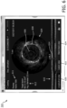
Fig. 6 shows anexemplary visualization 310 according to aspects of the present disclosure. Thevisualization 310 may be displayed on amonitor 108. Thevisualization 310 may present imaging data acquired by thedevice 102 during an intravascular procedure. In some embodiments, the intravascular procedure is outlined in the instructions shown inFigs. 3-5 . In some embodiments, thevisualization 310 includes imaging data corresponding to alumen 120, such as the selected target vessel. Thevisualization 310 may include afirst view 604 and asecond view 610 of thelumen 120. In some embodiments, the first andsecond views Fig. 6 , thefirst view 604 shows imaging data corresponding to a view straight down the lumen 120 (otherwise discussed as a "longitudinal view") and thesecond view 610 shows imaging data corresponding to a transverse view of thelumen 120. In other embodiments, other views may also be shown. For example, inFigs. 7A-7C , three different views are shown, including athird view 704 showing a three dimensional sectional view of thelumen 120. Theviews - In some embodiments, the
visualization 310 may include a selected frame of imaging data received by thedevice 102. For example,text box 611 states that thevisualization 310 corresponds to frame 1556 in the example ofFig. 6 . The operator may be able to select any frame from the imaging data received by thedevice 102. This may allow the operator to focus on specific areas of interest in thelumen 120. - In some embodiments, measurements are performed automatically on the imaging data with a controller of the
intravascular imaging system 100 as the imaging data is acquired by thedevice 102. In the example ofFig. 6 , measurements corresponding to avessel boundary 608 and a minimum lumen area (MLA) 606 are displayed on thefirst view 604. The measurements may also include a vessel diameter, a center of the vessel, avessel boundary 608 thickness, and other measurements performed automatically by the controller. These measurements may also be shown on other views. For example, amarker 614 is placed at the MLA in thesecond view 610 that corresponds with theMLA 606 in thefirst view 604. This may help an operator to visualize the diameter of vessel boundaries along thelumen 120. The measurements may be displayed in numerical format atbox 612 on thevisualization 310. - Specific portions and views of the
visualization 300 may be viewed by an operator by selecting theoptions option 620 corresponds with thevisualization 310 shown inFig. 6 ,option 622 corresponds with thevisualization 320 shown inFig. 8 , andoption 624 corresponds with thevisualization 330 shown inFig. 9 . An operator may selectoption 620 to view a longitudinal view of thelumen 120,option 622 to view a view of a lesion in thelumen 120, andoption 624 to view a stent and surrounding portion of thelumen 120. In some embodiments, the primary view orfirst view 604 of eachoption transverse view 610 of thelumen 120 as shown inFigs. 6 ,8 , and9 . -
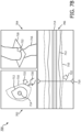
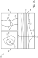
Figs. 7A-7C show anexemplary display 700 with various views showing imaging data according to aspects of the present disclosure. Thedisplay 700 may be displayed on themonitor 108.Fig. 7A shows adisplay 700 with threedifferent views view 702 is a longitudinal view of alumen 120,view 704 is a three dimensional cross section of thelumen 120, andview 706 is a transverse view of thelumen 120. Theviews 702 may include visualization ofboundaries boundary 710 may represent a vessel boundary,boundary 712 may represent a MLA of a portion of thelumen 120,boundary 714 may represent a central area of thelumen 120 andboundary 716 may represent a three dimensional vessel boundary. Furthermore, planes 718 and 719 may represent planes along which view 702 is viewed. Theboundaries boundaries other views display 700. The presentation of different views may help an operator to visualize the size and shape of portions of thelumen 120. -
Fig. 7B shows anexemplary display 700 with a function to allow the operator to edit one or more of the visualization of theboundaries Fig. 7B , the operator may use atool 720 to select a boundary to move (in this case, boundary 710). The selected boundary may appear as a dotted line. The boundary may be moved in any direction. In the example ofFig. 7B , anarrow 722 shows the direction that the boundary is moved (i.e., in an outward direction). A corresponding movement of the boundary is also shown inviews arrows 722 to show the direction of movement. The operator may move theboundaries -
Fig. 7C shows anexemplary display 700 after theboundary 710 has been moved to a new location atboundary 730. As discussed above, theviews show corresponding boundaries lumen 120. -
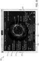
Fig. 8 shows anexemplary visualization 320 showing a lesion view according to aspects of the present disclosure. In some embodiments,visualization 320 corresponds to thepre-stent plan option 204 as shown inFig. 2 . In some embodiments, thevisualization 320 may be used to recommend the placement and size of a stent to address a lesion. These recommendations may be made automatically by thesystem 100 based on the imaging data received by thedevice 102. In particular, thevisualization 320 may be used to visualize a portion of alumen 120 with a potential "landing zone" 834 for a stent. In some embodiments, thelanding zone 834 is an area of interest within thelumen 120 that includes an MLA of a portion of thelumen 120, as marked bymarker 614. Thelanding zone 834 may be shown in profile inview 610 to show the potential placement of the stent within thelanding zone 834. Adistal end marker 830 and aproximal end marker 832 of thelanding zone 834 may define the distal and proximal extent of a potential stent. Thedistal end marker 830 andproximal end marker 832 may be accompanied withnumerical data lumen 120 at these locations. In some embodiments, the visualization may also a depiction of theplaque burden 852 along thelumen 120. In some embodiments, the depiction of theplaque burden 852 is automatically measured based on imaging data from thedevice 102. Thevisualization 320 may also include a depiction oflumen area 850. As illustrated inFig. 8 , themarker 614 for the MLA may be placed where the plaque burden is the greatest and the area of the lumen is the smallest. - In some embodiments, the
visualization 320 includes a recommended stent diameter as shown intext box 812. This diameter may be based on the diameter of thelumen 102 as measured by thesystem 100. -
Fig. 9 shows anexemplary visualization 330 showing a stent check view according to aspects of the present disclosure. In some embodiments, thevisualization 330 is shown after the operator has selected thestent check option 204 and has been guided through the subsequent workflow steps. Thevisualization 330 may display imaging data gathered from thedevice 102 during motion within a lumen 120 (such as a pullback procedure) where a stent has been placed, as well as imaging data of surrounding areas of the lumen. - Measurements and/or metrics corresponding to the imaging data may be performed automatically by the intravascular imaging system and displayed by the
visualization 330. For example, theintravascular imaging system 100 may be used to perform length measurements such as minimum, maximum, average, and mean lengths of features in the imaging data. The effective diameter of features may also be measured. Area measurements of features such as lumens, vessels, plaque, and thrombus may be performed by theintravascular imaging system 100. The measurements may include plaque burden, percent stenosis, percent difference, diameter stenosis, percent diameter stenosis, luminal gain, and luminal gain percentage. Furthermore, features of a stent may also be measured by theintravascular imaging system 100, including overall stent area, minimum stent area, average stent area, stent apposition, expansion, malapposition, and a stent score. Thevisualization 330 can include numerical values of one or more of these measurements or other graphical representations (e.g., shading, coloring, etc.), including graphical representations overlaid on or displayed separately/spaced from tomographic, longitudinal, and/or angiographic images of a vessel. - In some embodiments, the shape and size of a
lumen boundary 904 may be measured and displayed, as well a boundary of thestent 906. As inFigs. 6 and8 , the boundaries may be visualized in afirst view 604 as well as asecond view 610. Thevisualization 330 may also include measurements of the length of the stent. For example, thevisualization 330 may include adistal reference marker 930 and may include adepiction 934 of the stent. The average diameter and plaque burden at the distal reference marker may be shown intext box 916. The minimum stent area (MSA) may also be automatically measured and displayed in thetext box 912 as well as withMSA marker 914. - In some embodiments, the
visualization 330 may be used to determine the effectiveness of a stent. For example, thevisualization 330 may include measurements and depictions of any malapposition of the stent. Themalapposition areas first view 604 and thesecond view 610 so that an operator can better visualize the malapposition. Themalapposition areas malapposition areas device 102 during a pullback procedure of the stent. Thevisualization 330 may also include anexpansion score 910. In the example ofFig. 9 , the expansion score is 80%. This may signify that the stent is mostly expanded to contact thelumen 120, but a malapposition is present. In some embodiments, the expansion score may vary from 0% (where a stent is not yet extended within the stent ) to 100% (where a stent is completely expanded and no malappositions are present). Theexpansion score 910 may be determined automatically with the controller of thesystem 100 by comparing measurements of the border of thestent 906 to the borders of the lumen. In some embodiments, theexpansion score 910 is also based on the plaque burden and lumen area within the vessel. -
Fig. 10 is a flow diagram of amethod 1000 of proving a guided workflow for an intravascular imaging procedure to a user. In some embodiments, the steps of themethod 1000 may be carried out by theintravascular imaging system 100 and associated components as shown inFig. 1 . It is understood that the steps ofmethod 1000 may be performed in a different order than shown inFig. 10 , additional steps can be provided before, during, and after the steps, and/or some of the steps described can be replaced or eliminated in other embodiments. - At
step 1002, themethod 1000 may include providing a guided workflow to a user. The guided workflow may be provided as a series of prompts, instructions, and visualizations that are displayed on a display device, such asmonitor 108 as shown inFig. 1 . The guided workflow may help a user to easily and accurately perform each step of an intravascular imaging procedure. The guided workflow may present different options based on the selections of the user and may include checks of previous steps to ensure that all steps of the procedure have been performed. - At
step 1004, the method may include providing a selectable option for a pre-stent plan or a post-stent check. The selectable option may be provided on a display such asdisplay 200 as shown inFig. 2 . The selectable option for the pre-stent plan may include performing an intravascular imaging procedure to visualize a vessel or lumen before inserting a stent. The selectable option for the post-stent check may include performing an intravascular imaging procedure to check a stent that has been inserted in a vessel or lumen. Each selectable option may include a number of subsequent steps, as discussed below. - At
step 1006, themethod 1000 may include providing an option to select a target vessel. This option may be presented visually, such as presenting various vessels on a diagram. In some embodiments, the target vessels are arteries within the heart, such as the RCA, LAD, and LCX. In other embodiments, the target vessels are other lumens within the body. Thisstep 1006 may involve providing feedback to a user, such as indicating which vessel has been selected. The feedback may include highlighting, coloring, shading or otherwise indicating the vessel that has been selected. - At
step 1008, themethod 1000 may include providing a prompt to perform an operation within the selected target vessel. In some embodiments, this operation includes moving an intravascular device within the vessel. For example, the operation may be a pullback operation. In other embodiments, the operation may be an operation to push an intravascular device through a portion of a lumen. The prompt may be presented in text format and may include a visualization of the operation. - At
step 1010, themethod 1000 may include providing a prompt to navigate an intravascular device to a starting point in the selected target vessel and activate sensors in the intravascular device. This prompt may be presented with text as well as images showing where the user should place the intravascular device. In some embodiments, the prompt ofstep 1010 depends on the option selected atstep 1004. For example, if the user selected the pre-stent plan option atstep 1004, the prompt atstep 1010 may prompt the user to navigate the intravascular device from a most distal point of the target vessel to the ostium. If the user selected the post-stent check option atstep 1004, the prompt atstep 1010 may prompt the user to navigate the intravascular device from a distal end of the stent to a proximal end of the stent. - At
step 1012, themethod 1000 may include receiving imaging data from the intravascular device. This imaging data may help a user to accurately navigate the intravascular device according to the prompt ofstep 1010. For example, if the prompt ofstep 1010 directs the user to navigate the intravascular device from a distal end of the stent to a proximal end of the stent, the imaging data may show imaging data from the intravascular device as it is moved to the distal end of the stent. In some embodiments, the imaging data may include IVUS data showing the layers of tissue on the interior of the vessel. In other embodiments, the imaging data includes data from another modality such as OCT. Thus, the imaging data may help the user to accurately perform the operation outlined in the prompt. - At
step 1014, themethod 1000 may include displaying the imaging data as the intravascular device is moved during the operation. This imaging data may help a user to accurately perform the operation. - At
step 1016, themethod 1000 may include identifying an area of interest using the imaging data. In some embodiment, the area of interest is identified based on imaging data such as border measurements, lumen area, plaque burden within the lumen, etc. The area of interest may include an MLA or MSA as shown inFigs. 6 ,8 , and9 . In some embodiments, the area of interest includes a landing zone for stent placement or a stent that has been positioned in a lumen. The area of interest may be colored, highlighted, shaded, or otherwise indicated as an area of interest on a display of the imaging data. In some embodiments, the distal and proximal ends of the area of interest are shown as well as measurements of the size and position of the area of interest. - At step 1018, the
method 1000 may include displaying vessel measurements based on the imaging data corresponding with the area of interest. In some embodiments, vessel measurements such as vessel boundaries, stent boundaries, MLA, MSA, lumen area, plaque burden, and other measurements are displayed on the display. These measurements may be shown graphically (for example, by colored lines or regions) as well as textually (for example, in text boxes). The vessel measurements may also include recommendations (such as the recommended size and position of stents) and scores (such as stent expansion scores). The vessel measurements may allow a user to quickly identify problem areas within a lumen as well as possible solutions. - Persons skilled in the art will recognize that the apparatus, systems, and methods described above can be modified in various ways. Accordingly, persons of ordinary skill in the art will appreciate that the embodiments encompassed by the present disclosure are not limited to the particular exemplary embodiments described above. In that regard, although illustrative embodiments have been shown and described, a wide range of modification, change, and substitution is contemplated in the foregoing disclosure. It is understood that such variations may be made to the foregoing without departing from the scope of the present disclosure. Accordingly, it is appropriate that the appended claims be construed broadly and in a manner consistent with the present disclosure.
Claims (20)
- An intravascular imaging system, comprising:
a controller in communication with an intravascular imaging device, the controller configured to:provide, on a display device in communication with the controller, a selectable option to select a target vessel;provide a prompt to move the intravascular imaging device within the selected target vessel;receive imaging data from an imaging sensor during movement of the intravascular imaging device within the selected target vessel;identify an area of interest within the selected target vessel based on the received imaging data; andautomatically display, in response to identifying the area of interest, vessel measurements corresponding with the area of interest on the display device. - The intravascular imaging system of claim 1, further comprising:the intravascular imaging device, comprising:a flexible elongate member configured to be inserted into the target vessel of a patient;the imaging sensor disposed on a distal portion of the flexible elongate member; andthe display device.
- The intravascular imaging system of claim 1, wherein the controller is further configured to provide a selectable option on the display device to perform a pre-stent procedure or a post-stent check.
- The intravascular imaging system of claim 1, wherein the controller is further configured to automatically measure a diameter of the vessel within the area of interest, determine a first location within the area of interest with a minimum diameter, and display the first location and the minimum diameter on the display device.
- The intravascular imaging system of claim 1, wherein the display of the vessel measurements is configured to allow a user to edit a depiction of a border of the vessel.
- The intravascular imaging system of claim 5, wherein the display of the vessel measurements includes a first view and a second view of the area of interest different from the first view.
- The intravascular imaging system of claim 6, wherein a user's edit to the depiction of the border of the vessel is displayed in the first view and the second view of the area of interest.
- The intravascular imaging system of claim 3, wherein the display of the vessel measurements comprises a depiction of a target area for a stent if a user selects the pre-stent procedure option.
- The intravascular imaging system of claim 3, wherein the display of the vessel measurements comprises a depiction of a stent if a user selects the post-stent check option.
- The intravascular imaging system of claim 9, wherein the display of the vessel measurements further comprises a depiction of a stent malapposition.
- A method of intravascular imaging, comprising:providing, with a controller in communication with an intravascular imaging device, a selectable option on a display device to select a target vessel within a patient;providing, with the controller, a prompt to move the intravascular imaging device in the selected target vessel on the display device;receiving, with the controller, imaging data from an imaging sensor while the intravascular imaging device is moved within the selected target vessel;identifying, with the controller, an area of interest within the selected target vessel based on the received imaging data; anddisplaying automatically, with the display device, vessel measurements corresponding with the area of interest.
- The method of claim 11, further comprising providing, with a controller, a selectable option on a display device to perform a pre-stent procedure or a post-stent check.
- The method of claim 11, further comprising:measuring, with the controller, a diameter of the vessel within the area of interest,identifying a first location with a minimum diameter within the area of interest; anddisplaying the first location and minimum diameter on the display device.
- The method of claim 11, further comprising providing, with the controller, an option to edit a depiction of a border of the vessel on the display device.
- The method of claim 14, wherein the display of the vessel measurements includes a first view and a second view of the area of interest different from the first view.
- The method of claim 15, further comprising displaying an edit to the depiction of the border of the vessel in the first view and the second view of the area of interest.
- The method of claim 16, further comprising displaying the edit to the depiction of the border of the vessel in a third view different from the first view and the second view.
- The method of claim 12, wherein the display of the vessel measurements comprises a depiction of a target area for a stent if a user selects the pre-stent procedure option.
- The method of claim 12, wherein the display of the vessel measurements comprises a depiction of a stent if a user selects the post-stent check option.
- The method of claim 19, wherein the display of the vessel measurements further comprises a depiction of a stent malapposition.
Applications Claiming Priority (3)
| Application Number | Priority Date | Filing Date | Title |
|---|---|---|---|
| US201862712009P | 2018-07-30 | 2018-07-30 | |
| PCT/EP2019/069459 WO2020025352A1 (en) | 2018-07-30 | 2019-07-19 | Intravascular imaging procedure-specific workflow guidance and associated devices, systems, and methods |
| EP19745072.9A EP3829417B1 (en) | 2018-07-30 | 2019-07-19 | Intravascular imaging procedure-specific workflow guidance and associated devices, systems, and methods |
Related Parent Applications (1)
| Application Number | Title | Priority Date | Filing Date |
|---|---|---|---|
| EP19745072.9A Division EP3829417B1 (en) | 2018-07-30 | 2019-07-19 | Intravascular imaging procedure-specific workflow guidance and associated devices, systems, and methods |
Publications (2)
| Publication Number | Publication Date |
|---|---|
| EP4578381A2 true EP4578381A2 (en) | 2025-07-02 |
| EP4578381A3 EP4578381A3 (en) | 2025-08-20 |
Family
ID=67441092
Family Applications (2)
| Application Number | Title | Priority Date | Filing Date |
|---|---|---|---|
| EP25170272.6A Pending EP4578381A3 (en) | 2018-07-30 | 2019-07-19 | Intravascular imaging procedure-specific workflow guidance and associated devices, systems, and methods |
| EP19745072.9A Active EP3829417B1 (en) | 2018-07-30 | 2019-07-19 | Intravascular imaging procedure-specific workflow guidance and associated devices, systems, and methods |
Family Applications After (1)
| Application Number | Title | Priority Date | Filing Date |
|---|---|---|---|
| EP19745072.9A Active EP3829417B1 (en) | 2018-07-30 | 2019-07-19 | Intravascular imaging procedure-specific workflow guidance and associated devices, systems, and methods |
Country Status (5)
| Country | Link |
|---|---|
| US (3) | US11666245B2 (en) |
| EP (2) | EP4578381A3 (en) |
| JP (3) | JP7340594B2 (en) |
| CN (1) | CN112512409B (en) |
| WO (1) | WO2020025352A1 (en) |
Families Citing this family (18)
| Publication number | Priority date | Publication date | Assignee | Title |
|---|---|---|---|---|
| EP4230262A3 (en) | 2015-06-24 | 2023-11-22 | The Regents Of The University Of Michigan | Histotripsy therapy systems for the treatment of brain tissue |
| CN113286552B (en) | 2018-11-28 | 2025-05-02 | 希斯托索尼克斯公司 | Tissue destruction system and method |
| EP4589528A3 (en) | 2019-08-05 | 2025-10-22 | Lightlab Imaging, Inc. | Longitudinal display of coronary artery calcium burden |
| US12394080B2 (en) | 2019-12-10 | 2025-08-19 | Philips Image Guided Therapy Corporation | Intraluminal image-based vessel diameter determination and associated devices, systems, and methods |
| US20230045488A1 (en) * | 2020-01-06 | 2023-02-09 | Philips Image Guided Therapy Corporation | Intraluminal imaging based detection and visualization of intraluminal treatment anomalies |
| WO2021155026A1 (en) | 2020-01-28 | 2021-08-05 | The Regents Of The University Of Michigan | Systems and methods for histotripsy immunosensitization |
| JP7610929B2 (en) * | 2020-05-29 | 2025-01-09 | 富士フイルム株式会社 | Ultrasound imaging device and medical support system |
| JP2023530477A (en) | 2020-06-18 | 2023-07-18 | ヒストソニックス,インコーポレーテッド | Tissue-tripping acoustic/patient coupling system and method |
| EP4204084A4 (en) | 2020-08-27 | 2024-10-09 | The Regents Of The University Of Michigan | Ultrasound transducer with transmit-receive capability for histotripsy |
| WO2022238058A1 (en) | 2021-05-13 | 2022-11-17 | Koninklijke Philips N.V. | Preview of intraluminal ultrasound image along longitudinal view of body lumen |
| EP4351718A4 (en) | 2021-06-07 | 2025-03-26 | The Regents of The University of Michigan | Minimally invasive histotripsy systems and methods |
| IL308943A (en) | 2021-06-07 | 2024-01-01 | Univ Michigan Regents | All-in-one ultrasound systems and methods including histotripsy |
| US20230130046A1 (en) * | 2021-10-27 | 2023-04-27 | Canon U.S.A., Inc. | Devices, systems, and methods for displaying stenosis measurements and calculations |
| WO2023100979A1 (en) * | 2021-12-03 | 2023-06-08 | テルモ株式会社 | Information processing device, information processing method, and program |
| EP4561453A1 (en) * | 2022-09-14 | 2025-06-04 | Boston Scientific Scimed Inc. | Graphical user interface for intravascular ultrasound automated lesion assessment system |
| WO2024059140A1 (en) * | 2022-09-14 | 2024-03-21 | Boston Scientific Scimed, Inc. | Key frame identification for intravascular ultrasound based on plaque burden |
| AU2023366591A1 (en) | 2022-10-28 | 2025-04-24 | Histosonics, Inc. | Histotripsy systems and methods |
| WO2024221001A2 (en) | 2023-04-20 | 2024-10-24 | Histosonics, Inc. | Histotripsy systems and associated methods including user interfaces and workflows for treatment planning and therapy |
Citations (5)
| Publication number | Priority date | Publication date | Assignee | Title |
|---|---|---|---|---|
| US210117A (en) | 1878-11-19 | Improvement in car-couplings | ||
| US210217A (en) | 1878-11-26 | Improvement in accordions | ||
| US210317A (en) | 1878-11-26 | Improvement in induction apparatus for lighting by electricity | ||
| US236517A (en) | 1881-01-11 | Fornia | ||
| US7846101B2 (en) | 1995-12-26 | 2010-12-07 | Volcano Corporation | High resolution intravascular ultrasound transducer assembly having a flexible substrate |
Family Cites Families (27)
| Publication number | Priority date | Publication date | Assignee | Title |
|---|---|---|---|---|
| WO2006076409A2 (en) * | 2005-01-11 | 2006-07-20 | Volcano Corporation | Vascular image co-registration |
| US7860283B2 (en) * | 2006-10-25 | 2010-12-28 | Rcadia Medical Imaging Ltd. | Method and system for the presentation of blood vessel structures and identified pathologies |
| CN102202576B (en) * | 2008-10-10 | 2015-04-08 | 皇家飞利浦电子股份有限公司 | Angiographic image acquisition system and method with automatic shutter adaptation for yielding a reduced field of view covering a segmented target structure or lesion for decreasing x-radiation dose in minimally invasive x-ray-guided interventions |
| AU2010298333B2 (en) * | 2009-09-23 | 2014-04-17 | Lightlab Imaging, Inc. | Lumen morphology and vascular resistance measurements data collection systems, apparatus and methods |
| US12426789B2 (en) * | 2009-09-23 | 2025-09-30 | Lightlab Imaging, Inc. | Blood vessel lumen morphology and minimum lumen area measurements data collection by intravascular imaging systems for stenosis or stent planning |
| US20220139561A1 (en) * | 2009-09-25 | 2022-05-05 | Volcano Corporation | Device and Method for Determining the Likelihood of a Patient Having a Clinical Event or a Clinically Silent Event Based on Ascertained Physiological Parameters |
| US8548778B1 (en) * | 2012-05-14 | 2013-10-01 | Heartflow, Inc. | Method and system for providing information from a patient-specific model of blood flow |
| US10568586B2 (en) * | 2012-10-05 | 2020-02-25 | Volcano Corporation | Systems for indicating parameters in an imaging data set and methods of use |
| EP2934333B1 (en) * | 2012-12-21 | 2019-05-15 | Volcano Corporation | Method for multi-frequency imaging using high-bandwidth transducer outputs |
| EP2964089B1 (en) * | 2013-03-08 | 2021-11-03 | Lightlab Imaging, Inc. | Stent visualization and malapposition detection systems, devices, and methods |
| US10219887B2 (en) * | 2013-03-14 | 2019-03-05 | Volcano Corporation | Filters with echogenic characteristics |
| WO2015038786A2 (en) * | 2013-09-11 | 2015-03-19 | Boston Scientific Scimed, Inc. | Systems and methods for selection and displaying of images using an intravascular ultrasound imaging system |
| WO2015073357A1 (en) * | 2013-11-13 | 2015-05-21 | Volcano Corporation | Visually optimized intravascular imaging and associated devices, systems, and methods |
| US20150331995A1 (en) * | 2014-05-14 | 2015-11-19 | Tiecheng Zhao | Evolving contextual clinical data engine for medical data processing |
| WO2016007172A1 (en) * | 2014-07-11 | 2016-01-14 | Acist Medical Systems, Inc. | Intravascular imaging |
| US11166668B2 (en) * | 2014-07-24 | 2021-11-09 | Lightlab Imaging, Inc. | Pre and post stent planning along with vessel visualization and diagnostic systems, devices, and methods for automatically identifying stent expansion profile |
| CN106999076B (en) * | 2014-12-08 | 2021-10-22 | 皇家飞利浦有限公司 | Automatic identification and classification of intravascular lesions |
| JP6925268B2 (en) * | 2014-12-08 | 2021-08-25 | コーニンクレッカ フィリップス エヌ ヴェKoninklijke Philips N.V. | Devices and methods for recommending diagnostic procedures based on co-registration angiographic images and physiological information measured by intravascular devices |
| EP3838124A1 (en) * | 2014-12-12 | 2021-06-23 | Lightlab Imaging, Inc. | Systems to detect and display endovascular features |
| US9996921B2 (en) * | 2015-05-17 | 2018-06-12 | LIGHTLAB IMAGING, lNC. | Detection of metal stent struts |
| JP6866310B2 (en) * | 2016-01-26 | 2021-04-28 | テルモ株式会社 | Image display device and its control method |
| CN109716446B (en) * | 2016-09-28 | 2023-10-03 | 光学实验室成像公司 | Stent planning system and method utilizing blood vessel representation |
| CN107730540B (en) * | 2017-10-09 | 2020-11-17 | 全景恒升(北京)科学技术有限公司 | Coronary parameter calculation method based on high-precision matching model |
| WO2019175032A1 (en) * | 2018-03-14 | 2019-09-19 | Koninklijke Philips N.V. | Scoring intravascular lesions and stent deployment in medical intraluminal ultrasound imaging |
| WO2019174971A1 (en) | 2018-03-14 | 2019-09-19 | Koninklijke Philips N.V. | Alternative anatomical borders of blood vessels and associated devices, systems, and methods |
| WO2019175004A1 (en) * | 2018-03-15 | 2019-09-19 | Koninklijke Philips N.V. | Determination and visualization of anatomical landmarks for intraluminal lesion assessment and treatment planning |
| US20200029932A1 (en) | 2018-07-30 | 2020-01-30 | Koninklijke Philips N.V. | Systems, devices, and methods for displaying multiple intraluminal images in luminal assessment with medical imaging |
-
2019
- 2019-07-19 JP JP2021503870A patent/JP7340594B2/en active Active
- 2019-07-19 EP EP25170272.6A patent/EP4578381A3/en active Pending
- 2019-07-19 WO PCT/EP2019/069459 patent/WO2020025352A1/en not_active Ceased
- 2019-07-19 EP EP19745072.9A patent/EP3829417B1/en active Active
- 2019-07-19 CN CN201980050685.1A patent/CN112512409B/en active Active
- 2019-07-24 US US16/520,472 patent/US11666245B2/en active Active
-
2023
- 2023-06-06 US US18/206,175 patent/US12016675B2/en active Active
- 2023-08-28 JP JP2023137837A patent/JP2023162327A/en active Pending
-
2024
- 2024-06-24 US US18/752,259 patent/US20240341629A1/en active Granted
-
2025
- 2025-05-20 JP JP2025083812A patent/JP2025122081A/en active Pending
Patent Citations (5)
| Publication number | Priority date | Publication date | Assignee | Title |
|---|---|---|---|---|
| US210117A (en) | 1878-11-19 | Improvement in car-couplings | ||
| US210217A (en) | 1878-11-26 | Improvement in accordions | ||
| US210317A (en) | 1878-11-26 | Improvement in induction apparatus for lighting by electricity | ||
| US236517A (en) | 1881-01-11 | Fornia | ||
| US7846101B2 (en) | 1995-12-26 | 2010-12-07 | Volcano Corporation | High resolution intravascular ultrasound transducer assembly having a flexible substrate |
Also Published As
| Publication number | Publication date |
|---|---|
| US20200029861A1 (en) | 2020-01-30 |
| CN112512409A (en) | 2021-03-16 |
| US20230309859A1 (en) | 2023-10-05 |
| JP7340594B2 (en) | 2023-09-07 |
| US20240341629A1 (en) | 2024-10-17 |
| EP4578381A3 (en) | 2025-08-20 |
| JP2021531889A (en) | 2021-11-25 |
| EP3829417B1 (en) | 2025-04-23 |
| US12016675B2 (en) | 2024-06-25 |
| EP3829417A1 (en) | 2021-06-09 |
| JP2025122081A (en) | 2025-08-20 |
| JP2023162327A (en) | 2023-11-08 |
| CN112512409B (en) | 2024-10-18 |
| WO2020025352A1 (en) | 2020-02-06 |
| US11666245B2 (en) | 2023-06-06 |
Similar Documents
| Publication | Publication Date | Title |
|---|---|---|
| US12016675B2 (en) | Intravascular imaging procedure-specific workflow guidance and associated devices, systems, and methods | |
| US12226255B2 (en) | Systems, devices, and methods for displaying multiple intraluminal images in luminal assessment with medical imaging | |
| JP7679429B2 (en) | Scoring intravascular lesions and stent deployment in medical intraluminal ultrasound imaging | |
| US20230404491A1 (en) | Determination and visualization of anatomical landmarks for intraluminal lesion assessment and treatment planning | |
| EP4272654B1 (en) | Speed determination for intraluminal ultrasound imaging and associated devices, systems, and methods | |
| EP3870069B1 (en) | Intraluminal ultrasound directional guidance and associated devices and systems | |
| US20260123851A1 (en) | Intravascular imaging procedure-specific workflow guidance and associated devices, systems, and methods |
Legal Events
| Date | Code | Title | Description |
|---|---|---|---|
| PUAI | Public reference made under article 153(3) epc to a published international application that has entered the european phase |
Free format text: ORIGINAL CODE: 0009012 |
|
| STAA | Information on the status of an ep patent application or granted ep patent |
Free format text: STATUS: THE APPLICATION HAS BEEN PUBLISHED |
|
| AC | Divisional application: reference to earlier application |
Ref document number: 3829417 Country of ref document: EP Kind code of ref document: P |
|
| AK | Designated contracting states |
Kind code of ref document: A2 Designated state(s): AL AT BE BG CH CY CZ DE DK EE ES FI FR GB GR HR HU IE IS IT LI LT LU LV MC MK MT NL NO PL PT RO RS SE SI SK SM TR |
|
| REG | Reference to a national code |
Ref country code: DE Ref legal event code: R079 Free format text: PREVIOUS MAIN CLASS: A61B0005107000 Ipc: A61B0005000000 |
|
| PUAL | Search report despatched |
Free format text: ORIGINAL CODE: 0009013 |
|
| AK | Designated contracting states |
Kind code of ref document: A3 Designated state(s): AL AT BE BG CH CY CZ DE DK EE ES FI FR GB GR HR HU IE IS IT LI LT LU LV MC MK MT NL NO PL PT RO RS SE SI SK SM TR |
|
| RIC1 | Information provided on ipc code assigned before grant |
Ipc: A61B 5/00 20060101AFI20250715BHEP Ipc: A61B 8/12 20060101ALI20250715BHEP Ipc: A61B 5/02 20060101ALI20250715BHEP Ipc: A61B 5/107 20060101ALI20250715BHEP Ipc: A61B 8/08 20060101ALI20250715BHEP Ipc: A61B 8/00 20060101ALI20250715BHEP |
|
| STAA | Information on the status of an ep patent application or granted ep patent |
Free format text: STATUS: REQUEST FOR EXAMINATION WAS MADE |
|
| 17P | Request for examination filed |
Effective date: 20260220 |