EP4578339A2 - Assembled shelf - Google Patents
Assembled shelf Download PDFInfo
- Publication number
- EP4578339A2 EP4578339A2 EP25172845.7A EP25172845A EP4578339A2 EP 4578339 A2 EP4578339 A2 EP 4578339A2 EP 25172845 A EP25172845 A EP 25172845A EP 4578339 A2 EP4578339 A2 EP 4578339A2
- Authority
- EP
- European Patent Office
- Prior art keywords
- hanger
- clamping
- slot
- edge
- plug
- Prior art date
- Legal status (The legal status is an assumption and is not a legal conclusion. Google has not performed a legal analysis and makes no representation as to the accuracy of the status listed.)
- Pending
Links
Images





Classifications
-
- A—HUMAN NECESSITIES
- A47—FURNITURE; DOMESTIC ARTICLES OR APPLIANCES; COFFEE MILLS; SPICE MILLS; SUCTION CLEANERS IN GENERAL
- A47B—TABLES; DESKS; OFFICE FURNITURE; CABINETS; DRAWERS; GENERAL DETAILS OF FURNITURE
- A47B57/00—Cabinets, racks or shelf units, characterised by features for adjusting shelves or partitions
- A47B57/30—Cabinets, racks or shelf units, characterised by features for adjusting shelves or partitions with means for adjusting the height of detachable shelf supports
- A47B57/54—Cabinets, racks or shelf units, characterised by features for adjusting shelves or partitions with means for adjusting the height of detachable shelf supports consisting of clamping means, e.g. with sliding bolts or sliding wedges
-
- A—HUMAN NECESSITIES
- A47—FURNITURE; DOMESTIC ARTICLES OR APPLIANCES; COFFEE MILLS; SPICE MILLS; SUCTION CLEANERS IN GENERAL
- A47B—TABLES; DESKS; OFFICE FURNITURE; CABINETS; DRAWERS; GENERAL DETAILS OF FURNITURE
- A47B81/00—Cabinets or racks specially adapted for other particular purposes, e.g. for storing guns or skis
-
- A—HUMAN NECESSITIES
- A47—FURNITURE; DOMESTIC ARTICLES OR APPLIANCES; COFFEE MILLS; SPICE MILLS; SUCTION CLEANERS IN GENERAL
- A47B—TABLES; DESKS; OFFICE FURNITURE; CABINETS; DRAWERS; GENERAL DETAILS OF FURNITURE
- A47B96/00—Details of cabinets, racks or shelf units not covered by a single one of groups A47B43/00 - A47B95/00; General details of furniture
- A47B96/02—Shelves
- A47B96/024—Shelves characterised by support bracket location means, e.g. fixing means between support bracket and shelf
-
- A—HUMAN NECESSITIES
- A47—FURNITURE; DOMESTIC ARTICLES OR APPLIANCES; COFFEE MILLS; SPICE MILLS; SUCTION CLEANERS IN GENERAL
- A47B—TABLES; DESKS; OFFICE FURNITURE; CABINETS; DRAWERS; GENERAL DETAILS OF FURNITURE
- A47B47/00—Cabinets, racks or shelf units, characterised by features related to dismountability or building-up from elements
-
- A—HUMAN NECESSITIES
- A47—FURNITURE; DOMESTIC ARTICLES OR APPLIANCES; COFFEE MILLS; SPICE MILLS; SUCTION CLEANERS IN GENERAL
- A47B—TABLES; DESKS; OFFICE FURNITURE; CABINETS; DRAWERS; GENERAL DETAILS OF FURNITURE
- A47B47/00—Cabinets, racks or shelf units, characterised by features related to dismountability or building-up from elements
- A47B47/0058—Horizontal connecting members without panels
-
- A—HUMAN NECESSITIES
- A47—FURNITURE; DOMESTIC ARTICLES OR APPLIANCES; COFFEE MILLS; SPICE MILLS; SUCTION CLEANERS IN GENERAL
- A47B—TABLES; DESKS; OFFICE FURNITURE; CABINETS; DRAWERS; GENERAL DETAILS OF FURNITURE
- A47B47/00—Cabinets, racks or shelf units, characterised by features related to dismountability or building-up from elements
- A47B47/0083—Cabinets, racks or shelf units, characterised by features related to dismountability or building-up from elements with four vertical uprights
-
- A—HUMAN NECESSITIES
- A47—FURNITURE; DOMESTIC ARTICLES OR APPLIANCES; COFFEE MILLS; SPICE MILLS; SUCTION CLEANERS IN GENERAL
- A47B—TABLES; DESKS; OFFICE FURNITURE; CABINETS; DRAWERS; GENERAL DETAILS OF FURNITURE
- A47B47/00—Cabinets, racks or shelf units, characterised by features related to dismountability or building-up from elements
- A47B47/02—Cabinets, racks or shelf units, characterised by features related to dismountability or building-up from elements made of metal only
- A47B47/03—Cabinets, racks or shelf units, characterised by features related to dismountability or building-up from elements made of metal only with panels separate from the frame
-
- A—HUMAN NECESSITIES
- A47—FURNITURE; DOMESTIC ARTICLES OR APPLIANCES; COFFEE MILLS; SPICE MILLS; SUCTION CLEANERS IN GENERAL
- A47B—TABLES; DESKS; OFFICE FURNITURE; CABINETS; DRAWERS; GENERAL DETAILS OF FURNITURE
- A47B47/00—Cabinets, racks or shelf units, characterised by features related to dismountability or building-up from elements
- A47B47/04—Cabinets, racks or shelf units, characterised by features related to dismountability or building-up from elements made mainly of wood or plastics
- A47B47/05—Cabinets, racks or shelf units, characterised by features related to dismountability or building-up from elements made mainly of wood or plastics with panels on a separate frame, e.g. a metal frame
-
- A—HUMAN NECESSITIES
- A47—FURNITURE; DOMESTIC ARTICLES OR APPLIANCES; COFFEE MILLS; SPICE MILLS; SUCTION CLEANERS IN GENERAL
- A47B—TABLES; DESKS; OFFICE FURNITURE; CABINETS; DRAWERS; GENERAL DETAILS OF FURNITURE
- A47B57/00—Cabinets, racks or shelf units, characterised by features for adjusting shelves or partitions
- A47B57/30—Cabinets, racks or shelf units, characterised by features for adjusting shelves or partitions with means for adjusting the height of detachable shelf supports
- A47B57/32—Cabinets, racks or shelf units, characterised by features for adjusting shelves or partitions with means for adjusting the height of detachable shelf supports consisting of grooved or notched ledges, uprights or side walls
- A47B57/34—Cabinets, racks or shelf units, characterised by features for adjusting shelves or partitions with means for adjusting the height of detachable shelf supports consisting of grooved or notched ledges, uprights or side walls the grooved or notched parts being the side walls or uprights themselves
-
- A—HUMAN NECESSITIES
- A47—FURNITURE; DOMESTIC ARTICLES OR APPLIANCES; COFFEE MILLS; SPICE MILLS; SUCTION CLEANERS IN GENERAL
- A47B—TABLES; DESKS; OFFICE FURNITURE; CABINETS; DRAWERS; GENERAL DETAILS OF FURNITURE
- A47B96/00—Details of cabinets, racks or shelf units not covered by a single one of groups A47B43/00 - A47B95/00; General details of furniture
- A47B96/02—Shelves
- A47B96/021—Structural features of shelf bases
-
- A—HUMAN NECESSITIES
- A47—FURNITURE; DOMESTIC ARTICLES OR APPLIANCES; COFFEE MILLS; SPICE MILLS; SUCTION CLEANERS IN GENERAL
- A47B—TABLES; DESKS; OFFICE FURNITURE; CABINETS; DRAWERS; GENERAL DETAILS OF FURNITURE
- A47B96/00—Details of cabinets, racks or shelf units not covered by a single one of groups A47B43/00 - A47B95/00; General details of furniture
- A47B96/06—Brackets or similar supporting means for cabinets, racks or shelves
-
- A—HUMAN NECESSITIES
- A47—FURNITURE; DOMESTIC ARTICLES OR APPLIANCES; COFFEE MILLS; SPICE MILLS; SUCTION CLEANERS IN GENERAL
- A47B—TABLES; DESKS; OFFICE FURNITURE; CABINETS; DRAWERS; GENERAL DETAILS OF FURNITURE
- A47B96/00—Details of cabinets, racks or shelf units not covered by a single one of groups A47B43/00 - A47B95/00; General details of furniture
- A47B96/14—Bars, uprights, struts, or like supports, for cabinets, brackets, or the like
-
- A—HUMAN NECESSITIES
- A47—FURNITURE; DOMESTIC ARTICLES OR APPLIANCES; COFFEE MILLS; SPICE MILLS; SUCTION CLEANERS IN GENERAL
- A47B—TABLES; DESKS; OFFICE FURNITURE; CABINETS; DRAWERS; GENERAL DETAILS OF FURNITURE
- A47B96/00—Details of cabinets, racks or shelf units not covered by a single one of groups A47B43/00 - A47B95/00; General details of furniture
- A47B96/14—Bars, uprights, struts, or like supports, for cabinets, brackets, or the like
- A47B96/1441—Horizontal struts
-
- A—HUMAN NECESSITIES
- A47—FURNITURE; DOMESTIC ARTICLES OR APPLIANCES; COFFEE MILLS; SPICE MILLS; SUCTION CLEANERS IN GENERAL
- A47B—TABLES; DESKS; OFFICE FURNITURE; CABINETS; DRAWERS; GENERAL DETAILS OF FURNITURE
- A47B96/00—Details of cabinets, racks or shelf units not covered by a single one of groups A47B43/00 - A47B95/00; General details of furniture
- A47B96/14—Bars, uprights, struts, or like supports, for cabinets, brackets, or the like
- A47B96/1466—Bars, uprights, struts, or like supports, for cabinets, brackets, or the like with longitudinal grooves
-
- F—MECHANICAL ENGINEERING; LIGHTING; HEATING; WEAPONS; BLASTING
- F16—ENGINEERING ELEMENTS AND UNITS; GENERAL MEASURES FOR PRODUCING AND MAINTAINING EFFECTIVE FUNCTIONING OF MACHINES OR INSTALLATIONS; THERMAL INSULATION IN GENERAL
- F16B—DEVICES FOR FASTENING OR SECURING CONSTRUCTIONAL ELEMENTS OR MACHINE PARTS TOGETHER, e.g. NAILS, BOLTS, CIRCLIPS, CLAMPS, CLIPS OR WEDGES; JOINTS OR JOINTING
- F16B12/00—Jointing of furniture or the like, e.g. hidden from exterior
- F16B12/40—Joints for furniture tubing
- F16B12/42—Joints for furniture tubing connecting furniture tubing to non-tubular parts
-
- F—MECHANICAL ENGINEERING; LIGHTING; HEATING; WEAPONS; BLASTING
- F16—ENGINEERING ELEMENTS AND UNITS; GENERAL MEASURES FOR PRODUCING AND MAINTAINING EFFECTIVE FUNCTIONING OF MACHINES OR INSTALLATIONS; THERMAL INSULATION IN GENERAL
- F16B—DEVICES FOR FASTENING OR SECURING CONSTRUCTIONAL ELEMENTS OR MACHINE PARTS TOGETHER, e.g. NAILS, BOLTS, CIRCLIPS, CLAMPS, CLIPS OR WEDGES; JOINTS OR JOINTING
- F16B12/00—Jointing of furniture or the like, e.g. hidden from exterior
- F16B12/44—Leg joints; Corner joints
- F16B12/50—Metal corner connections
-
- F—MECHANICAL ENGINEERING; LIGHTING; HEATING; WEAPONS; BLASTING
- F16—ENGINEERING ELEMENTS AND UNITS; GENERAL MEASURES FOR PRODUCING AND MAINTAINING EFFECTIVE FUNCTIONING OF MACHINES OR INSTALLATIONS; THERMAL INSULATION IN GENERAL
- F16B—DEVICES FOR FASTENING OR SECURING CONSTRUCTIONAL ELEMENTS OR MACHINE PARTS TOGETHER, e.g. NAILS, BOLTS, CIRCLIPS, CLAMPS, CLIPS OR WEDGES; JOINTS OR JOINTING
- F16B7/00—Connections of rods or tubes, e.g. of non-circular section, mutually, including resilient connections
- F16B7/04—Clamping or clipping connections
- F16B7/044—Clamping or clipping connections for rods or tubes being in angled relationship
- F16B7/048—Clamping or clipping connections for rods or tubes being in angled relationship for rods or for tubes without using the innerside thereof
-
- F—MECHANICAL ENGINEERING; LIGHTING; HEATING; WEAPONS; BLASTING
- F16—ENGINEERING ELEMENTS AND UNITS; GENERAL MEASURES FOR PRODUCING AND MAINTAINING EFFECTIVE FUNCTIONING OF MACHINES OR INSTALLATIONS; THERMAL INSULATION IN GENERAL
- F16B—DEVICES FOR FASTENING OR SECURING CONSTRUCTIONAL ELEMENTS OR MACHINE PARTS TOGETHER, e.g. NAILS, BOLTS, CIRCLIPS, CLAMPS, CLIPS OR WEDGES; JOINTS OR JOINTING
- F16B12/00—Jointing of furniture or the like, e.g. hidden from exterior
- F16B12/44—Leg joints; Corner joints
- F16B12/46—Non-metal corner connections
Definitions
- Shelves are often used to place goods in our daily life.
- most of the existing shelves can be detached and assembled; most of the assembled shelves on the market are mainly composed of uprights, beams, plates, connecting fixtures and snap-on locators.
- the two ends of the beams are fixedly connected to the uprights through snap-on locators and connecting fixtures.
- the snap-on locators of the existing structure are mostly composed of two pieces A and B that are matched with each other, and then a fixing member is used to fix the two together and to buckle into a slot in the upright;
- a large number of the snap-on locators A and snap-on locators B are required, and each time a buckle is assembled, the corresponding snap-on locators A and snap-on locators B must be found, so the installation is more troublesome and the assembly efficiency is reduced; in addition, the fixing effect between the snap-on locators and the connecting fixtures is not satisfying, resulting in weak load-bearing capacity and stability of the shelves.
- the purpose of the present disclosure is to provide a conveniently assembled shelf, with the advantages of convenient and quick assembly and better stability, aiming at solving the technical problems of the existing shelf structure being inconvenient to assemble and having weak stability.
- the technical solution of the present disclosure is:
- the first side edge is provided with a plurality of positioning grooves at intervals along its vertical direction, and the hanging hook portion is provided with clamping blocks for matching and inserting into the positioning groove.
- an opening of the positioning groove faces a side away from the hanger body.
- a cross section of the hanging hook portion is L-shaped and can be buckled on the first side edge.
- a side of the hanger body facing the fastener body is provided with a plurality of vertically arranged engaged grooves, and a surface of the fastener body facing the hanger body is provided with engaging blocks for matching engaged grooves, and a top of the engaged groove is opening, allowing the engaging block to be inserted.
- a cross section of the engaged groove is L-shaped with a narrow notch and a wide inside
- a cross section of the engaging block is an inverted L-shaped with a narrow root and a wide outside for matching the engaged groove
- a cross section of the fastening hook portion is inverted L-shaped and can be buckled on the second side edge.
- a side of the hanger body away from the hanging hook portion is provided with a positioning extension edge extending to the second side edge, the positioning extension edge can be laid on the second side edge, and a cross section of the fastened hook portion is inverted L-shaped and can be buckled on the positioning extension edge and the second side edge.
- the first side surface is provided with a plug-in slot
- the clamping body is provided with a plug-in strip for matching and inserting into the plug-in slot.
- the plug-in slot includes an upper plug-in slot provided on the first side surface, an upper side wall of the upper plug-in slot is provided with a slot portion that is recessed upward, the plug-in strip includes an upper plug-in strip that can be matched and inserted in the upper plug-in slot, and the upper plug-in strip is provided with a clamp edge portion that protrudes upward to extend into the slot portion.
- a top plate is provided at an upper end of the main beam, the upper plug-in slot is located at a connection between the first side surface and the top plate and extends along a transverse direction, an upper convex edge is provided at an edge of the top plate and is bent downward into the upper plug-in slot, and the slot portion is formed between the upper convex edge and the first side surface.
- a bottom plate is provided at a lower end of the main beam
- the plug-in slot includes a lower plug-in slot that is laterally provided at a connection between the first side surface and the bottom plate and is recessed inward
- the plug-in strip includes a lower plug-in strip that can be matched and inserted into the lower plug-in slot.
- the positioning hanger 3 includes a hanger body 31 located between the first side edge 21 and the second side edge 22, the hanger body 31 is provided with a hanging hook portion 32 extending toward the first side edge 21, and the hanging hook portion 32 can be positioned and clamped on the first side edge 21.
- the positioning hanger 3 is configured as a whole.
- the hanger body 31 is attached to a surface of the upright 2 located between the first side edge 21 and the second side edge 22, and the hook portion 32 extends to the first side edge 21 to form a positioning clamp, so that the positioning hanger 3 can be detachably hung and mounted on the upright 2.
- the present disclosure has the advantage of convenient assembly.
- an opening of the positioning groove 23 faces to a side away from of the hanger body 31, and the first side edge 21 are provided on the edge of the same side surface of the upright 2 of the present disclosure, and the positioning grooves 23 are provided opposite to each other on a side of the two first side edge 21 close to each other.
- one of the hanger body 31 and the fastener body 41 is provided with an engaged groove 34, and the other is provided with an engaging block 44 for inserting and matching with the engaged groove 34.
- the hanger body 31 and the fastener body 41 are connected through the engaged groove 34 and the engaging block 44, thereby improving the connection stability.
- the engaged grooves 34 are multiple and arranged side by side on a side of the hanger body 31 facing the fastener body 41.
- two engaged grooves 34 are arranged to further improve the assembly stability.
- a cross-section of the engaged groove 34 is L-shaped with a narrow groove opening and a wide inside.
- the engaging block 44 is arranged on a surface of the fastener body 41 facing the hanger body 31, and a cross-section of the engaging block 44 is an inverted L-shape with a narrow root and s wide outside for matching with the engaged groove 34.
- the engaged groove 34 is configured as an L-shape with a narrow groove opening and a wide inside, which can make the connection between the two more stable and improve the assembly stability.
- a cross section of the fastening hook portion 42 is an inverted L-shape and can be fastened on the second side 22.
- the positioning hanger 3 is first pre-positioned on the upright 2, and then the fastening hook portion 42 of the locking fastener 4 is fastened to the second side edge 22, and the locking fastener 4 is slides downward from the upper side of the positioning hanger 3.
- the engaged block 44 on the hanger body 31 enters the engaged groove 34 on the fastener body 41 to form an engagement, and the positioning hanger 3 between the locking fastener 4 and the upright 2 is locked to improve the assembly stability.
- the other end of the secondary beam 5 is detachably assembled on the upright 2 through the above-mentioned structure.
- the positioning hanger 3 is first positioned and clamped on the first side edge 21, so the positioning hanger 3 is pre-positioned on the upright 2, and then the locking fastener 4 is buckled on the second side edge 22.
- the locking fastener 4 is embedded into the positioning hanger 3, to form a stable connection between the two, and the positioning hanger 3 positioned and clamped on the upright 2 is tightly locked.
- the secondary beam 5 is connected to the locking fastener 4, thus the secondary beam 5 is detachably and firmly connected to the upright 2.
- the present disclosure is assembled more conveniently and quickly, the stability of the conveniently assembled shelf is better and the practicability is high.
Landscapes
- Engineering & Computer Science (AREA)
- General Engineering & Computer Science (AREA)
- Mechanical Engineering (AREA)
- Life Sciences & Earth Sciences (AREA)
- Wood Science & Technology (AREA)
- Assembled Shelves (AREA)
Abstract
Description
- The present disclosure relates to the technical field of shelves, and in particular to a shelf convenient for assembly.
- Shelves are often used to place goods in our daily life. In order to meet the needs of use and facilitate transportation and handling, most of the existing shelves can be detached and assembled; most of the assembled shelves on the market are mainly composed of uprights, beams, plates, connecting fixtures and snap-on locators. The two ends of the beams are fixedly connected to the uprights through snap-on locators and connecting fixtures. The snap-on locators of the existing structure are mostly composed of two pieces A and B that are matched with each other, and then a fixing member is used to fix the two together and to buckle into a slot in the upright;
In the process of assembling the shelves, a large number of the snap-on locators A and snap-on locators B are required, and each time a buckle is assembled, the corresponding snap-on locators A and snap-on locators B must be found, so the installation is more troublesome and the assembly efficiency is reduced; in addition, the fixing effect between the snap-on locators and the connecting fixtures is not satisfying, resulting in weak load-bearing capacity and stability of the shelves. - The purpose of the present disclosure is to provide a conveniently assembled shelf, with the advantages of convenient and quick assembly and better stability, aiming at solving the technical problems of the existing shelf structure being inconvenient to assemble and having weak stability.
- In order to solve the above technical problems, the technical solution of the present disclosure is:
- A conveniently assembled shelf, includes main beams and uprights, wherein the upright has a first side edge and a second side edge opposite to each other. The main beam is detachably fixed to the upright through a shelf beam connection structure, wherein the shelf beam connection structure includes a positioning hanger and a locking fastener cooperated with each other;
- The positioning hanger includes a hanger body located between the first side edge and the second side edge, the hanger body is provided with a hanging hook portion extending toward the first side edge, and the hanging hook portion can be positioned and buckled on the first side edge;
- The locking fastener includes a fastener body connected to the main beam on one side, and the fastener body is detachably embedded into the hanger body on the other side, wherein the fastener body is provided with a fastening hook portion extending toward the second side edge, and the fastening hook portion can be fastened and clamped on the second side edge.
- The conveniently assembled shelf as described above, the first side edge is provided with a plurality of positioning grooves at intervals along its vertical direction, and the hanging hook portion is provided with clamping blocks for matching and inserting into the positioning groove.
- The conveniently assembled shelf as described above, an opening of the positioning groove faces a side away from the hanger body.
- The conveniently assembled shelf as described above, a cross section of the hanging hook portion is L-shaped and can be buckled on the first side edge.
- The conveniently assembled shelf as described above, a side of the hanger body facing the fastener body is provided with a plurality of vertically arranged engaged grooves, and a surface of the fastener body facing the hanger body is provided with engaging blocks for matching engaged grooves, and a top of the engaged groove is opening, allowing the engaging block to be inserted.
- The conveniently assembled shelf as described above, a cross section of the engaged groove is L-shaped with a narrow notch and a wide inside, and a cross section of the engaging block is an inverted L-shaped with a narrow root and a wide outside for matching the engaged groove.
- The conveniently assembled shelf as described above, a cross section of the fastening hook portion is inverted L-shaped and can be buckled on the second side edge.
- The conveniently assembled shelf as described above, a side of the hanger body away from the hanging hook portion is provided with a positioning extension edge extending to the second side edge, the positioning extension edge can be laid on the second side edge, and a cross section of the fastened hook portion is inverted L-shaped and can be buckled on the positioning extension edge and the second side edge.
- The conveniently assembled shelf as described above, the conveniently assembled shelf further includes secondary beams, one end of the secondary beam is detachably fixed to the main beam through a secondary shelf beam body connection structure, the main beam has a first side surface and a second side surface opposite to each other, the secondary shelf beam body connection structure includes a clamping fastener and a connecting hanger that cooperate with each other;
- The snap-on fastener is detachably provided on the main beam, including a clamping body clamped on the first side surface, the clamping body is provided with a clamping hook member extending to the second side surface, the clamping hook member can be clamped on the second side surface;
- One side of the connecting hanger is connected to the secondary beam, and the other side is detachably embedded with the clamping body.
- The conveniently assembled shelf as described above, the first side surface is provided with a plug-in slot, and the clamping body is provided with a plug-in strip for matching and inserting into the plug-in slot.
- The conveniently assembled shelf as described above, the plug-in slot includes an upper plug-in slot provided on the first side surface, an upper side wall of the upper plug-in slot is provided with a slot portion that is recessed upward, the plug-in strip includes an upper plug-in strip that can be matched and inserted in the upper plug-in slot, and the upper plug-in strip is provided with a clamp edge portion that protrudes upward to extend into the slot portion.
- The conveniently assembled shelf as described above, a top plate is provided at an upper end of the main beam, the upper plug-in slot is located at a connection between the first side surface and the top plate and extends along a transverse direction, an upper convex edge is provided at an edge of the top plate and is bent downward into the upper plug-in slot, and the slot portion is formed between the upper convex edge and the first side surface.
- The conveniently assembled shelf as described above, a bottom plate is provided at a lower end of the main beam, the plug-in slot includes a lower plug-in slot that is laterally provided at a connection between the first side surface and the bottom plate and is recessed inward, and the plug-in strip includes a lower plug-in strip that can be matched and inserted into the lower plug-in slot.
- The conveniently assembled shelf as described above, the clamping hook member includes an extension plate extending from a lower side of the clamping body to a bottom of the main beam, and the extension plate is provided with a clamping hook foot that is tilted upward at the end away from the snap-on body, and the clamping hook foot can be fastened on the lower edge of the second side edge.
- The conveniently assembled shelf as described above, a main embedding groove is arranged on a surface of the clamping body facing the connecting hanger, the main embedding groove is vertically arranged with an opening at the top, a cross section of the main embedding groove is an L-shaped with a narrow notch and a wide inside, and a main embedding block is arranged on a surface of the connecting hanger facing the clamping body, a cross section of the main embedding block is an inverted L-shaped with a narrow root and a wide outside for matching and inserting with the main embedding groove.
- The conveniently assembled shelf as described above, the side of the clamping body is arranged with a side embedding groove, the side embedding groove is vertically arranged with an opening at the top, and one side of the connecting hanger is arranged with a side embedding hook extending toward the side of the clamping body, and an end of the side embedding hook away from the connecting hanger can be matched and fastened into the main embedding groove.
- Compared with the prior art, the beneficial effects of the present disclosure are as follows:
- 1. The present disclosure provides a conveniently assembled shelf, including main beams and uprights, wherein the main beam is detachably fixed to the upright through a shelf beam connection structure, and the shelf beam connection structure includes a positioning hanger and a locking fastener that are cooperated with each other. When assembling, the hanger body of the positioning hanger is attached to a surface of the upright located between the first side edge and the second side edge, and the hanging hook portion is positioned and clamped on the second side edge, so the positioning hanger is pre-positioned on the upright. Then the fastening hook portion on the locking fastener is fastened and clamped on the second side edge, and a stable connection is formed between the positioning hanger and the locking fastener through the engagement between the hanger body and the fastener body, and the positioning hanger clamped on the upright is locked. Next, the main beam is connected to the locking fastener, and thus the main beam is detachably and firmly connected to the upright. Compared with the prior art, the present disclosure is assembled more conveniently and quickly, and the conveniently assembled shelf is more stable and practical.
- 2. The present disclosure also includes a secondary shelf, wherein the secondary beam is detachably fixed to the main beam through the secondary shelf beam body connection structure, and the secondary shelf beam body connection structure includes a clamping fastener and a connecting hanger that are cooperated with each other. When assembling, the clamping body is first clamped on a first side surface of the main beam, and then the clamping hook member on the clamping body is clamped on a second side surface the snap-on fastener is detachably connected to the main beam, and the connecting hanger is embedded into the snap-on fastener body to form a stable connection between the two, and then the secondary beam is connected to the other side of the connecting hanger, so the secondary beam is detachably and firmly connected to the main beam. Compared with the existing ones, the present disclosure is assembled more conveniently and quickly, and the conveniently assembled shelf is more stable and practical.
-
-
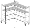
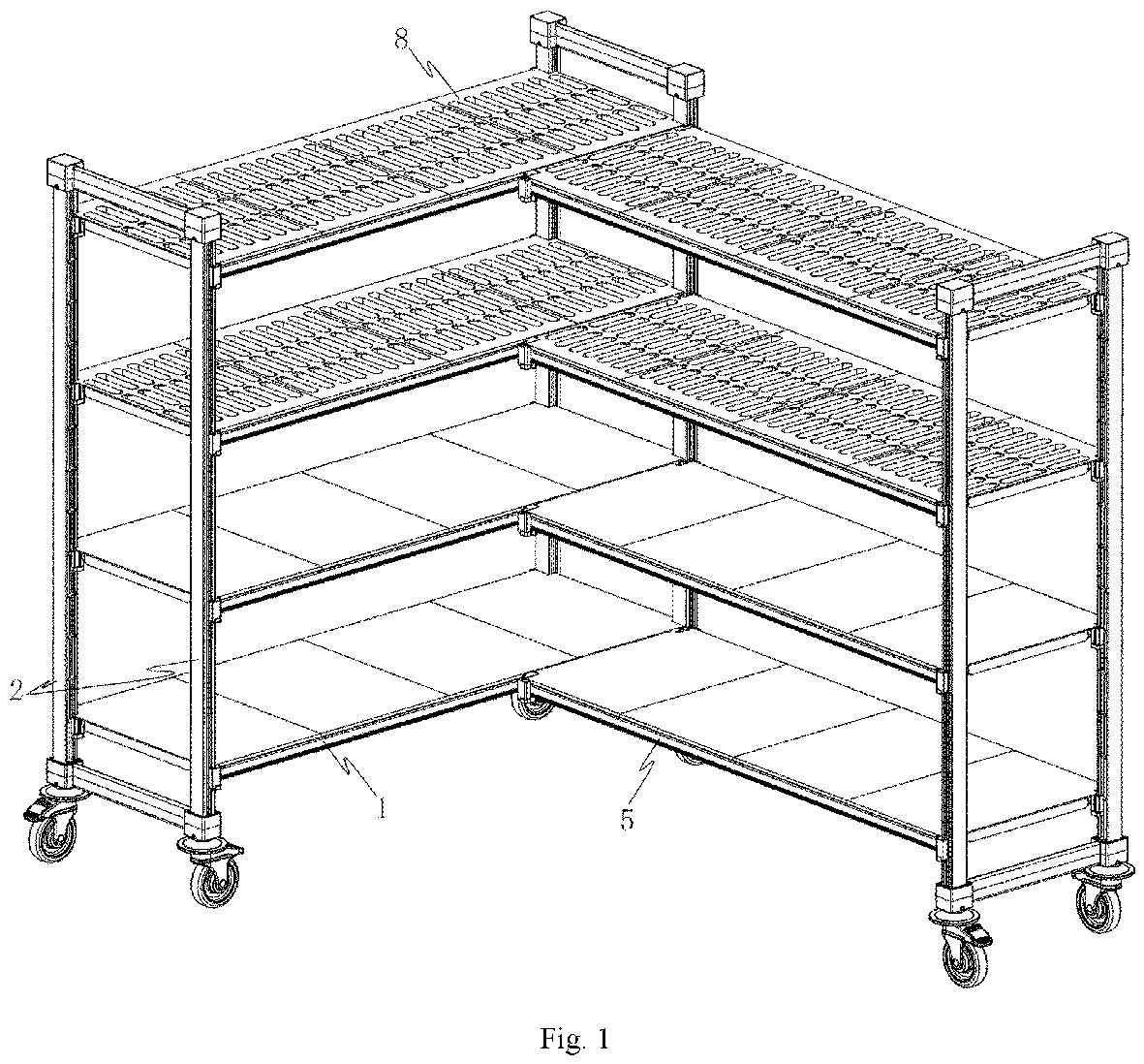
Fig. 1 is a schematic diagram of the structure of a shelf in an embodiment of the present disclosure; -
Fig. 2 is a schematic diagram of the structure of the shelf hiding layers in the embodiment of the present disclosure; -
Fig. 3 is a schematic diagram of the structure of the shelf hiding layers in another perspective in the embodiment of the present disclosure; -
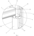
Fig. 4 is an enlarged schematic diagram of part A inFig. 2 ; -
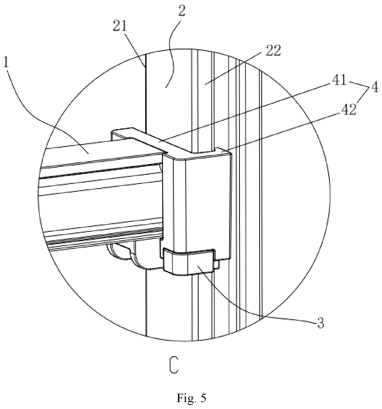
Fig. 5 is an enlarged schematic diagram of part C inFig. 3 ; -
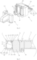
Fig. 6 is a schematic diagram of the decomposition of a shelf beam body connection structure in the embodiment of the present disclosure; -
Fig. 7 is a schematic diagram of the decomposition of the shelf beam body connection structure in another perspective in the embodiment of the present disclosure; -
Fig. 8 is a cross-sectional schematic diagram of the shelf beam body connection structure after being assembled in the embodiment of the present disclosure; -
Fig. 9 is an enlarged schematic diagram of part B inFig. 2 ; -
Fig. 10 is an enlarged schematic diagram of part D inFig. 3 ; -
Fig. 11 is a schematic diagram of the decomposition of a secondary shelf beam body connection structure according to the embodiment of the present disclosure; -
Fig. 12 is a schematic diagram of the decomposition of the secondary shelf beam body connection structure in another perspective in the embodiment of the present disclosure; -
Fig. 13 is a schematic diagram of the longitudinal section of the secondary shelf beam body connection structure after being assembled in the embodiment of the present disclosure; -
Fig. 14 is a cross-sectional schematic diagram of the assembled shelf beam body connection structure in the embodiment of the present disclosure. - In order to make the technical problems, technical solutions and beneficial effects solved by the present disclosure more clearly understood, the present disclosure is further described in detail below in conjunction with the accompanying drawings and embodiments. It should be known that the specific embodiments described herein are only used to explain instead of to limit the present disclosure.
- As shown in
Figs. 1-14 , a conveniently assembled shelf includes a main shelf, which includes at leastmain beams 1 anduprights 2. The upright 2 has afirst side edge 21 and asecond side edge 22 that are opposite to each other. Themain beam 1 is detachably fixed to the upright 2 through a shelf beam body connection structure. The shelf beam connection structure includes apositioning hanger 3 and alocking fastener 4 that are cooperated with each other; thepositioning hanger 3 includes ahanger body 31 located between thefirst side edge 21 and thesecond side edge 22, and thehanger body 31 is provided with ahanging hook portion 32 extending toward thefirst side edge 21, and thehanging hook portion 32 can be positioned and clamped on thefirst side edge 21; thelocking fastener 4 includes afastener body 41 connected to themain beam 1 on one side, and afastener body 41 detachably engaged with thehanger body 31 on the other side; thefastener body 41 is provided with afastening hook portion 42 extending toward thesecond side edge 22, and thefastening hook portion 42 can be fastened and clamped on thesecond side edge 22. When the present disclosure is assembled, thehanger body 31 of thepositioning hanger 3 is attached to a surface of theupright 2 located between thefirst side edge 21 and thesecond side edge 22, and the hanginghook portion 32 is positioned and clamped on thesecond side edge 22, so that thepositioning hanger 3 is pre-positioned on theupright 2, and then thefastening hook portion 42 on the lockingfastener 4 is fastened and clamped on thesecond side edge 22, and thepositioning hanger 3 and the lockingfastener 4 are firmly connected through the engagement between thehanger body 31 and thefastener body 41, and thepositioning hanger 3 positioned and clamped on theupright 2 is locked, and then themain beam 1 is connected to the lockingfastener 4, so that the main beam is detachably and firmly connected to the upright. Compared with the existing ones, the assembly of the present disclosure is more convenient and quicker, and the conveniently assembled shelf is more stable and practical. - Further, as shown in
Figs. 6-8 , thepositioning hanger 3 includes ahanger body 31 located between thefirst side edge 21 and thesecond side edge 22, thehanger body 31 is provided with a hanginghook portion 32 extending toward thefirst side edge 21, and the hanginghook portion 32 can be positioned and clamped on thefirst side edge 21. Compared with the existing assembly structure that two buckle positioning locating members for assembly, thepositioning hanger 3 is configured as a whole. When assembling, thehanger body 31 is attached to a surface of theupright 2 located between thefirst side edge 21 and thesecond side edge 22, and thehook portion 32 extends to thefirst side edge 21 to form a positioning clamp, so that thepositioning hanger 3 can be detachably hung and mounted on theupright 2. The present disclosure has the advantage of convenient assembly. - Further, as shown in
Figs. 6-8 , the lockingfastener 4 includes afastener body 41 connected to themain beam 1 on one side, and thefastener body 41 detachably engaged with thehanger body 31 on the other side. Thefastener body 41 is provided with afastening hook portion 42 extending toward thesecond side edge 22, and thefastening hook portion 42 can be fastened and clamped on thesecond side edge 22. Thefastener body 41 and thehanger body 31 of the present disclosure are designed to be engaged, which can improve the stability of the connection. Thefastening hook portion 42 can be fastened and clamped on thesecond side edge 22, so thehanger body 31 embedded in thefastener body 41 can be locked through this design, and thus the lockingfastener 4 and thepositioning hanger 3 are fixedly connected to theupright 2. In the present disclosure, a connectingcolumn 46 is configured to thefastener body 41 on the side away from thepositioning hanger 3 and is used to being plugged into themain beam 1. With this design, themain beam 1 can be detachably and firmly connected to theupright 2. - Furthermore, as shown in
Figs. 1-4 , thefirst side edge 21 is provided with a plurality ofpositioning grooves 23 at intervals along the vertical direction thereof. As shown inFigs. 7 and 8 , the hanging hookinghook 32 is provided with afastening block 33 that is matched and clamped into thepositioning groove 23. Thepositioning groove 23 is used to clamp theclamping block 33, so that thepositioning hanger 3 can maintain a certain height. The present disclosure provides a plurality ofpositioning grooves 23 arranged at intervals along a vertical direction on thefirst side edge 21, in this way, the shelf beam body connection structure with corresponding height can be assembled according to the required height, so as to place layers 8 with different heights accordingly. Of course, the height interval between each layer 8 can also be adjusted according to the required interlayer height, which has the advantage of better adaptability. - Furthermore, as shown in
Fig. 4 , an opening of thepositioning groove 23 faces to a side away from of thehanger body 31, and thefirst side edge 21 are provided on the edge of the same side surface of theupright 2 of the present disclosure, and thepositioning grooves 23 are provided opposite to each other on a side of the twofirst side edge 21 close to each other. With this design, when the clampingblock 33 on thepositioning hanger 3 is inserted into thepositioning groove 23, a lateral constraint is formed to facilitate pre-positioning. - Furthermore, as shown in
Figs. 7 and 8 , a cross section of the hanginghook portion 32 is L-shaped and can be fastened on thefirst side edge 21, in this way, a side of thepositioning hanger 3 and thefirst side edge 21 can be horizontally constrained, and the clampingblock 33 on the hanginghook portion 32 can be inserted into thepositioning groove 23 to form a vertical constraint, so that thepositioning hanger 3 can be pre-positioned on theupright 2, which is convenient for the subsequent locking of the lockingfastener 4. - Furthermore, as shown in
Figs. 6-8 , one of thehanger body 31 and thefastener body 41 is provided with an engagedgroove 34, and the other is provided with an engagingblock 44 for inserting and matching with the engagedgroove 34. In the present disclosure, thehanger body 31 and thefastener body 41 are connected through the engagedgroove 34 and the engagingblock 44, thereby improving the connection stability. - Furthermore, as shown in
Figs 6-8 , the engagedgroove 34 is vertically arranged and a top portion thereof is provided with an opening for inserting the engagingblock 44. When assembling, thepositioning hanger 3 is first pre-positioned on theupright 2, and then the lockingfastener 4 is slid downward from an upper side of thepositioning hanger 3. At this time, the engagingblock 44 on thehanger body 31 enters into the engaginggroove 34 on thefastener body 41 to form an engagement, thereby improving the assembly stability. - Furthermore, as shown in
Figs. 6-8 , the engagedgrooves 34 are multiple and arranged side by side on a side of thehanger body 31 facing thefastener body 41. In the specific embodiment of the present disclosure, two engagedgrooves 34 are arranged to further improve the assembly stability. A cross-section of the engagedgroove 34 is L-shaped with a narrow groove opening and a wide inside. The engagingblock 44 is arranged on a surface of thefastener body 41 facing thehanger body 31, and a cross-section of the engagingblock 44 is an inverted L-shape with a narrow root and s wide outside for matching with the engagedgroove 34. The engagedgroove 34 is configured as an L-shape with a narrow groove opening and a wide inside, which can make the connection between the two more stable and improve the assembly stability. - Furthermore, as shown in
Figs. 5-8 , a cross section of thefastening hook portion 42 is an inverted L-shape and can be fastened on thesecond side 22. When the present disclosure is assembled, thepositioning hanger 3 is first pre-positioned on theupright 2, and then thefastening hook portion 42 of the lockingfastener 4 is fastened to thesecond side edge 22, and the lockingfastener 4 is slides downward from the upper side of thepositioning hanger 3. At this time, the engagedblock 44 on thehanger body 31 enters the engagedgroove 34 on thefastener body 41 to form an engagement, and thepositioning hanger 3 between the lockingfastener 4 and theupright 2 is locked to improve the assembly stability. - Furthermore, a
positioning extension edge 37 extending toward thesecond side edge 22 is provided on a side of thehanger body 31 away from the hanginghook portion 32, thepositioning extension edge 37 is integrally arranged on thehanger body 31, and thepositioning extension edge 37 can be laid on thesecond side edge 22, and a cross-section of thefastening hook portion 42 is an inverted L-shape and can be buckled on thepositioning extension edge 37 and thesecond side edge 22. In the present disclosure, by setting thepositioning extension edge 37, thehanger body 31 can be better pre-positioned on theupright 2, and when thefastening hook portion 42 is fastened on thesecond side edge 22, thepositioning extension edge 37 can be locked together to better lock thepositioning hanger 3, thereby improving the assembly stability. - Furthermore, as shown in
Figs. 6 and7 , a limiting plug-inslot 35 with an opening upward is provided on a lower side of thehanger body 31, and a bottom of thefastener body 41 is provided with a limitingprotrusion 45 for inserting and matching with the limiting plug-inslot 35. In the specific embodiment of the present disclosure, two corners of a lower portion of thehanger body 31 close to a side of thefastener body 41 are provided with limiting plug-inslots 35, which can be correspondingly sleeved on thelimit protrusions 45 at the two corners of a lower portion of thefastener body 41. With this design, the stability of the lower side connection between the positioninghanger 3 and the lockingfastener 4 can be further improved. - Furthermore, a bottom of the
hanger body 31 is provided with a limitinghook portion 36 that extends outward first and then upward. The limitinghook portion 36 is used to buckle a bottom of the lockingfastener 4 when the lockingfastener 4 is embedded into thehanger body 31. With this design, the stability of the lower side connection between the positioninghanger 3 and the lockingfastener 4 can further improved. Another function of the limitinghook portion 36 is to support themain beam 1, making the assembly more compact. - Furthermore, the
first side edge 21 and thesecond side edge 22 are convexly arranged on the adjacent corners of theupright 2 in a vertical strip shape respectively. More preferably, the four corners of theupright 2 are convexly provided with two groups of thefirst side edge 21 and thesecond side edge 22 respectively. The opposite surfaces of theupright 2 of the present disclosure are relatively provided with thefirst side edge 21 and thesecond side edge 22, wherein thepositioning hanger 3 is clamped on thefirst side edge 21, the lockingfastener 4 is fastened with thesecond side edge 22, and thepositioning hanger 3 is tightly locked on theupright 2 through the lockingfastener 4. - The assembly process of the shelf beam body connection structure in the embodiment is as follows: according to the required height of the interlayers, the hanging
hook portion 32 on thepositioning hanger 3 is first fastened on thefirst side edge 21. At this time, the clampingblock 33 on the hanginghook portion 32 is inserted into thepositioning groove 23 of the required height on thefirst side edge 21, andpositioning hangers 3 and theuprights 2 are pre-positioned. Then, thefastening hook portion 42 of the lockingfastener 4 is fastened on thesecond side edge 22, and the lockingfastener 4 slides downward from an upper side of thepositioning hanger 3. At this time, the engagingblock 44 on thehanger body 31 enters the engagedgroove 34 on thefastener body 41 to form an engagement, thus to tightly lock thepositioning hanger 3 located between the lockingfastener 4 and theupright 2. At this time, thepositioning hanger 3 is in a locked state, and then themain beam 1 is connected to the other side of the lockingfastener 4, and themain beam 1 is finally assembled on theupright 2. - The disassembly process of the shelf beam body connection structure in the embodiment is as follows: the locking
fastener 4 is first pulled up relative to thepositioning hanger 3, and the engagingblock 44 on thehanger body 31 leaves the engagedgroove 34 on thefastener body 41, at this time, the locking state of thepositioning hanger 3 is released, the lockingfastener 4 and thepositioning hanger 3 can be removed from theupright 2 respectively, and themain beam 1 is disassembled from theupright 2. - Furthermore, the conveniently assembled shelf further includes a secondary shelf, which includes a plurality of
secondary beams 5 anduprights 2. One end of thesecondary beam 5 is detachably fixed to themain beam 1 through a secondary shelf beam body connection structure. Themain beam 1 has afirst side surface 11 and asecond side surface 12 opposite to each other. As shown inFigs 9-14 , the secondary shelf beam body connection structure includes a clampingfastener 6 and a connectinghanger 7 that are cooperated with each other. The clampingfastener 6 is detachably arranged on themain beam 1 including a clampingbody 61 snapped on thefirst side surface 11, and the clampingbody 61 is provided with aclamping hook member 62 extending toward thesecond side surface 12, and theclamping hook member 62 can be clamped on thesecond side surface 12. One side of the connectinghanger 7 is connected to thesecondary beam 5, and the other side is detachably engaged with the clampingbody 61. When the present disclosure is assembled, the clampingbody 61 on the clampingfastener 6 is first clamped on thefirst side surface 11 of themain beam 1, then theclamping hook member 62 on the clampingbody 61 is clamped on the second side surface of themain beam 1, and the clampingfastener 6 is detachably connected to themain beam 1. Next, the connectinghanger 7 is engaged with thesnap body 61 to form a firm connection, then thesecondary beam 5 is connected to the other side of the connectinghanger 7, and thus thesecondary beam 5 is detachably and firmly connected to themain beam 1. Compared with the existing, the present disclosure is assembled more conveniently and quickly, and the stability of the conveniently assembled shelf is better and the practicability is high. - Furthermore, as shown in
Figs 11-13 , thefirst side surface 11 is provided with a plug-inslot 13, and the clampingbody 61 is provided with a plug-instrip 63 for inserting and matching with the plug-inslot 13. The clampingfastener 6 of the present disclosure and themain beam 1 are connected by means of insertion, so the assembly is more convenient, and the interlocking design increases the connection stability. - Furthermore, as shown in
Figs. 11 - 13 , the plug-inslot 13 includes an upper plug-inslot 131 arranged on thefirst side surface 11, and an upper slot wall of the upper side of the upper plug-inslot 131 is provided with aslot portion 15 recessed upwardly, and the plug-instrip 63 includes an upper plug-instrip 631 that can be matched and inserted in the upper plug-inslot 131, and the upper plug-instrip 631 is provided with aclamp edge portion 633 that protrudes upward to extend into theslot portion 15. When assembling, the plug-instrip 63 is inserted into theupper slot 131, theclamp edge portion 633 is buckled into theslot portion 15 to form a snap-fit connection, and then theclamping hook member 62 is clamped on thesecond side surface 12 of themain beam 1, and thus the clampingfastener 6 is detachably connected to themain beam 1. The assembly stability can be improved with this design. - As a specific embodiment of the present disclosure, a
top plate 14 is provided at an upper end of themain beam 1, the upper plug-inslot 131 is located at a connection between thefirst side surface 11 and thetop plate 14 and extends along a transverse direction, and an edge of thetop plate 14 is provided with an upperconvex edge 16 that is bent downward into the upper plug-inslot 131, and theslot portion 15 is formed between the upperconvex edge 16 and thefirst side surface 11. As shown inFig. 13 , in the specific embodiment of the present disclosure, the edge of thetop plate 14 is bent downward to form a hook foot, which can form a stable snap-fit connection with theclamp edge portion 633 at the end of the upper plug-instrip 631, thereby improving the assembly stability. - Furthermore, a
bottom plate 17 is provided at a lower end of themain beam 1, the plug-inslot 13 includes a lower plug-inslot 132 which is laterally arranged at a connection between thefirst side surface 11 and thebottom plate 17 and is recessed inward, and the plug-instrip 63 includes a lower plug-instrip 632 which can be matched and inserted into the lower plug-inslot 132. In the present disclosure, thefirst side surface 11 is provided with an upper plug-inslot 131 and a lower plug-inslot 132 laterally arranged up and down, respectively, which can provide a more stable vertical constraint, thereby further increasing the connection stability and support. - Further, as shown in
Figs. 10-12 , the clampinghook member 62 includes anextension plate 621 extending from a lower side of the clampingbody 61 to a bottom of themain beam 1, theextension plate 621 is provided with aclamping hook foot 622 tilted upward at an end away from the clampingbody 61, and theclamping hook foot 622 can be buckled to alower edge 18 of thesecond side surface 12. When the present disclosure is assembled, the clampingbody 61 is first clamped on thefirst side surface 11, and then theclamping hook member 62 is buckled to thelower edge 18 of thesecond side surface 12, thus to complete the assembly of the clampingfastener 6, which has the advantages of efficient and convenient assembly. - Furthermore, as shown in
Figs 11-13 , a middle portion of theextension plate 621 is an downward concave arc shape; and this design can provide the extension plate 621 a deformation buffer space, which is convenient for connecting or removing theextension plate 621 from thelower edge 18. - Furthermore, as shown in
Figs 11-13 , a rear end of theclamping hook foot 622 is provided with adisassembly protrusion 623 protruding outward, and this design is convenient for disassembly. - Furthermore, as shown in
Figs. 11-14 , in the clampingbody 61 and the connectinghanger 7, one of them is provided with an embedding slide groove 64, and the other is provided with an embeddingslider 71 for matching and embedding into embedding slide groove 64. In the present disclosure, the clampingbody 61 and the connectinghanger 7 are connected by the embedding slide groove 64 and the embeddingslider 71, so as to improve the connection stability. - Furthermore, the embedding slide groove 64 includes a main embedding
groove 641 provided on a surface of the clampingbody 61 facing the connectinghanger 7, and the main embeddinggroove 641 is vertically arranged with an opening at the top. When assembling, the connectinghanger 7 is slid downwards from an upper side of the clampingfastener 6, and the embeddingslider 71 on the connectinghanger 7 enters the main embeddinggroove 641 of the clampingfastener 6 to form a snap-fit connection, thereby improving the assembly stability. - Furthermore, a cross section of the main embedding
groove 641 is an L-shape with a narrow notch and a wide inside, and the embeddingslider 71 includes a main embeddingblock 711 provided on a surface of the connectinghanger 7 facing the clampingbody 61. A cross section of the main embeddingblock 711 is an inverted L-shape with a narrow root and a wide inside that is matched the inserted into the main embeddinggroove 641. By setting the main embeddinggroove 641 as an L-shape with a narrow notch and a wide inside can make the connection between the two more stable and improve the assembly stability. - Furthermore, the embedding slide groove 64 includes a
side embedding groove 642 provided on a side surface of the clampingbody 61, and theside embedding groove 642 is a vertically arranged with an opening at the top. The embeddingslider 71 includes aside embedding hook 712 provided on a side of the connectinghanger 7 and extended toward a side surface of the clampingbody 61, and an end of theside embedding hook 712 away from the connectinghanger 7 can be matched and buckled into theside embedding groove 642. When assembling, the connectinghanger 7 is slid downward from the upper side of the clampingfastener 6, and the embeddingslider 71 on the connectinghanger 7 enters theside embedding groove 642 of the clampingfastener 6 to form a side snap-fit connection, thereby improving the assembly stability. - Further, as shown in
Figs. 11-12 , a lower side of the clampingbody 61 is provided with alimit embedding groove 65 with an opening facing upward, and a bottom of the connectinghanger 7 is provided with a clampingprotrusion 72 for inserting and matching with thelimit embedding groove 65. In the specific embodiment of the present disclosure, two corners at a lower part on a side of the clampingbody 61 close to the connectinghanger 7 are provided withlimit embedding grooves 65, which can be correspondingly sleeved on the clampingprotrusions 72 at two corners at a lower part of the connectinghanger 7. With this design, the connection stability at the lower side of the clampingfastener 6 and the connectinghanger 7 can be further improved. - A bottom of the clamping
body 61 is provided with alimit clamping hook 66 which first extends outward and then extends upward. Thelimit clamping hook 66 is used to fasten the bottom of the connectinghanger 7 when the connectinghanger 7 is embedded into the clampingbody 61. With this design, the connection stability at the lower side of the clampingfastener 6 and the connectinghanger 7 can be further improved. Another function of the limitinghook portion 36 is to support thesecondary beam 5, so that the assembly is more compact. - The assembly process of the secondary shelf beam body connection structure in the embodiment is as follows: according to the required installation position, the plug-in
strip 63 on the clampingfastener 6 is inserted into the plug-inslot 13 on thefirst side surface 11 of themain beam 1, and theclamping hook member 62 on the clampingfastener 6 is buckled on thelower edge 18 on thesecond side surface 12 of themain beam 1, so the clampingfastener 6 is installed on themain beam 1. Then the connectinghanger 7 is slid downward from an upper side of the clampingfastener 6, at this time, the main embeddingblock 711 on the front of the connectinghanger 7 slides into the main embeddinggroove 641 on the front of the clampingbody 61 to form an embedment connection, and theside embedding hook 712 on the side surface of the connectinghanger 7 slides into theside embedding groove 642 on the side surface of the clampingbody 61 to form a snap-fit connection, and next thesecondary beam 5 is connected to the other side of the connectinghanger 7, and thus thesecondary beam 5 is assembled on themain beam 1. - The disassembly process of the secondary shelf beam body connection structure in the embodiment is as follows: the connecting
hanger 7 is pulled up relative to the clampingfastener 6, the main embeddingblock 711 and theside embedding hook 712 of the connectinghanger 7 are removed from the main embeddinggroove 641 and theside embedding groove 642 on the clampingbody 61 respectively, the connectinghanger 7 is removed from the clampingfastener 6, and then thedisassembly protrusion 623 on theclamping hook member 62 is pressed downward, so that theclamping hook foot 622 on theclamping hook member 62 is removed from thelower edge 18 of thesecond side surface 12, at this time, the clampingfastener 6 is removed from themain beam 1, thus thesecondary beam 5 is removed from themain beam 1. - Furthermore, the other end of the
secondary beam 5 is detachably assembled on theupright 2 through the above-mentioned structure. When assembling, thepositioning hanger 3 is first positioned and clamped on thefirst side edge 21, so thepositioning hanger 3 is pre-positioned on theupright 2, and then the lockingfastener 4 is buckled on thesecond side edge 22. The lockingfastener 4 is embedded into thepositioning hanger 3, to form a stable connection between the two, and thepositioning hanger 3 positioned and clamped on theupright 2 is tightly locked. Next thesecondary beam 5 is connected to the lockingfastener 4, thus thesecondary beam 5 is detachably and firmly connected to theupright 2. Compared with the existing ones, the present disclosure is assembled more conveniently and quickly, the stability of the conveniently assembled shelf is better and the practicability is high. - The above is a preferred embodiment of the present disclosure. It should be pointed out that for ordinary technicians in this technical field, several improvements and deformations can be made without departing from the principle of the present disclosure, and these improvements and deformations are also regarded as the protection scope of the present disclosure.
Claims (15)
- An assembled shelf, comprising at least one main beam (1) and at least one upright (2), the upright (2) having a first side edge (21) and a second side edge (22) opposite to each other,characterized in that, the main beam (1) is detachably fixed to the upright (2) through a shelf beam body connection structure that includes a positioning hanger (3) and a locking fastener (4) cooperated with each other;the positioning hanger (3) is detachably arranged on the upright (2), and positioned and clamped on the first side edge (21);one side of the locking fastener (4) is connected to the main beam (1), and the other side is detachably embedded with the positioning hanger (3), and the locking fastener (4) is buckled on the second side edge (22) for tightly locking the positioning hanger (3) positioned and clamped on the first side edge (21).
- The assembled shelf according to claim 1, characterized in that, the positioning hanger (3) includes a hanger body (31) located between the first side edge (21) and the second side edge (22), a hanging hook portion (32) extending toward the first side edge (21) is configured on the hanger body (31), and the hanging hook portion (32) is positioned and buckled on the first side edge (21);
wherein the locking fastener (4) includes a fastener body (41) with one side connected to the main beam (1) and the other side detachably embedded with the hanger body (31), a fastening hook portion (42) extending toward the second side edge (22) is configured on the fastener body (41), and the fastening hook portion (42) is fastened and clamped on the second side edge (22). - The assembled shelf according to claim 2, characterized in that, multiple positioning grooves (23) at intervals are configured on the first side edge (21) along its vertical direction, and a plurality of clamping blocks (33) are configured on the hanging hook portion (32) for matching and inserting into the positioning grooves (23).
- The assembled shelf according to claim 3, characterized in that, an opening of the positioning groove (23) faces a side away from the hanger body (31), and a cross section of the hanging hook portion (32) is L-shape and is buckled on the first side edge (21).
- The assembled shelf according to claim 2, characterized in that, a plurality of engaging grooves (34) arranged vertically are configured on a side surface of the hanger body (31) facing the fastener body (41), and engaging blocks (44) are configured on a surface of the fastener body (41) facing the hanger body (31) for matching and inserting into the engaging grooves (34), and a top of the engaging groove (34) is an opening that allows insertion of the engaging block (44).
- The assembled shelf according to claim 5, characterized in that, a cross section of the engaging groove (34) is an L-shape with a narrow groove opening and a wide inside, and a cross section of the engaging block (44) is an inverted L-shape with a narrow root and a wide inside for matching the engaging groove (34).
- The assembled shelf according to claim 2, characterized in that, a cross section of the fastening hook portion (42) is an inverted L-shape and is buckled on the second side edge (22).
- The assembled shelf according to claim 2, characterized in that, a positioning extension edge (37) extending toward the second side edge is configured at a side of the hanger body (31) away from the hanging hook portion (32), and the positioning extension edge (37) is placed on the second side edge (22);
wherein a cross section of the fastening hook portion (42) is an inverted L-shape and is buckled on the positioning extension edge (37) and the second side edge (22). - The assembled shelf according to claim 1, characterized in that, the composite shelf further comprises a secondary beam (5) with one end detachably fixed to the main beam (1) through a secondary shelf beam body connection structure;wherein the main beam (1) has a first side surface (11) and a second side surface (12) opposite to each other, and the secondary shelf beam body connection structure includes a clamping fastener (6) and a connecting hanger (7) that cooperate with each other;the clamping fastener (6) is detachably arranged on the main beam (1) and includes a clamping body (61) clamped to the first side surface (11), and a clamping hook member (62) extending toward the second side surface (12) is configured on the clamping body (61), and the clamping hook member (62) is fastened to the second side surface (12);one side of the connecting hanger (7) is connected to the secondary beam (5), and the other side is detachably embedded with the clamping body (61).
- The assembled shelf according to claim 9, characterized in that, at least a plug-in slot (13) is configured on the first side surface (11), and at least a plug-in strip (63) for matching and inserting into the plug-in slot (13) is configured on the clamping body (61);
wherein the plug-in slot (13) includes an upper plug-in slot (131) arranged on the first side surface (11), a slot portion (15) recessed upward is configured at a slot wall of an upper side of the upper plug-in slot (131), the plug-in strip (63) includes an upper plug-in strip (631) that is matched and inserted in the upper plug-in slot (131), and a clamp edge portion (633) protruding upwardly to extend into the slot portion (15) is configured on the upper plug-in strip (631). - The assembled shelf according to claim 10, characterized in that, a top plate (14) is configured at an upper end of the main beam (1), the upper plug-in slot (131)is located at a connection between the first side surface (11) and the top plate (14) and extends along a transverse direction, and an upper convex edge (16) is configured on an edge of the top plate and is bent downward into the upper plug-in slot (131), and the slot portion (15) is formed between the upper convex edge (16) and the first side surface (11).
- The assembled shelf according to claim 10, characterized in that, a bottom plate (17) is configured at a lower end of the main beam (1), the plug-in slot (131) includes a lower plug-in slot (132) that is laterally configured at a connection between the first side surface (11) and the bottom plate (17) and is recessed inward, and the plug-in strip (63) includes a lower plug-in strip (632) which is matched and inserted into the lower plug-in slot (132).
- The assembled shelf according to claim 9, characterized in that, the clamping hook member (62) includes an extension plate (621) extending from a lower side of the clamping body (61) to a bottom of the main beam (1), and a clamping hook foot (622) tilted upward is configured at an end portion of the extension plate (621) away from the clamping body (61), and the clamping hook foot (622) can be fastened on the lower edge (18) of the second side surface (12).
- The assembled shelf according to claim 9, characterized in that, a main embedding groove (641) is configured at the clamping body (61) on a surface facing the connecting hanger (7), the main embedding groove (641) is vertically arranged with an opening at the top, and a cross section of the main embedding groove (641) is an L-shape with a narrow notch and a wide inside; a main embedding block (711) is arranged on a surface of the connecting hanger (7) facing the clamping body (61), and a cross section of the main embedding block (711) is an inverted L-shape with a narrow root and a wide outside for matching the main embedding groove (641).
- The assembled shelf according to claim 14, characterized in that, a side embedding groove (642) is arranged on a side surface of the clamping body (61), and the side embedding groove (642) is vertically arranged with an opening at the top; a side embedding hook (712) extending toward a side of the clamping body (61) is arranged on a side of the connecting hanger (7), and an end of the side embedding hook (712) away from the connecting hanger (7) can be matched and buckled into the main embedding groove (641).
Applications Claiming Priority (3)
| Application Number | Priority Date | Filing Date | Title |
|---|---|---|---|
| CN202410539434.2A CN118319131A (en) | 2024-04-30 | 2024-04-30 | Easy-to-assemble composite shelves |
| LU507833A LU507833B1 (en) | 2024-07-23 | 2024-07-23 | Assembled shelf |
| EP24190260 | 2024-07-23 |
Publications (2)
| Publication Number | Publication Date |
|---|---|
| EP4578339A2 true EP4578339A2 (en) | 2025-07-02 |
| EP4578339A3 EP4578339A3 (en) | 2025-09-17 |
Family
ID=91774322
Family Applications (1)
| Application Number | Title | Priority Date | Filing Date |
|---|---|---|---|
| EP25172845.7A Pending EP4578339A3 (en) | 2024-04-30 | 2025-04-28 | Assembled shelf |
Country Status (3)
| Country | Link |
|---|---|
| US (1) | US12268302B2 (en) |
| EP (1) | EP4578339A3 (en) |
| CN (1) | CN118319131A (en) |
Families Citing this family (3)
| Publication number | Priority date | Publication date | Assignee | Title |
|---|---|---|---|---|
| LU507833B1 (en) * | 2024-07-23 | 2026-01-23 | Zhongshan Jiabao Daily Products Co Ltd | Assembled shelf |
| TWI884112B (en) * | 2024-11-22 | 2025-05-11 | 盈太企業股份有限公司 | Concave square tube lifting storage shelf |
| TWI880885B (en) * | 2024-12-30 | 2025-04-11 | 盈太企業股份有限公司 | Concave square tube storage shelf |
Family Cites Families (21)
| Publication number | Priority date | Publication date | Assignee | Title |
|---|---|---|---|---|
| US3638981A (en) * | 1969-11-24 | 1972-02-01 | Speedrack Inc | Structural lock for connecting horizontal and vertical members |
| USRE27186E (en) * | 1970-01-21 | 1971-10-12 | Steel shelving | |
| US5279231A (en) * | 1987-07-24 | 1994-01-18 | Metro Industries Inc. | Plastic frame system having a triangular support post |
| US6311856B2 (en) * | 1998-07-27 | 2001-11-06 | L&P Property Management Company | Display stand module |
| US6253933B1 (en) * | 1999-10-13 | 2001-07-03 | Hsin Chen Yang | Shelving rack |
| US6364138B1 (en) * | 2000-08-28 | 2002-04-02 | Protrend Co., Ltd. | Sectional rack |
| NL1018663C2 (en) * | 2001-07-30 | 2003-02-03 | Hugo Casper Johan De Rijk | Clamp connection between a upright element and a girder element. |
| US6981454B2 (en) * | 2002-10-18 | 2006-01-03 | Cambro Manufacturing Co. | Center post and system for a rack |
| US7093728B2 (en) * | 2003-12-31 | 2006-08-22 | Po-Ju Chen | Support stand for shelf |
| US7992731B2 (en) * | 2008-11-04 | 2011-08-09 | Metal Masters Foodservice Equipment Co., Inc. | Multi-component conical corner structure for shelving |
| EP2289368B1 (en) * | 2008-12-24 | 2014-11-05 | Kawajun Co., Ltd. | Rack assembly |
| US8627966B2 (en) * | 2010-04-19 | 2014-01-14 | Cambro Manufacturing Company | Scalable shelving system |
| KR101244419B1 (en) * | 2011-01-11 | 2013-03-18 | 김미량 | A supporting unit with generality put on |
| US10080437B1 (en) * | 2017-07-13 | 2018-09-25 | MALZINE Co. Ltd. | Connector for shelf assembly |
| US10206506B1 (en) * | 2018-07-09 | 2019-02-19 | Shenter Enterprise Co., Ltd. | Frame with connecting and positioning structure |
| US11607037B2 (en) * | 2019-12-20 | 2023-03-21 | Cambro Manufacturing Company | Shelving system for resisting applied shear forces and method for forming the same |
| CN111232379A (en) | 2020-02-18 | 2020-06-05 | 广州重元物流装备有限公司 | Novel lower stacking foot of goods shelf |
| US11197542B2 (en) * | 2020-02-26 | 2021-12-14 | Huloit Storage Solutions Ltd. | Coupling system and construction including same |
| CN213308399U (en) | 2020-07-16 | 2021-06-01 | 上海皇球货架有限公司 | Assembled medium-sized storage shelf |
| CN217147288U (en) | 2022-02-21 | 2022-08-09 | 四川至诚长远复合材料有限公司 | Assembled goods shelves |
| CN220595921U (en) | 2023-08-12 | 2024-03-15 | 广州金铁牛货架有限公司 | Assembled goods shelves of conveniently piling up |
-
2024
- 2024-04-30 CN CN202410539434.2A patent/CN118319131A/en active Pending
- 2024-07-23 US US18/781,471 patent/US12268302B2/en active Active
-
2025
- 2025-04-28 EP EP25172845.7A patent/EP4578339A3/en active Pending
Also Published As
| Publication number | Publication date |
|---|---|
| US12268302B2 (en) | 2025-04-08 |
| US20240374028A1 (en) | 2024-11-14 |
| CN118319131A (en) | 2024-07-12 |
| EP4578339A3 (en) | 2025-09-17 |
Similar Documents
| Publication | Publication Date | Title |
|---|---|---|
| US12268302B2 (en) | Assembled shelf | |
| US3872976A (en) | Binning and banding structure | |
| US4460147A (en) | Mounting brackets for shelves and panels | |
| KR100919671B1 (en) | Boltless prefabricated lathe | |
| US8046957B2 (en) | Stack-on panel assembly | |
| US11910927B2 (en) | Hang standard and storage system including the hang standard | |
| EP0177639A1 (en) | Wall system | |
| US10527261B2 (en) | Strip light arrangement for T bar ceiling grid systems | |
| JP2005517841A (en) | Panel system | |
| TW202243616A (en) | Combined type shelf | |
| EP1585407B1 (en) | A system for detachable suspension of shelves, drawers or the like | |
| KR20160105974A (en) | Assembled block structure and unlocking tool | |
| LU507833B1 (en) | Assembled shelf | |
| CN222382861U (en) | Goods shelf beam body connecting structure and goods shelf applying same | |
| CN222382860U (en) | Auxiliary frame beam body connecting structure and auxiliary frame applied to same | |
| CN217805047U (en) | Motorcycle tail box with portable table | |
| EP1118728A2 (en) | Supporting structure for partitions, shelves and similar items | |
| CN215888862U (en) | Mounting structure for assembly type suspended ceiling base layer | |
| CN214701195U (en) | Panel fixing structure, panel assembly and air conditioner | |
| CN213451164U (en) | Modular panel connected system | |
| CN213849524U (en) | a cupboard | |
| CN219840319U (en) | Keel framework for grid wall stable installation | |
| CN115336858B (en) | Combined shelf | |
| CN207474538U (en) | A kind of battery case | |
| RU2742779C2 (en) | Display case, in particular, for shops |
Legal Events
| Date | Code | Title | Description |
|---|---|---|---|
| PUAI | Public reference made under article 153(3) epc to a published international application that has entered the european phase |
Free format text: ORIGINAL CODE: 0009012 |
|
| STAA | Information on the status of an ep patent application or granted ep patent |
Free format text: STATUS: THE APPLICATION HAS BEEN PUBLISHED |
|
| AK | Designated contracting states |
Kind code of ref document: A2 Designated state(s): AL AT BE BG CH CY CZ DE DK EE ES FI FR GB GR HR HU IE IS IT LI LT LU LV MC ME MK MT NL NO PL PT RO RS SE SI SK SM TR |
|
| PUAL | Search report despatched |
Free format text: ORIGINAL CODE: 0009013 |
|
| AK | Designated contracting states |
Kind code of ref document: A3 Designated state(s): AL AT BE BG CH CY CZ DE DK EE ES FI FR GB GR HR HU IE IS IT LI LT LU LV MC ME MK MT NL NO PL PT RO RS SE SI SK SM TR |
|
| RIC1 | Information provided on ipc code assigned before grant |
Ipc: A47B 47/00 20060101AFI20250808BHEP Ipc: A47B 57/54 20060101ALI20250808BHEP Ipc: A47B 96/14 20060101ALI20250808BHEP Ipc: F16B 12/40 20060101ALI20250808BHEP Ipc: F16B 12/50 20060101ALN20250808BHEP |
|
| STAA | Information on the status of an ep patent application or granted ep patent |
Free format text: STATUS: REQUEST FOR EXAMINATION WAS MADE |
|
| 17P | Request for examination filed |
Effective date: 20260316 |
|
| GRAP | Despatch of communication of intention to grant a patent |
Free format text: ORIGINAL CODE: EPIDOSNIGR1 |
|
| STAA | Information on the status of an ep patent application or granted ep patent |
Free format text: STATUS: GRANT OF PATENT IS INTENDED |
|
| RIC1 | Information provided on ipc code assigned before grant |
Ipc: A47B 47/00 20060101AFI20260625BHEP Ipc: A47B 57/54 20060101ALI20260625BHEP Ipc: A47B 96/14 20060101ALI20260625BHEP Ipc: F16B 12/40 20060101ALI20260625BHEP Ipc: F16B 12/50 20060101ALN20260625BHEP |
|
| INTG | Intention to grant announced |
Effective date: 20260706 |