EP4576560A1 - Ac electric motor control device and air conditioning device - Google Patents
Ac electric motor control device and air conditioning device Download PDFInfo
- Publication number
- EP4576560A1 EP4576560A1 EP22955748.3A EP22955748A EP4576560A1 EP 4576560 A1 EP4576560 A1 EP 4576560A1 EP 22955748 A EP22955748 A EP 22955748A EP 4576560 A1 EP4576560 A1 EP 4576560A1
- Authority
- EP
- European Patent Office
- Prior art keywords
- rotational velocity
- value
- torque
- motor
- upper limit
- Prior art date
- Legal status (The legal status is an assumption and is not a legal conclusion. Google has not performed a legal analysis and makes no representation as to the accuracy of the status listed.)
- Pending
Links
Images





Classifications
-
- H—ELECTRICITY
- H02—GENERATION; CONVERSION OR DISTRIBUTION OF ELECTRIC POWER
- H02P—CONTROL OR REGULATION OF ELECTRIC MOTORS, ELECTRIC GENERATORS OR DYNAMO-ELECTRIC CONVERTERS; CONTROLLING TRANSFORMERS, REACTORS OR CHOKE COILS
- H02P6/00—Arrangements for controlling synchronous motors or other dynamo-electric motors using electronic commutation dependent on the rotor position; Electronic commutators therefor
- H02P6/14—Electronic commutators
- H02P6/16—Circuit arrangements for detecting position
- H02P6/18—Circuit arrangements for detecting position without separate position detecting elements
-
- B—PERFORMING OPERATIONS; TRANSPORTING
- B60—VEHICLES IN GENERAL
- B60H—ARRANGEMENTS OF HEATING, COOLING, VENTILATING OR OTHER AIR-TREATING DEVICES SPECIALLY ADAPTED FOR PASSENGER OR GOODS SPACES OF VEHICLES
- B60H1/00—Heating, cooling or ventilating devices
- B60H1/32—Cooling devices
- B60H1/3204—Cooling devices using compression
- B60H1/3222—Cooling devices using compression characterised by the compressor driving arrangements, e.g. clutches, transmissions or multiple drives
-
- F—MECHANICAL ENGINEERING; LIGHTING; HEATING; WEAPONS; BLASTING
- F04—POSITIVE - DISPLACEMENT MACHINES FOR LIQUIDS; PUMPS FOR LIQUIDS OR ELASTIC FLUIDS
- F04B—POSITIVE-DISPLACEMENT MACHINES FOR LIQUIDS; PUMPS
- F04B35/00—Piston pumps specially adapted for elastic fluids and characterised by the driving means to their working members, or by combination with, or adaptation to, specific driving engines or motors, not otherwise provided for
- F04B35/04—Piston pumps specially adapted for elastic fluids and characterised by the driving means to their working members, or by combination with, or adaptation to, specific driving engines or motors, not otherwise provided for the means being electric
-
- F—MECHANICAL ENGINEERING; LIGHTING; HEATING; WEAPONS; BLASTING
- F04—POSITIVE - DISPLACEMENT MACHINES FOR LIQUIDS; PUMPS FOR LIQUIDS OR ELASTIC FLUIDS
- F04B—POSITIVE-DISPLACEMENT MACHINES FOR LIQUIDS; PUMPS
- F04B49/00—Control, e.g. of pump delivery, or pump pressure of, or safety measures for, machines, pumps, or pumping installations, not otherwise provided for, or of interest apart from, groups F04B1/00 - F04B47/00
- F04B49/06—Control using electricity
-
- F—MECHANICAL ENGINEERING; LIGHTING; HEATING; WEAPONS; BLASTING
- F04—POSITIVE - DISPLACEMENT MACHINES FOR LIQUIDS; PUMPS FOR LIQUIDS OR ELASTIC FLUIDS
- F04B—POSITIVE-DISPLACEMENT MACHINES FOR LIQUIDS; PUMPS
- F04B49/00—Control, e.g. of pump delivery, or pump pressure of, or safety measures for, machines, pumps, or pumping installations, not otherwise provided for, or of interest apart from, groups F04B1/00 - F04B47/00
- F04B49/20—Control, e.g. of pump delivery, or pump pressure of, or safety measures for, machines, pumps, or pumping installations, not otherwise provided for, or of interest apart from, groups F04B1/00 - F04B47/00 by changing the driving speed
-
- H—ELECTRICITY
- H02—GENERATION; CONVERSION OR DISTRIBUTION OF ELECTRIC POWER
- H02P—CONTROL OR REGULATION OF ELECTRIC MOTORS, ELECTRIC GENERATORS OR DYNAMO-ELECTRIC CONVERTERS; CONTROLLING TRANSFORMERS, REACTORS OR CHOKE COILS
- H02P23/00—Arrangements or methods for the control of AC motors characterised by a control method other than vector control
- H02P23/04—Arrangements or methods for the control of AC motors characterised by a control method other than vector control specially adapted for damping motor oscillations, e.g. for reducing hunting
-
- H—ELECTRICITY
- H02—GENERATION; CONVERSION OR DISTRIBUTION OF ELECTRIC POWER
- H02P—CONTROL OR REGULATION OF ELECTRIC MOTORS, ELECTRIC GENERATORS OR DYNAMO-ELECTRIC CONVERTERS; CONTROLLING TRANSFORMERS, REACTORS OR CHOKE COILS
- H02P27/00—Arrangements or methods for the control of AC motors characterised by the kind of supply voltage
- H02P27/04—Arrangements or methods for the control of AC motors characterised by the kind of supply voltage using variable-frequency supply voltage, e.g. inverter or converter supply voltage
- H02P27/06—Arrangements or methods for the control of AC motors characterised by the kind of supply voltage using variable-frequency supply voltage, e.g. inverter or converter supply voltage using DC to AC converters or inverters
-
- H—ELECTRICITY
- H02—GENERATION; CONVERSION OR DISTRIBUTION OF ELECTRIC POWER
- H02P—CONTROL OR REGULATION OF ELECTRIC MOTORS, ELECTRIC GENERATORS OR DYNAMO-ELECTRIC CONVERTERS; CONTROLLING TRANSFORMERS, REACTORS OR CHOKE COILS
- H02P29/00—Arrangements for regulating or controlling electric motors, appropriate for both AC and DC motors
- H02P29/50—Reduction of harmonics
-
- H—ELECTRICITY
- H02—GENERATION; CONVERSION OR DISTRIBUTION OF ELECTRIC POWER
- H02P—CONTROL OR REGULATION OF ELECTRIC MOTORS, ELECTRIC GENERATORS OR DYNAMO-ELECTRIC CONVERTERS; CONTROLLING TRANSFORMERS, REACTORS OR CHOKE COILS
- H02P6/00—Arrangements for controlling synchronous motors or other dynamo-electric motors using electronic commutation dependent on the rotor position; Electronic commutators therefor
- H02P6/10—Arrangements for controlling torque ripple, e.g. providing reduced torque ripple
-
- F—MECHANICAL ENGINEERING; LIGHTING; HEATING; WEAPONS; BLASTING
- F04—POSITIVE - DISPLACEMENT MACHINES FOR LIQUIDS; PUMPS FOR LIQUIDS OR ELASTIC FLUIDS
- F04B—POSITIVE-DISPLACEMENT MACHINES FOR LIQUIDS; PUMPS
- F04B2203/00—Motor parameters
- F04B2203/02—Motor parameters of rotating electric motors
- F04B2203/0202—Voltage
-
- F—MECHANICAL ENGINEERING; LIGHTING; HEATING; WEAPONS; BLASTING
- F04—POSITIVE - DISPLACEMENT MACHINES FOR LIQUIDS; PUMPS FOR LIQUIDS OR ELASTIC FLUIDS
- F04B—POSITIVE-DISPLACEMENT MACHINES FOR LIQUIDS; PUMPS
- F04B2203/00—Motor parameters
- F04B2203/02—Motor parameters of rotating electric motors
- F04B2203/0207—Torque
-
- F—MECHANICAL ENGINEERING; LIGHTING; HEATING; WEAPONS; BLASTING
- F04—POSITIVE - DISPLACEMENT MACHINES FOR LIQUIDS; PUMPS FOR LIQUIDS OR ELASTIC FLUIDS
- F04B—POSITIVE-DISPLACEMENT MACHINES FOR LIQUIDS; PUMPS
- F04B2203/00—Motor parameters
- F04B2203/02—Motor parameters of rotating electric motors
- F04B2203/0209—Rotational speed
Definitions
- the present disclosure relates to an alternating-current (AC) motor control device and an air conditioning device.
- AC alternating-current
- an AC motor control device that has a function for suppressing a fluctuation of a rotational velocity of an AC motor control device.
- a periodically-varying load torque acts on the AC motor.
- the AC motor control device includes a compensator that outputs, to an inverter for driving the AC motor, a compensation signal for suppressing a fluctuation of the rotational velocity, and a limiter that limits a compensation amount indicated by the compensation signal in order to reduce an amount of power consumption of the AC motor.
- Patent Literature 1 Unexamined Japanese Patent Application Publication No. 2006-180605
- Patent Literature 1 is silent on a relationship between a degree of limitation to the aforementioned compensation amount and the rotational velocity of the AC motor. In the case where the rotational velocity of the AC motor is high, the AC motor may possibly operate unstably even with limitation of the compensation amount by the limiter.
- An objective of the present disclosure is to provide an AC motor control device that can suppress a fluctuation of a rotational velocity of an AC motor and that can suppress occurrence of unstable operation of the AC motor when the rotational velocity is high, and to provide an air conditioning device that includes this AC motor control device.
- An AC motor control device includes:
- the aforementioned configuration enables suppressing a fluctuation of the rotational velocity of the AC motor and suppressing occurrence of unstable operation of the AC motor when the rotational velocity is high.
- a railroad vehicle air conditioning apparatus 400 includes an air conditioner 100 that performs air-conditioning of a passenger compartment of a railroad vehicle using a refrigeration cycle, a power conversion device 200 that supplies to the air conditioner 100 electric power necessary for the air-conditioning, and a control device 300 that controls the power conversion device 200.
- the air conditioner 100, the power conversion device 200, and the control device 300 are mounted on the railroad vehicle.
- the railroad vehicle air conditioning apparatus 400 is an example of an air conditioning device according to the present disclosure.
- the air conditioner 100 includes a compressor 110 that compresses refrigerant and a cooperating devices group 120 that is included in, together with the compressor 110, a refrigeration cycle for circulation therethrough of the refrigerant.
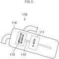
- the compressor 110 includes a drive shaft 112, an AC motor 111 that rotates the drive shaft 112, a compression mechanism 113 that compresses the refrigerant using rotation of the drive shaft 112, and a housing 114 that houses the drive shaft 112, the AC motor 111 and the compression mechanism 113.
- the AC motor 111 is specifically a three-phase AC permanent magnet synchronous motor. Lubricating oil is accumulated at portions in the housing 114 that may come in contact with the refrigerant.
- the compressor 110 is arranged in the railroad vehicle sideways, that is, arranged such that the drive shaft 112 inclines with respect to a vertical direction.
- the cooperating devices group 120 includes an outdoor heat exchanger 121 that functions as a condenser to condense the refrigerant compressed by the compressor 110, an expander 122 to expand the condensed refrigerant, and an indoor heat exchanger 123 that functions as an evaporator to evaporate the expanded refrigerant.
- the gaseous refrigerant resulting from the evaporation by the indoor heat exchanger 123 is compressed again by the compressor 110.
- the air conditioner 100 includes an outdoor fan 131 that facilitates heat exchange between the outdoor heat exchanger 121 and air of the outside of the vehicle, and an indoor fan 132 that facilitates heat exchange between the indoor heat exchanger 123 and air of the passenger compartment.
- the power conversion device 200 converts electric power supplied to the railroad vehicle from an overhead wire and distributes the converted electric power to the AC motor 111 of the compressor 110, the outdoor fan 131, and the indoor fan 132.
- the control device 300 controls the power conversion device 200 to thereby adjust air-conditioning performance of the air conditioner 100.
- the power conversion device 200 includes a compressor inverter 210 that supplies electric power to the AC motor 111 of the compressor 110.
- the compressor inverter 210 is an example of an inverter of the present disclosure.
- the control device 300 includes a compressor control device 310 that performs pulse width modulation (PWM) control of the compressor inverter 210.
- PWM pulse width modulation
- the compressor control device 310 is an example of an AC motor control device according to the present disclosure.
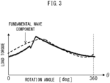
- FIG. 3 illustrates a load torque acting on the AC motor 111 of the compressor 110.
- the vertical axis indicates the load torque
- the horizontal axis indicates a rotation angle of a rotor of the AC motor 111.
- the load torque acting on the AC motor 111 has one peak during one rotation of the rotor.
- the presence of this peak causes fluctuations of a rotational velocity and a rotational acceleration of the rotor of the AC motor 111 that are hereinafter referred to as the "rotational velocity of the AC motor 111" and the “rotational acceleration of the AC motor 111, respectively.
- the frequency of the principal component of the fluctuations is equal to the number of rotations per one second of the rotor.
- the fluctuations of the rotational velocity and the rotational acceleration of the AC motor 111 cause vibration of the compressor 110.
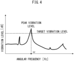
- FIG. 4 is a schematic diagram illustrating a vibration level of the compressor 110.
- the vertical axis indicates the vibration level, and the horizontal axis indicates an angular frequency.
- the vibration of the compressor 110 has an angular frequency component leading to a peak vibration level, which is hereinafter referred to as the "fundamental wave component".
- the angular frequency of the fundamental wave component is denoted as ⁇ .
- the broken line indicates the fundamental wave component.
- the compressor control device 310 illustrated in FIG. 1 performs torque compensation for adding, to a basic torque to be output by the AC motor 111, a torque compensation value with a phase opposite to that of the fundamental wave component of the aforementioned fluctuations.
- FIG. 5 illustrates waveforms of an output voltage output by the compressor inverter 210 to the AC motor 111 as a result of the aforementioned torque compensation.
- the vertical axis indicates the output voltage and the horizontal axis indicates time. The higher the rotational velocity of the AC motor 111, the higher the output voltage required for driving the AC motor 111.
- an instantaneous value of the output voltage may theoretically exceed a threshold limit value of the output voltage of the compressor inverter 210.
- this torque compensation causes an increase in an amplitude of the output voltage, leading to an increase in a possibility that a situation occurs where the instantaneous value of the output voltage theoretically exceeds the threshold limit value.
- the instantaneous value of the output voltage theoretically exceeding the threshold limit value causes occurrence of unstable operation of the AC motor 111.
- the compressor control device 310 has configuration for suppressing occurrence of unstable operation of the AC motor 111.
- the configuration of the compressor control device 310 is described in detail.
- the compressor control device 310 includes a current detector 311 that detects a current output by the compressor inverter 210 to the AC motor 111 and an estimator 312 to which a current detection value that is a result of the detection by the current detector 311 is input.
- the current detection value includes a value of current flowing in a coil of U-phase of the AC motor 111, a value of current flowing in a coil of V-phase of the AC motor 111, and a value of current flowing in a coil of W-phase of the AC motor 111.
- the estimator 312 calculates, using the current detection value, an estimated rotational velocity that is an estimate of the rotational velocity of the AC motor 111 and an estimated rotational acceleration that is an estimate of the rotational acceleration of the AC motor 111.
- the estimator 312 includes a proportional integral (PI) controller and an integrator that are series-connected.
- the compressor control device 310 includes a rotational velocity controller 313 to which the aforementioned estimated rotational velocity and a velocity command indicating a target rotational velocity of the AC motor 111 are input.
- the velocity command is generated by a host control device 320 included in the control device 300 illustrated in FIG. 1 .
- the compressor control device 310 may have the function of a velocity instructor that generates the velocity command.
- the velocity command is generated based on a temperature and other physical quantities in the passenger compartment that is the target of air-conditioning, user operation to switch the air-conditioning performance of the air conditioner 100, and the like.
- the rotational velocity controller 313 calculates, using the estimated rotational velocity, the basic torque to be output by the AC motor 111 that is required for causing the rotational velocity of the AC motor 111 to approach the target rotational velocity indicated by the velocity command.
- the rotational velocity controller 313 outputs a basic torque command indicating this basic torque.
- the rotational velocity controller 313 includes a PI controller.
- the compressor control device 310 includes a torque compensator 314 to which the aforementioned estimated rotational acceleration is input.
- the torque compensator 314 calculates, using the estimated rotational acceleration, the torque compensation value that is a compensation value for the aforementioned basic torque that is required for suppressing the fluctuation of the rotational velocity of the AC motor 111.
- the torque compensator 314 outputs a torque compensation command indicating this torque compensation value.
- the compressor control device 310 includes an adder 316 that adds, to the basic torque indicated by the aforementioned basic torque command, the limit-processed torque compensation value indicated by the limit-processed torque compensation command.
- the limit-processed torque compensation value is an AC signal and can alternate between positive and negative values.
- a value obtained by adding to the basic torque the limit-processed torque compensation value with a positive or negative sign is defined as the synthetic torque.
- the adder 316 outputs a synthetic torque command indicating the synthetic torque.
- the compressor control device 310 includes a voltage instructor 317 that outputs a voltage command indicating a voltage required for outputting the synthetic torque indicated by the aforementioned synthetic torque command.
- the voltage command is output to the compressor inverter 210 that supplies electric power to the AC motor 111.
- the compressor inverter 210 outputs, to the AC motor 111, a voltage in accordance with the voltage command.
- the torque compensation value indicated by the torque compensation command is an AC value that changes over time.
- the compensation limiter 315 limits an amplitude of the torque compensation value to be lower than or equal to a predetermined upper limit value while maintaining an average value of the torque compensation value.
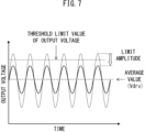
- FIG. 7 illustrates a waveform of the output voltage of the compressor inverter 210 in the case where the amplitude of the torque compensation value is limited through the limitation processing.
- the AC waveform indicated by the broken line of FIG. 7 indicates the output voltage in the case where the limitation processing is not executed.
- the amplitude of the output voltage of the compressor inverter 210 is limited while the average value of the output voltage is maintained. This configuration enables avoiding occurrence of a situation where the instantaneous value of the output voltage theoretically exceeds the aforementioned threshold limit value, thereby preventing occurrence of unstable operation of the AC motor 111.
- the average value of the output voltage is small as compared to the case where the rotational velocity of the AC motor 111 is high. That is, the case where the rotational velocity of the AC motor 111 is low leads to a large deviation of the average value of the output voltage from the aforementioned threshold limit value as compared to the case where the rotational velocity of the AC motor 111 is high.
- a small amount is sufficient as an amount by which the amplitude of the torque compensation value is limited through the limitation processing.
- the compensation limiter 315 employs, as the upper limit value of the amplitude of the torque compensation value, a value depending on the rotational velocity of the AC motor 111, more specifically, the target rotational velocity indicated by the velocity command illustrated in FIG. 6 .
- FIG. 8 illustrates details of the dependence of the upper limit value on the value of the target rotational velocity.
- the upper limit value for a value of the target rotational velocity within a first rotational velocity range which is hereinafter referred to as the "first upper limit value”
- first upper limit value is defined to be smaller than the upper limit value for a value of the target rotational velocity within a second rotational velocity range indicating the rotational velocity lower than the first rotational velocity range, which is hereinafter referred to as the "second upper limit value”.
- the average value of the output voltage has a large deviation from the aforementioned threshold limit value as compared to the case where the value of the target rotational velocity is within the first rotational velocity range. For this reason, a value larger than the first upper limit value is sufficient as the second upper limit value.
- the average value of the output voltage of the compressor inverter 210 has a smaller deviation from the aforementioned threshold limit value as compared to the case where the value of the target rotational velocity is within the second rotational velocity range. Therefore, to impose a large limitation to the amplitude of the output voltage of the compressor inverter 210, the first upper limit value is defined to be smaller than the second upper limit value.
- each of the first upper limit value and the second upper limit value is a constant that is independent of the target rotational velocity.
- the first rotational velocity range and the second rotational velocity range are contiguous on the horizontal axis illustrated in FIG. 8 , that is, a rotational velocity axis indicating the rotational velocity.
- An end point P1 of the first rotational velocity range that is closer to the second rotational velocity range indicates the rotational velocity when the output voltage of the compressor inverter 210 reaches a value between 60% and 90%, more specifically, 80%, of the aforementioned threshold limit value.
- a torque T output by the AC motor 111 is expressed by Formula (1) below using a d-axis current Id that is the d-axis component of the current supplied to the AC motor 111, and a q-axis current Iq that is the q-axis component of the current supplied to the AC motor 111.
- T Pm ⁇ ⁇ f ⁇ Iq ⁇ Pm ⁇ Lq ⁇ Ld ⁇ Id ⁇ Iq
- Pm is the number of pole pairs of the AC motor 111
- ⁇ f is an induced voltage constant of the AC motor 111
- Ld is the d-axis component of the inductance of the AC motor 111
- Lq is the q-axis component of the inductance of the AC motor 111.
- the second term on the right side of Formula (1) represents a reluctance torque. If the reluctance torque is ignored as small, the torque T can be deemed as proportional to the q-axis current Iq. Therefore, explanation equivalent to explanation of limitation of the torque compensation value performed by the compensation limiter 315 can be provided by explanation of the limitation of current.
- I_mar expressed by Formula (2) below is defined.
- the second upper limit value is defined as a value satisfying the condition I_mar > 0.
- I _ mar I _ lim 2 ⁇ I _ drv 2 0.5
- the output voltage of the compressor inverter 210 is expressed by Formula (3) below using a d-axis voltage Vd that is the d-axis component of the voltage supplied to the AC motor 111, and a q-axis voltage Vq that is the q-axis component of the voltage supplied to the AC motor 111.
- Output Voltage Vd 2 + Vq 2 0.5
- Vd R ⁇ Id + s ⁇ Ld ⁇ Id ⁇ ⁇ ⁇ Lq ⁇ Iq
- Vq R ⁇ Iq + s ⁇ Lq ⁇ Iq + ⁇ ⁇ Ld ⁇ Id + ⁇ f
- R is the winding resistance of the AC motor 111
- s is the differential operator expressed in Laplace transform
- ⁇ is the angular frequency of the fundamental wave component of the load torque illustrated in FIG. 3 or an integer multiple thereof.
- the first term on the right side of Formula (7) is canceled or reduced by the compensation of the fluctuation performed by cooperation of the torque compensator 314, the compensation limiter 315, and the adder 316.
- the output of the torque of the DC component corresponding to the second term on the right side of Formula (7) is achieved through the basic torque command.
- the q-axis current Iq required for the AC motor 111 to output the torque expressed in Formula (7) is expressed by Formula (8) below using Formula (1).
- the d-axis current Id is assumed to be sufficiently small.
- Iq TL _ ac / Pm / ⁇ f ⁇ cos ⁇ t + TL _ dc / Pm / ⁇ f
- the amplitude of the first term on the right side of Formula (8) is limited while the average value expressed by the second term on the right side of Formula (8) is maintained.
- Vdrv A value of the voltage corresponding to the second term on the right side of equation (8) is taken to be Vdrv.
- Vdrv is expressed, by substituting the second term on the right side of Formula (8) into Formula (6), by Formula (9) below.
- Vdrv ⁇ ⁇ Lq ⁇ TL _ dc / Pm / ⁇ f 2 + R ⁇ TL _ dc / Pm / ⁇ f + ⁇ ⁇ ⁇ f 2 0.5
- the first upper limit value is defined as a value satisfying the condition that a value of an amplitude of a voltage corresponding to an amplitude of the first term on the right side of Formula (8) is within the range of a difference between the threshold limit value of the output voltage of the compressor inverter 210 and the Vdrv expressed by Formula (9).
- the original amplitude of the torque compensation value may be less than the first upper limit value or the second upper limit value.
- " can match the amplitude of the fundamental wave component of the load torque "
- limit-processed torque compensation value indicated by the limit-processed torque compensation command illustrated in FIG. 6 encompasses not only the torque compensation value with the amplitude reduced in the limitation processing but also the torque compensation value with an amplitude that is not reduced in the limitation processing due to an original amplitude that is less than the first upper limit value or the second upper limit value.
- the limit-processed torque compensation value is added to the basic torque indicated by the basic torque command, the fluctuation of the rotational velocity of the AC motor 111 can be suppressed.
- the first upper limit value that is the upper limit value for the amplitude of the torque compensation value for cases where the target rotational velocity is high is defined to be smaller than the second upper limit value that is the upper limit value for cases where the target rotational velocity is small.
- This configuration decreases the possibility that a situation occurs where the output voltage theoretically exceeds the threshold limit value in response to the rotational velocity of the AC motor 111 being high.
- suppression of occurrence of unstable operation of the AC motor 111 when the rotational velocity is high can be achieved.
- FIG. 8 illustrates an example of configuration in which the upper limit value changes in a stepwise manner in accordance with the increase in the target rotational velocity.
- the dependence of the upper limit value on the target rotational velocity is not limited to the example illustrated in FIG. 8 .
- another example of the dependence of the upper limit value on the target rotational velocity is described.
- a third rotational velocity range intervenes between the first rotational velocity range for which the first upper limit value is defined and the second rotational velocity range for which the second upper limit value is defined.
- the upper limit value is taken to be a variable value having a linear variation characteristic of approaching the first upper limit value from the second upper limit value with approach from an end point Q1 of the third rotational velocity range that is closer to the second rotational velocity range toward another end point Q2 of the third rotational velocity range that is closer to the first rotational velocity range.
- a large change in the output torque of the AC motor 111 is less likely to occur upon shifting of the target rotational velocity of the AC motor 111 from one of the first range and the second rotational velocity range to the other range. This contributes to stabilization of the operation of the AC motor 111 and long working time of the AC motor 111.
- FIG. 1 illustrates the compressor control device 310 as an example of the AC motor control device according to the present disclosure
- the target of control of the AC motor control device according to the present disclosure is not limited to the AC motor 111 of the compressor 110.
Landscapes
- Engineering & Computer Science (AREA)
- Power Engineering (AREA)
- Mechanical Engineering (AREA)
- General Engineering & Computer Science (AREA)
- Physics & Mathematics (AREA)
- Thermal Sciences (AREA)
- Control Of Ac Motors In General (AREA)
Abstract
Description
- The present disclosure relates to an alternating-current (AC) motor control device and an air conditioning device.
- As disclosed in
Patent Literature 1, an AC motor control device is known that has a function for suppressing a fluctuation of a rotational velocity of an AC motor control device. A periodically-varying load torque acts on the AC motor. The AC motor control device includes a compensator that outputs, to an inverter for driving the AC motor, a compensation signal for suppressing a fluctuation of the rotational velocity, and a limiter that limits a compensation amount indicated by the compensation signal in order to reduce an amount of power consumption of the AC motor. - Patent Literature 1: Unexamined
Japanese Patent Application Publication No. 2006-180605 -
Patent Literature 1 is silent on a relationship between a degree of limitation to the aforementioned compensation amount and the rotational velocity of the AC motor. In the case where the rotational velocity of the AC motor is high, the AC motor may possibly operate unstably even with limitation of the compensation amount by the limiter. - An objective of the present disclosure is to provide an AC motor control device that can suppress a fluctuation of a rotational velocity of an AC motor and that can suppress occurrence of unstable operation of the AC motor when the rotational velocity is high, and to provide an air conditioning device that includes this AC motor control device.
- An AC motor control device according to the present disclosure includes:
- an estimator to calculate an estimated rotational velocity that is an estimate of a rotational velocity of an AC motor and an estimated rotational acceleration that is an estimate of a rotational acceleration of the AC motor;
- a rotational velocity controller to calculate, using the estimated rotational velocity, a basic torque to be output by the AC motor that is required for causing the rotational velocity of the AC motor to approach the target rotational velocity indicated by a velocity command, and output a basic torque command indicating the calculated basic torque;
- a torque compensator to calculate, using the estimated rotational acceleration, a torque compensation value that is a compensation value for the basic torque that is required for suppressing a fluctuation of the rotational velocity of the AC motor, and output a torque compensation command indicating the calculated torque compensation value;
- a compensation limiter to execute limitation processing for limiting the torque compensation value indicated by the torque compensation command, and output a limit-processed torque compensation command indicating a limit-processed torque compensation value obtained by the execution of the limitation processing on the torque compensation command;
- an adder to add, to the basic torque indicated by the basic torque command, the limit-processed torque compensation value indicated by the limit-processed torque compensation command, and output a synthetic torque command indicating a synthetic torque obtained by the addition; and
- a voltage instructor to output, to an inverter to supply electric power to the AC motor, a voltage command indicating a voltage required for outputting the synthetic torque indicated by the synthetic torque command, in which
- in the limitation processing, the compensation limiter limits an amplitude of the torque compensation value that changes over time to be lower than or equal to a predetermined upper limit value,
- the upper limit value depends on a value of the target rotational velocity, and
- a first upper limit value that is the upper limit value for a value of the target rotational velocity within a first rotational velocity range is defined to be smaller than a second upper limit value that is the upper limit value for a value of the target rotational velocity within a second rotational velocity range indicating the rotational velocity lower than the first rotational velocity range.
- The aforementioned configuration enables suppressing a fluctuation of the rotational velocity of the AC motor and suppressing occurrence of unstable operation of the AC motor when the rotational velocity is high.
-
-
FIG. 1 is a schematic diagram illustrating configuration of a railroad vehicle air conditioning apparatus according toEmbodiment 1; -
FIG. 2 is a schematic diagram illustrating configuration of a compressor according toEmbodiment 1; -
FIG. 3 is a graph illustrating a load torque acting on an AC motor of the compressor according toEmbodiment 1; -
FIG. 4 is a graph illustrating a vibration level of the compressor according toEmbodiment 1; -
FIG. 5 is a graph illustrating an output voltage of a compressor inverter according toEmbodiment 1; -
FIG. 6 is a schematic diagram illustrating configuration of a compressor control device according toEmbodiment 1; -
FIG. 7 is a graph illustrating an output voltage of a compressor inverter when limitation processing according toEmbodiment 1 is executed; -
FIG. 8 is a graph illustrating a relationship between upper limit values of an amplitude and a target rotational velocity according toEmbodiment 1; and -
FIG. 9 is a graph illustrating a relationship between upper limit values of an amplitude and a target rotational velocity according to Embodiment 2. - Hereinafter, railroad vehicle air conditioning apparatuses according to embodiments are described with reference to the drawings. In the drawings, the same reference signs denote the same or corresponding components.
- As illustrated in
FIG. 1 , a railroad vehicle air conditioning apparatus 400 according to the present embodiment includes anair conditioner 100 that performs air-conditioning of a passenger compartment of a railroad vehicle using a refrigeration cycle, apower conversion device 200 that supplies to theair conditioner 100 electric power necessary for the air-conditioning, and acontrol device 300 that controls thepower conversion device 200. Theair conditioner 100, thepower conversion device 200, and thecontrol device 300 are mounted on the railroad vehicle. The railroad vehicle air conditioning apparatus 400 is an example of an air conditioning device according to the present disclosure. - The
air conditioner 100 includes acompressor 110 that compresses refrigerant and acooperating devices group 120 that is included in, together with thecompressor 110, a refrigeration cycle for circulation therethrough of the refrigerant. - As illustrated in
FIG. 2 , thecompressor 110 includes adrive shaft 112, anAC motor 111 that rotates thedrive shaft 112, acompression mechanism 113 that compresses the refrigerant using rotation of thedrive shaft 112, and ahousing 114 that houses thedrive shaft 112, theAC motor 111 and thecompression mechanism 113. - The
AC motor 111 is specifically a three-phase AC permanent magnet synchronous motor. Lubricating oil is accumulated at portions in thehousing 114 that may come in contact with the refrigerant. Thecompressor 110 is arranged in the railroad vehicle sideways, that is, arranged such that thedrive shaft 112 inclines with respect to a vertical direction. - Again with reference to
FIG. 1 , thecooperating devices group 120 includes anoutdoor heat exchanger 121 that functions as a condenser to condense the refrigerant compressed by thecompressor 110, anexpander 122 to expand the condensed refrigerant, and anindoor heat exchanger 123 that functions as an evaporator to evaporate the expanded refrigerant. The gaseous refrigerant resulting from the evaporation by theindoor heat exchanger 123 is compressed again by thecompressor 110. - The
air conditioner 100 includes anoutdoor fan 131 that facilitates heat exchange between theoutdoor heat exchanger 121 and air of the outside of the vehicle, and anindoor fan 132 that facilitates heat exchange between theindoor heat exchanger 123 and air of the passenger compartment. - The
power conversion device 200 converts electric power supplied to the railroad vehicle from an overhead wire and distributes the converted electric power to theAC motor 111 of thecompressor 110, theoutdoor fan 131, and theindoor fan 132. Thecontrol device 300 controls thepower conversion device 200 to thereby adjust air-conditioning performance of theair conditioner 100. - The
power conversion device 200 includes acompressor inverter 210 that supplies electric power to theAC motor 111 of thecompressor 110. Thecompressor inverter 210 is an example of an inverter of the present disclosure. Thecontrol device 300 includes acompressor control device 310 that performs pulse width modulation (PWM) control of thecompressor inverter 210. Thecompressor control device 310 is an example of an AC motor control device according to the present disclosure. - Hereinafter, the problem to be solved by the present embodiment is described.
-
FIG. 3 illustrates a load torque acting on theAC motor 111 of thecompressor 110. The vertical axis indicates the load torque, and the horizontal axis indicates a rotation angle of a rotor of theAC motor 111. As illustrated with the solid line inFIG. 3 , the load torque acting on theAC motor 111 has one peak during one rotation of the rotor. - The presence of this peak causes fluctuations of a rotational velocity and a rotational acceleration of the rotor of the
AC motor 111 that are hereinafter referred to as the "rotational velocity of theAC motor 111" and the "rotational acceleration of theAC motor 111, respectively. The frequency of the principal component of the fluctuations is equal to the number of rotations per one second of the rotor. The fluctuations of the rotational velocity and the rotational acceleration of theAC motor 111 cause vibration of thecompressor 110. -
FIG. 4 is a schematic diagram illustrating a vibration level of thecompressor 110. The vertical axis indicates the vibration level, and the horizontal axis indicates an angular frequency. As illustrated inFIG. 4 , the vibration of thecompressor 110 has an angular frequency component leading to a peak vibration level, which is hereinafter referred to as the "fundamental wave component". InFIG. 4 , the angular frequency of the fundamental wave component is denoted as ω. InFIG. 3 referenced above, the broken line indicates the fundamental wave component. - The vibration of the
compressor 110 caused by the fluctuations of theAC motor 111 causes generation of noise and malfunction of thecompressor 110. For this reason, keeping the above peak vibration level below the target vibration level illustrated inFIG. 4 is desirable. - Thus, in order to reduce the aforementioned fluctuations that cause vibration of the
compressor 110, thecompressor control device 310 illustrated inFIG. 1 performs torque compensation for adding, to a basic torque to be output by theAC motor 111, a torque compensation value with a phase opposite to that of the fundamental wave component of the aforementioned fluctuations. - However, simply performing the torque compensation may possibly result in unstable operation of the
AC motor 111. This point is described below. -
FIG. 5 illustrates waveforms of an output voltage output by thecompressor inverter 210 to theAC motor 111 as a result of the aforementioned torque compensation. The vertical axis indicates the output voltage and the horizontal axis indicates time. The higher the rotational velocity of theAC motor 111, the higher the output voltage required for driving theAC motor 111. - Due to this, at a high rotational velocity of the
AC motor 111, an instantaneous value of the output voltage may theoretically exceed a threshold limit value of the output voltage of thecompressor inverter 210. In particular, in the case of performing the torque compensation, this torque compensation causes an increase in an amplitude of the output voltage, leading to an increase in a possibility that a situation occurs where the instantaneous value of the output voltage theoretically exceeds the threshold limit value. The instantaneous value of the output voltage theoretically exceeding the threshold limit value causes occurrence of unstable operation of theAC motor 111. - To solve the above-explained problems, the
compressor control device 310 according to the present embodiment has configuration for suppressing occurrence of unstable operation of theAC motor 111. Hereinafter, the configuration of thecompressor control device 310 is described in detail. - As illustrated in
FIG. 6 , thecompressor control device 310 includes a current detector 311 that detects a current output by thecompressor inverter 210 to theAC motor 111 and anestimator 312 to which a current detection value that is a result of the detection by the current detector 311 is input. - The current detection value includes a value of current flowing in a coil of U-phase of the
AC motor 111, a value of current flowing in a coil of V-phase of theAC motor 111, and a value of current flowing in a coil of W-phase of theAC motor 111. - The
estimator 312 calculates, using the current detection value, an estimated rotational velocity that is an estimate of the rotational velocity of theAC motor 111 and an estimated rotational acceleration that is an estimate of the rotational acceleration of theAC motor 111. Theestimator 312 includes a proportional integral (PI) controller and an integrator that are series-connected. - Additionally, the
compressor control device 310 includes arotational velocity controller 313 to which the aforementioned estimated rotational velocity and a velocity command indicating a target rotational velocity of theAC motor 111 are input. - The velocity command is generated by a
host control device 320 included in thecontrol device 300 illustrated inFIG. 1 . As another example, thecompressor control device 310 may have the function of a velocity instructor that generates the velocity command. The velocity command is generated based on a temperature and other physical quantities in the passenger compartment that is the target of air-conditioning, user operation to switch the air-conditioning performance of theair conditioner 100, and the like. - The
rotational velocity controller 313 calculates, using the estimated rotational velocity, the basic torque to be output by theAC motor 111 that is required for causing the rotational velocity of theAC motor 111 to approach the target rotational velocity indicated by the velocity command. Therotational velocity controller 313 outputs a basic torque command indicating this basic torque. Therotational velocity controller 313 includes a PI controller. - Additionally, the
compressor control device 310 includes atorque compensator 314 to which the aforementioned estimated rotational acceleration is input. Thetorque compensator 314 calculates, using the estimated rotational acceleration, the torque compensation value that is a compensation value for the aforementioned basic torque that is required for suppressing the fluctuation of the rotational velocity of theAC motor 111. Thetorque compensator 314 outputs a torque compensation command indicating this torque compensation value. - Additionally, the
compressor control device 310 includes acompensation limiter 315 to which the aforementioned torque compensation command is input. Thecompensation limiter 315 executes limitation processing for limiting the torque compensation value indicated by the torque compensation command. Thecompensation limiter 315 outputs a limit-processed torque compensation command indicating a limit-processed torque compensation value obtained by execution of the limitation processing on the torque compensation command. - Additionally, the
compressor control device 310 includes anadder 316 that adds, to the basic torque indicated by the aforementioned basic torque command, the limit-processed torque compensation value indicated by the limit-processed torque compensation command. - The limit-processed torque compensation value is an AC signal and can alternate between positive and negative values. A value obtained by adding to the basic torque the limit-processed torque compensation value with a positive or negative sign is defined as the synthetic torque. The
adder 316 outputs a synthetic torque command indicating the synthetic torque. - Additionally, the
compressor control device 310 includes avoltage instructor 317 that outputs a voltage command indicating a voltage required for outputting the synthetic torque indicated by the aforementioned synthetic torque command. The voltage command is output to thecompressor inverter 210 that supplies electric power to theAC motor 111. Thecompressor inverter 210 outputs, to theAC motor 111, a voltage in accordance with the voltage command. - Hereinafter, an operation of the
compensation limiter 315 for preventing occurrence of unstable operation of theAC motor 111 is described. - The torque compensation value indicated by the torque compensation command is an AC value that changes over time. In the aforementioned limitation processing, the
compensation limiter 315 limits an amplitude of the torque compensation value to be lower than or equal to a predetermined upper limit value while maintaining an average value of the torque compensation value. -
FIG. 7 illustrates a waveform of the output voltage of thecompressor inverter 210 in the case where the amplitude of the torque compensation value is limited through the limitation processing. The AC waveform indicated by the broken line ofFIG. 7 indicates the output voltage in the case where the limitation processing is not executed. - Due to the limitation of the amplitude of the torque compensation value to be lower than or equal to the upper limit value in the limitation processing, as illustrated in
FIG. 7 , the amplitude of the output voltage of thecompressor inverter 210 is limited while the average value of the output voltage is maintained. This configuration enables avoiding occurrence of a situation where the instantaneous value of the output voltage theoretically exceeds the aforementioned threshold limit value, thereby preventing occurrence of unstable operation of theAC motor 111. - Here, as illustrated in
FIG. 5 , in the case where the rotational velocity of theAC motor 111 is low, the average value of the output voltage is small as compared to the case where the rotational velocity of theAC motor 111 is high. That is, the case where the rotational velocity of theAC motor 111 is low leads to a large deviation of the average value of the output voltage from the aforementioned threshold limit value as compared to the case where the rotational velocity of theAC motor 111 is high. Thus, in the case where the rotational velocity of theAC motor 111 is low, a small amount is sufficient as an amount by which the amplitude of the torque compensation value is limited through the limitation processing. - Therefore, the
compensation limiter 315 employs, as the upper limit value of the amplitude of the torque compensation value, a value depending on the rotational velocity of theAC motor 111, more specifically, the target rotational velocity indicated by the velocity command illustrated inFIG. 6 . -
FIG. 8 illustrates details of the dependence of the upper limit value on the value of the target rotational velocity. The upper limit value for a value of the target rotational velocity within a first rotational velocity range, which is hereinafter referred to as the "first upper limit value", is defined to be smaller than the upper limit value for a value of the target rotational velocity within a second rotational velocity range indicating the rotational velocity lower than the first rotational velocity range, which is hereinafter referred to as the "second upper limit value". - In the case where the value of the target rotational velocity is within the second rotational velocity range, the average value of the output voltage has a large deviation from the aforementioned threshold limit value as compared to the case where the value of the target rotational velocity is within the first rotational velocity range. For this reason, a value larger than the first upper limit value is sufficient as the second upper limit value.
- Conversely, in the case where the value of the target rotational velocity is within the first rotational velocity range, the average value of the output voltage of the
compressor inverter 210 has a smaller deviation from the aforementioned threshold limit value as compared to the case where the value of the target rotational velocity is within the second rotational velocity range. Therefore, to impose a large limitation to the amplitude of the output voltage of thecompressor inverter 210, the first upper limit value is defined to be smaller than the second upper limit value. - In the present embodiment, each of the first upper limit value and the second upper limit value is a constant that is independent of the target rotational velocity. The first rotational velocity range and the second rotational velocity range are contiguous on the horizontal axis illustrated in
FIG. 8 , that is, a rotational velocity axis indicating the rotational velocity. - An end point P1 of the first rotational velocity range that is closer to the second rotational velocity range indicates the rotational velocity when the output voltage of the
compressor inverter 210 reaches a value between 60% and 90%, more specifically, 80%, of the aforementioned threshold limit value. - Hereinafter, a condition to be satisfied by the second upper limit value is first described in terms of the current supplied to the
AC motor 111. - A torque T output by the
AC motor 111 is expressed by Formula (1) below using a d-axis current Id that is the d-axis component of the current supplied to theAC motor 111, and a q-axis current Iq that is the q-axis component of the current supplied to theAC motor 111.
- In Formula (1), Pm is the number of pole pairs of the
AC motor 111, φf is an induced voltage constant of theAC motor 111, Ld is the d-axis component of the inductance of theAC motor 111, and Lq is the q-axis component of the inductance of theAC motor 111. - The second term on the right side of Formula (1) represents a reluctance torque. If the reluctance torque is ignored as small, the torque T can be deemed as proportional to the q-axis current Iq. Therefore, explanation equivalent to explanation of limitation of the torque compensation value performed by the
compensation limiter 315 can be provided by explanation of the limitation of current. - Thus, using the value of current I_lim corresponding to the aforementioned threshold limit value of the output voltage and the current I_drv required for outputting the aforementioned synthetic torque, I_mar expressed by Formula (2) below is defined. The second upper limit value is defined as a value satisfying the condition I_mar > 0.

- Next, a condition to be satisfied by the first upper limit value is described in terms of the current and voltage supplied to the
AC motor 111. - The output voltage of the
compressor inverter 210 is expressed by Formula (3) below using a d-axis voltage Vd that is the d-axis component of the voltage supplied to theAC motor 111, and a q-axis voltage Vq that is the q-axis component of the voltage supplied to theAC motor 111.
- Additionally, using the voltage equation, the d-axis voltage Vd is expressed by Formula (4) below, and the q-axis voltage Vq is expressed by Formula (5) below.


- In Formulas (4) and (5), "R" is the winding resistance of the
AC motor 111, "s" is the differential operator expressed in Laplace transform, and "ω" is the angular frequency of the fundamental wave component of the load torque illustrated inFIG. 3 or an integer multiple thereof. - For simplicity, the d-axis current Id is taken to be sufficiently small. Additionally, to focus on the steady state, the second term on the right-hand side in Formulas (4) and (5) including the differential operator "s" is ignored. Using Formulas (3), (4), and (5), the output voltage is expressed by Formula (6) below.

- The fundamental wave component of the load torque illustrated in
FIG. 3 is expressed by Formula (7) below.
- The first term on the right side of Formula (7) is canceled or reduced by the compensation of the fluctuation performed by cooperation of the
torque compensator 314, thecompensation limiter 315, and theadder 316. The output of the torque of the DC component corresponding to the second term on the right side of Formula (7) is achieved through the basic torque command. - The q-axis current Iq required for the
AC motor 111 to output the torque expressed in Formula (7) is expressed by Formula (8) below using Formula (1). For simplicity, the d-axis current Id is assumed to be sufficiently small.
- In the limitation processing executed by the
compensation limiter 315, due to the limitation of the amplitude of the torque compensation value, the amplitude of the first term on the right side of Formula (8) is limited while the average value expressed by the second term on the right side of Formula (8) is maintained. - A value of the voltage corresponding to the second term on the right side of equation (8) is taken to be Vdrv. Vdrv is expressed, by substituting the second term on the right side of Formula (8) into Formula (6), by Formula (9) below.

- The first upper limit value is defined as a value satisfying the condition that a value of an amplitude of a voltage corresponding to an amplitude of the first term on the right side of Formula (8) is within the range of a difference between the threshold limit value of the output voltage of the
compressor inverter 210 and the Vdrv expressed by Formula (9). - Next, an acceleration level of rotation of the
AC motor 111 is described. - An amplitude of the fundamental wave component of the load torque illustrated in
FIG. 3 is taken to be |TL_ac|, and an amplitude of the synthetic torque indicated by the synthetic torque command illustrated inFIG. 6 is taken to be |Tm_ac|. The acceleration level of rotation of theAC motor 111 is expressed by Formula (10) below. Jm represents the moment of inertia of the rotor of theAC motor 111.
- In the case where the amplitude of the torque compensation value is limited through the aforementioned limitation processing, the amplitude of the synthetic torque "|Tm_ac|" does not match the amplitude of the fundamental wave component of the load torque "|TL_ac|". Due to this, the acceleration level expressed in Formula (10) is not zero.
- However, since the torque compensation value with the amplitude limited through the limitation processing is added to the basic torque, the amplitude of the synthetic torque "|Tm_ac|" approaches the amplitude of the fundamental wave component of the load torque "|TL_ac|". As a result, the acceleration level expressed in Formula (10) is suppressed. This enables suppression of the fluctuation of the rotational velocity of the
AC motor 111, resulting in suppression of generation of vibration and noise of thecompressor 110. - Note that the original amplitude of the torque compensation value may be less than the first upper limit value or the second upper limit value. In this case, since the amplitude of the torque compensation value is not limited through the aforementioned limitation processing, the amplitude of the synthetic torque "|Tm_ac|" can match the amplitude of the fundamental wave component of the load torque "|TL_ac|".
- The concept of the "limit-processed torque compensation value" indicated by the limit-processed torque compensation command illustrated in
FIG. 6 encompasses not only the torque compensation value with the amplitude reduced in the limitation processing but also the torque compensation value with an amplitude that is not reduced in the limitation processing due to an original amplitude that is less than the first upper limit value or the second upper limit value. - As described above, according to the present embodiment, since the limit-processed torque compensation value is added to the basic torque indicated by the basic torque command, the fluctuation of the rotational velocity of the
AC motor 111 can be suppressed. - Additionally, as illustrated in
FIG. 8 , the first upper limit value that is the upper limit value for the amplitude of the torque compensation value for cases where the target rotational velocity is high is defined to be smaller than the second upper limit value that is the upper limit value for cases where the target rotational velocity is small. This configuration decreases the possibility that a situation occurs where the output voltage theoretically exceeds the threshold limit value in response to the rotational velocity of theAC motor 111 being high. Thus, suppression of occurrence of unstable operation of theAC motor 111 when the rotational velocity is high can be achieved. -
FIG. 8 illustrates an example of configuration in which the upper limit value changes in a stepwise manner in accordance with the increase in the target rotational velocity. The dependence of the upper limit value on the target rotational velocity is not limited to the example illustrated inFIG. 8 . Hereinafter, another example of the dependence of the upper limit value on the target rotational velocity is described. - As illustrated in
FIG. 9 , in the present embodiment, a third rotational velocity range intervenes between the first rotational velocity range for which the first upper limit value is defined and the second rotational velocity range for which the second upper limit value is defined. - In the third rotational velocity range, the upper limit value is taken to be a variable value having a linear variation characteristic of approaching the first upper limit value from the second upper limit value with approach from an end point Q1 of the third rotational velocity range that is closer to the second rotational velocity range toward another end point Q2 of the third rotational velocity range that is closer to the first rotational velocity range.
- According to the present embodiment, a large change in the output torque of the
AC motor 111 is less likely to occur upon shifting of the target rotational velocity of theAC motor 111 from one of the first range and the second rotational velocity range to the other range. This contributes to stabilization of the operation of theAC motor 111 and long working time of theAC motor 111. - Embodiments 1 and 2 are described above. Although
FIG. 1 illustrates thecompressor control device 310 as an example of the AC motor control device according to the present disclosure, the target of control of the AC motor control device according to the present disclosure is not limited to theAC motor 111 of thecompressor 110. - The target of control of the AC motor control device according to the present disclosure may be an AC motor included in the
outdoor fan 131 or may be an AC motor included in theindoor fan 132. Furthermore, the target of control of the AC motor control device according to the present disclosure may be an AC motor included in a device other than theair conditioner 100. - The foregoing describes some example embodiments for explanatory purposes. Although the foregoing discussion has presented specific embodiments, persons skilled in the art will recognize that changes may be made in form and detail without departing from the broader spirit and scope of the invention. Accordingly, the specification and drawings are to be regarded in an illustrative rather than a restrictive sense. This detailed description, therefore, is not to be taken in a limiting sense, and the scope of the invention is defined only by the included claims, along with the full range of equivalents to which such claims are entitled.
-
- 100
- Air conditioner
- 110
- Compressor
- 111
- AC motor
- 112
- Drive shaft
- 113
- Compression mechanism
- 114
- Housing
- 120
- Cooperating devices group
- 121
- Outdoor heat exchanger
- 122
- Expander
- 123
- Indoor heat exchanger
- 131
- Outdoor fan
- 132
- Indoor fan
- 200
- Power conversion device
- 210
- Compressor inverter (inverter)
- 300
- Control device
- 310
- Compressor control device (AC motor control device)
- 311
- Current detector
- 312
- Estimator
- 313
- Rotational velocity controller
- 314
- Torque compensator
- 315
- Compensation limiter
- 316
- Adder
- 317
- Voltage instructor
- 320
- Host control device
- 400
- Railroad vehicle air conditioning apparatus (air conditioning device)
Claims (7)
- An AC motor control device, comprising:an estimator to calculate an estimated rotational velocity that is an estimate of a rotational velocity of an AC motor and an estimated rotational acceleration that is an estimate of a rotational acceleration of the AC motor;a rotational velocity controller to calculate, using the estimated rotational velocity, a basic torque to be output by the AC motor that is required for causing the rotational velocity of the AC motor to approach the target rotational velocity indicated by a velocity command, and output a basic torque command indicating the calculated basic torque;a torque compensator to calculate, using the estimated rotational acceleration, a torque compensation value that is a compensation value for the basic torque that is required for suppressing a fluctuation of the rotational velocity of the AC motor, and output a torque compensation command indicating the calculated torque compensation value;a compensation limiter to execute limitation processing for limiting the torque compensation value indicated by the torque compensation command, and output a limit-processed torque compensation command indicating a limit-processed torque compensation value obtained by the execution of the limitation processing on the torque compensation command;an adder to add, to the basic torque indicated by the basic torque command, the limit-processed torque compensation value indicated by the limit-processed torque compensation command, and output a synthetic torque command indicating a synthetic torque obtained by the addition; anda voltage instructor to output, to an inverter to supply electric power to the AC motor, a voltage command indicating a voltage required for outputting the synthetic torque indicated by the synthetic torque command, whereinin the limitation processing, the compensation limiter limits an amplitude of the torque compensation value that changes over time to be lower than or equal to a predetermined upper limit value,the upper limit value depends on a value of the target rotational velocity, anda first upper limit value that is the upper limit value for a value of the target rotational velocity within a first rotational velocity range is defined to be smaller than a second upper limit value that is the upper limit value for a value of the target rotational velocity within a second rotational velocity range indicating the rotational velocity lower than the first rotational velocity range.
- The AC motor control device according to claim 1, whereineach of the first upper limit value and the second upper limit value is a constant,a third rotational velocity range intervenes between the first rotational velocity range and the second rotational velocity range, andin the third rotational velocity range, the upper limit value is taken to be a variable value having a linear variation characteristic of approaching the first upper limit value from the second upper limit value with approach from an end point of the third rotational velocity range that is closer to the second rotational velocity range toward another end point of the third rotational velocity range that is closer to the first rotational velocity range.
- The AC motor control device according to claim 1, whereineach of the first upper limit value and the second upper limit value is a constant, andthe first rotational velocity range and the second rotational velocity range are contiguous.
- The AC motor control device according to any one of claims 1 to 3, wherein an end point of the first rotational velocity range that is closer to the second rotational velocity range indicates the rotational velocity when an output voltage that is output by the inverter to the AC motor reaches a value between 60% and 90% of a threshold limit value of an output voltage outputtable by the inverter.
- The AC motor control device according to any one of claims 1 to 4, wherein, due to the limitation of the amplitude of the torque compensation value to be lower than or equal to the upper limit value in the limitation processing, an amplitude of an output voltage that is output by the inverter to the AC motor is limited while an average value of the output voltage is maintained.
- An air conditioning device, comprising:the AC motor control device according to any one of claims 1 to 5;a compressor including the AC motor and to compress refrigerant through circulation of the AC motor; anda cooperating devices group included in, together with the compressor, a refrigeration cycle for circulation therethrough of the refrigerant.
- The air conditioning device according to claim 6, wherein the air conditioning device is mountable on a railroad vehicle and is configured to perform air-conditioning of a passenger compartment of the railroad vehicle using the refrigeration cycle.
Applications Claiming Priority (1)
| Application Number | Priority Date | Filing Date | Title |
|---|---|---|---|
| PCT/JP2022/031327 WO2024038574A1 (en) | 2022-08-19 | 2022-08-19 | Ac electric motor control device and air conditioning device |
Publications (2)
| Publication Number | Publication Date |
|---|---|
| EP4576560A1 true EP4576560A1 (en) | 2025-06-25 |
| EP4576560A4 EP4576560A4 (en) | 2025-10-15 |
Family
ID=89941723
Family Applications (1)
| Application Number | Title | Priority Date | Filing Date |
|---|---|---|---|
| EP22955748.3A Pending EP4576560A4 (en) | 2022-08-19 | 2022-08-19 | AC ELECTRIC MOTOR CONTROL DEVICE AND AIR CONDITIONING DEVICE |
Country Status (3)
| Country | Link |
|---|---|
| EP (1) | EP4576560A4 (en) |
| JP (1) | JP7696510B2 (en) |
| WO (1) | WO2024038574A1 (en) |
Family Cites Families (7)
| Publication number | Priority date | Publication date | Assignee | Title |
|---|---|---|---|---|
| JP4596906B2 (en) | 2004-12-22 | 2010-12-15 | 日立アプライアンス株式会社 | Electric motor control device |
| US9160271B2 (en) * | 2012-01-18 | 2015-10-13 | Mitsubishi Electric Corporation | Power conversion device |
| JP5462906B2 (en) * | 2012-04-16 | 2014-04-02 | 山洋電気株式会社 | Motor control device |
| WO2017212794A1 (en) * | 2016-06-08 | 2017-12-14 | 三菱電機株式会社 | Speed estimation apparatus for ac motor, driving apparatus for ac motor, refrigerant compressor, and freezing cycle apparatus |
| EP3605829B1 (en) * | 2017-03-31 | 2021-09-08 | Kabushiki Kaisha Yaskawa Denki | Electric motor control device, compressor, and electric motor control method |
| JP7166468B2 (en) * | 2019-09-24 | 2022-11-07 | 三菱電機株式会社 | Motor drive device and refrigeration cycle application equipment |
| JP7213196B2 (en) * | 2020-02-28 | 2023-01-26 | 株式会社 日立パワーデバイス | MOTOR DRIVE DEVICE, OUTDOOR UNIT OF AIR CONDITIONER USING THE SAME, MOTOR DRIVE CONTROL METHOD |
-
2022
- 2022-08-19 JP JP2024541369A patent/JP7696510B2/en active Active
- 2022-08-19 WO PCT/JP2022/031327 patent/WO2024038574A1/en not_active Ceased
- 2022-08-19 EP EP22955748.3A patent/EP4576560A4/en active Pending
Also Published As
| Publication number | Publication date |
|---|---|
| EP4576560A4 (en) | 2025-10-15 |
| JP7696510B2 (en) | 2025-06-20 |
| JPWO2024038574A1 (en) | 2024-02-22 |
| WO2024038574A1 (en) | 2024-02-22 |
Similar Documents
| Publication | Publication Date | Title |
|---|---|---|
| JP2004060457A (en) | Compressor internal condition estimation device and air conditioner | |
| JP6456650B2 (en) | Motor control device, compressor, air conditioner and program | |
| JP5116620B2 (en) | Electric motor drive device and refrigeration air conditioner | |
| US20210067066A1 (en) | Drive system, fluid utilization apparatus, and air conditioner | |
| CN106208887B (en) | No electrolytic capacitor motor driven systems and its control method, device | |
| JPWO2020234971A1 (en) | Motor drive, compressor drive and refrigeration cycle device | |
| KR101458170B1 (en) | Motor drive device and compressor using the same | |
| JP2018014854A (en) | Motor drive device and refrigerating and air-conditioning equipment using the same | |
| JP7566175B2 (en) | Power conversion devices, motor drive devices and refrigeration cycle application devices | |
| JPWO2020170379A1 (en) | Motor drive device and refrigeration cycle applicable equipment | |
| US12018673B2 (en) | Compressor control method | |
| WO2023073870A1 (en) | Power conversion device, motor driving device, and refrigeration-cycle application instrument | |
| EP4576560A1 (en) | Ac electric motor control device and air conditioning device | |
| JP5200569B2 (en) | Inverter device | |
| Hu et al. | Linear quadratic extended state observer based load torque compensation for PMSM in a single rotor compressor | |
| US20240405694A1 (en) | Power converting apparatus, motor drive unit, and refrigeration cycle-incorporating device | |
| JP2018182975A (en) | Compressor motor drive | |
| JP7595807B2 (en) | Motor drive device and refrigeration cycle device | |
| JP5604991B2 (en) | MOTOR DRIVE DEVICE AND ELECTRIC DEVICE USING THE SAME | |
| JP2020139461A (en) | Electric compressor | |
| US10608561B2 (en) | Control device of AC motor | |
| WO2023176873A1 (en) | State determination device, motor drive system, freezing system, fan system, and state determination method | |
| JP6286669B2 (en) | Inverter control device | |
| JP2011193585A (en) | Motor drive and electric equipment using the same | |
| TWI662782B (en) | Motor driving device, refrigeration cycle device including the same, and motor driving method |
Legal Events
| Date | Code | Title | Description |
|---|---|---|---|
| STAA | Information on the status of an ep patent application or granted ep patent |
Free format text: STATUS: THE INTERNATIONAL PUBLICATION HAS BEEN MADE |
|
| PUAI | Public reference made under article 153(3) epc to a published international application that has entered the european phase |
Free format text: ORIGINAL CODE: 0009012 |
|
| STAA | Information on the status of an ep patent application or granted ep patent |
Free format text: STATUS: REQUEST FOR EXAMINATION WAS MADE |
|
| 17P | Request for examination filed |
Effective date: 20250212 |
|
| AK | Designated contracting states |
Kind code of ref document: A1 Designated state(s): AL AT BE BG CH CY CZ DE DK EE ES FI FR GB GR HR HU IE IS IT LI LT LU LV MC MK MT NL NO PL PT RO RS SE SI SK SM TR |
|
| REG | Reference to a national code |
Ref country code: DE Ref legal event code: R079 Free format text: PREVIOUS MAIN CLASS: H02P0021220000 Ipc: H02P0006180000 |
|
| A4 | Supplementary search report drawn up and despatched |
Effective date: 20250916 |
|
| RIC1 | Information provided on ipc code assigned before grant |
Ipc: H02P 6/18 20160101AFI20250910BHEP Ipc: H02P 6/10 20060101ALI20250910BHEP Ipc: H02P 21/22 20160101ALI20250910BHEP Ipc: H02P 27/06 20060101ALI20250910BHEP Ipc: H02P 23/04 20060101ALI20250910BHEP Ipc: H02P 29/50 20160101ALI20250910BHEP Ipc: B60H 1/32 20060101ALI20250910BHEP Ipc: B60L 15/00 20060101ALI20250910BHEP Ipc: F04B 49/00 20060101ALI20250910BHEP |
|
| DAV | Request for validation of the european patent (deleted) | ||
| DAX | Request for extension of the european patent (deleted) |