EP4576519A1 - Cooling system - Google Patents
Cooling system Download PDFInfo
- Publication number
- EP4576519A1 EP4576519A1 EP23891479.0A EP23891479A EP4576519A1 EP 4576519 A1 EP4576519 A1 EP 4576519A1 EP 23891479 A EP23891479 A EP 23891479A EP 4576519 A1 EP4576519 A1 EP 4576519A1
- Authority
- EP
- European Patent Office
- Prior art keywords
- cooling
- coolant
- heat exchanger
- unit
- electronic circuit
- Prior art date
- Legal status (The legal status is an assumption and is not a legal conclusion. Google has not performed a legal analysis and makes no representation as to the accuracy of the status listed.)
- Pending
Links
Images





Classifications
-
- H—ELECTRICITY
- H02—GENERATION; CONVERSION OR DISTRIBUTION OF ELECTRIC POWER
- H02K—DYNAMO-ELECTRIC MACHINES
- H02K11/00—Structural association of dynamo-electric machines with electric components or with devices for shielding, monitoring or protection
- H02K11/30—Structural association with control circuits or drive circuits
- H02K11/33—Drive circuits, e.g. power electronics
-
- B—PERFORMING OPERATIONS; TRANSPORTING
- B60—VEHICLES IN GENERAL
- B60H—ARRANGEMENTS OF HEATING, COOLING, VENTILATING OR OTHER AIR-TREATING DEVICES SPECIALLY ADAPTED FOR PASSENGER OR GOODS SPACES OF VEHICLES
- B60H1/00—Heating, cooling or ventilating devices
- B60H1/00271—HVAC devices specially adapted for particular vehicle parts or components and being connected to the vehicle HVAC unit
- B60H1/00278—HVAC devices specially adapted for particular vehicle parts or components and being connected to the vehicle HVAC unit for the battery
-
- B—PERFORMING OPERATIONS; TRANSPORTING
- B60—VEHICLES IN GENERAL
- B60H—ARRANGEMENTS OF HEATING, COOLING, VENTILATING OR OTHER AIR-TREATING DEVICES SPECIALLY ADAPTED FOR PASSENGER OR GOODS SPACES OF VEHICLES
- B60H1/00—Heating, cooling or ventilating devices
- B60H1/00642—Control systems or circuits; Control members or indication devices for heating, cooling or ventilating devices
- B60H1/00814—Control systems or circuits characterised by their output, for controlling particular components of the heating, cooling or ventilating installation
- B60H1/00878—Control systems or circuits characterised by their output, for controlling particular components of the heating, cooling or ventilating installation the components being temperature regulating devices
- B60H1/00899—Controlling the flow of liquid in a heat pump system
- B60H1/00921—Controlling the flow of liquid in a heat pump system where the flow direction of the refrigerant does not change and there is an extra subcondenser, e.g. in an air duct
-
- B—PERFORMING OPERATIONS; TRANSPORTING
- B60—VEHICLES IN GENERAL
- B60K—ARRANGEMENT OR MOUNTING OF PROPULSION UNITS OR OF TRANSMISSIONS IN VEHICLES; ARRANGEMENT OR MOUNTING OF PLURAL DIVERSE PRIME-MOVERS IN VEHICLES; AUXILIARY DRIVES FOR VEHICLES; INSTRUMENTATION OR DASHBOARDS FOR VEHICLES; ARRANGEMENTS IN CONNECTION WITH COOLING, AIR INTAKE, GAS EXHAUST OR FUEL SUPPLY OF PROPULSION UNITS IN VEHICLES
- B60K1/00—Arrangement or mounting of electrical propulsion units
-
- B—PERFORMING OPERATIONS; TRANSPORTING
- B60—VEHICLES IN GENERAL
- B60K—ARRANGEMENT OR MOUNTING OF PROPULSION UNITS OR OF TRANSMISSIONS IN VEHICLES; ARRANGEMENT OR MOUNTING OF PLURAL DIVERSE PRIME-MOVERS IN VEHICLES; AUXILIARY DRIVES FOR VEHICLES; INSTRUMENTATION OR DASHBOARDS FOR VEHICLES; ARRANGEMENTS IN CONNECTION WITH COOLING, AIR INTAKE, GAS EXHAUST OR FUEL SUPPLY OF PROPULSION UNITS IN VEHICLES
- B60K11/00—Arrangement in connection with cooling of propulsion units
- B60K11/02—Arrangement in connection with cooling of propulsion units with liquid cooling
-
- B—PERFORMING OPERATIONS; TRANSPORTING
- B60—VEHICLES IN GENERAL
- B60K—ARRANGEMENT OR MOUNTING OF PROPULSION UNITS OR OF TRANSMISSIONS IN VEHICLES; ARRANGEMENT OR MOUNTING OF PLURAL DIVERSE PRIME-MOVERS IN VEHICLES; AUXILIARY DRIVES FOR VEHICLES; INSTRUMENTATION OR DASHBOARDS FOR VEHICLES; ARRANGEMENTS IN CONNECTION WITH COOLING, AIR INTAKE, GAS EXHAUST OR FUEL SUPPLY OF PROPULSION UNITS IN VEHICLES
- B60K11/00—Arrangement in connection with cooling of propulsion units
- B60K11/02—Arrangement in connection with cooling of propulsion units with liquid cooling
- B60K11/04—Arrangement or mounting of radiators, radiator shutters, or radiator blinds
-
- B—PERFORMING OPERATIONS; TRANSPORTING
- B60—VEHICLES IN GENERAL
- B60L—PROPULSION OF ELECTRICALLY-PROPELLED VEHICLES; SUPPLYING ELECTRIC POWER FOR AUXILIARY EQUIPMENT OF ELECTRICALLY-PROPELLED VEHICLES; ELECTRODYNAMIC BRAKE SYSTEMS FOR VEHICLES IN GENERAL; MAGNETIC SUSPENSION OR LEVITATION FOR VEHICLES; MONITORING OPERATING VARIABLES OF ELECTRICALLY-PROPELLED VEHICLES; ELECTRIC SAFETY DEVICES FOR ELECTRICALLY-PROPELLED VEHICLES
- B60L1/00—Supplying electric power to auxiliary equipment of vehicles
- B60L1/02—Supplying electric power to auxiliary equipment of vehicles to electric heating circuits
-
- F—MECHANICAL ENGINEERING; LIGHTING; HEATING; WEAPONS; BLASTING
- F01—MACHINES OR ENGINES IN GENERAL; ENGINE PLANTS IN GENERAL; STEAM ENGINES
- F01P—COOLING OF MACHINES OR ENGINES IN GENERAL; COOLING OF INTERNAL-COMBUSTION ENGINES
- F01P11/00—Component parts, details, or accessories not provided for in, or of interest apart from, groups F01P1/00 - F01P9/00
- F01P11/04—Arrangements of liquid pipes or hoses
-
- F—MECHANICAL ENGINEERING; LIGHTING; HEATING; WEAPONS; BLASTING
- F01—MACHINES OR ENGINES IN GENERAL; ENGINE PLANTS IN GENERAL; STEAM ENGINES
- F01P—COOLING OF MACHINES OR ENGINES IN GENERAL; COOLING OF INTERNAL-COMBUSTION ENGINES
- F01P11/00—Component parts, details, or accessories not provided for in, or of interest apart from, groups F01P1/00 - F01P9/00
- F01P11/08—Arrangements of lubricant coolers
-
- F—MECHANICAL ENGINEERING; LIGHTING; HEATING; WEAPONS; BLASTING
- F01—MACHINES OR ENGINES IN GENERAL; ENGINE PLANTS IN GENERAL; STEAM ENGINES
- F01P—COOLING OF MACHINES OR ENGINES IN GENERAL; COOLING OF INTERNAL-COMBUSTION ENGINES
- F01P3/00—Liquid cooling
-
- F—MECHANICAL ENGINEERING; LIGHTING; HEATING; WEAPONS; BLASTING
- F01—MACHINES OR ENGINES IN GENERAL; ENGINE PLANTS IN GENERAL; STEAM ENGINES
- F01P—COOLING OF MACHINES OR ENGINES IN GENERAL; COOLING OF INTERNAL-COMBUSTION ENGINES
- F01P3/00—Liquid cooling
- F01P3/20—Cooling circuits not specific to a single part of engine or machine
-
- F—MECHANICAL ENGINEERING; LIGHTING; HEATING; WEAPONS; BLASTING
- F01—MACHINES OR ENGINES IN GENERAL; ENGINE PLANTS IN GENERAL; STEAM ENGINES
- F01P—COOLING OF MACHINES OR ENGINES IN GENERAL; COOLING OF INTERNAL-COMBUSTION ENGINES
- F01P3/00—Liquid cooling
- F01P3/22—Liquid cooling characterised by evaporation and condensation of coolant in closed cycles; characterised by the coolant reaching higher temperatures than normal atmospheric boiling-point
-
- F—MECHANICAL ENGINEERING; LIGHTING; HEATING; WEAPONS; BLASTING
- F01—MACHINES OR ENGINES IN GENERAL; ENGINE PLANTS IN GENERAL; STEAM ENGINES
- F01P—COOLING OF MACHINES OR ENGINES IN GENERAL; COOLING OF INTERNAL-COMBUSTION ENGINES
- F01P7/00—Controlling of coolant flow
- F01P7/14—Controlling of coolant flow the coolant being liquid
-
- F—MECHANICAL ENGINEERING; LIGHTING; HEATING; WEAPONS; BLASTING
- F25—REFRIGERATION OR COOLING; COMBINED HEATING AND REFRIGERATION SYSTEMS; HEAT PUMP SYSTEMS; MANUFACTURE OR STORAGE OF ICE; LIQUEFACTION SOLIDIFICATION OF GASES
- F25B—REFRIGERATION MACHINES, PLANTS OR SYSTEMS; COMBINED HEATING AND REFRIGERATION SYSTEMS; HEAT PUMP SYSTEMS
- F25B5/00—Compression machines, plants or systems, with several evaporator circuits, e.g. for varying refrigerating capacity
- F25B5/02—Compression machines, plants or systems, with several evaporator circuits, e.g. for varying refrigerating capacity arranged in parallel
-
- F—MECHANICAL ENGINEERING; LIGHTING; HEATING; WEAPONS; BLASTING
- F25—REFRIGERATION OR COOLING; COMBINED HEATING AND REFRIGERATION SYSTEMS; HEAT PUMP SYSTEMS; MANUFACTURE OR STORAGE OF ICE; LIQUEFACTION SOLIDIFICATION OF GASES
- F25B—REFRIGERATION MACHINES, PLANTS OR SYSTEMS; COMBINED HEATING AND REFRIGERATION SYSTEMS; HEAT PUMP SYSTEMS
- F25B6/00—Compression machines, plants or systems, with several condenser circuits
- F25B6/04—Compression machines, plants or systems, with several condenser circuits arranged in series
-
- H—ELECTRICITY
- H02—GENERATION; CONVERSION OR DISTRIBUTION OF ELECTRIC POWER
- H02K—DYNAMO-ELECTRIC MACHINES
- H02K9/00—Arrangements for cooling or ventilating
- H02K9/19—Arrangements for cooling or ventilating for machines with closed casing and closed-circuit cooling using a liquid cooling medium, e.g. oil
-
- B—PERFORMING OPERATIONS; TRANSPORTING
- B60—VEHICLES IN GENERAL
- B60H—ARRANGEMENTS OF HEATING, COOLING, VENTILATING OR OTHER AIR-TREATING DEVICES SPECIALLY ADAPTED FOR PASSENGER OR GOODS SPACES OF VEHICLES
- B60H1/00—Heating, cooling or ventilating devices
- B60H1/00271—HVAC devices specially adapted for particular vehicle parts or components and being connected to the vehicle HVAC unit
- B60H2001/00307—Component temperature regulation using a liquid flow
-
- B—PERFORMING OPERATIONS; TRANSPORTING
- B60—VEHICLES IN GENERAL
- B60K—ARRANGEMENT OR MOUNTING OF PROPULSION UNITS OR OF TRANSMISSIONS IN VEHICLES; ARRANGEMENT OR MOUNTING OF PLURAL DIVERSE PRIME-MOVERS IN VEHICLES; AUXILIARY DRIVES FOR VEHICLES; INSTRUMENTATION OR DASHBOARDS FOR VEHICLES; ARRANGEMENTS IN CONNECTION WITH COOLING, AIR INTAKE, GAS EXHAUST OR FUEL SUPPLY OF PROPULSION UNITS IN VEHICLES
- B60K1/00—Arrangement or mounting of electrical propulsion units
- B60K1/04—Arrangement or mounting of electrical propulsion units of the electric storage means for propulsion
-
- B—PERFORMING OPERATIONS; TRANSPORTING
- B60—VEHICLES IN GENERAL
- B60K—ARRANGEMENT OR MOUNTING OF PROPULSION UNITS OR OF TRANSMISSIONS IN VEHICLES; ARRANGEMENT OR MOUNTING OF PLURAL DIVERSE PRIME-MOVERS IN VEHICLES; AUXILIARY DRIVES FOR VEHICLES; INSTRUMENTATION OR DASHBOARDS FOR VEHICLES; ARRANGEMENTS IN CONNECTION WITH COOLING, AIR INTAKE, GAS EXHAUST OR FUEL SUPPLY OF PROPULSION UNITS IN VEHICLES
- B60K1/00—Arrangement or mounting of electrical propulsion units
- B60K2001/003—Arrangement or mounting of electrical propulsion units with means for cooling the electrical propulsion units
-
- B—PERFORMING OPERATIONS; TRANSPORTING
- B60—VEHICLES IN GENERAL
- B60K—ARRANGEMENT OR MOUNTING OF PROPULSION UNITS OR OF TRANSMISSIONS IN VEHICLES; ARRANGEMENT OR MOUNTING OF PLURAL DIVERSE PRIME-MOVERS IN VEHICLES; AUXILIARY DRIVES FOR VEHICLES; INSTRUMENTATION OR DASHBOARDS FOR VEHICLES; ARRANGEMENTS IN CONNECTION WITH COOLING, AIR INTAKE, GAS EXHAUST OR FUEL SUPPLY OF PROPULSION UNITS IN VEHICLES
- B60K1/00—Arrangement or mounting of electrical propulsion units
- B60K2001/003—Arrangement or mounting of electrical propulsion units with means for cooling the electrical propulsion units
- B60K2001/005—Arrangement or mounting of electrical propulsion units with means for cooling the electrical propulsion units the electric storage means
-
- B—PERFORMING OPERATIONS; TRANSPORTING
- B60—VEHICLES IN GENERAL
- B60K—ARRANGEMENT OR MOUNTING OF PROPULSION UNITS OR OF TRANSMISSIONS IN VEHICLES; ARRANGEMENT OR MOUNTING OF PLURAL DIVERSE PRIME-MOVERS IN VEHICLES; AUXILIARY DRIVES FOR VEHICLES; INSTRUMENTATION OR DASHBOARDS FOR VEHICLES; ARRANGEMENTS IN CONNECTION WITH COOLING, AIR INTAKE, GAS EXHAUST OR FUEL SUPPLY OF PROPULSION UNITS IN VEHICLES
- B60K1/00—Arrangement or mounting of electrical propulsion units
- B60K2001/003—Arrangement or mounting of electrical propulsion units with means for cooling the electrical propulsion units
- B60K2001/006—Arrangement or mounting of electrical propulsion units with means for cooling the electrical propulsion units the electric motors
-
- B—PERFORMING OPERATIONS; TRANSPORTING
- B60—VEHICLES IN GENERAL
- B60L—PROPULSION OF ELECTRICALLY-PROPELLED VEHICLES; SUPPLYING ELECTRIC POWER FOR AUXILIARY EQUIPMENT OF ELECTRICALLY-PROPELLED VEHICLES; ELECTRODYNAMIC BRAKE SYSTEMS FOR VEHICLES IN GENERAL; MAGNETIC SUSPENSION OR LEVITATION FOR VEHICLES; MONITORING OPERATING VARIABLES OF ELECTRICALLY-PROPELLED VEHICLES; ELECTRIC SAFETY DEVICES FOR ELECTRICALLY-PROPELLED VEHICLES
- B60L2220/00—Electrical machine types; Structures or applications thereof
- B60L2220/50—Structural details of electrical machines
-
- B—PERFORMING OPERATIONS; TRANSPORTING
- B60—VEHICLES IN GENERAL
- B60L—PROPULSION OF ELECTRICALLY-PROPELLED VEHICLES; SUPPLYING ELECTRIC POWER FOR AUXILIARY EQUIPMENT OF ELECTRICALLY-PROPELLED VEHICLES; ELECTRODYNAMIC BRAKE SYSTEMS FOR VEHICLES IN GENERAL; MAGNETIC SUSPENSION OR LEVITATION FOR VEHICLES; MONITORING OPERATING VARIABLES OF ELECTRICALLY-PROPELLED VEHICLES; ELECTRIC SAFETY DEVICES FOR ELECTRICALLY-PROPELLED VEHICLES
- B60L2240/00—Control parameters of input or output; Target parameters
- B60L2240/10—Vehicle control parameters
- B60L2240/36—Temperature of vehicle components or parts
-
- B—PERFORMING OPERATIONS; TRANSPORTING
- B60—VEHICLES IN GENERAL
- B60L—PROPULSION OF ELECTRICALLY-PROPELLED VEHICLES; SUPPLYING ELECTRIC POWER FOR AUXILIARY EQUIPMENT OF ELECTRICALLY-PROPELLED VEHICLES; ELECTRODYNAMIC BRAKE SYSTEMS FOR VEHICLES IN GENERAL; MAGNETIC SUSPENSION OR LEVITATION FOR VEHICLES; MONITORING OPERATING VARIABLES OF ELECTRICALLY-PROPELLED VEHICLES; ELECTRIC SAFETY DEVICES FOR ELECTRICALLY-PROPELLED VEHICLES
- B60L2240/00—Control parameters of input or output; Target parameters
- B60L2240/40—Drive Train control parameters
- B60L2240/42—Drive Train control parameters related to electric machines
- B60L2240/425—Temperature
-
- F—MECHANICAL ENGINEERING; LIGHTING; HEATING; WEAPONS; BLASTING
- F25—REFRIGERATION OR COOLING; COMBINED HEATING AND REFRIGERATION SYSTEMS; HEAT PUMP SYSTEMS; MANUFACTURE OR STORAGE OF ICE; LIQUEFACTION SOLIDIFICATION OF GASES
- F25B—REFRIGERATION MACHINES, PLANTS OR SYSTEMS; COMBINED HEATING AND REFRIGERATION SYSTEMS; HEAT PUMP SYSTEMS
- F25B2339/00—Details of evaporators; Details of condensers
- F25B2339/04—Details of condensers
- F25B2339/047—Water-cooled condensers
Definitions
- the present invention relates to a cooling system.
- an electric vehicle drive unit including at least an electric motor that transmits a drive rotational force to a traveling system of a vehicle (see, for example, Patent Document 1).
- This electric vehicle drive unit is downsized by integrally housing the electric motor and a gear unit into a housing, and is connected to a cooling system that exchanges heat between a coolant and oil circulating through the electric vehicle drive unit.
- the cooling system described in Patent Document 1 includes an inverter unit attached to the electric vehicle drive unit, and exchanges heat between the coolant circulating from the inverter unit to an oil cooler and the oil circulating through the electric vehicle drive unit.
- the oil cooler is attached to a lower part of a motor housing portion of the electric vehicle drive unit, and a cooling pipe is routed between the oil cooler and the inverter unit.
- Patent Document 1 Japanese Unexamined Patent Application Publication No. 2020-178485 ( JP 2020-178485 A )
- the cooling system includes: an integrated unit in which an electric vehicle drive unit including at least an electric motor configured to transmit a drive rotational force to a traveling system of a vehicle and an electronic circuit unit including at least an electronic circuit configured to drive the electric motor are integrated; a cooling channel through which a coolant circulates to the electronic circuit unit; and an oil channel that includes a heat exchanger configured to exchange heat with the coolant circulating through the cooling channel and through which oil circulates to the electric vehicle drive unit.
- the heat exchanger is disposed inside the integrated unit between the electric vehicle drive unit and the electronic circuit unit.
- the integrated unit in which the electric vehicle drive unit and the electronic circuit unit are integrated is provided. Therefore, downsizing can be achieved compared with a case where the electric vehicle drive unit and the electronic circuit unit are disposed separately.
- the heat exchanger that exchanges heat between the coolant and the oil the waste heat of the electric vehicle drive unit can be recovered by the coolant.
- the heat exchanger is disposed inside the integrated unit between the electric vehicle drive unit and the electronic circuit unit.
- heat can be exchanged between the oil and the coolant inside the integrated unit, thereby improving the heat recovery rate.
- the length of the pipe exposed from the heat exchanger to the outside can be reduced.
- the cooling system can suppress the dissipation of the waste heat of the electric vehicle drive unit from the cooling pipe, thereby achieving downsizing and efficient heat management.
- An electric vehicle includes an electric vehicle drive unit that drives wheels with a current supplied from a battery.
- Examples of the electric vehicle include vehicles including a motor as a traveling drive source (hybrid electric vehicle (HEV), plug-in hybrid electric vehicle (PHEV), battery electric vehicle (BEV), fuel cell electric vehicle (FCEV), etc.).
- HEV hybrid electric vehicle
- PHEV plug-in hybrid electric vehicle
- BEV battery electric vehicle
- FCEV fuel cell electric vehicle
- the electric vehicle includes an integrated unit 1 shown in FIGS. 1 and 2 .
- the integrated unit 1 includes an electric vehicle drive unit 2 (hereinafter referred to as "vehicle drive unit 2"), an electronic circuit unit 3, and a cooling module 4.
- vehicle drive unit 2 an electric vehicle drive unit 2
- electronic circuit unit 3 an electronic circuit unit 3
- the cooling module 4 is disposed to adjoin the electronic circuit unit 3.
- a chiller 86, a water-cooled condenser 81, an accumulator 82, and auxiliary devices such as valves and pumps described later and portions of a cooling channel B and a refrigerant channel D are modularized as the cooling module 4 and housed in the unit case 5.
- a cooling system A in the present embodiment described below is an example in which only the vehicle drive unit 2 and the electronic circuit unit 3 are housed in the unit case 5, but the shape and structure of the integrated unit 1 are not particularly limited.
- the traveling direction of the vehicle (vehicle front-to-rear direction) may be referred to as an X direction
- the width direction of the vehicle (vehicle left-to-right direction)
- the height direction of the vehicle may be referred to as a Z direction.
- the front side in the traveling direction of the vehicle may be referred to as an X1 side
- the rear side in the traveling direction may be referred to as an X2 side
- the left side in the vehicle width direction may be referred to as a Y1 side
- the right side in the vehicle width direction may be referred to as a Y2 side.
- the vehicle drive unit 2 includes at least an electric motor 21 that transmits a drive rotational force to a traveling system of the vehicle.
- the vehicle drive unit 2 includes the electric motor 21, gears 22 including a speed reducing mechanism, etc.
- the electronic circuit unit 3 includes at least electronic circuits 31 for driving the electric motor 21.
- the electronic circuit unit 3 is housed in the unit case 5 to form a power supply module 100, and a plurality of electronic components constituting on-board chargers (OBCs) 32 (an example of a voltage conversion circuit) and an inverter (INV) 33 as the electronic circuits 31 is mounted on a substrate 35.
- OBCs on-board chargers
- ISV inverter
- the cooling system A includes the integrated unit 1 in which the vehicle drive unit 2 and the electronic circuit unit 3 are integrated, the cooling channel B through which the coolant circulates to the electronic circuit unit 3 (power supply module 100), an oil channel C through which oil circulates to the vehicle drive unit 2, and the refrigerant channel D through which a refrigerant for heating and cooling a vehicle cabin circulates.
- a coolant such as an antifreeze liquid mainly containing ethylene glycol etc. or a long-life coolant or a coolant such as insulating oil flows through the cooling channel B.
- a refrigerant such as hydrofluorocarbon (HFC) flows through the refrigerant channel D.
- HFC hydrofluorocarbon
- the electronic circuit unit 3 is disposed on an upper part of the unit case 5 and fixed to a support S.
- the vehicle drive unit 2 is disposed below the support S.
- the disposition of the vehicle drive unit 2 and the electronic circuit unit 3 is not limited to this.
- the vehicle drive unit 2 and the electronic circuit unit 3 may be arranged along the X direction or the Y direction.
- the vehicle drive unit 2 may be disposed on the upper side and the electronic circuit unit 3 may be disposed on the lower side.
- the cooling module 4 is disposed to adjoin the electronic circuit unit 3.
- a refrigerant manifold 4a is disposed on the upper part of the unit case 5, and the water-cooled condenser 81 is disposed on the side of the refrigerant manifold 4a.
- a valve unit 6 in which a water pump 51 and a valve 52 (see FIG. 4 ) disposed in the cooling channel B are integrated is disposed on a side surface 5A of the unit case 5 below the water-cooled condenser 81.
- the cooling channel B will be described.
- the cooling channel B is a channel shown above the electric motor 21 in FIGS. 3 and 4 .
- the cooling channel B includes the valve unit 6, the power supply module 100, an oil cooler 62 (an example of a heat exchanger) described later, the water-cooled condenser 81, a radiator 53, etc. provided midway along the channel.
- the cooling channel B includes a first channel 54 extending from the water-cooled condenser 81 to the radiator 53, and the second channel 55 extending from the radiator 53 to the water-cooled condenser 81.
- the electronic circuit unit 3 has part of the second channel 55 of the cooling channel B as an internal channel of the cooling plate 36. Part of the cooling channel B is disposed inside the unit case 5.
- the coolant circulates through the power supply module 100 (electronic circuit unit 3), the oil cooler 62, the water-cooled condenser 81, and the radiator 53 in this order.
- the valve 52 (an example of a three-way valve) switchable between a first state in which the coolant flows through the radiator 53 and a second state in which the flow of the coolant into the radiator 53 is blocked and the coolant is diverted is disposed in the first channel 54 through which the coolant is supplied to the radiator 53.
- the cooling channel B can be switched by the valve 52 between a channel 56 in which the coolant passes through the radiator 53 and joins the second channel 55 and a channel 57 in which the coolant flows without passing through the radiator 53 and joins the second channel 55.
- the water pump 51 is disposed downstream of the valve 52 and the radiator 53.
- the cooling channel B also includes a channel 58 extending from the electronic circuit unit 3 to the oil cooler 62, and a channel 59 extending from the oil cooler 62 to the water-cooled condenser 81.
- the oil channel C is a channel shown below the electronic circuit unit 3 in FIGS. 3 and 4 .
- the oil channel C includes an oil pump 61 and the oil cooler 62 (an example of the heat exchanger) provided midway along the channel. Oil is supplied to the electric motor 21 etc. and circulates through the vehicle drive unit 2.
- the oil cooler 62 is located downstream of the power supply module 100 (electronic circuit unit 3) in the cooling channel B, and exchanges heat with the coolant circulating through the cooling channel B.
- the refrigerant channel D is a channel shown on the right side in FIG. 4 , and the refrigerant for heating and cooling circulates therethrough.
- the refrigerant channel D includes a heating channel 71 through which a refrigerant for heating the vehicle cabin circulates, a cooling channel 72 through which a refrigerant for cooling the vehicle cabin circulates, and a battery cooling channel 73 through which the refrigerant circulates to cool a battery 87 mounted on the vehicle.
- the heating channel 71 includes the water-cooled condenser 81, the accumulator 82, a compressor 83, and a cabin condenser 84 (heating condenser) disposed in this order to constitute a heat pump as a whole.
- the refrigerant channel D includes the water-cooled condenser 81 provided midway along the channel to exchange heat with the coolant circulating through the cooling channel B.
- the water-cooled condenser 81 is located downstream of the oil cooler 62 in the cooling channel B, and exchanges heat with the coolant circulating through the cooling channel B.
- an on-off valve 91 is disposed in a channel 74 between the water-cooled condenser 81 and the accumulator 82, and a first expansion valve 92 is disposed in a channel 76 between the cabin condenser 84 and the water-cooled condenser 81.
- the compressor 83, the cabin condenser 84, and a channel 75 passing through them are disposed outside the unit case 5.
- the cooling channel 72 is constituted by a channel 77 that branches from the channel 74 on the upstream side of the on-off valve 91.
- the channel 77 includes a second expansion valve 93 and an evaporator 85 provided in this order midway along the channel, and joins the channel 74 on the downstream side of the on-off valve 91. That is, when the second expansion valve 93 is driven with the on-off valve 91 closed, the refrigerant flows through the channel 77 and the evaporator 85 cools the vehicle cabin.
- the evaporator 85 in the cooling channel 72 is disposed outside the unit case 5.
- the battery cooling channel 73 is constituted by a channel 78 that branches from the channel 77 of the cooling channel 72 on the upstream side of the second expansion valve 93.
- the channel 78 includes a third expansion valve 94 and the chiller 86 provided in this order midway along the channel, and joins the channel 77 on the downstream side of the evaporator 85. That is, when the third expansion valve 94 is driven with the on-off valve 91 closed, the refrigerant flows through the channel 78, and the chiller 86 exchanges heat between the refrigerant and a coolant circulating through a cooling circuit 79.
- the on-off valve 91, the first expansion valve 92, the second expansion valve 93, and the third expansion valve 94 be modularized and integrated with the cooling module 4, and be housed inside the cooling module 4.
- the battery cooling channel 73 is structured such that the chiller 86 is disposed in the cooling circuit 79 through which the coolant circulates between the chiller 86 and the battery 87.
- a water pump 88 is disposed in the cooling circuit 79 midway along the channel.
- the battery 87 in the battery cooling channel 73 is disposed, for example, in a space under the floor of the vehicle cabin that is located outside and rearward of the unit case 5.
- the integrated unit 1 in which the vehicle drive unit 2 and the electronic circuit unit 3 (power supply module 100) are integrated is provided. Therefore, downsizing can be achieved compared with a case where the vehicle drive unit 2 and the electronic circuit unit 3 (power supply module 100) are disposed separately.
- the oil cooler 62 that exchanges heat between the coolant and the oil, waste heat of the vehicle drive unit 2 can be recovered by the coolant.
- the oil cooler 62 is disposed inside the integrated unit 1 between the vehicle drive unit 2 and the electronic circuit unit 3 (power supply module 100).
- the oil cooler 62 is disposed, for example, below the electronic circuit unit 3 and is provided downstream of the second channel 55 formed inside the cooling plate 36.
- heat can be exchanged between the oil circulating through the oil channel C and the coolant circulating through the cooling channel B inside the integrated unit 1, thereby improving the heat recovery rate.
- the length of the pipe exposed from the oil cooler 62 to the outside can be reduced.
- the cooling system A of the present embodiment can suppress dissipation of the waste heat of the vehicle drive unit 2 from the cooling pipe, thereby achieving downsizing and efficient heat management.
- the electronic circuits 31 of the electronic circuit unit 3 include the inverter (INV) 33 that controls the current to be supplied from the battery 87 to the electric motor 21, and the on-board chargers (OBCs) 32 that control the voltage for charging the battery 87.
- the inverter 33 is disposed on the upper part of the electronic circuit unit 3
- the on-board chargers 32 are disposed on the upper and lower parts of the electronic circuit unit 3.
- the cooling system A can further be downsized.
- the disposition of the electronic circuits 31 mounted on the electronic circuit unit 3 shown in FIG. 3 is an example, and the disposition of the electronic circuits 31 may be changed as appropriate.
- the oil cooler 62 is formed in a box shape with, for example, an upper surface 62A near the electronic circuits 31 and a lower surface 62B near the electric motor 21.
- a coolant inlet 63 through which the coolant flows in from the top is provided on the upper surface 62A
- a coolant outlet 64 that extends toward the side of the oil cooler 62 and through which the coolant flows out is provided on the lower surface 62B.
- the coolant outlet 64 includes a first portion 64A that is bent from the lower surface 62B toward the upper surface 62A, and a second portion 64B that is continuous with the first portion 64A and extends along the upper surface 62A.
- the coolant can flow out from the side of the oil cooler 62 to the outside of the electronic circuit unit 3 (power supply module 100).
- the channel 59 that is continuous with the water-cooled condenser 81 from the coolant outlet 64 of the oil cooler 62 is formed through the side surface 5A of the unit case 5 and is disposed along the outer side of the valve unit 6.
- the coolant pipe connected to the oil cooler 62 does not occupy a large area in the height direction of the oil cooler 62, and the integrated unit 1 can be made compact even when the oil cooler 62 is disposed between the vehicle drive unit 2 and the electronic circuit unit 3 (power supply module 100).
- the oil cooler 62 includes, individually on the lower surface 62B, an oil inlet 65 through which the oil flows in, and an oil outlet 66 through which the oil flows out.
- the integrated unit 1 can be made compact even when the oil cooler 62 is disposed between the vehicle drive unit 2 and the electronic circuit unit 3 (power supply module 100).
- the oil outlet 66 of the oil cooler 62 is connected to a supply portion 67 that supplies the oil toward the electric motor 21.
- the oil flowing out from the supply portion 67 flows out from the lower surface 62B of the oil cooler 62 toward the electric motor 21. In this way, the oil can flow out from the lower surface 62B of the oil cooler 62 toward the electric motor 21.
- the first embodiment illustrates the example in which the channel between the oil cooler 62 and the water-cooled condenser 81 is exposed to the outside.
- the valve unit 6 (cooling manifold) in which part of the cooling channel B is formed inside the housing may be attached integrally to the integrated unit 1.
- the water-cooled condenser 81 and the valve unit 6 are integrated, and the channel 59 extending from the oil cooler 62 to the water-cooled condenser 81 and part of the first channel 54 extending from the water-cooled condenser 81 to the valve 52 and the water pump 51 are provided inside the valve unit 6 to form a manifold.
- the integrated unit 1 in which the vehicle drive unit 2 and the electronic circuit unit 3 (power supply module 100) are integrated is provided. Therefore, downsizing can be achieved compared with a case where the vehicle drive unit 2 and the electronic circuit unit 3 (power supply module 100) are disposed separately.
- the oil cooler 62 that exchanges heat between the coolant and the oil and the water-cooled condenser 81 that exchanges heat between the coolant and the refrigerant are provided. That is, the temperature of the coolant changes in the oil cooler 62 by utilizing the waste heat of the vehicle drive unit 2 and in the water-cooled condenser 81 by utilizing the heat of the refrigerant.
- valve unit 6 in which part of the cooling channel B is formed inside the housing is attached integrally to the integrated unit 1. That is, part of the cooling channel B through which the coolant circulates to exchange heat with both the oil and the refrigerant is integrated with the integrated unit 1.
- the length of the cooling pipe routed in the cooling channel B can be reduced, and the dissipation of the waste heat of the vehicle drive unit 2 from the cooling pipe can be suppressed.
- the cooling system A of the present embodiment can also achieve downsizing and efficient heat management.
- the valve unit 6 in which part of the cooling channel B is formed inside the housing is disposed on the side surface of the electronic circuit unit 3 (power supply module 100).
- the cooling pipe of the cooling channel B extending from the oil cooler 62 disposed near the vehicle drive unit 2 adjacent to the electronic circuit unit 3 can be designed so as not to be exposed to the outside. As a result, the dissipation of the waste heat of the vehicle drive unit 2 from the cooling pipe of the cooling channel B can be suppressed.
- the water-cooled condenser 81 is attached integrally to the valve unit 6, and the cooling channel B that communicates with the water-cooled condenser 81 is formed inside the valve unit 6.
- the cooling pipe of the cooling channel B can be designed so as not to be exposed to the outside when heat is exchanged between the coolant circulating through the cooling channel B and the refrigerant circulating through the refrigerant channel D. As a result, the dissipation of the waste heat of the vehicle drive unit 2 from the cooling pipe of the cooling channel B can be suppressed.
- the oil cooler 62 is disposed on the side surface 5A of the unit case 5, and the water-cooled condenser 81, the valve unit 6, and the oil cooler 62 are attached integrally to the integrated unit 1.
- the channels of the cooling channel B that communicate with the water-cooled condenser 81 and the oil cooler 62 are formed Inside the valve unit 6.
- the channel 58 extending from the electronic circuit unit 3 (power supply module 100) to the oil cooler 62, the channel 59 extending from the oil cooler 62 to the water-cooled condenser 81, and part of the first channel 54 extending from the water-cooled condenser 81 to the valve 52 and the water pump 51 are provided inside the valve unit 6 to form a manifold.
- the cooling pipe of the cooling channel B can be designed so as not to be exposed to the outside when heat is exchanged between the coolant and the oil. As a result, the dissipation of the waste heat of the vehicle drive unit 2 from the cooling pipe of the cooling channel B can be suppressed.
- the integrated unit 1 has a first space 11 in which the vehicle drive unit 2 is disposed, a second space 12 in which the electronic circuit unit 3 is disposed, and a partition wall S1 that separates the first space 11 and the second space 12. That is, the integrated unit 1 is partitioned into the first space 11 at the bottom and the second space 12 at the top by the partition wall S1.
- the electronic circuit unit 3 is disposed on the upper part of the unit case 5 and fixed to the partition wall S1.
- the vehicle drive unit 2 is disposed below the partition wall S1.
- the cooling module 4 is disposed to adjoin the electronic circuit unit 3.
- the refrigerant manifold 4a is disposed on the upper part of the unit case 5, and the water-cooled condenser 81 is attached to the side surface 5A (an example of an outer surface) of the unit case 5.
- the integrated unit 1 includes the cooling module 4 in which the refrigerant manifold 4a including the refrigerant channel D through which the refrigerant flows and the water-cooled condenser 81 are integrated.
- the refrigerant manifold 4a is located above the water-cooled condenser 81.
- the valve unit 6 is disposed on the side surface 5A of the unit case 5.
- the water-cooled condenser 81 is located on the left side (Y1 direction side) of the front side (X1 direction side), and the valve unit 6 is located on the right side (Y2 direction side) of the front side (X1 direction side).
- the second space 12 of the unit case 5 houses the electronic circuit unit 3 and the cooling plate 36 for cooling the power supply module 100.
- the cooling plate 36 is made of a metal having high thermal conductivity, such as aluminum, and is integrally formed by joining a lower plate 36a and an upper plate 36b each having a plate shape by a method such as welding.
- the cooling plate 36 has a space inside (between the lower plate 36a and the upper plate 36b), and the coolant flows through the space. By exchanging heat between the power supply module 100 and the coolant, the temperature of the power supply module 100 is reduced and the temperature of the coolant is increased.
- the second channel 55 of the cooling plate 36 is disposed in a horizontal direction.
- the coolant flows in through an inlet 37 of the cooling plate 36 and flows out through an outlet 38.
- the oil cooler 62 is engaged with the cooling plate 36 via a projection and a recess while being disposed in the second space 12.
- the outlet 38 formed in the lower plate 36a of the cooling plate 36 is a tubular portion that protrudes downward, and the outlet 38 of the cooling plate 36 is inserted and fitted into the coolant inlet 63 of the oil cooler 62.
- the coolant inlet 63 of the oil cooler 62 may be formed as a tubular portion that protrudes upward, and the outlet 38 of the cooling plate 36 may be formed as an opening. In this case, the coolant inlet 63 (tubular portion) of the oil cooler 62 is inserted and fitted into the outlet 38 of the cooling plate 36.
- a support plate P is joined to the lower surface 62B of the oil cooler 62, and the oil cooler 62 is positioned relative to the partition wall S1 and fastened to the partition wall S1 with screw members 40 etc. (see FIG. 10 as well).
- the electronic circuit unit 3 including the cooling plate 36 is positioned relative to the partition wall S1 and fastened to the partition wall S1 with screw members 41 etc. (see FIG. 10 as well).
- the combination of the coolant inlet 63 and the coolant outlet 64 and the combination of the oil inlet 65 and the oil outlet 66 in the oil cooler 62 are each disposed diagonally on a plane projected along the lower plate 36a of the cooling plate 36.
- the coolant inlet 63 is disposed on the X1 direction side and the Y1 direction side
- the coolant outlet 64 is disposed on the X2 direction side and the Y2 direction side.
- the oil inlet 65 is disposed on the X2 direction side and the Y1 direction side
- the oil outlet 66 is disposed on the X1 direction side and the Y2 direction side.
- the oil cooler 62 and the water-cooled condenser 81 are disposed at positions where they face each other across the wall (side surface 5A) of the unit case 5.
- the water-cooled condenser 81 is attached to the side surface 5A of the unit case 5 at a position near the oil cooler 62.
- a channel portion 68 is provided between the coolant outlet 64 and the water-cooled condenser 81.
- the channel portion 68 includes a first portion 68a formed along the wall surface of the partition wall S1, a second portion 68b bent from the lower surface 62B toward the upper surface 62A, and a third portion 68c extending in the same direction as that of the first portion 68a and continuous with the inside and outside of the unit case 5. That is, the third portion 68c is formed through the side surface 5A of the unit case 5 and is connected to the inside of the water-cooled condenser 81.
- the channel portion 68 may include only the first portion 68a along the partition wall S1 between the coolant outlet 64 of the oil cooler 62 and the water-cooled condenser 81 without the second portion 68b and the third portion 68c.
- the coolant pipe portion (channel portion 68) connected to the oil cooler 62 does not occupy a large area in the height direction of the oil cooler 62, and the integrated unit 1 can be made compact even when the oil cooler 62 is disposed between the vehicle drive unit 2 and the electronic circuit unit 3 (power supply module 100).
- the water pump 51 is fixed to the side surface 5A of the unit case 5 at a position where it overlaps at least part of the cooling plate 36 in side view. As shown in FIG. 10 , the water pump 51 is disposed on the same side as that of the radiator 53 with respect to the integrated unit 1.
- the water pump 51 includes a coolant suction port 51a and a coolant discharge port 51b, and is disposed so that the coolant discharge port 51b overlaps at least part of the cooling plate 36 in side view. Specifically, the coolant discharge port 51b of the water pump 51 is positioned within a width W of the cooling plate 36 in the vertical direction.
- connection channel 39 is provided below the cooling plate 36 and is formed along the bottom surface (lower plate 36a) of the cooling plate 36.
- the integrated unit 1 includes the refrigerant manifold 4a including the refrigerant channel D through which the refrigerant flows in a state in which the refrigerant manifold 4a is disposed above and separately from the water-cooled condenser 81, and the water-cooled condenser 81 is connected to the unit case 5 from the lateral side.
- the integrated unit 1 in which the electric vehicle drive unit 2 and the electronic circuit unit 3 are integrated is provided. Therefore, the integrated unit 1 can be downsized compared with a case where the electric vehicle drive unit 2 and the electronic circuit unit 3 are disposed separately.
- the heat exchanger oil cooler 62
- the waste heat of the electric vehicle drive unit 2 and the waste heat of the electronic circuit unit 3 can be recovered by the coolant.
- the heat exchanger (oil cooler 62) is disposed inside the integrated unit 1 between the electric vehicle drive unit 2 and the electronic circuit unit 3.
- heat can be exchanged between the oil and the coolant inside the integrated unit 1, thereby improving the heat recovery rate.
- the length of the pipe exposed from the heat exchanger (oil cooler 62) to the outside can be reduced.
- the cooling system can suppress the dissipation of the waste heat of the electric vehicle drive unit from the cooling pipe, thereby achieving downsizing and efficient heat management.
- the electronic circuit unit 3 is fixed to the cooling plate 36.
- the heat generated by the electronic circuit unit 3 can be recovered by the coolant, and the heat recovery rate can be improved.
- the heat exchanger (oil cooler 62) is disposed inside the integrated unit 1 between the electric vehicle drive unit 2 and the cooling plate 36.
- heat can be exchanged between the oil and the coolant inside the integrated unit 1, thereby improving the heat recovery rate.
- the length of the pipe exposed from the heat exchanger (oil cooler 62) to the outside can be reduced.
- the heat exchanger (oil cooler 62) be disposed below the cooling plate 36.
- the coolant can smoothly flow from the cooling plate 36 to the heat exchanger (oil cooler 62), and the length of the pipe disposed between the cooling plate 36 and the heat exchanger (oil cooler 62) can be reduced.
- the integrated unit 1 include the electric vehicle drive unit 2 and the electronic circuit unit 3 built into the housing (unit case 5).
- the integrated unit 1 can be downsized.
- the electronic circuit 31 include the inverter 33 configured to control the current to be supplied from the battery 87 to the electric motor 21, and the voltage conversion circuit configured to control the voltage for charging the battery 87.
- the electronic circuit 31 included in the electronic circuit unit 3 includes not only the inverter 33 but also the voltage conversion circuit as in this configuration, further downsizing can be achieved.
- the heat exchanger include, individually on the lower surface 62B near the electric motor 21, the oil inlet 65 through which the oil flows in and the oil outlet 66 through which the oil flows out.
- the cooling system A can suppress the dissipation of the waste heat of the electric vehicle drive unit 2 from the cooling pipe, thereby achieving downsizing and efficient heat management.
- the integrated unit 1 include the partition wall S1 that separates the first space 11 in which the electric vehicle drive unit 2 is disposed and the second space 12 in which the electronic circuit unit 3 is disposed, and the heat exchanger (oil cooler 62) be disposed in the second space 12.
- the integrated unit 1 includes the partition wall S1 that separates the first space 11 in which the electric vehicle drive unit 2 is disposed and the second space 12 in which the electronic circuit unit 3 is disposed. Therefore, the electric vehicle drive unit 2 and the electronic circuit unit 3 can easily be disposed at predetermined positions in the integrated unit 1. Since the heat exchanger (oil cooler 62) is disposed in the second space 12, the heat exchanger (oil cooler 62) and the cooling plate 36 can easily be engaged with each other.
- the integrated unit 1 can further be downsized.
- the heat exchanger (oil cooler 62) By fastening the heat exchanger (oil cooler 62) to the partition wall S1, the heat exchanger (oil cooler 62) can be attached from the top of the integrated unit 1.
- the integrated unit 1 include the support plate P that supports the heat exchanger (oil cooler 62), and the heat exchanger (oil cooler 62) be positioned relative to the partition wall S1 by the support plate P.
- the heat exchanger (oil cooler 62) When the support plate P determines the position of the heat exchanger (oil cooler 62) relative to the partition wall S1 as in this configuration, the heat exchanger (oil cooler 62) can be installed with high accuracy relative to the partition wall S1. Therefore, the heat exchanger (oil cooler 62) can be installed at a position where the length of the pipe can be reduced. Thus, the integrated unit 1 can be downsized.
- the characteristic configuration of the cooling system A is as follows.
- the cooling system A includes: the integrated unit 1 in which the electric vehicle drive unit 2 including at least the electric motor 21 configured to transmit the drive rotational force to the traveling system of the vehicle and the electronic circuit unit 3 including at least the electronic circuit 31 configured to drive the electric motor 21 are integrated; the cooling channel B through which the coolant circulates to the electronic circuit unit 3; the oil channel C that includes the heat exchanger (oil cooler 62) configured to exchange heat with the coolant circulating through the cooling channel B and through which the oil circulates to the electric vehicle drive unit 2; and the refrigerant channel D that includes the water-cooled condenser 81 configured to exchange heat with the coolant circulating through the cooling channel B and through which the refrigerant for heating and cooling circulates.
- the cooling manifold (valve unit 6) in which part of the cooling channel B is formed inside the housing is attached integrally to the integrated unit 1.
- the integrated unit 1 in which the electric vehicle drive unit 2 and the electronic circuit unit 3 are integrated is provided. Therefore, downsizing can be achieved compared with a case where the electric vehicle drive unit 2 and the electronic circuit unit 3 are disposed separately.
- the heat exchanger (oil cooler 62) that exchanges heat between the coolant and the oil and the water-cooled condenser 81 that exchanges heat between the coolant and the refrigerant are provided. That is, the temperature of the coolant changes in the heat exchanger (oil cooler 62) by utilizing the waste heat of the electric vehicle drive unit 2 and in the water-cooled condenser 81 by utilizing the heat of the refrigerant.
- the cooling manifold (valve unit 6) in which part of the cooling channel B is formed inside the housing is attached integrally to the integrated unit 1. That is, part of the cooling channel B through which the coolant circulates to exchange heat with both the oil and the refrigerant is integrated with the integrated unit 1.
- the length of the cooling pipe routed in the cooling channel B can be reduced, and the dissipation of the waste heat of the electric vehicle drive unit 2 from the cooling pipe can be suppressed.
- the cooling manifold valve unit 6
- the cooling pipe of the cooling channel B extending from the heat exchanger (oil cooler 62) provided to the electric vehicle drive unit 2 adjacent to the electronic circuit unit 3 can be designed so as not to be exposed to the outside.
- the dissipation of the waste heat of the electric vehicle drive unit 2 from the cooling pipe of the cooling channel B can be suppressed.
- the cooling pipe By integrally attaching, to the cooling manifold (valve unit 6), the heat exchanger (oil cooler 62) provided to the electric vehicle drive unit 2 as in this configuration, the cooling pipe can be designed so as not to be exposed to the outside when heat is exchanged between the coolant and the oil. As a result, the dissipation of the waste heat of the electric vehicle drive unit 2 from the cooling pipe can be suppressed.
- the heat exchanger (oil cooler 62) be disposed inside the integrated unit 1 between the electric vehicle drive unit 2 and the electronic circuit unit 3.
- the present invention is widely applicable to cooling systems for electric vehicles.
Landscapes
- Engineering & Computer Science (AREA)
- Mechanical Engineering (AREA)
- Chemical & Material Sciences (AREA)
- Combustion & Propulsion (AREA)
- General Engineering & Computer Science (AREA)
- Physics & Mathematics (AREA)
- Thermal Sciences (AREA)
- Transportation (AREA)
- Power Engineering (AREA)
- Microelectronics & Electronic Packaging (AREA)
- Electric Propulsion And Braking For Vehicles (AREA)
Abstract
Description
- The present invention relates to a cooling system.
- Hitherto, there has been known an electric vehicle drive unit including at least an electric motor that transmits a drive rotational force to a traveling system of a vehicle (see, for example, Patent Document 1). This electric vehicle drive unit is downsized by integrally housing the electric motor and a gear unit into a housing, and is connected to a cooling system that exchanges heat between a coolant and oil circulating through the electric vehicle drive unit.
- The cooling system described in
Patent Document 1 includes an inverter unit attached to the electric vehicle drive unit, and exchanges heat between the coolant circulating from the inverter unit to an oil cooler and the oil circulating through the electric vehicle drive unit. The oil cooler is attached to a lower part of a motor housing portion of the electric vehicle drive unit, and a cooling pipe is routed between the oil cooler and the inverter unit. - Patent Document 1:
Japanese Unexamined Patent Application Publication No. 2020-178485 JP 2020-178485 A - In the cooling system described in
Patent Document 1, the oil cooler is attached to the lower part of the housing, and the cooling pipe is exposed. Therefore, heat is dissipated through the cooling pipe, and the heat recovery rate decreases. - Therefore, there is a demand for a cooling system that is downsized and can perform efficient heat management.
- A characteristic configuration of a cooling system according to the present invention is as follows. The cooling system includes: an integrated unit in which an electric vehicle drive unit including at least an electric motor configured to transmit a drive rotational force to a traveling system of a vehicle and an electronic circuit unit including at least an electronic circuit configured to drive the electric motor are integrated; a cooling channel through which a coolant circulates to the electronic circuit unit; and an oil channel that includes a heat exchanger configured to exchange heat with the coolant circulating through the cooling channel and through which oil circulates to the electric vehicle drive unit. The heat exchanger is disposed inside the integrated unit between the electric vehicle drive unit and the electronic circuit unit.
- In this configuration, the integrated unit in which the electric vehicle drive unit and the electronic circuit unit are integrated is provided. Therefore, downsizing can be achieved compared with a case where the electric vehicle drive unit and the electronic circuit unit are disposed separately. With the heat exchanger that exchanges heat between the coolant and the oil, the waste heat of the electric vehicle drive unit can be recovered by the coolant.
- In this configuration, the heat exchanger is disposed inside the integrated unit between the electric vehicle drive unit and the electronic circuit unit. Thus, heat can be exchanged between the oil and the coolant inside the integrated unit, thereby improving the heat recovery rate. In the cooling channel, the length of the pipe exposed from the heat exchanger to the outside can be reduced.
- In this way, the cooling system can suppress the dissipation of the waste heat of the electric vehicle drive unit from the cooling pipe, thereby achieving downsizing and efficient heat management.
-
- [
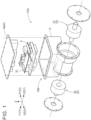
FIG. 1] FIG. 1 is a perspective view of an integrated unit. - [
FIG. 2] FIG. 2 is a partial sectional view of the integrated unit. - [
FIG. 3] FIG. 3 is a schematic diagram showing a cooling system of a first embodiment. - [
FIG. 4] FIG. 4 is a diagram showing a circuit configuration of the cooling system of the first embodiment. - [
FIG. 5] FIG. 5 is a schematic diagram showing a flow of a coolant in the cooling system of the first embodiment. - [
FIG. 6] FIG. 6 is a diagram showing the configuration of upper and lower surfaces of an oil cooler. - [
FIG. 7] FIG. 7 is a schematic diagram showing a cooling system of a second embodiment. - [
FIG. 8] FIG. 8 is a schematic diagram showing a cooling system of a third embodiment. - [
FIG. 9] FIG. 9 is a schematic diagram showing a cooling system of a fourth embodiment. - [
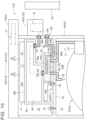
FIG. 10] FIG. 10 is a schematic diagram showing the cooling system of the fourth embodiment. - [
FIG. 11] FIG. 11 is a diagram showing a circuit configuration of the cooling system of the fourth embodiment. - [
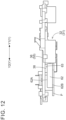
FIG. 12] FIG. 12 is a side view of a water-cooled plate housed in the integrated unit. - [
FIG. 13] FIG. 13 is a perspective view of the water-cooled plate to which the oil cooler is attached. - [
FIG. 14] FIG. 14 is a partial perspective sectional view of the integrated unit of the fourth embodiment. - [
FIG. 15] FIG. 15 is a partial side view of the integrated unit of the fourth embodiment. - [
FIG. 16] FIG. 16 is a partial side view of the integrated unit of the fourth embodiment. - [
FIG. 17] FIG. 17 is a schematic diagram showing a cooling system of a fifth embodiment. - Hereinafter, embodiments of a cooling system according to the present invention will be described with reference to the drawings. However, the present invention is not limited to the following embodiments, and various modifications may be made without departing from the spirit of the present invention.
- An electric vehicle includes an electric vehicle drive unit that drives wheels with a current supplied from a battery. Examples of the electric vehicle include vehicles including a motor as a traveling drive source (hybrid electric vehicle (HEV), plug-in hybrid electric vehicle (PHEV), battery electric vehicle (BEV), fuel cell electric vehicle (FCEV), etc.).
- The electric vehicle includes an integrated
unit 1 shown inFIGS. 1 and2 . The integratedunit 1 includes an electric vehicle drive unit 2 (hereinafter referred to as "vehicle drive unit 2"), anelectronic circuit unit 3, and acooling module 4. In the integratedunit 1, thevehicle drive unit 2 and theelectronic circuit unit 3 are integrally housed in a unit case 5 (an example of a housing). Thecooling module 4 is disposed to adjoin theelectronic circuit unit 3. In the example shown inFIG. 1 , achiller 86, a water-cooledcondenser 81, anaccumulator 82, and auxiliary devices such as valves and pumps described later and portions of a cooling channel B and a refrigerant channel D are modularized as thecooling module 4 and housed in theunit case 5. A cooling system A in the present embodiment described below is an example in which only thevehicle drive unit 2 and theelectronic circuit unit 3 are housed in theunit case 5, but the shape and structure of the integratedunit 1 are not particularly limited. In the following figures, as shown in, for example,FIG. 1 , the traveling direction of the vehicle (vehicle front-to-rear direction) may be referred to as an X direction, the width direction of the vehicle (vehicle left-to-right direction) may be referred to as a Y direction, and the height direction of the vehicle may be referred to as a Z direction. The front side in the traveling direction of the vehicle may be referred to as an X1 side, the rear side in the traveling direction may be referred to as an X2 side, the left side in the vehicle width direction may be referred to as a Y1 side, and the right side in the vehicle width direction may be referred to as a Y2 side. - The
vehicle drive unit 2 includes at least anelectric motor 21 that transmits a drive rotational force to a traveling system of the vehicle. Specifically, thevehicle drive unit 2 includes theelectric motor 21,gears 22 including a speed reducing mechanism, etc. Theelectronic circuit unit 3 includes at leastelectronic circuits 31 for driving theelectric motor 21. Specifically, theelectronic circuit unit 3 is housed in theunit case 5 to form apower supply module 100, and a plurality of electronic components constituting on-board chargers (OBCs) 32 (an example of a voltage conversion circuit) and an inverter (INV) 33 as theelectronic circuits 31 is mounted on asubstrate 35. The electronic components mounted on thesubstrate 35 are cooled by acooling plate 36 including part of asecond channel 55 of the cooling channel B described later. Thus, the electronic circuit unit 3 (power supply module 100) is coolable by a coolant flowing through the cooling channel B. - As shown in
FIGS. 3 and4 , the cooling system A includes the integratedunit 1 in which thevehicle drive unit 2 and theelectronic circuit unit 3 are integrated, the cooling channel B through which the coolant circulates to the electronic circuit unit 3 (power supply module 100), an oil channel C through which oil circulates to thevehicle drive unit 2, and the refrigerant channel D through which a refrigerant for heating and cooling a vehicle cabin circulates. A coolant such as an antifreeze liquid mainly containing ethylene glycol etc. or a long-life coolant or a coolant such as insulating oil flows through the cooling channel B. A refrigerant such as hydrofluorocarbon (HFC) flows through the refrigerant channel D. - The
electronic circuit unit 3 is disposed on an upper part of theunit case 5 and fixed to a support S. Thevehicle drive unit 2 is disposed below the support S. The disposition of thevehicle drive unit 2 and theelectronic circuit unit 3 is not limited to this. Thevehicle drive unit 2 and theelectronic circuit unit 3 may be arranged along the X direction or the Y direction. Thevehicle drive unit 2 may be disposed on the upper side and theelectronic circuit unit 3 may be disposed on the lower side. Thecooling module 4 is disposed to adjoin theelectronic circuit unit 3. Specifically, arefrigerant manifold 4a is disposed on the upper part of theunit case 5, and the water-cooledcondenser 81 is disposed on the side of therefrigerant manifold 4a. Avalve unit 6 in which awater pump 51 and a valve 52 (seeFIG. 4 ) disposed in the cooling channel B are integrated is disposed on aside surface 5A of theunit case 5 below the water-cooledcondenser 81. - The cooling channel B will be described. The cooling channel B is a channel shown above the
electric motor 21 inFIGS. 3 and4 . The cooling channel B includes thevalve unit 6, thepower supply module 100, an oil cooler 62 (an example of a heat exchanger) described later, the water-cooledcondenser 81, aradiator 53, etc. provided midway along the channel. The cooling channel B includes afirst channel 54 extending from the water-cooledcondenser 81 to theradiator 53, and thesecond channel 55 extending from theradiator 53 to the water-cooledcondenser 81. Theelectronic circuit unit 3 has part of thesecond channel 55 of the cooling channel B as an internal channel of the coolingplate 36. Part of the cooling channel B is disposed inside theunit case 5. - In the cooling channel B, the coolant circulates through the power supply module 100 (electronic circuit unit 3), the
oil cooler 62, the water-cooledcondenser 81, and theradiator 53 in this order. In the cooling channel B, the valve 52 (an example of a three-way valve) switchable between a first state in which the coolant flows through theradiator 53 and a second state in which the flow of the coolant into theradiator 53 is blocked and the coolant is diverted is disposed in thefirst channel 54 through which the coolant is supplied to theradiator 53. Thus, the cooling channel B can be switched by thevalve 52 between achannel 56 in which the coolant passes through theradiator 53 and joins thesecond channel 55 and achannel 57 in which the coolant flows without passing through theradiator 53 and joins thesecond channel 55. In the cooling channel B, thewater pump 51 is disposed downstream of thevalve 52 and theradiator 53. The cooling channel B also includes achannel 58 extending from theelectronic circuit unit 3 to theoil cooler 62, and achannel 59 extending from theoil cooler 62 to the water-cooledcondenser 81. - Next, the oil channel C will be described. The oil channel C is a channel shown below the
electronic circuit unit 3 inFIGS. 3 and4 . The oil channel C includes anoil pump 61 and the oil cooler 62 (an example of the heat exchanger) provided midway along the channel. Oil is supplied to theelectric motor 21 etc. and circulates through thevehicle drive unit 2. Theoil cooler 62 is located downstream of the power supply module 100 (electronic circuit unit 3) in the cooling channel B, and exchanges heat with the coolant circulating through the cooling channel B. - Next, the refrigerant channel D will be described. The refrigerant channel D is a channel shown on the right side in
FIG. 4 , and the refrigerant for heating and cooling circulates therethrough. The refrigerant channel D includes aheating channel 71 through which a refrigerant for heating the vehicle cabin circulates, a coolingchannel 72 through which a refrigerant for cooling the vehicle cabin circulates, and abattery cooling channel 73 through which the refrigerant circulates to cool abattery 87 mounted on the vehicle. Theheating channel 71 includes the water-cooledcondenser 81, theaccumulator 82, acompressor 83, and a cabin condenser 84 (heating condenser) disposed in this order to constitute a heat pump as a whole. The refrigerant channel D includes the water-cooledcondenser 81 provided midway along the channel to exchange heat with the coolant circulating through the cooling channel B. The water-cooledcondenser 81 is located downstream of theoil cooler 62 in the cooling channel B, and exchanges heat with the coolant circulating through the cooling channel B. - In the
heating channel 71, an on-offvalve 91 is disposed in achannel 74 between the water-cooledcondenser 81 and theaccumulator 82, and afirst expansion valve 92 is disposed in achannel 76 between thecabin condenser 84 and the water-cooledcondenser 81. In the example shown inFIG. 4 , thecompressor 83, thecabin condenser 84, and achannel 75 passing through them are disposed outside theunit case 5. - The cooling
channel 72 is constituted by achannel 77 that branches from thechannel 74 on the upstream side of the on-offvalve 91. Thechannel 77 includes asecond expansion valve 93 and anevaporator 85 provided in this order midway along the channel, and joins thechannel 74 on the downstream side of the on-offvalve 91. That is, when thesecond expansion valve 93 is driven with the on-offvalve 91 closed, the refrigerant flows through thechannel 77 and theevaporator 85 cools the vehicle cabin. In the example shown inFIG. 1 , theevaporator 85 in the coolingchannel 72 is disposed outside theunit case 5. - The
battery cooling channel 73 is constituted by achannel 78 that branches from thechannel 77 of the coolingchannel 72 on the upstream side of thesecond expansion valve 93. Thechannel 78 includes athird expansion valve 94 and thechiller 86 provided in this order midway along the channel, and joins thechannel 77 on the downstream side of theevaporator 85. That is, when thethird expansion valve 94 is driven with the on-offvalve 91 closed, the refrigerant flows through thechannel 78, and thechiller 86 exchanges heat between the refrigerant and a coolant circulating through acooling circuit 79. In the refrigerant channel D, it is preferable that the on-offvalve 91, thefirst expansion valve 92, thesecond expansion valve 93, and thethird expansion valve 94 be modularized and integrated with thecooling module 4, and be housed inside thecooling module 4. - The
battery cooling channel 73 is structured such that thechiller 86 is disposed in thecooling circuit 79 through which the coolant circulates between thechiller 86 and thebattery 87. Awater pump 88 is disposed in thecooling circuit 79 midway along the channel. In the example shown inFIG. 1 , thebattery 87 in thebattery cooling channel 73 is disposed, for example, in a space under the floor of the vehicle cabin that is located outside and rearward of theunit case 5. - In the present embodiment, the
integrated unit 1 in which thevehicle drive unit 2 and the electronic circuit unit 3 (power supply module 100) are integrated is provided. Therefore, downsizing can be achieved compared with a case where thevehicle drive unit 2 and the electronic circuit unit 3 (power supply module 100) are disposed separately. With theoil cooler 62 that exchanges heat between the coolant and the oil, waste heat of thevehicle drive unit 2 can be recovered by the coolant. - As shown in
FIGS. 2 and3 , theoil cooler 62 is disposed inside theintegrated unit 1 between thevehicle drive unit 2 and the electronic circuit unit 3 (power supply module 100). Theoil cooler 62 is disposed, for example, below theelectronic circuit unit 3 and is provided downstream of thesecond channel 55 formed inside the coolingplate 36. Thus, heat can be exchanged between the oil circulating through the oil channel C and the coolant circulating through the cooling channel B inside theintegrated unit 1, thereby improving the heat recovery rate. In the cooling channel B, the length of the pipe exposed from theoil cooler 62 to the outside can be reduced. - In this way, the cooling system A of the present embodiment can suppress dissipation of the waste heat of the
vehicle drive unit 2 from the cooling pipe, thereby achieving downsizing and efficient heat management. - The
electronic circuits 31 of theelectronic circuit unit 3 include the inverter (INV) 33 that controls the current to be supplied from thebattery 87 to theelectric motor 21, and the on-board chargers (OBCs) 32 that control the voltage for charging thebattery 87. In the present embodiment, as shown inFIG. 3 , theinverter 33 is disposed on the upper part of theelectronic circuit unit 3, and the on-board chargers 32 are disposed on the upper and lower parts of theelectronic circuit unit 3. When theelectronic circuits 31 included in theelectronic circuit unit 3 include not only theinverter 33 but also the on-board chargers 32 in this way, the cooling system A can further be downsized. The disposition of theelectronic circuits 31 mounted on theelectronic circuit unit 3 shown inFIG. 3 is an example, and the disposition of theelectronic circuits 31 may be changed as appropriate. - As shown in
FIGS. 5 ,6 , and12 , theoil cooler 62 is formed in a box shape with, for example, anupper surface 62A near theelectronic circuits 31 and alower surface 62B near theelectric motor 21. In theoil cooler 62, acoolant inlet 63 through which the coolant flows in from the top is provided on theupper surface 62A, and acoolant outlet 64 that extends toward the side of theoil cooler 62 and through which the coolant flows out is provided on thelower surface 62B. Thecoolant outlet 64 includes afirst portion 64A that is bent from thelower surface 62B toward theupper surface 62A, and asecond portion 64B that is continuous with thefirst portion 64A and extends along theupper surface 62A. The coolant can flow out from the side of theoil cooler 62 to the outside of the electronic circuit unit 3 (power supply module 100). Thechannel 59 that is continuous with the water-cooledcondenser 81 from thecoolant outlet 64 of theoil cooler 62 is formed through theside surface 5A of theunit case 5 and is disposed along the outer side of thevalve unit 6. - With this configuration, the coolant pipe connected to the
oil cooler 62 does not occupy a large area in the height direction of theoil cooler 62, and theintegrated unit 1 can be made compact even when theoil cooler 62 is disposed between thevehicle drive unit 2 and the electronic circuit unit 3 (power supply module 100). - Further, the
oil cooler 62 includes, individually on thelower surface 62B, anoil inlet 65 through which the oil flows in, and anoil outlet 66 through which the oil flows out. Thus, theintegrated unit 1 can be made compact even when theoil cooler 62 is disposed between thevehicle drive unit 2 and the electronic circuit unit 3 (power supply module 100). - The
oil outlet 66 of theoil cooler 62 is connected to asupply portion 67 that supplies the oil toward theelectric motor 21. The oil flowing out from thesupply portion 67 flows out from thelower surface 62B of theoil cooler 62 toward theelectric motor 21. In this way, the oil can flow out from thelower surface 62B of theoil cooler 62 toward theelectric motor 21. - The first embodiment illustrates the example in which the channel between the
oil cooler 62 and the water-cooledcondenser 81 is exposed to the outside. Alternatively, as shown inFIG. 7 , the valve unit 6 (cooling manifold) in which part of the cooling channel B is formed inside the housing may be attached integrally to theintegrated unit 1. Specifically, in the example shown inFIG. 7 , the water-cooledcondenser 81 and thevalve unit 6 are integrated, and thechannel 59 extending from theoil cooler 62 to the water-cooledcondenser 81 and part of thefirst channel 54 extending from the water-cooledcondenser 81 to thevalve 52 and thewater pump 51 are provided inside thevalve unit 6 to form a manifold. - In the present embodiment, the
integrated unit 1 in which thevehicle drive unit 2 and the electronic circuit unit 3 (power supply module 100) are integrated is provided. Therefore, downsizing can be achieved compared with a case where thevehicle drive unit 2 and the electronic circuit unit 3 (power supply module 100) are disposed separately. Further, theoil cooler 62 that exchanges heat between the coolant and the oil and the water-cooledcondenser 81 that exchanges heat between the coolant and the refrigerant are provided. That is, the temperature of the coolant changes in theoil cooler 62 by utilizing the waste heat of thevehicle drive unit 2 and in the water-cooledcondenser 81 by utilizing the heat of the refrigerant. - In the present embodiment, the
valve unit 6 in which part of the cooling channel B is formed inside the housing is attached integrally to theintegrated unit 1. That is, part of the cooling channel B through which the coolant circulates to exchange heat with both the oil and the refrigerant is integrated with theintegrated unit 1. Thus, the length of the cooling pipe routed in the cooling channel B can be reduced, and the dissipation of the waste heat of thevehicle drive unit 2 from the cooling pipe can be suppressed. - In this way, the cooling system A of the present embodiment can also achieve downsizing and efficient heat management.
- The
valve unit 6 in which part of the cooling channel B is formed inside the housing is disposed on the side surface of the electronic circuit unit 3 (power supply module 100). By disposing thevalve unit 6 on the side surface of theelectronic circuit unit 3, the cooling pipe of the cooling channel B extending from theoil cooler 62 disposed near thevehicle drive unit 2 adjacent to theelectronic circuit unit 3 can be designed so as not to be exposed to the outside. As a result, the dissipation of the waste heat of thevehicle drive unit 2 from the cooling pipe of the cooling channel B can be suppressed. - In the present embodiment, the water-cooled
condenser 81 is attached integrally to thevalve unit 6, and the cooling channel B that communicates with the water-cooledcondenser 81 is formed inside thevalve unit 6. Thus, the cooling pipe of the cooling channel B can be designed so as not to be exposed to the outside when heat is exchanged between the coolant circulating through the cooling channel B and the refrigerant circulating through the refrigerant channel D. As a result, the dissipation of the waste heat of thevehicle drive unit 2 from the cooling pipe of the cooling channel B can be suppressed. - In a third embodiment, as shown in
FIG. 8 , theoil cooler 62 is disposed on theside surface 5A of theunit case 5, and the water-cooledcondenser 81, thevalve unit 6, and theoil cooler 62 are attached integrally to theintegrated unit 1. The channels of the cooling channel B that communicate with the water-cooledcondenser 81 and theoil cooler 62 are formed Inside thevalve unit 6. Specifically, thechannel 58 extending from the electronic circuit unit 3 (power supply module 100) to theoil cooler 62, thechannel 59 extending from theoil cooler 62 to the water-cooledcondenser 81, and part of thefirst channel 54 extending from the water-cooledcondenser 81 to thevalve 52 and thewater pump 51 are provided inside thevalve unit 6 to form a manifold. - By integrally attaching, to the
valve unit 6, theoil cooler 62 disposed in the oil channel C through which the oil is supplied to thevehicle drive unit 2 as in the present embodiment, the cooling pipe of the cooling channel B can be designed so as not to be exposed to the outside when heat is exchanged between the coolant and the oil. As a result, the dissipation of the waste heat of thevehicle drive unit 2 from the cooling pipe of the cooling channel B can be suppressed. - In a fourth embodiment, as shown in
FIG. 9 , theintegrated unit 1 has afirst space 11 in which thevehicle drive unit 2 is disposed, asecond space 12 in which theelectronic circuit unit 3 is disposed, and a partition wall S1 that separates thefirst space 11 and thesecond space 12. That is, theintegrated unit 1 is partitioned into thefirst space 11 at the bottom and thesecond space 12 at the top by the partition wall S1. - The
electronic circuit unit 3 is disposed on the upper part of theunit case 5 and fixed to the partition wall S1. Thevehicle drive unit 2 is disposed below the partition wall S1. As shown inFIG. 9 , thecooling module 4 is disposed to adjoin theelectronic circuit unit 3. Specifically, therefrigerant manifold 4a is disposed on the upper part of theunit case 5, and the water-cooledcondenser 81 is attached to theside surface 5A (an example of an outer surface) of theunit case 5. In this way, theintegrated unit 1 includes thecooling module 4 in which therefrigerant manifold 4a including the refrigerant channel D through which the refrigerant flows and the water-cooledcondenser 81 are integrated. In thecooling module 4, therefrigerant manifold 4a is located above the water-cooledcondenser 81. - As shown in
FIG. 10 , thevalve unit 6 is disposed on theside surface 5A of theunit case 5. In the present embodiment, on theside surface 5A of theunit case 5, the water-cooledcondenser 81 is located on the left side (Y1 direction side) of the front side (X1 direction side), and thevalve unit 6 is located on the right side (Y2 direction side) of the front side (X1 direction side). - As shown in
FIGS. 9 and10 , thesecond space 12 of theunit case 5 houses theelectronic circuit unit 3 and the coolingplate 36 for cooling thepower supply module 100. The coolingplate 36 is made of a metal having high thermal conductivity, such as aluminum, and is integrally formed by joining alower plate 36a and anupper plate 36b each having a plate shape by a method such as welding. The coolingplate 36 has a space inside (between thelower plate 36a and theupper plate 36b), and the coolant flows through the space. By exchanging heat between thepower supply module 100 and the coolant, the temperature of thepower supply module 100 is reduced and the temperature of the coolant is increased. - As shown in
FIGS. 9 and10 , thesecond channel 55 of the coolingplate 36 is disposed in a horizontal direction. In the present embodiment, the coolant flows in through aninlet 37 of the coolingplate 36 and flows out through anoutlet 38. - The
oil cooler 62 is engaged with the coolingplate 36 via a projection and a recess while being disposed in thesecond space 12. Specifically, theoutlet 38 formed in thelower plate 36a of the coolingplate 36 is a tubular portion that protrudes downward, and theoutlet 38 of the coolingplate 36 is inserted and fitted into thecoolant inlet 63 of theoil cooler 62. Although illustration is omitted, thecoolant inlet 63 of theoil cooler 62 may be formed as a tubular portion that protrudes upward, and theoutlet 38 of the coolingplate 36 may be formed as an opening. In this case, the coolant inlet 63 (tubular portion) of theoil cooler 62 is inserted and fitted into theoutlet 38 of the coolingplate 36. A support plate P is joined to thelower surface 62B of theoil cooler 62, and theoil cooler 62 is positioned relative to the partition wall S1 and fastened to the partition wall S1 withscrew members 40 etc. (seeFIG. 10 as well). Similarly, theelectronic circuit unit 3 including thecooling plate 36 is positioned relative to the partition wall S1 and fastened to the partition wall S1 withscrew members 41 etc. (seeFIG. 10 as well). - As shown in
FIG. 13 , in the present embodiment, the combination of thecoolant inlet 63 and thecoolant outlet 64 and the combination of theoil inlet 65 and theoil outlet 66 in theoil cooler 62 are each disposed diagonally on a plane projected along thelower plate 36a of the coolingplate 36. Specifically, on the plane projected along thelower plate 36a of the coolingplate 36, thecoolant inlet 63 is disposed on the X1 direction side and the Y1 direction side, and thecoolant outlet 64 is disposed on the X2 direction side and the Y2 direction side. Similarly, on the plane projected along thelower plate 36a, theoil inlet 65 is disposed on the X2 direction side and the Y1 direction side, and theoil outlet 66 is disposed on the X1 direction side and the Y2 direction side. - As shown in
FIG. 14 , theoil cooler 62 and the water-cooledcondenser 81 are disposed at positions where they face each other across the wall (side surface 5A) of theunit case 5. As shown inFIG. 9 , the water-cooledcondenser 81 is attached to theside surface 5A of theunit case 5 at a position near theoil cooler 62. Achannel portion 68 is provided between thecoolant outlet 64 and the water-cooledcondenser 81. In the example shown inFIG. 9 , thechannel portion 68 includes afirst portion 68a formed along the wall surface of the partition wall S1, asecond portion 68b bent from thelower surface 62B toward theupper surface 62A, and athird portion 68c extending in the same direction as that of thefirst portion 68a and continuous with the inside and outside of theunit case 5. That is, thethird portion 68c is formed through theside surface 5A of theunit case 5 and is connected to the inside of the water-cooledcondenser 81. - As shown in
FIG. 14 , thechannel portion 68 may include only thefirst portion 68a along the partition wall S1 between thecoolant outlet 64 of theoil cooler 62 and the water-cooledcondenser 81 without thesecond portion 68b and thethird portion 68c. - By disposing the
oil cooler 62 and the water-cooledcondenser 81 close to each other and providing thechannel portion 68 between thecoolant outlet 64 and the water-cooledcondenser 81 in this way, the coolant pipe portion (channel portion 68) connected to theoil cooler 62 does not occupy a large area in the height direction of theoil cooler 62, and theintegrated unit 1 can be made compact even when theoil cooler 62 is disposed between thevehicle drive unit 2 and the electronic circuit unit 3 (power supply module 100). - As shown in
FIGS. 10 ,15 , and16 , thewater pump 51 is fixed to theside surface 5A of theunit case 5 at a position where it overlaps at least part of the coolingplate 36 in side view. As shown inFIG. 10 , thewater pump 51 is disposed on the same side as that of theradiator 53 with respect to theintegrated unit 1. - As shown in
FIGS. 15 and16 , thewater pump 51 includes acoolant suction port 51a and acoolant discharge port 51b, and is disposed so that thecoolant discharge port 51b overlaps at least part of the coolingplate 36 in side view. Specifically, thecoolant discharge port 51b of thewater pump 51 is positioned within a width W of the coolingplate 36 in the vertical direction. - As shown in the schematic diagram of
FIG. 10 , thecoolant discharge port 51b of thewater pump 51 and theinlet 37 of the coolingplate 36 are connected by aconnection channel 39. Theconnection channel 39 is provided below the coolingplate 36 and is formed along the bottom surface (lower plate 36a) of the coolingplate 36. - The fourth embodiment illustrates the example in which the
refrigerant manifold 4a and the water-cooledcondenser 81 are integrated and disposed outside theunit case 5. Alternatively, as shown inFIG. 17 , therefrigerant manifold 4a and the water-cooledcondenser 81 may be separated, and therefrigerant manifold 4a and the water-cooledcondenser 81 may be attached individually to theintegrated unit 1. Specifically, as shown inFIG. 17 , theintegrated unit 1 includes therefrigerant manifold 4a including the refrigerant channel D through which the refrigerant flows in a state in which therefrigerant manifold 4a is disposed above and separately from the water-cooledcondenser 81, and the water-cooledcondenser 81 is connected to theunit case 5 from the lateral side. - By connecting the water-cooled
condenser 81 to theunit case 5 from the lateral side as in the present embodiment, the length of the pipe between theoil cooler 62 and the water-cooledcondenser 81 can be reduced, and theintegrated unit 1 can be made compact. -
- (1) The above embodiments illustrate the example in which the
water pump 51 and thevalve 52 are integrated in the cooling channel B. However, thewater pump 51 and thevalve 52 may be provided separately, or thewater pump 51 and thevalve 52 may be housed in individual housings. - (2) The flow directions of the coolant and the refrigerant or the flow directions of the coolant and the oil for heat exchange may be the same directions or opposite directions.
- (3) In the
integrated unit 1 in the above embodiments, thevehicle drive unit 2 and theelectronic circuit unit 3 are integrally housed in theunit case 5. However, thevehicle drive unit 2 and theelectronic circuit unit 3 may be housed in different cases and the cases may be connected together. - (4) The above embodiments illustrate the example in which the
oil cooler 62 includes thecoolant inlet 63 provided on theupper surface 62A and thecoolant outlet 64 provided on thelower surface 62B. Alternatively, theoil cooler 62 may include both thecoolant inlet 63 and thecoolant outlet 64 provided on theupper surface 62A. - Hereinafter, the summary of the cooling system A described above will be provided.
- (1) The characteristic configuration of the cooling system A is as follows. The cooling system A includes: the
integrated unit 1 in which the electricvehicle drive unit 2 including at least theelectric motor 21 configured to transmit the drive rotational force to the traveling system of the vehicle and theelectronic circuit unit 3 including at least theelectronic circuit 31 configured to drive theelectric motor 21 are integrated; the cooling channel B through which the coolant circulates to theelectronic circuit unit 3; and the oil channel C that includes the heat exchanger (oil cooler 62) configured to exchange heat with the coolant circulating through the cooling channel B and through which the oil circulates to the electricvehicle drive unit 2. The heat exchanger (oil cooler 62) is disposed inside theintegrated unit 1 between the electricvehicle drive unit 2 and theelectronic circuit unit 3. - In this configuration, the
integrated unit 1 in which the electricvehicle drive unit 2 and theelectronic circuit unit 3 are integrated is provided. Therefore, theintegrated unit 1 can be downsized compared with a case where the electricvehicle drive unit 2 and theelectronic circuit unit 3 are disposed separately. With the heat exchanger (oil cooler 62) that exchanges heat between the coolant and the oil, the waste heat of the electricvehicle drive unit 2 and the waste heat of theelectronic circuit unit 3 can be recovered by the coolant. - In this configuration, the heat exchanger (oil cooler 62) is disposed inside the
integrated unit 1 between the electricvehicle drive unit 2 and theelectronic circuit unit 3. Thus, heat can be exchanged between the oil and the coolant inside theintegrated unit 1, thereby improving the heat recovery rate. In the cooling channel B, the length of the pipe exposed from the heat exchanger (oil cooler 62) to the outside can be reduced. - In this way, the cooling system can suppress the dissipation of the waste heat of the electric vehicle drive unit from the cooling pipe, thereby achieving downsizing and efficient heat management.
- (2) In the cooling system A according to (1), it is preferable that the cooling system A further include the cooling
plate 36 to which theelectronic circuit unit 3 is fixed and through which the coolant flows, and the heat exchanger (oil cooler 62) be disposed between the electricvehicle drive unit 2 and the coolingplate 36. - In this configuration, the
electronic circuit unit 3 is fixed to thecooling plate 36. Thus, the heat generated by theelectronic circuit unit 3 can be recovered by the coolant, and the heat recovery rate can be improved. In this configuration, the heat exchanger (oil cooler 62) is disposed inside theintegrated unit 1 between the electricvehicle drive unit 2 and the coolingplate 36. Thus, heat can be exchanged between the oil and the coolant inside theintegrated unit 1, thereby improving the heat recovery rate. In the cooling channel B, the length of the pipe exposed from the heat exchanger (oil cooler 62) to the outside can be reduced. - (3) In the cooling system A according to (2), it is preferable that the heat exchanger (oil cooler 62) be disposed below the cooling
plate 36. - With this configuration, the coolant can smoothly flow from the cooling
plate 36 to the heat exchanger (oil cooler 62), and the length of the pipe disposed between the coolingplate 36 and the heat exchanger (oil cooler 62) can be reduced. - (4) In the cooling system A according to any one of (1) to (3), it is preferable that the
integrated unit 1 include the electricvehicle drive unit 2 and theelectronic circuit unit 3 built into the housing (unit case 5). - Since the electric
vehicle drive unit 2 and theelectronic circuit unit 3 are integrally built into the housing (unit case 5), theintegrated unit 1 can be downsized. - (5) In the cooling system A according to any one of (1) to (3), it is preferable that the
electronic circuit 31 include theinverter 33 configured to control the current to be supplied from thebattery 87 to theelectric motor 21, and the voltage conversion circuit configured to control the voltage for charging thebattery 87. - When the
electronic circuit 31 included in theelectronic circuit unit 3 includes not only theinverter 33 but also the voltage conversion circuit as in this configuration, further downsizing can be achieved. - (6) In the cooling system A according to any one of (1) to (5), it is preferable that the heat exchanger (oil cooler 62) include, individually on the
lower surface 62B near theelectric motor 21, theoil inlet 65 through which the oil flows in and theoil outlet 66 through which the oil flows out. - When the heat exchanger (oil cooler 62) is structured such that the oil flows in and out from the
lower surface 62B as in this configuration, theintegrated unit 1 can be made compact even when the heat exchanger (oil cooler 62) is disposed between the electricvehicle drive unit 2 and theelectronic circuit unit 3. - (7) In the cooling system A according to any one of (2) to (5), it is preferable that the heat exchanger (oil cooler 62) include, on the
upper surface 62A near the coolingplate 36, thecoolant inlet 63 through which the coolant flows in and include, individually on thelower surface 62B near theelectric motor 21, thecoolant outlet 64 through which the coolant flows out, theoil inlet 65, and theoil outlet 66. - When the heat exchanger (oil cooler 62) is structured such that the oil flows in and out from the
lower surface 62B and the heat exchanger (oil cooler 62) includes thecoolant inlet 63 on theupper surface 62A and thecoolant outlet 64 on thelower surface 62B as in this configuration, theintegrated unit 1 can be made compact even when the heat exchanger (oil cooler 62) is disposed between the electricvehicle drive unit 2 and theelectronic circuit unit 3. - (8) In the cooling system A according to (6) or (7), it is preferable that the oil flow out from the
lower surface 62B toward theelectric motor 21. - Since the oil flows out from the
lower surface 62B of the heat exchanger (oil cooler 62) toward theelectric motor 21 as in this configuration, theelectric motor 21 can be cooled effectively. - (9) In the cooling system A according to (2) or (3), it is preferable that the heat exchanger (oil cooler 62) include the
coolant outlet 64 that extends from thelower surface 62B near theelectric motor 21 and through which the coolant flows out, and the cooling channel B extending from thecoolant outlet 64 to the outside of theelectronic circuit unit 3 be disposed below theupper surface 62A of the heat exchanger (oil cooler 62) near the coolingplate 36. - When the cooling channel B extending from the
coolant outlet 64 of the heat exchanger (oil cooler 62) to the outside of theelectronic circuit unit 3 is disposed below theupper surface 62A of the heat exchanger (oil cooler 62) near the coolingplate 36 as in this configuration, the cooling pipe does not occupy the heat exchanger (oil cooler 62) in the height direction, and theintegrated unit 1 can be made compact even when the heat exchanger (oil cooler 62) is disposed between the electricvehicle drive unit 2 and the coolingplate 36. - (10) In the cooling system A according to (9), it is preferable that the
coolant outlet 64 include thefirst portion 68a that is bent from thelower surface 62B toward theupper surface 62A, and thesecond portion 68b that is continuous with thefirst portion 68a and extends along theupper surface 62A, and the coolant be flowable out from the side of the heat exchanger (oil cooler 62) to the outside of theelectronic circuit unit 3. - When the
coolant outlet 64 of the heat exchanger (oil cooler 62) includes thefirst portion 68a that is bent from thelower surface 62B toward theupper surface 62A, and thesecond portion 68b that is continuous with thefirst portion 68a and extends along theupper surface 62A, and the coolant is flowable out from the side of the heat exchanger (oil cooler 62) to the outside of theelectronic circuit unit 3 as in this configuration, the cooling pipe does not occupy the heat exchanger (oil cooler 62) in the height direction, and theintegrated unit 1 can be made compact even when the heat exchanger (oil cooler 62) is disposed between the electricvehicle drive unit 2 and the coolingplate 36. - (11) In the cooling system A according to (2) or (3), it is preferable that the heat exchanger (oil cooler 62) be engaged with the cooling
plate 36 via a projection and a recess. - With this configuration, heat can be exchanged between the oil and the cooling fluid inside the
integrated unit 1, thereby improving the heat recovery rate. In the channel through which the cooling fluid flows, the length of the pipe between the heat exchanger (oil cooler 62) and the coolingplate 36 can be reduced. Thus, the cooling system A can suppress the dissipation of the waste heat of the electricvehicle drive unit 2 from the cooling pipe, thereby achieving downsizing and efficient heat management. - (12) In the cooling system A according to (11), it is preferable that the cooling
plate 36 include thetubular outlet 38 that protrudes toward the heat exchanger (oil cooler 62), the heat exchanger (oil cooler 62) include, on theupper surface 62A near the coolingplate 36, thecoolant inlet 63 through which the coolant flows in, and theoutlet 38 be fitted into thecoolant inlet 63. - In this configuration, the
tubular outlet 38 of the coolingplate 36 and thecoolant inlet 63 of the heat exchanger (oil cooler 62) are fitted together. Therefore, there is no need to install a pipe between the coolingplate 36 and the heat exchanger (oil cooler 62). Thus, the number of components can be reduced and theintegrated unit 1 can be downsized. - (13) In the cooling system A according to (11), it is preferable that the heat exchanger (oil cooler 62) include the
tubular coolant inlet 63 that protrudes from the upper surface 62Anear the coolingplate 36 and through which the coolant flows in, and thecoolant inlet 63 be fitted into theoutlet 38 of the coolingplate 36. - In this configuration, the
outlet 38 of the coolingplate 36 and thetubular coolant inlet 63 of the heat exchanger (oil cooler 62) are fitted together. Therefore, there is no need to install a pipe between the coolingplate 36 and the heat exchanger (oil cooler 62). Thus, the number of components can be reduced and theintegrated unit 1 can be downsized. - (14) In the cooling system A according to any one of (1) to (3), it is preferable that the
integrated unit 1 include the partition wall S1 that separates thefirst space 11 in which the electricvehicle drive unit 2 is disposed and thesecond space 12 in which theelectronic circuit unit 3 is disposed, and the heat exchanger (oil cooler 62) be disposed in thesecond space 12. - In this configuration, the
integrated unit 1 includes the partition wall S1 that separates thefirst space 11 in which the electricvehicle drive unit 2 is disposed and thesecond space 12 in which theelectronic circuit unit 3 is disposed. Therefore, the electricvehicle drive unit 2 and theelectronic circuit unit 3 can easily be disposed at predetermined positions in theintegrated unit 1. Since the heat exchanger (oil cooler 62) is disposed in thesecond space 12, the heat exchanger (oil cooler 62) and the coolingplate 36 can easily be engaged with each other. - (15) In the cooling system A according to (14), it is preferable that the heat exchanger (oil cooler 62) be fastened to the partition wall S1.
- By fastening the heat exchanger (oil cooler 62) to the partition wall S1 as in this configuration, the
integrated unit 1 can further be downsized. By fastening the heat exchanger (oil cooler 62) to the partition wall S1, the heat exchanger (oil cooler 62) can be attached from the top of theintegrated unit 1. - (16) In the cooling system A according to (15), it is preferable that the
integrated unit 1 include the support plate P that supports the heat exchanger (oil cooler 62), and the heat exchanger (oil cooler 62) be positioned relative to the partition wall S1 by the support plate P. - When the support plate P determines the position of the heat exchanger (oil cooler 62) relative to the partition wall S1 as in this configuration, the heat exchanger (oil cooler 62) can be installed with high accuracy relative to the partition wall S1. Therefore, the heat exchanger (oil cooler 62) can be installed at a position where the length of the pipe can be reduced. Thus, the
integrated unit 1 can be downsized. - The following configurations are also possible from the above embodiments.
- (17) The characteristic configuration of the cooling system A is as follows. The cooling system A includes: the
integrated unit 1 in which the electricvehicle drive unit 2 including at least theelectric motor 21 configured to transmit the drive rotational force to the traveling system of the vehicle and theelectronic circuit unit 3 including at least theelectronic circuit 31 configured to drive theelectric motor 21 are integrated; the cooling channel B through which the coolant circulates to theelectronic circuit unit 3; the oil channel C that includes the heat exchanger (oil cooler 62) configured to exchange heat with the coolant circulating through the cooling channel B and through which the oil circulates to the electricvehicle drive unit 2; and the refrigerant channel D that includes the water-cooledcondenser 81 configured to exchange heat with the coolant circulating through the cooling channel B and through which the refrigerant for heating and cooling circulates. The cooling manifold (valve unit 6) in which part of the cooling channel B is formed inside the housing is attached integrally to theintegrated unit 1. - In this configuration, the
integrated unit 1 in which the electricvehicle drive unit 2 and theelectronic circuit unit 3 are integrated is provided. Therefore, downsizing can be achieved compared with a case where the electricvehicle drive unit 2 and theelectronic circuit unit 3 are disposed separately. Further, the heat exchanger (oil cooler 62) that exchanges heat between the coolant and the oil and the water-cooledcondenser 81 that exchanges heat between the coolant and the refrigerant are provided. That is, the temperature of the coolant changes in the heat exchanger (oil cooler 62) by utilizing the waste heat of the electricvehicle drive unit 2 and in the water-cooledcondenser 81 by utilizing the heat of the refrigerant. - In this configuration, the cooling manifold (valve unit 6) in which part of the cooling channel B is formed inside the housing is attached integrally to the
integrated unit 1. That is, part of the cooling channel B through which the coolant circulates to exchange heat with both the oil and the refrigerant is integrated with theintegrated unit 1. Thus, the length of the cooling pipe routed in the cooling channel B can be reduced, and the dissipation of the waste heat of the electricvehicle drive unit 2 from the cooling pipe can be suppressed. - In this way, the cooling system A can achieve downsizing and efficient heat management.
- (18) In the cooling system A according to (17), it is preferable that the cooling manifold (valve unit 6) be disposed on the side surface of the
electronic circuit unit 3. - By disposing the cooling manifold (valve unit 6) on the side surface of the
electronic circuit unit 3 as in this configuration, the cooling pipe of the cooling channel B extending from the heat exchanger (oil cooler 62) provided to the electricvehicle drive unit 2 adjacent to theelectronic circuit unit 3 can be designed so as not to be exposed to the outside. As a result, the dissipation of the waste heat of the electricvehicle drive unit 2 from the cooling pipe of the cooling channel B can be suppressed. - (19) In the cooling system A according to (17) or (18), it is preferable that the water-cooled
condenser 81 be attached integrally to the cooling manifold (valve unit 6). - By integrally attaching the water-cooled
condenser 81 to the cooling manifold (valve unit 6) as in this configuration, the cooling pipe can be designed so as not to be exposed to the outside when heat is exchanged between the coolant and the refrigerant. As a result, the dissipation of the waste heat of the electricvehicle drive unit 2 from the cooling pipe can be suppressed. - (20) In the cooling system A according to any one of (17) to (19), it is preferable that the heat exchanger (oil cooler 62) be attached integrally to the cooling manifold (valve unit 6).
- By integrally attaching, to the cooling manifold (valve unit 6), the heat exchanger (oil cooler 62) provided to the electric
vehicle drive unit 2 as in this configuration, the cooling pipe can be designed so as not to be exposed to the outside when heat is exchanged between the coolant and the oil. As a result, the dissipation of the waste heat of the electricvehicle drive unit 2 from the cooling pipe can be suppressed. - (21) In the cooling system A according to any one of (17) to (20), it is preferable that the heat exchanger (oil cooler 62) be disposed inside the
integrated unit 1 between the electricvehicle drive unit 2 and theelectronic circuit unit 3. - When the heat exchanger (oil cooler 62) is disposed inside the
integrated unit 1 between the electricvehicle drive unit 2 and theelectronic circuit unit 3 as in this configuration, heat can be exchanged between the oil and the coolant inside theintegrated unit 1, thereby improving the heat recovery rate. - The present invention is widely applicable to cooling systems for electric vehicles.
- 1: integrated unit, 2: electric vehicle drive unit, 3: electronic circuit unit, 5: unit case (housing), 11: first space, 12: second space, 21: electric motor, 31: electronic circuit, 32: on-board charger (voltage conversion circuit), 33: inverter, 36: cooling plate, 37: inlet, 38: outlet, 53: radiator, 62: oil cooler (heat exchanger), 62A: upper surface, 62B: lower surface, 63: coolant inlet, 64: coolant outlet, 64A: first portion, 64B: second portion, 65: oil inlet, 66: oil outlet, A: cooling system, B: cooling channel, C: oil channel, D: refrigerant channel, S1: partition wall, P: support plate
Claims (16)
- A cooling system comprising:an integrated unit in which an electric vehicle drive unit including at least an electric motor configured to transmit a drive rotational force to a traveling system of a vehicle and an electronic circuit unit including at least an electronic circuit configured to drive the electric motor are integrated;a cooling channel through which a coolant circulates to the electronic circuit unit; andan oil channel that includes a heat exchanger configured to exchange heat with the coolant circulating through the cooling channel and through which oil circulates to the electric vehicle drive unit, wherein the heat exchanger is disposed inside the integrated unit between the electric vehicle drive unit and the electronic circuit unit.
- The cooling system according to claim 1, further comprising a cooling plate to which the electronic circuit unit is fixed and through which the coolant flows, wherein the heat exchanger is disposed between the electric vehicle drive unit and the cooling plate.
- The cooling system according to claim 2, wherein the heat exchanger is disposed below the cooling plate.
- The cooling system according to any one of claims 1 to 3, wherein the integrated unit includes the electric vehicle drive unit and the electronic circuit unit built into a housing.
- The cooling system according to any one of claims 1 to 3, wherein the electronic circuit includes an inverter configured to control a current to be supplied from a battery to the electric motor, and a voltage conversion circuit configured to control a voltage for charging the battery.
- The cooling system according to any one of claims 1 to 3, wherein the heat exchanger includes, individually on a lower surface near the electric motor, an oil inlet through which the oil flows in and an oil outlet through which the oil flows out.
- The cooling system according to claim 2 or 3, whereinthe heat exchanger includes, on an upper surface near the cooling plate, a coolant inlet through which the coolant flows in, andthe heat exchanger includes, individually on a lower surface near the electric motor, a coolant outlet through which the coolant flows out, an oil inlet through which the oil flows in, and an oil outlet through which the oil flows out.
- The cooling system according to claim 6, wherein the oil flows out from the lower surface toward the electric motor.
- The cooling system according to claim 2 or 3, whereinthe heat exchanger includes a coolant outlet that extends from a lower surface near the electric motor and through which the coolant flows out, andthe cooling channel extending from the coolant outlet to an outside of the electronic circuit unit is disposed below an upper surface of the heat exchanger near the cooling plate.
- The cooling system according to claim 9, wherein the coolant outlet includes a first portion that is bent from the lower surface toward the upper surface, and a second portion that is continuous with the first portion and extends along the upper surface, and the coolant is flowable out from a side of the heat exchanger to the outside of the electronic circuit unit.
- The cooling system according to claim 2 or 3, wherein the heat exchanger is engaged with the cooling plate via a projection and a recess.
- The cooling system according to claim 11, whereinthe cooling plate includes a tubular outlet that protrudes toward the heat exchanger,the heat exchanger includes, on an upper surface near the cooling plate, a coolant inlet through which the coolant flows in, andthe outlet is fitted into the coolant inlet.
- The cooling system according to claim 11, whereinthe heat exchanger includes a tubular coolant inlet that protrudes from an upper surface near the cooling plate and through which the coolant flows in, andthe coolant inlet is fitted into an outlet of the cooling plate.
- The cooling system according to any one of claims 1 to 3, whereinthe integrated unit includes a partition wall that separates a first space in which the electric vehicle drive unit is disposed and a second space in which the electronic circuit unit is disposed, andthe heat exchanger is disposed in the second space.
- The cooling system according to claim 14, wherein the heat exchanger is fastened to the partition wall.
- The cooling system according to claim 15, whereinthe integrated unit includes a support plate that supports the heat exchanger, andthe heat exchanger is positioned relative to the partition wall by the support plate.
Applications Claiming Priority (4)
| Application Number | Priority Date | Filing Date | Title |
|---|---|---|---|
| JP2022183674 | 2022-11-16 | ||
| JP2022183675 | 2022-11-16 | ||
| JP2023089637 | 2023-05-31 | ||
| PCT/JP2023/040548 WO2024106330A1 (en) | 2022-11-16 | 2023-11-10 | Cooling system |
Publications (2)
| Publication Number | Publication Date |
|---|---|
| EP4576519A1 true EP4576519A1 (en) | 2025-06-25 |
| EP4576519A4 EP4576519A4 (en) | 2025-12-17 |
Family
ID=91084494
Family Applications (1)
| Application Number | Title | Priority Date | Filing Date |
|---|---|---|---|
| EP23891479.0A Pending EP4576519A4 (en) | 2022-11-16 | 2023-11-10 | COOLING SYSTEM |
Country Status (4)
| Country | Link |
|---|---|
| EP (1) | EP4576519A4 (en) |
| JP (1) | JPWO2024106330A1 (en) |
| CN (1) | CN120130016A (en) |
| WO (1) | WO2024106330A1 (en) |
Family Cites Families (5)
| Publication number | Priority date | Publication date | Assignee | Title |
|---|---|---|---|---|
| JP3886697B2 (en) * | 1999-04-27 | 2007-02-28 | アイシン・エィ・ダブリュ株式会社 | Drive device |
| JP3794392B2 (en) * | 2003-02-25 | 2006-07-05 | 日産自動車株式会社 | Electric vehicle drive unit |
| JP7310259B2 (en) | 2019-04-19 | 2023-07-19 | ニデック株式会社 | motor unit |
| JP2021069255A (en) * | 2019-10-28 | 2021-04-30 | トヨタ自動車株式会社 | Driving device |
| JP7456189B2 (en) * | 2020-02-28 | 2024-03-27 | ニデック株式会社 | drive device |
-
2023
- 2023-11-10 WO PCT/JP2023/040548 patent/WO2024106330A1/en not_active Ceased
- 2023-11-10 CN CN202380074227.8A patent/CN120130016A/en active Pending
- 2023-11-10 EP EP23891479.0A patent/EP4576519A4/en active Pending
- 2023-11-10 JP JP2024558828A patent/JPWO2024106330A1/ja active Pending
Also Published As
| Publication number | Publication date |
|---|---|
| EP4576519A4 (en) | 2025-12-17 |
| CN120130016A (en) | 2025-06-10 |
| WO2024106330A1 (en) | 2024-05-23 |
| JPWO2024106330A1 (en) | 2024-05-23 |
Similar Documents
| Publication | Publication Date | Title |
|---|---|---|
| KR102942522B1 (en) | Integrated electric drive system and electric vehicle | |
| EP3786758A1 (en) | Vehicle-mounted computing device in smart automobile, and smart automobile | |
| US7051787B2 (en) | Cooling apparatus of a vehicle | |
| CN110718724A (en) | Cooling units, battery temperature control systems, and vehicles | |
| JP2024172115A (en) | Vehicle Drive Unit | |
| JP2024172114A (en) | Vehicle Drive Unit | |
| US12366196B2 (en) | Component housing unit and a vehicle thermal management system comprising a component housing unit | |
| US20140287284A1 (en) | Cooling system for vehicular battery | |
| JP7507538B2 (en) | Vehicle and battery pack | |
| US12392275B2 (en) | Water supply module integrated with reservoir tank | |
| US20230100546A1 (en) | Cooling system for an electric vehicle | |
| CN107195985A (en) | The battery-mounting method of vehicle, battery unit and vehicle | |
| EP4576519A1 (en) | Cooling system | |
| CN113678303A (en) | Cooling device and housing | |
| EP4667253A1 (en) | Vehicle drive device | |
| JP4483792B2 (en) | Cooling system | |
| JP7207342B2 (en) | vehicle battery pack | |
| CN212796519U (en) | Front structure of vehicle | |
| CN119301001A (en) | Cooler assembly arrangement for a motor vehicle having a plurality of heat exchangers and motor vehicle having a cooler assembly arrangement | |
| KR102948590B1 (en) | Cooling module for vehicle | |
| US20250246994A1 (en) | Power conversion device | |
| JP7622677B2 (en) | Oil cooler | |
| CN119636458B (en) | On-board chargers, powertrains, and electric vehicles with a three-dimensional water-cooling circuit | |
| EP4691820A1 (en) | Mounting structure for heat exchanger | |
| CN220923785U (en) | All-terrain vehicle |
Legal Events
| Date | Code | Title | Description |
|---|---|---|---|
| STAA | Information on the status of an ep patent application or granted ep patent |
Free format text: STATUS: THE INTERNATIONAL PUBLICATION HAS BEEN MADE |
|
| PUAI | Public reference made under article 153(3) epc to a published international application that has entered the european phase |
Free format text: ORIGINAL CODE: 0009012 |
|
| STAA | Information on the status of an ep patent application or granted ep patent |
Free format text: STATUS: REQUEST FOR EXAMINATION WAS MADE |
|
| 17P | Request for examination filed |
Effective date: 20250320 |
|
| AK | Designated contracting states |
Kind code of ref document: A1 Designated state(s): AL AT BE BG CH CY CZ DE DK EE ES FI FR GB GR HR HU IE IS IT LI LT LU LV MC ME MK MT NL NO PL PT RO RS SE SI SK SM TR |
|
| A4 | Supplementary search report drawn up and despatched |
Effective date: 20251118 |
|
| RIC1 | Information provided on ipc code assigned before grant |
Ipc: H02K 9/19 20060101AFI20251112BHEP Ipc: B60H 1/22 20060101ALI20251112BHEP Ipc: B60K 1/00 20060101ALI20251112BHEP Ipc: B60K 1/04 20190101ALI20251112BHEP Ipc: B60K 11/02 20060101ALI20251112BHEP Ipc: B60K 11/04 20060101ALI20251112BHEP Ipc: B60L 1/00 20060101ALI20251112BHEP Ipc: B60L 15/00 20060101ALI20251112BHEP Ipc: F01P 3/20 20060101ALI20251112BHEP Ipc: F01P 3/22 20060101ALI20251112BHEP Ipc: F01P 7/14 20060101ALI20251112BHEP Ipc: F01P 11/04 20060101ALI20251112BHEP Ipc: F01P 11/08 20060101ALI20251112BHEP Ipc: F25B 1/00 20060101ALI20251112BHEP Ipc: H02K 11/33 20160101ALI20251112BHEP Ipc: H05K 7/20 20060101ALI20251112BHEP Ipc: B60H 1/00 20060101ALI20251112BHEP Ipc: B60L 1/02 20060101ALI20251112BHEP Ipc: F01P 3/00 20060101ALI20251112BHEP Ipc: F25B 5/02 20060101ALI20251112BHEP Ipc: F25B 6/04 20060101ALI20251112BHEP |
|
| DAV | Request for validation of the european patent (deleted) | ||
| DAX | Request for extension of the european patent (deleted) |