EP4576514A1 - Electric drive apparatus - Google Patents
Electric drive apparatus Download PDFInfo
- Publication number
- EP4576514A1 EP4576514A1 EP22955674.1A EP22955674A EP4576514A1 EP 4576514 A1 EP4576514 A1 EP 4576514A1 EP 22955674 A EP22955674 A EP 22955674A EP 4576514 A1 EP4576514 A1 EP 4576514A1
- Authority
- EP
- European Patent Office
- Prior art keywords
- orthogonal direction
- rotation shaft
- reduction gear
- inverter
- opening part
- Prior art date
- Legal status (The legal status is an assumption and is not a legal conclusion. Google has not performed a legal analysis and makes no representation as to the accuracy of the status listed.)
- Pending
Links
Images




Classifications
-
- H—ELECTRICITY
- H02—GENERATION; CONVERSION OR DISTRIBUTION OF ELECTRIC POWER
- H02K—DYNAMO-ELECTRIC MACHINES
- H02K7/00—Arrangements for handling mechanical energy structurally associated with dynamo-electric machines, e.g. structural association with mechanical driving motors or auxiliary dynamo-electric machines
- H02K7/10—Structural association with clutches, brakes, gears, pulleys or mechanical starters
- H02K7/116—Structural association with clutches, brakes, gears, pulleys or mechanical starters with gears
-
- B—PERFORMING OPERATIONS; TRANSPORTING
- B60—VEHICLES IN GENERAL
- B60K—ARRANGEMENT OR MOUNTING OF PROPULSION UNITS OR OF TRANSMISSIONS IN VEHICLES; ARRANGEMENT OR MOUNTING OF PLURAL DIVERSE PRIME-MOVERS IN VEHICLES; AUXILIARY DRIVES FOR VEHICLES; INSTRUMENTATION OR DASHBOARDS FOR VEHICLES; ARRANGEMENTS IN CONNECTION WITH COOLING, AIR INTAKE, GAS EXHAUST OR FUEL SUPPLY OF PROPULSION UNITS IN VEHICLES
- B60K1/00—Arrangement or mounting of electrical propulsion units
-
- H—ELECTRICITY
- H02—GENERATION; CONVERSION OR DISTRIBUTION OF ELECTRIC POWER
- H02K—DYNAMO-ELECTRIC MACHINES
- H02K11/00—Structural association of dynamo-electric machines with electric components or with devices for shielding, monitoring or protection
- H02K11/30—Structural association with control circuits or drive circuits
- H02K11/33—Drive circuits, e.g. power electronics
-
- H—ELECTRICITY
- H02—GENERATION; CONVERSION OR DISTRIBUTION OF ELECTRIC POWER
- H02M—APPARATUS FOR CONVERSION BETWEEN AC AND AC, BETWEEN AC AND DC, OR BETWEEN DC AND DC, AND FOR USE WITH MAINS OR SIMILAR POWER SUPPLY SYSTEMS; CONVERSION OF DC OR AC INPUT POWER INTO SURGE OUTPUT POWER; CONTROL OR REGULATION THEREOF
- H02M7/00—Conversion of AC power input into DC power output; Conversion of DC power input into AC power output
- H02M7/003—Constructional details, e.g. physical layout, assembly, wiring or busbar connections
-
- B—PERFORMING OPERATIONS; TRANSPORTING
- B60—VEHICLES IN GENERAL
- B60K—ARRANGEMENT OR MOUNTING OF PROPULSION UNITS OR OF TRANSMISSIONS IN VEHICLES; ARRANGEMENT OR MOUNTING OF PLURAL DIVERSE PRIME-MOVERS IN VEHICLES; AUXILIARY DRIVES FOR VEHICLES; INSTRUMENTATION OR DASHBOARDS FOR VEHICLES; ARRANGEMENTS IN CONNECTION WITH COOLING, AIR INTAKE, GAS EXHAUST OR FUEL SUPPLY OF PROPULSION UNITS IN VEHICLES
- B60K1/00—Arrangement or mounting of electrical propulsion units
- B60K2001/001—Arrangement or mounting of electrical propulsion units one motor mounted on a propulsion axle for rotating right and left wheels of this axle
-
- B—PERFORMING OPERATIONS; TRANSPORTING
- B60—VEHICLES IN GENERAL
- B60Y—INDEXING SCHEME RELATING TO ASPECTS CROSS-CUTTING VEHICLE TECHNOLOGY
- B60Y2400/00—Special features of vehicle units
- B60Y2400/61—Arrangements of controllers for electric machines, e.g. inverters
-
- H—ELECTRICITY
- H02—GENERATION; CONVERSION OR DISTRIBUTION OF ELECTRIC POWER
- H02K—DYNAMO-ELECTRIC MACHINES
- H02K2213/00—Specific aspects, not otherwise provided for and not covered by codes H02K2201/00 - H02K2211/00
- H02K2213/03—Machines characterised by numerical values, ranges, mathematical expressions or similar information
-
- H—ELECTRICITY
- H02—GENERATION; CONVERSION OR DISTRIBUTION OF ELECTRIC POWER
- H02M—APPARATUS FOR CONVERSION BETWEEN AC AND AC, BETWEEN AC AND DC, OR BETWEEN DC AND DC, AND FOR USE WITH MAINS OR SIMILAR POWER SUPPLY SYSTEMS; CONVERSION OF DC OR AC INPUT POWER INTO SURGE OUTPUT POWER; CONTROL OR REGULATION THEREOF
- H02M7/00—Conversion of AC power input into DC power output; Conversion of DC power input into AC power output
- H02M7/42—Conversion of DC power input into AC power output without possibility of reversal
- H02M7/44—Conversion of DC power input into AC power output without possibility of reversal by static converters
- H02M7/48—Conversion of DC power input into AC power output without possibility of reversal by static converters using discharge tubes with control electrode or semiconductor devices with control electrode
- H02M7/53—Conversion of DC power input into AC power output without possibility of reversal by static converters using discharge tubes with control electrode or semiconductor devices with control electrode using devices of a triode or transistor type requiring continuous application of a control signal
- H02M7/537—Conversion of DC power input into AC power output without possibility of reversal by static converters using discharge tubes with control electrode or semiconductor devices with control electrode using devices of a triode or transistor type requiring continuous application of a control signal using semiconductor devices only, e.g. single switched pulse inverters
- H02M7/5387—Conversion of DC power input into AC power output without possibility of reversal by static converters using discharge tubes with control electrode or semiconductor devices with control electrode using devices of a triode or transistor type requiring continuous application of a control signal using semiconductor devices only, e.g. single switched pulse inverters in a bridge configuration
Definitions
- the present disclosure relates to an electric drive apparatus.
- the connecting part between the output rotation shaft of the reduction gear and the wheel axle can be arranged in the c right and left enter of the vehicle as much as possible, the inverter circuit is arranged on the opposite side of the rotary electric machine interposing the reduction gear.
- the connection lines (the bus bars which connect the power lines, and the sensor signal lines for the rotary electric machine control) between the rotary electric machine and the inverter circuit become long, there are problems in terms of efficiency, cost, and noise resistance.
- the purpose of the present disclosure is to provide an electric drive apparatus capable of miniaturizing the apparatus by the arrangement of the inverter circuit, and assembling the inverter circuit to the apparatus separately from the reduction gear.
- An electric drive apparatus including:
- the electric drive apparatus of the present disclosure since one or more of the rotation shafts of the reduction gear other than the input rotation shaft are arranged on the one side in the first orthogonal direction than the input rotation shaft, a space where each part of the reduction gear is not arranged is formed in a space which is on the radial-direction outside of the input rotation shaft except the one side in the first orthogonal direction of the input rotation shaft, and overlaps with the rotary electric machine when viewed in the axial direction.
- the inverter circuit can be arranged in this space, and the electric drive apparatus can be miniaturized. Since the inverter circuit is arranged outside the reduction gear housing space, the reduction gear and the inverter circuit need not be assembled in the case at the same time like the patent document 2.
- FIG. 1 is a skeleton diagram showing a schematic configuration of the electric drive apparatus 1.
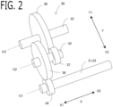
- FIG. 2 is an oblique drawing of the schematic configuration of the reduction gear 30.
- FIG. 3 is an oblique drawing of the electric drive apparatus 1.
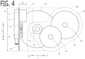
- FIG. 4 is a perspective drawing of the electric drive apparatus 1 viewed on the other side in the axial direction X2.
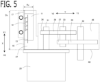
- FIG. 5 is a perspective drawing of the electric drive apparatus 1 viewed on one side in the second orthogonal direction Z1.
- the electric drive apparatus 1 is provided with an inverter circuit 10, a rotary electric machine 20, a reduction gear 30, a case 40 and the like.
- a direction parallel to an axial center C1 of a rotor rotation shaft 23 of the rotary electric machine 20 is defined as an axial direction X.
- One side in the axial direction X1, and the other side in the axial direction X2 which is the opposite side of the one side in the axial direction X1 are defined.
- a specific direction which is orthogonal to the axial direction X is defined as a first orthogonal direction Y.
- One side in the first orthogonal direction Y1, and the other side in the first orthogonal direction Y2 which is the opposite side of the one side in the first orthogonal direction Y1 are defined.
- a direction which is orthogonal to the axial direction X and the first orthogonal direction Y is defined as a second orthogonal direction Z.
- One side in the second orthogonal direction Z1, and the other side of the second orthogonal direction Z2 which is the opposite side of the one side in the second orthogonal direction Z1 are defined.
- the rotary electric machine 20 is provided with a stator 21, a rotor 22, and a rotor rotation shaft 23 integrally rotating with the rotor 22.
- the rotary electric machine 20 is provided with a winding 24 to which AC power converted by the inverter circuit 10 is supplied.
- the winding 24 is wound around the stator 21.
- three-phase windings 24 of U phase, V phase, and W phase are provided.
- the phase number may be other than three-phase, and a plurality of sets of three-phase windings may be provided.
- the rotary electric machine 20 is a permanent magnet type synchronous rotary electric machine in which the permanent magnet is provided in the rotor 20.
- the AC rotary machine 20 may be a field winding type synchronous rotary electric machine with an electromagnet in the rotor 22, or may be an induction rotary electric machine with an iron core in the rotor 22.
- the rotary electric machine 20 can perform one or both of power running and power generation.
- the rotary electric machine 20 performs the power running by the AC power supplied from the inverter circuit 10, or the rotary electric machine 20 supplies the generated AC power to the inverter circuit 10.
- the components of the rotary electric machine 20, such as the stator 21, the rotor 22, the rotor rotation shaft 23, and the winding 24 are housed in a motor case 25.
- the part on one side in the axial direction X1 and the part on the other side in the axial direction X2 of the rotor rotation shaft 23 are rotatably supported by the motor case 25 via the bearings 26.
- the rotor rotation shaft 23 penetrated a side wall on the one side in the axial direction X1 of the motor case 25, and projects to the one side in the axial direction X1.
- the inverter circuit 10 is a power conversion circuit which converts between DC power and AC power.
- the inverter circuit 10 is provided with a smoothing capacitor 11, a power semiconductor circuit 12, and a circuit board 13.
- the inverter circuit 10 converts between the DC power and the AC power of three-phase.
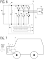
- FIG. 6 shows the circuit diagram of the inverter circuit 10.
- the inverter circuit 10 is provided with three sets of series circuits (leg) in each of which a high potential side switching device SP connected to a high potential side bus line BP and a low potential side switching device SN connected to a low potential side bus line BN are connected in series, corresponding to each phase of three-phase.
- a connection node of two switching devices in the series circuit of each phase is connected to the winding 24 of the corresponding phase via a connection wiring 18 described below.
- the high potential side bus line BP is connected to a high potential side of a DC power source 60 which is outside of the electric drive apparatus 1, and the low potential side bus line BN is connected to a low potential side of the outside DC power source 60.
- the switching device is the power semiconductor circuit 12, and IGBT (Insulated Gate Bipolar Transistor), MOSFET (Metal Oxide Semiconductor Field Effect Transistor), or the like is used.
- IGBT Insulated Gate Bipolar Transistor
- MOSFET Metal Oxide Semiconductor Field Effect Transistor
- the switching device is modularized arbitrarily.
- the smoothing capacitor 11 is connected between the high potential side bus line BP and the low potential side bus line BN.
- the circuit board 13 is provided with a gate driving circuit 14 which outputs an on/off signal to a gate terminal of each switching device according to an on/off command value of each switching signal outputted from the control circuit 15.
- the circuit board 13 is provided with the control circuit 15 which outputs the on/off command value of the switching device to each gate driving circuit.
- the control circuit 15 calculates an AC voltage command value of each phase, and the like, and outputs the on/off command value of each switching signal of each phase.
- the control circuit 15 may be provided outside the inverter circuit 10, or outside the electric drive apparatus 1.
- the reduction gear 30 reduces and outputs a rotational speed of the rotor rotation shaft 23.
- the reduction gear 30 is provided with a plurality of rotation shafts arranged in parallel with the axial direction X of the rotor rotation shaft 23, and a plurality of gears.
- the plurality of rotation shafts include an input rotation shaft 31 extending on coaxially from the rotor rotation shaft 23 to one side in the axial direction X1, and rotating integrally with the rotor rotation shaft 23, and an output rotation shaft 32 outputting rotation to outside of the reduction gear 30.
- the reduction gear 30 is provided with a differential gear DF.
- two output shafts OS1, OS2 on one side and the other side in the axial direction X1, X2 of the differential gear DF (hereinafter, referred to as a first differential output shaft OS1 and a second differential output shaft OS2) are the output rotation shafts 32.
- the differential gear DF is provided with an output input gear 35 rotatable around an axial center C3 of the first and second differential output shafts (the output rotation shafts 32), a carrier CA rotating integrally with the output input gear 35, a pinion rotation shaft PS rotating integrally with the carrier CA and orthogonal to the axial center C3 of the output rotation shaft 32, a pair of pinion gears PG rotatable around the pinion rotation shaft PS, a first output gear OG1 engaging with the pinion gear PG and rotating integrally with the first differential output shaft OS1, and a second output gear OG2 engaging with the pinion gear PG and rotating integrally with the second differential output shaft OS2.
- the pinion rotation shaft PS, the pinion gear PG, the first and second output gears OG1, OG2 are housed inside the carrier CA.
- the reduction gear 30 may not be provided with the differential gear DF.
- the output input gear 35 and the output rotation shaft 32 may be configured to rotate integrally.
- FIG. 1 shows the case where the differential gear DF is not provided but the output input gear 35 and the output rotation shaft 32 is configured to rotate integrally.
- the output rotation shaft 32 penetrates and projects the case 40 (the first case 41) to the other side in the axial direction X2, and does not penetrate the case 40 to one side in the axial direction X1.
- One intermediate rotation shaft 33 is provided as a rotation shaft of the reduction gear 30 for transmitting rotation between the input rotation shaft 31 and the output rotation shaft 32.
- the axial center C1 of the input rotation shaft 31, the axial center C2 of the intermediate rotation shaft 33, and the axial center C3 of the output rotation shaft 32 are parallel with each other.
- An input output gear 34 rotating integrally with the input rotation shaft 31 is provided.
- An intermediate input gear 36 engaging with the input output gear 34 of the input rotation shaft 31 and rotating integrally with the intermediate rotation shaft 33 is provided.
- An intermediate output gear 37 rotating integrally with the intermediate rotation shaft 33 is provided.
- the teeth number and the diameter of the intermediate input gear 36 are larger than the teeth number and the diameter of the input output gear 34.
- the teeth number and the diameter of the intermediate output gear 37 are smaller than the teeth number and the diameter of the intermediate input gear 36.
- the teeth number and the diameter of the output input gear 35 are larger than the teeth number and the diameter of the intermediate output gear 37. Accordingly, the reduction gear 30 reduces in two steps.
- the positions of the plurality of rotation shafts (in this example, the input rotation shaft 31, the intermediate rotation shaft 33, the output rotation shaft 32) of the reduction gear 30 in the axial direction X have mutually overlapping parts.
- the parts on one side in the axial direction X1 of the plurality of rotation shafts 31, 32, 33 of the reduction gear 30 are rotatably supported by the first case member 41 via the bearings 34.
- the parts on the other side in the axial direction X2 of the plurality of rotation shafts 31, 32, 33 of the reduction gear 30 are rotatably supported by the second case member 42 via the bearings 34.
- the input output gear 34 and the intermediate input gear 36 are arranged on one side in the axial direction X1 than the central part of the reduction gear 30 in the axial direction X.
- the intermediate output gear 37 and the output input gear 35 are arranged on the other side in the axial direction X2 than the central part of the reduction gear 30 in the axial direction X.
- the intermediate rotation shaft 33 may not be provided as the rotation shaft of the reduction gear 30. And, the input output gear 34 and the output input gear 35 may be engaged, or a plurality of intermediate rotation shafts may be provided.
- the input rotation shaft 31 and the rotor rotation shaft 23 may be formed integrally.
- Various reduction gear configurations which reduce and output the rotational speed of the rotor rotation shaft 23 may be used as the reduction gear 30.
- the case 40 houses the reduction gear 30 at least.
- the case 40 is provided with a second case member 42 with a bottomed tubular reduction gear housing opening part 45 opened to the one side in the axial direction X1, and a first case member 41 closing an opening of the reduction gear housing opening part 45.
- the reduction gear 30 is housed in a reduction gear housing space 46 formed by the reduction gear housing opening part 45 of the second case member 42, and the first case member 41.
- the second case member 42 covers the part on the other side in the axial direction X2 of the reduction gear 30.
- the parts on the other side in the axial direction X2 of the plurality of rotation shafts of the reduction gear 30 are rotatably supported via the bearings 34.
- the first case member 41 covers the part on the one side in the axial direction X1 of the reduction gear 30.
- the parts on the one side in the axial direction X1 of the plurality of rotation shafts of the reduction gear 30 are rotatably supported via the bearings 34.
- the second case member 42 is provided with a bottomed tubular reduction gear housing opening part 45 opened to the one side in the axial direction X1.
- a bottom wall 45a on the other side in the axial direction X2 of the reduction gear housing opening part 45 of the second case member 42 rotatably supports the parts on the other side in the axial direction X2 of the plurality of rotation shafts of the reduction gear 30 via the bearings 34.
- the bottom wall 45a is provided with a through hole through which the input rotation shaft 31 penetrates to the other side in the axial direction X2, and a through hole through which the output rotation shaft 32 (the second differential output shaft OS2) penetrates to the other side in the axial direction X2.
- the rotary electric machine 20 is arranged on the other side in the axial direction X2 of the second case member 42.
- the end on the one side in the axial direction X1 of the motor case 25 of the rotary electric machine 20 is fixed to the end on the other side in the axial direction X2 of the second case member 42 by a fastening member such as a bolt.
- the second case member 42 and the motor case 25 may be formed integrally.
- the rotation shafts of the reduction gear 30 other than the input rotation shaft 31 are arranged on the one side in the first orthogonal direction Y1 than the input rotation shaft 31, a space where each part of the reduction gear 30 is not arranged is formed in a space which is on the radial-direction outside of the input rotation shaft 31 except the one side in the first orthogonal direction Y1 of the input rotation shaft 31, and overlaps with the rotary electric machine 20 when viewed in the axial direction X.
- the inverter circuit 10 can be arranged in this space, and the electric drive apparatus 1 can be miniaturized.
- the inverter circuit 10 is arranged outside the reduction gear housing space 46, the reduction gear and the inverter circuit need not be assembled in the case at the same time like the patent document 2. That is, when the reduction gear housing opening part 45 of the second case member 42 and the first case member 41 are fitted, and the reduction gear 30 is attached to the reduction gear housing space 46, it is not necessary to attach the inverter circuit 10. Accordingly, the lubricating oil of the reduction gear and the like can be prevented from mixing in the inverter circuit 10. The degree of freedom of assembly is enhanced, and workability and productivity are improved.
- the input rotation shaft 31, the intermediate rotation shaft 33, and the output rotation shaft 32 are arranged in this order on the one side in the first orthogonal direction Y1.
- the intermediate rotation shaft 33 is arranged on the one side in the first orthogonal direction Y1 and the other side in the second orthogonal direction Z2 of the input rotation shaft 31.
- the output rotation shaft 32 is arranged on the one side in the first orthogonal direction Y1 and the one side in the second orthogonal direction Z1 of the intermediate rotation shaft 33.
- the first orthogonal direction Y is within a range of a direction where other rotation shafts are arranged with respect to the input rotation shaft 31, it may deviate from the illustrated direction.
- the reduction gear housing opening part 45 of the second case member 42 and the first case member 41 cover the radial-direction outside (around) of the input rotation shaft 31 except the one side in the first orthogonal direction Y1 of the input rotation shaft 31. Accordingly, on the radial-direction outside of the input rotation shaft 31 except the one side in the first orthogonal direction Y1 of the input rotation shaft 31, there is a space via the reduction gear housing opening part 45 of the second case member 42, and the first case member 41.
- the inverter circuit 10 is arranged utilizing this space.
- the inverter circuit 10 is arranged on the other side in the first orthogonal direction Y2 of the input rotation shaft 31. According to this configuration, since each part of the reduction gear 30 is arranged on the one side in the first orthogonal direction Y1 of the input rotation shaft 31, and the inverter circuit 10 is arranged on the other side in the first orthogonal direction Y2 of the input rotation shaft 31, weight can be balanced between the one side Y1 and the other side Y2 in the first orthogonal direction of the input rotation shaft 31.
- the case 40 is provided with the inverter housing opening part 47 which is an opening part which houses the inverter circuit 10, and the opening of the inverter housing opening part 47 is closed by a member other than the first case member 41.
- the inverter circuit 10 can be attached into the inverter housing opening part 47 in a clean room and the like, separately from the reduction gear 30, and a foreign matter can be prevented from mixing into the inverter circuit 10.
- the inverter housing opening part 47 is formed in the second case member 42. An inner space of the inverter housing opening part 47 and the reduction gear housing space 46 are not communicated.
- the inverter housing opening part 47 may be formed in a case member which is a body different from the first case member 41 and the second case member 42.
- the opening of the inverter housing opening part 47 is closed by a housing 16 of the inverter circuit 10 described below. According to this configuration, by inserting each part of the inverter circuit 10 inside the inverter housing opening part 47, fitting the housing 16 of the inverter circuit 10 to the opening of the inverter housing opening part 47, and fixing by a fastening member such as a bolt, the inverter circuit 10 can be attached easily.
- the inverter housing opening part 47 opens to the other side in the first orthogonal direction Y2 on the other side in the first orthogonal direction Y2 of the input rotation shaft 31.
- the inverter circuit 10 is housed inside the inverter housing opening part 47.
- the inverter circuit 10 since the inverter circuit 10 is arranged on the other side in the first orthogonal direction Y2 of the input rotation shaft 31, and the inverter housing opening part 47 opens to the same other side in the first orthogonal direction Y2, the inverter circuit 10 can be easily attached from the other side in the first orthogonal direction Y2. Since the one side in the axial direction X1 which is an opening direction of the reduction gear housing opening part 45, and the other side in the first orthogonal direction Y2 which is an opening direction of the inverter housing opening part 47 are orthogonal, an attaching direction of the reduction gear 30 and an attaching direction of the inverter circuit 10 can be orthogonal, and the workability of attachment can be improved.
- the inverter housing opening part 47 is provided with an overlap extension part 47a formed by extending from the reduction gear housing opening part 45, on the other side in the first orthogonal direction Y2 of the reduction gear housing opening part 45 of the second case member 42, and an outside extension part 47b formed by extending from the reduction gear housing opening part 45 of the second case member 42 on the other side in the first orthogonal direction Y2 of the first case member 41.
- the inner space of the inverter housing opening part 47 and the reduction gear housing space 46 are separated by a circumferential wall 45b of the reduction gear housing opening part 45, and the like.
- the inverter housing opening part 47 can be provided at the position on the other side in the first orthogonal direction Y2 of the reduction gear housing opening part 45 of the second case member 42. Further, by providing the outside extension part 47b, the inverter housing opening part 47 can be expanded to the one side in the axial direction X1 until the position on the other side in the first orthogonal direction Y2 of the first case member 41, that is, the position on the one side in the axial direction X1 of the first case member 41 where the reduction gear housing opening part 45 of the second case member 42 is not arranged.
- the space on the other side in the first orthogonal direction Y2 of the reduction gear housing space 46 can be used effectively, the inverter housing opening part 47 wide in the axial direction X can be provided, and the enlargement of apparatus can be suppressed.
- the position in the second orthogonal direction Z of the inverter housing opening part 47 expands to the one side Z1 and the other side Z2 in the second orthogonal direction than the position in the second orthogonal direction Z of the input rotation shaft 31.
- the inverter housing opening part 47 wide in the second orthogonal direction Z can be provided, and the enlargement of apparatus can be suppressed.
- a width Dy in the first orthogonal direction Y of the inverter circuit 10 is shorter than a width Dz in the second orthogonal direction Z and a width Dx in the axial direction X of the inverter circuit 10.
- a space on the other side in the first orthogonal direction Y2 of the reduction gear housing space 46 is widely used in the second orthogonal direction Z and the axial direction X, the width Dy in the first orthogonal direction Y of the inverter circuit 10 can be narrowed, a projection width of the inverter circuit 10 to the other side in the first orthogonal direction Y2 can be reduced, and the enlargement of apparatus can be suppressed.
- the smoothing capacitor 11 may have a larger volume and a larger thickness than other components, in order to smooth current at the time of energization of a large current. Accordingly, the arrangement of the smoothing capacitor 11 becomes a problem.
- the position in the second orthogonal direction Z of the smoothing capacitor 11 is arranged on the one side in the second orthogonal direction Z1 than the position in the second orthogonal direction Z of the input rotation shaft 31.
- the position in the second orthogonal direction Z of the smoothing capacitor 11 may be arranged on the other side in the second orthogonal direction Z2 than the position in the second orthogonal direction Z of the input rotation shaft 31.
- the positions in the second orthogonal direction Z of the power semiconductor circuit 12 and the circuit board 13 overlap with the position in the second orthogonal direction Z of the input rotation shaft 31.
- the width in the first orthogonal direction Y of the smoothing capacitor is longer than the width in the first orthogonal direction Y of the power semiconductor circuit 12 and the circuit board 13.
- the smoothing capacitor 11 is projected to the one side in the first orthogonal direction Y1 than the power semiconductor circuit 12 and the circuit board 13.
- the smoothing capacitor 11 is arranged corresponding to a space on the one side in the second orthogonal direction Z1 of the input rotation shaft 31
- the power semiconductor circuit 12 and the circuit board 13 can be arranged corresponding to a space on the other side in the first orthogonal direction Y2 of the input rotation shaft 31.
- the inverter circuit 10 can be arranged on the one side in the first orthogonal direction Y1 so as to be close to the input rotation shaft 31.
- the projection width of the inverter circuit 10 to the other side in the first orthogonal direction Y2 can be reduced, and the enlargement of apparatus can be suppressed.
- the inverter circuit 10 is arranged on the one side in the axial direction X1 than the rotary electric machine 20, and has a part which overlaps with the rotary electric machine 20 when viewed in the axial direction X.
- the connection wiring 18 extends from the inverter circuit 10 to the other side in the axial direction X2, penetrates a wall between the inverter circuit 10 and the rotary electric machine 20, and is connected to the winding 24. According to this configuration, the length of the connection wiring 18 can be shortened.
- the wall between the inverter circuit 10 and the rotary electric machine 20 is composed of the wall on the other side in the axial direction X2 of the inverter housing opening part 47, and the wall on the one side in the axial direction X1 of the motor case 25.
- the inverter circuit 10 is provided with the housing 16 which has a surface facing the one side in the first orthogonal direction Y1.
- the smoothing capacitor 11, the power semiconductor circuit 12, and the circuit board 13 are fixed to the surface on the one side in the first orthogonal direction Y1 of the housing 16.
- the housing 16 closes the opening of the inverter housing opening part 47.
- the inverter circuit 10 can be attached easily.
- the housing 16 is formed in a plate shape (in this example, rectangular plate shape) long in the second orthogonal direction Z and the axial direction X.
- the inverter circuit 10 is provided with a water-cooled cooler 17.
- the water-cooled cooler 17 is fixed to a surface on the other side in the first orthogonal direction Y2 of the housing 16, and each part of the inverter circuit 10 is cooled via the housing 16.
- the cooler 17 may be provided inside the housing 16.
- the other side in the first orthogonal direction Y2 may face the forward side of the vehicle.
- the vehicle 50 is provided with a radiator 51 cooling a cooling water supplied to the cooler 17, in the front part of the vehicle.
- the cooler 17 can be arranged close to the radiator 51, and a piping 52 of cooling water can be shortened.
- the other side in the first orthogonal direction Y2 may face the backward side of the vehicle. According to this configuration, since the inverter circuit 10 is arranged on the backward side of the electric drive apparatus 1, when the vehicle collides forward, the inverter circuit 10 can be prevented from collapsing, and the danger such as the electric leakage can be reduced.
- the other side in the first orthogonal direction Y2 may face the upper side of the vehicle.
- Embodiment 2 Next, the electric drive apparatus 1 according to Embodiment 2 will be explained. The explanation for constituent parts the same as those in Embodiment 1 will be omitted.
- the basic configuration of the electric drive apparatus 1 according to the present embodiment is the same as that of Embodiment 1.
- Embodiment 2 is different from Embodiment 1 in the arrangement of the inverter circuit 10, and the like.
- FIG. 8 is an oblique drawing of the electric drive apparatus 1 according to the present embodiment.
- FIG. 9 is a perspective drawing of the electric drive apparatus 1 on one side in the second orthogonal direction Z1.
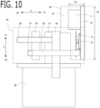
- FIG. 10 is a perspective drawing of the electric drive apparatus 1 viewed on the other side in the first orthogonal direction Y2.
- one or more of the rotation shafts (in this example, the output rotation shaft 32, the intermediate rotation shaft 33) of the reduction gear 30 other than the input rotation shaft 31 are arranged on the one side in the first orthogonal direction Y1 than the input rotation shaft 31.
- the inverter circuit 10 is arranged outside the reduction gear housing space 46, and on the radial-direction outside of the input rotation shaft except the one side in the first orthogonal direction Y1 of the input rotation shaft 31; and is arranged on the one side in the axial direction X1 than the rotary electric machine 20, and has a part overlapping with the rotary electric machine 20 when viewed in the axial direction X.
- the inverter circuit 10 is arranged on the one side in the second orthogonal direction Z1 of the input rotation shaft 31.
- the inverter circuit 10 can be arranged utilizing this space.
- the intermediate rotation shaft 33 is arranged on the one side in the first orthogonal direction Y1 and the other side in the second orthogonal direction Z2 of the input rotation shaft 31.
- a space on the one side in the second orthogonal direction Z1 of the input rotation shaft 31 becomes wider than a space on the other side in the second orthogonal direction Z2, and the arrangement space of the inverter circuit 10 can be widened.
- the inverter housing opening part 47 is formed in a case member (the inverter case 48) which is a body different from the first case member 41 and the second case member 42.
- the inverter case 48 is fixed to the second case member 42 or the motor case 25 by a fastening member such as a bolt.
- the second case member 42 is provided with a side wall 45c which extends to the other side in the first orthogonal direction Y2 from a bottom wall 45a on the other side in the axial direction X2 of the reduction gear housing opening part 45. And, the end on the other side in the axial direction X2 of the inverter case 48 is fixed to the end on the one side in the axial direction X1 of the side wall 45c of the second case member 42 by a fastening member.
- the inverter housing opening part 47 may be formed in the second case member 42.
- the inverter housing opening part 47 may be formed to extend to the one side in the axial direction X1 from the side wall 45c of the second case member 42.
- the inverter housing opening part 47 opens to the one side in the second orthogonal direction Z1, on the one side in the second orthogonal direction Z1 of the input rotation shaft 31.
- the inverter circuit 10 is housed inside the inverter housing opening part 47.
- the inverter circuit 10 since the inverter circuit 10 is arranged on the one side in the second orthogonal direction Z1 of the input rotation shaft 31, and the inverter housing opening part 47 opens to the same one side in the second orthogonal direction Z1, the inverter circuit 10 can be easily attached from the one side in the second orthogonal direction Z1. Since the one side in the axial direction X1 which is an opening direction of the reduction gear housing opening part 45, and the one side in the second orthogonal direction Z1 which is an opening direction of the inverter housing opening part 47 are orthogonal, an attaching direction of the reduction gear 30 and an attaching direction of the inverter circuit 10 can be orthogonal, and the workability of attachment can be improved.
- the inverter housing opening part 47 is provided with a part arranged on the one side in the second orthogonal direction Z1 of the reduction gear housing opening part 45 of the second case member 42, and a part arranged on the one side in the second orthogonal direction Z1 of the first case member 41.
- the inverter housing opening part 47 can be expanded to the one side in the axial direction X1 until the position on the one side in the axial direction X1 of the first case member 41 where the reduction gear housing opening part 45 of the second case member 42 is not arranged. Accordingly, even if the first case member 41 is configured to close the reduction gear housing opening part 45 of the second case member 42, by using effectively a space on the one side in the second orthogonal direction Z1 of the input rotation shaft 31, the inverter housing opening part 47 wide in the axial direction X can be provided, and the enlargement of apparatus can be suppressed.
- the position in the first orthogonal direction Y of the inverter housing opening part 47 expands to the one side Y1 and the other side Y2 in the first orthogonal direction than the position of the input rotation shaft 31 in the first orthogonal direction Y.
- the inverter housing opening part 47 wide in the first orthogonal direction Y can be provided, and the enlargement of apparatus can be suppressed.
- a width Dz of the inverter circuit 10 in the second orthogonal direction Z is shorter than a width Dy in the first orthogonal direction Y and a width Dx in the axial direction X of the inverter circuit 10.
- a space on the one side in the second orthogonal direction Z1 of the input rotation shaft 31 is widely used in the first orthogonal direction Y and the axial direction X, the width Dz of the inverter circuit 10 in the second orthogonal direction Z can be narrowed, the projection width of the inverter circuit 10 to the one side in the second orthogonal direction Z1 can be reduced, and the enlargement of apparatus can be suppressed.
- the position of the smoothing capacitor 11 in the axial direction X is arranged on the one side X1 of the axial direction X than the position of the input rotation shaft 31 in the axial direction X.
- the positions of the power semiconductor circuit 12 and the circuit board 13 in the axial direction X overlap with the position of the input rotation shaft 31 in the axial direction X.
- the width of the smoothing capacitor 11 in the second orthogonal direction Z is longer than the widths of the power semiconductor circuit 12 and the circuit board 13 in the second orthogonal direction Z, and the smoothing capacitor 11 is projected to the other side in the second orthogonal direction Z2 than the power semiconductor circuit 12 and the circuit board 13.
- the smoothing capacitor 11 is arranged corresponding to a space on the one side in the axial direction X1 of the input rotation shaft 31, and the power semiconductor circuit 12 and the circuit board 13 can be arranged corresponding to a space on the one side in the second orthogonal direction Z1 of the input rotation shaft 31. Accordingly, the inverter circuit 10 can be arranged on the other side in the second orthogonal direction Z2 so as to be close to the input rotation shaft 31. Accordingly, the projection width of the inverter circuit 10 to the one side in the second orthogonal direction Z1 can be reduced, and the enlargement of apparatus can be suppressed. Since the smoothing capacitor 11 is arranged on the opposite side of the rotary electric machine 20 interposing the reduction gear 30, weights in the axial direction X can be balanced.
- the inverter circuit 10 is arranged on the one side in the axial direction X1 than the rotary electric machine 20, and has a part which overlaps with the rotary electric machine 20 when viewed in the axial direction X.
- the connection wiring 18 extends from the inverter circuit 10 to the other side in the axial direction X2, penetrates a wall between the inverter circuit 10 and the rotary electric machine 20, and is connected to the winding 24. According to this configuration, the length of the connection wiring 18 can be shortened.
- the wall between the inverter circuit 10 and the rotary electric machine 20 is composed of the wall on the other side in the axial direction X2 of the inverter housing opening part 47, and the wall on the one side in the axial direction X1 of the motor case 25.
- the inverter circuit 10 is provided with the housing 16 which has a surface facing the other side in the second orthogonal direction Z2.
- the smoothing capacitor 11, the power semiconductor circuit 12, and the circuit board 13 are fixed to the surface on the other side in the second orthogonal direction Z2 of the housing 16.
- the housing 16 closes the opening of the inverter housing opening part 47.
- the inverter circuit 10 can be assembled easily.
- the housing 16 is formed in a plate shape (in this example, rectangular plate shape) long in the first orthogonal direction Y and the axial direction X.
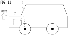
- the one side in the second orthogonal direction Z1 may face the upper side of the vehicle 50.
- the inverter circuit 10 can be protected from the stepping stone from the road surface, and the like.
- the inverter circuit 10 and the vehicle side connector can be connected from the upper side of the vehicle, and the workability and the productivity can be improved. After attaching to the vehicle, the inverter circuit 10 can be easily maintained from the upper side of the vehicle.
- the water-cooled cooler 17 may be provided in the inverter circuit 10, and the water-cooled cooler 17 may be fixed to the surface on the one side in the second orthogonal direction Z1 of the housing 16. Alternatively, the cooler 17 may be provided inside the housing 16.
- the other side in the first orthogonal direction Y2 may face the forward side of the vehicle.
- the cooler 17 can be arranged close to the radiator 51.
- the other side in the first orthogonal direction Y2 may face the backward side of the vehicle. Since the inverter circuit 10 is arranged on the backward side of the electric drive apparatus 1, when the vehicle collides a forward object, the inverter circuit 10 can be protected, and the danger such as the electric leakage can be reduced.
Landscapes
- Engineering & Computer Science (AREA)
- Power Engineering (AREA)
- Chemical & Material Sciences (AREA)
- Combustion & Propulsion (AREA)
- Transportation (AREA)
- Mechanical Engineering (AREA)
- Microelectronics & Electronic Packaging (AREA)
- Connection Of Motors, Electrical Generators, Mechanical Devices, And The Like (AREA)
- Gear Transmission (AREA)
Abstract
Description
- The present disclosure relates to an electric drive apparatus.
- Recently, in consideration of environmental problems such as global warming, the electrification of the vehicle is rapidly progressing, replacing the conventional vehicle powered by the internal combustion engine with a system driven by the rotary electric machine which does not emit carbon dioxide during driving. The electric drive apparatus requires not only the rotary electric machine but also the reduction gear which reduces the rotational speed of the rotary electric machine, and the inverter circuit which converts between DC power and AC power.
- There has been proposed an apparatus which integrates and miniaturizes these rotary electric machines, reduction gear, and inverter circuit, which have conventionally been manufactured individually and connected to each other.
-
- Patent document 1:
JP 5900012 B - Patent document 2:
WO 2019/152372 A - For example, in
patent document 1, the connecting part between the output rotation shaft of the reduction gear and the wheel axle can be arranged in the c right and left enter of the vehicle as much as possible, the inverter circuit is arranged on the opposite side of the rotary electric machine interposing the reduction gear. However, since the reduction gear is interposed between the rotary electric machine and the inverter circuit, the connection lines (the bus bars which connect the power lines, and the sensor signal lines for the rotary electric machine control) between the rotary electric machine and the inverter circuit become long, there are problems in terms of efficiency, cost, and noise resistance. - In patent document 2, although the distance between the rotary electric machine and the inverter circuit is brought close, it is necessary to assemble the reduction gear and the inverter circuit inside the case at the same time. Accordingly, the lubricating oil of the reduction gear and the like may be mixed in the inverter circuit. There is a problem that the degree of freedom of the assembly is low, and the workability and the productivity are deteriorated.
- Then, the purpose of the present disclosure is to provide an electric drive apparatus capable of miniaturizing the apparatus by the arrangement of the inverter circuit, and assembling the inverter circuit to the apparatus separately from the reduction gear.
- An electric drive apparatus according to present disclosure, including:
- an inverter circuit that converts between DC power and AC power;
- a rotary electric machine that is provided with a winding to which AC power converted by an inverter circuit is supplied, and a rotor rotation shaft rotating integrally with a rotor;
- a reduction gear that reduces and outputs the rotational speed of the rotor rotation shaft; and
- a case that houses at least the reduction gear,
- wherein the reduction gear is provided with at least a plurality of rotation shafts arranged in parallel with an axial direction of the rotor rotation shaft, and a plurality of gears,
- the plurality of rotation shafts includes an input rotation shaft extending on coaxially from the rotor rotation shaft to one side in the axial direction, and rotating integrally with the rotor rotation shaft, and an output rotation shaft outputting rotation to outside of the reduction gear,
- the case is provided with a second case member with a bottomed tubular reduction gear housing opening part opened to the one side in the axial direction, and a first case member closing an opening of the reduction gear housing opening part,
- the reduction gear is housed in a reduction gear housing space formed by the reduction gear housing opening part of the second case member and the first case member,
- defining a specific direction orthogonal to the axial direction as a first orthogonal direction, one or more of the rotation shafts other than the input rotation shaft are arranged on one side in the first orthogonal direction than the input rotation shaft,
- the inverter circuit is arranged outside the reduction gear housing space, and on a radial-direction outside of the input rotation shaft except the one side in the first orthogonal direction of the input rotation shaft; and is arranged on the one side in the axial direction than the rotary electric machine, and has a part which overlaps with the rotary electric machine when viewed in the axial direction.
- According to the electric drive apparatus of the present disclosure, since one or more of the rotation shafts of the reduction gear other than the input rotation shaft are arranged on the one side in the first orthogonal direction than the input rotation shaft, a space where each part of the reduction gear is not arranged is formed in a space which is on the radial-direction outside of the input rotation shaft except the one side in the first orthogonal direction of the input rotation shaft, and overlaps with the rotary electric machine when viewed in the axial direction. The inverter circuit can be arranged in this space, and the electric drive apparatus can be miniaturized. Since the inverter circuit is arranged outside the reduction gear housing space, the reduction gear and the inverter circuit need not be assembled in the case at the same time like the patent document 2. That is, when the reduction gear housing opening part of the second case member and the first case member are fitted, and the reduction gear is assembled to the reduction gear housing space, it is not necessary to assemble the inverter circuit. Accordingly, the lubricating oil of the reduction gear and the like can be prevented from mixing in the inverter circuit. The degree of freedom of assembly is enhanced, and workability and productivity are improved.
-
-
FIG. 1 is a skeleton diagram showing the schematic configuration of the electric drive apparatus according toEmbodiment 1; -
FIG. 2 is an oblique drawing of the schematic configuration of the reduction gear according toEmbodiment 1; -
FIG. 3 is an oblique drawing of the electric drive apparatus according toEmbodiment 1; -
FIG. 4 is a perspective drawing of the electric drive apparatus viewed on the other side in the axial direction, according toEmbodiment 1; -
FIG. 5 is a perspective drawing of the electric drive apparatus viewed on one side in the second orthogonal direction, according to Embodiment 1; -
FIG. 6 is a schematic circuit diagram of the inverter circuit according toEmbodiment 1; -
FIG. 7 is a figure explaining the direction of the electric drive apparatus mounted on the vehicle according toEmbodiment 1; -
FIG. 8 is an oblique drawing of the electric drive apparatus according to Embodiment 2; -
FIG. 9 is a perspective drawing of the electric drive apparatus viewed on one side in the second orthogonal direction, according to Embodiment 2; -
FIG. 10 is a perspective drawing of the electric drive apparatus viewed on the other side in the first orthogonal direction, according to Embodiment 2; and -
FIG. 11 is a figure explaining the direction of the electric drive apparatus mounted on the vehicle according to Embodiment 2. - An
electric drive apparatus 1 according toEmbodiment 1 will be explained with reference to drawings.FIG. 1 is a skeleton diagram showing a schematic configuration of theelectric drive apparatus 1.FIG. 2 is an oblique drawing of the schematic configuration of thereduction gear 30.FIG. 3 is an oblique drawing of theelectric drive apparatus 1.FIG. 4 is a perspective drawing of theelectric drive apparatus 1 viewed on the other side in the axial direction X2.FIG. 5 is a perspective drawing of theelectric drive apparatus 1 viewed on one side in the second orthogonal direction Z1. - The
electric drive apparatus 1 is provided with aninverter circuit 10, a rotaryelectric machine 20, areduction gear 30, acase 40 and the like. - In the present disclosure, a direction parallel to an axial center C1 of a
rotor rotation shaft 23 of the rotaryelectric machine 20 is defined as an axial direction X. One side in the axial direction X1, and the other side in the axial direction X2 which is the opposite side of the one side in the axial direction X1 are defined. A specific direction which is orthogonal to the axial direction X is defined as a first orthogonal direction Y. One side in the first orthogonal direction Y1, and the other side in the first orthogonal direction Y2 which is the opposite side of the one side in the first orthogonal direction Y1 are defined. A direction which is orthogonal to the axial direction X and the first orthogonal direction Y is defined as a second orthogonal direction Z. One side in the second orthogonal direction Z1, and the other side of the second orthogonal direction Z2 which is the opposite side of the one side in the second orthogonal direction Z1 are defined. - The rotary
electric machine 20 is provided with astator 21, arotor 22, and arotor rotation shaft 23 integrally rotating with therotor 22. The rotaryelectric machine 20 is provided with a winding 24 to which AC power converted by theinverter circuit 10 is supplied. The winding 24 is wound around thestator 21. In the present embodiment, three-phase windings 24 of U phase, V phase, and W phase are provided. The phase number may be other than three-phase, and a plurality of sets of three-phase windings may be provided. - In the present embodiment, the rotary
electric machine 20 is a permanent magnet type synchronous rotary electric machine in which the permanent magnet is provided in therotor 20. The ACrotary machine 20 may be a field winding type synchronous rotary electric machine with an electromagnet in therotor 22, or may be an induction rotary electric machine with an iron core in therotor 22. - The rotary
electric machine 20 can perform one or both of power running and power generation. The rotaryelectric machine 20 performs the power running by the AC power supplied from theinverter circuit 10, or the rotaryelectric machine 20 supplies the generated AC power to theinverter circuit 10. - The components of the rotary
electric machine 20, such as thestator 21, therotor 22, therotor rotation shaft 23, and the winding 24 are housed in amotor case 25. The part on one side in the axial direction X1 and the part on the other side in the axial direction X2 of therotor rotation shaft 23 are rotatably supported by themotor case 25 via thebearings 26. Therotor rotation shaft 23 penetrated a side wall on the one side in the axial direction X1 of themotor case 25, and projects to the one side in the axial direction X1. - The
inverter circuit 10 is a power conversion circuit which converts between DC power and AC power. Theinverter circuit 10 is provided with a smoothingcapacitor 11, apower semiconductor circuit 12, and acircuit board 13. - In the present embodiment, the
inverter circuit 10 converts between the DC power and the AC power of three-phase.FIG. 6 shows the circuit diagram of theinverter circuit 10. Theinverter circuit 10 is provided with three sets of series circuits (leg) in each of which a high potential side switching device SP connected to a high potential side bus line BP and a low potential side switching device SN connected to a low potential side bus line BN are connected in series, corresponding to each phase of three-phase. A connection node of two switching devices in the series circuit of each phase is connected to the winding 24 of the corresponding phase via aconnection wiring 18 described below. The high potential side bus line BP is connected to a high potential side of aDC power source 60 which is outside of theelectric drive apparatus 1, and the low potential side bus line BN is connected to a low potential side of the outsideDC power source 60. - The switching device is the
power semiconductor circuit 12, and IGBT (Insulated Gate Bipolar Transistor), MOSFET (Metal Oxide Semiconductor Field Effect Transistor), or the like is used. The switching device is modularized arbitrarily. - The smoothing
capacitor 11 is connected between the high potential side bus line BP and the low potential side bus line BN. Thecircuit board 13 is provided with agate driving circuit 14 which outputs an on/off signal to a gate terminal of each switching device according to an on/off command value of each switching signal outputted from thecontrol circuit 15. Thecircuit board 13 is provided with thecontrol circuit 15 which outputs the on/off command value of the switching device to each gate driving circuit. Thecontrol circuit 15 calculates an AC voltage command value of each phase, and the like, and outputs the on/off command value of each switching signal of each phase. Thecontrol circuit 15 may be provided outside theinverter circuit 10, or outside theelectric drive apparatus 1. - The
reduction gear 30 reduces and outputs a rotational speed of therotor rotation shaft 23. Thereduction gear 30 is provided with a plurality of rotation shafts arranged in parallel with the axial direction X of therotor rotation shaft 23, and a plurality of gears. The plurality of rotation shafts include aninput rotation shaft 31 extending on coaxially from therotor rotation shaft 23 to one side in the axial direction X1, and rotating integrally with therotor rotation shaft 23, and anoutput rotation shaft 32 outputting rotation to outside of thereduction gear 30. - In the present embodiment, as shown in
FIG. 1 , thereduction gear 30 is provided with a differential gear DF. And, two output shafts OS1, OS2 on one side and the other side in the axial direction X1, X2 of the differential gear DF (hereinafter, referred to as a first differential output shaft OS1 and a second differential output shaft OS2) are theoutput rotation shafts 32. The differential gear DF is provided with anoutput input gear 35 rotatable around an axial center C3 of the first and second differential output shafts (the output rotation shafts 32), a carrier CA rotating integrally with theoutput input gear 35, a pinion rotation shaft PS rotating integrally with the carrier CA and orthogonal to the axial center C3 of theoutput rotation shaft 32, a pair of pinion gears PG rotatable around the pinion rotation shaft PS, a first output gear OG1 engaging with the pinion gear PG and rotating integrally with the first differential output shaft OS1, and a second output gear OG2 engaging with the pinion gear PG and rotating integrally with the second differential output shaft OS2. The pinion rotation shaft PS, the pinion gear PG, the first and second output gears OG1, OG2 are housed inside the carrier CA. - The
reduction gear 30 may not be provided with the differential gear DF. Theoutput input gear 35 and theoutput rotation shaft 32 may be configured to rotate integrally. Each figure exceptFIG. 1 shows the case where the differential gear DF is not provided but theoutput input gear 35 and theoutput rotation shaft 32 is configured to rotate integrally. In these figures, theoutput rotation shaft 32 penetrates and projects the case 40 (the first case 41) to the other side in the axial direction X2, and does not penetrate thecase 40 to one side in the axial direction X1. - One
intermediate rotation shaft 33 is provided as a rotation shaft of thereduction gear 30 for transmitting rotation between theinput rotation shaft 31 and theoutput rotation shaft 32. The axial center C1 of theinput rotation shaft 31, the axial center C2 of theintermediate rotation shaft 33, and the axial center C3 of theoutput rotation shaft 32 are parallel with each other. - An
input output gear 34 rotating integrally with theinput rotation shaft 31 is provided. Anintermediate input gear 36 engaging with theinput output gear 34 of theinput rotation shaft 31 and rotating integrally with theintermediate rotation shaft 33 is provided. Anintermediate output gear 37 rotating integrally with theintermediate rotation shaft 33 is provided. The teeth number and the diameter of theintermediate input gear 36 are larger than the teeth number and the diameter of theinput output gear 34. The teeth number and the diameter of theintermediate output gear 37 are smaller than the teeth number and the diameter of theintermediate input gear 36. The teeth number and the diameter of theoutput input gear 35 are larger than the teeth number and the diameter of theintermediate output gear 37. Accordingly, thereduction gear 30 reduces in two steps. - The positions of the plurality of rotation shafts (in this example, the
input rotation shaft 31, theintermediate rotation shaft 33, the output rotation shaft 32) of thereduction gear 30 in the axial direction X have mutually overlapping parts. - The parts on one side in the axial direction X1 of the plurality of
rotation shafts reduction gear 30 are rotatably supported by the first case member 41 via thebearings 34. The parts on the other side in the axial direction X2 of the plurality ofrotation shafts reduction gear 30 are rotatably supported by the second case member 42 via thebearings 34. - The
input output gear 34 and theintermediate input gear 36 are arranged on one side in the axial direction X1 than the central part of thereduction gear 30 in the axial direction X. Theintermediate output gear 37 and theoutput input gear 35 are arranged on the other side in the axial direction X2 than the central part of thereduction gear 30 in the axial direction X. - The
intermediate rotation shaft 33 may not be provided as the rotation shaft of thereduction gear 30. And, theinput output gear 34 and theoutput input gear 35 may be engaged, or a plurality of intermediate rotation shafts may be provided. Theinput rotation shaft 31 and therotor rotation shaft 23 may be formed integrally. Various reduction gear configurations which reduce and output the rotational speed of therotor rotation shaft 23 may be used as thereduction gear 30. - The
case 40 houses thereduction gear 30 at least. Thecase 40 is provided with a second case member 42 with a bottomed tubular reduction gearhousing opening part 45 opened to the one side in the axial direction X1, and a first case member 41 closing an opening of the reduction gearhousing opening part 45. Thereduction gear 30 is housed in a reductiongear housing space 46 formed by the reduction gearhousing opening part 45 of the second case member 42, and the first case member 41. - The second case member 42 covers the part on the other side in the axial direction X2 of the
reduction gear 30. The parts on the other side in the axial direction X2 of the plurality of rotation shafts of thereduction gear 30 are rotatably supported via thebearings 34. The first case member 41 covers the part on the one side in the axial direction X1 of thereduction gear 30. The parts on the one side in the axial direction X1 of the plurality of rotation shafts of thereduction gear 30 are rotatably supported via thebearings 34. - The second case member 42 is provided with a bottomed tubular reduction gear
housing opening part 45 opened to the one side in the axial direction X1. Abottom wall 45a on the other side in the axial direction X2 of the reduction gearhousing opening part 45 of the second case member 42 rotatably supports the parts on the other side in the axial direction X2 of the plurality of rotation shafts of thereduction gear 30 via thebearings 34. Thebottom wall 45a is provided with a through hole through which theinput rotation shaft 31 penetrates to the other side in the axial direction X2, and a through hole through which the output rotation shaft 32 (the second differential output shaft OS2) penetrates to the other side in the axial direction X2. - The rotary
electric machine 20 is arranged on the other side in the axial direction X2 of the second case member 42. The end on the one side in the axial direction X1 of themotor case 25 of the rotaryelectric machine 20 is fixed to the end on the other side in the axial direction X2 of the second case member 42 by a fastening member such as a bolt. The second case member 42 and themotor case 25 may be formed integrally. - The first case member 41 closes the opening of the reduction gear
housing opening part 45 of the second case member 42. The reduction gearhousing opening part 45 of the second case member 42 and the first case member 41 are fitted and fixed by a fastening member such as a bolt. A fitting face between the opening of the reduction gearhousing opening part 45 of the second case member 42 and the first case member 41 is along a plane orthogonal to the axial direction X. - The first case member 41 is formed in a bottomed tubular shape opened to the other side in the axial direction X2. The
bottom wall 41a on the one side in the axial direction X1 of the first case member 41 rotatably support the parts on the one side in the axial direction X1 of the plurality of rotation shafts of thereduction gear 30 via thebearings 34. Thebottom wall 41a is provided with a through hole through which the output rotation shaft 32 (the first differential output shaft OS1) penetrates to the one side in the axial direction X1 (only shown inFIG. 1 ). - One or more of the rotation shafts (in this example, the
output rotation shaft 32, the intermediate rotation shaft 33) of thereduction gear 30 other than theinput rotation shaft 31 are arranged on the one side in the first orthogonal direction Y1 than theinput rotation shaft 31. Theinverter circuit 10 is arranged outside the reductiongear housing space 46, and on the radial-direction outside of the input rotation shaft except the one side in the first orthogonal direction Y1 of theinput rotation shaft 31; and is arranged on the one side in the axial direction X1 than the rotaryelectric machine 20, and has a part overlapping with the rotaryelectric machine 20 when viewed in the axial direction X. - According to this configuration, since one or more of the rotation shafts of the
reduction gear 30 other than theinput rotation shaft 31 are arranged on the one side in the first orthogonal direction Y1 than theinput rotation shaft 31, a space where each part of thereduction gear 30 is not arranged is formed in a space which is on the radial-direction outside of theinput rotation shaft 31 except the one side in the first orthogonal direction Y1 of theinput rotation shaft 31, and overlaps with the rotaryelectric machine 20 when viewed in the axial direction X. Theinverter circuit 10 can be arranged in this space, and theelectric drive apparatus 1 can be miniaturized. Since theinverter circuit 10 is arranged outside the reductiongear housing space 46, the reduction gear and the inverter circuit need not be assembled in the case at the same time like the patent document 2. That is, when the reduction gearhousing opening part 45 of the second case member 42 and the first case member 41 are fitted, and thereduction gear 30 is attached to the reductiongear housing space 46, it is not necessary to attach theinverter circuit 10. Accordingly, the lubricating oil of the reduction gear and the like can be prevented from mixing in theinverter circuit 10. The degree of freedom of assembly is enhanced, and workability and productivity are improved. - In the present embodiment, the
input rotation shaft 31, theintermediate rotation shaft 33, and theoutput rotation shaft 32 are arranged in this order on the one side in the first orthogonal direction Y1. Theintermediate rotation shaft 33 is arranged on the one side in the first orthogonal direction Y1 and the other side in the second orthogonal direction Z2 of theinput rotation shaft 31. Theoutput rotation shaft 32 is arranged on the one side in the first orthogonal direction Y1 and the one side in the second orthogonal direction Z1 of theintermediate rotation shaft 33. As long as the first orthogonal direction Y is within a range of a direction where other rotation shafts are arranged with respect to theinput rotation shaft 31, it may deviate from the illustrated direction. - The reduction gear
housing opening part 45 of the second case member 42 and the first case member 41 cover the radial-direction outside (around) of theinput rotation shaft 31 except the one side in the first orthogonal direction Y1 of theinput rotation shaft 31. Accordingly, on the radial-direction outside of theinput rotation shaft 31 except the one side in the first orthogonal direction Y1 of theinput rotation shaft 31, there is a space via the reduction gearhousing opening part 45 of the second case member 42, and the first case member 41. Theinverter circuit 10 is arranged utilizing this space. - In the present embodiment, the
inverter circuit 10 is arranged on the other side in the first orthogonal direction Y2 of theinput rotation shaft 31. According to this configuration, since each part of thereduction gear 30 is arranged on the one side in the first orthogonal direction Y1 of theinput rotation shaft 31, and theinverter circuit 10 is arranged on the other side in the first orthogonal direction Y2 of theinput rotation shaft 31, weight can be balanced between the one side Y1 and the other side Y2 in the first orthogonal direction of theinput rotation shaft 31. - <Inverter
housing opening part 47> - The
case 40 is provided with the inverterhousing opening part 47 which is an opening part which houses theinverter circuit 10, and the opening of the inverterhousing opening part 47 is closed by a member other than the first case member 41. - According to this configuration, for example, the
inverter circuit 10 can be attached into the inverterhousing opening part 47 in a clean room and the like, separately from thereduction gear 30, and a foreign matter can be prevented from mixing into theinverter circuit 10. - In the present embodiment, the inverter
housing opening part 47 is formed in the second case member 42. An inner space of the inverterhousing opening part 47 and the reductiongear housing space 46 are not communicated. By providing the reduction gearhousing opening part 45 and the inverterhousing opening part 47 in the second case member 42, the number of parts can be reduced, and the size of the apparatus can be suppressed. - Similar to Embodiment 2 described below, the inverter
housing opening part 47 may be formed in a case member which is a body different from the first case member 41 and the second case member 42. - In the present embodiment, the opening of the inverter
housing opening part 47 is closed by ahousing 16 of theinverter circuit 10 described below. According to this configuration, by inserting each part of theinverter circuit 10 inside the inverterhousing opening part 47, fitting thehousing 16 of theinverter circuit 10 to the opening of the inverterhousing opening part 47, and fixing by a fastening member such as a bolt, theinverter circuit 10 can be attached easily. - The inverter
housing opening part 47 opens to the other side in the first orthogonal direction Y2 on the other side in the first orthogonal direction Y2 of theinput rotation shaft 31. Theinverter circuit 10 is housed inside the inverterhousing opening part 47. - According to this configuration, since the
inverter circuit 10 is arranged on the other side in the first orthogonal direction Y2 of theinput rotation shaft 31, and the inverterhousing opening part 47 opens to the same other side in the first orthogonal direction Y2, theinverter circuit 10 can be easily attached from the other side in the first orthogonal direction Y2. Since the one side in the axial direction X1 which is an opening direction of the reduction gearhousing opening part 45, and the other side in the first orthogonal direction Y2 which is an opening direction of the inverterhousing opening part 47 are orthogonal, an attaching direction of thereduction gear 30 and an attaching direction of theinverter circuit 10 can be orthogonal, and the workability of attachment can be improved. - The inverter
housing opening part 47 is provided with anoverlap extension part 47a formed by extending from the reduction gearhousing opening part 45, on the other side in the first orthogonal direction Y2 of the reduction gearhousing opening part 45 of the second case member 42, and anoutside extension part 47b formed by extending from the reduction gearhousing opening part 45 of the second case member 42 on the other side in the first orthogonal direction Y2 of the first case member 41. The inner space of the inverterhousing opening part 47 and the reductiongear housing space 46 are separated by acircumferential wall 45b of the reduction gearhousing opening part 45, and the like. - By providing the
overlap extension part 47a, the inverterhousing opening part 47 can be provided at the position on the other side in the first orthogonal direction Y2 of the reduction gearhousing opening part 45 of the second case member 42. Further, by providing theoutside extension part 47b, the inverterhousing opening part 47 can be expanded to the one side in the axial direction X1 until the position on the other side in the first orthogonal direction Y2 of the first case member 41, that is, the position on the one side in the axial direction X1 of the first case member 41 where the reduction gearhousing opening part 45 of the second case member 42 is not arranged. Accordingly, even if the first case member 41 is configured to close the reduction gearhousing opening part 45 of the second case member 42, the space on the other side in the first orthogonal direction Y2 of the reductiongear housing space 46 can be used effectively, the inverterhousing opening part 47 wide in the axial direction X can be provided, and the enlargement of apparatus can be suppressed. - The position in the second orthogonal direction Z of the inverter
housing opening part 47 expands to the one side Z1 and the other side Z2 in the second orthogonal direction than the position in the second orthogonal direction Z of theinput rotation shaft 31. By effectively using a space on the other side in the first orthogonal direction Y2 of the reductiongear housing space 46, the inverterhousing opening part 47 wide in the second orthogonal direction Z can be provided, and the enlargement of apparatus can be suppressed. - As shown in
FIG. 4 andFIG. 5 , a width Dy in the first orthogonal direction Y of theinverter circuit 10 is shorter than a width Dz in the second orthogonal direction Z and a width Dx in the axial direction X of theinverter circuit 10. - According to this configuration, a space on the other side in the first orthogonal direction Y2 of the reduction
gear housing space 46 is widely used in the second orthogonal direction Z and the axial direction X, the width Dy in the first orthogonal direction Y of theinverter circuit 10 can be narrowed, a projection width of theinverter circuit 10 to the other side in the first orthogonal direction Y2 can be reduced, and the enlargement of apparatus can be suppressed. - Since the smoothing
capacitor 11 may have a larger volume and a larger thickness than other components, in order to smooth current at the time of energization of a large current. Accordingly, the arrangement of the smoothingcapacitor 11 becomes a problem. - As shown in
FIG. 4 , the position in the second orthogonal direction Z of the smoothingcapacitor 11 is arranged on the one side in the second orthogonal direction Z1 than the position in the second orthogonal direction Z of theinput rotation shaft 31. The position in the second orthogonal direction Z of the smoothingcapacitor 11 may be arranged on the other side in the second orthogonal direction Z2 than the position in the second orthogonal direction Z of theinput rotation shaft 31. The positions in the second orthogonal direction Z of thepower semiconductor circuit 12 and thecircuit board 13 overlap with the position in the second orthogonal direction Z of theinput rotation shaft 31. The width in the first orthogonal direction Y of the smoothing capacitor is longer than the width in the first orthogonal direction Y of thepower semiconductor circuit 12 and thecircuit board 13. And, the smoothingcapacitor 11 is projected to the one side in the first orthogonal direction Y1 than thepower semiconductor circuit 12 and thecircuit board 13. - According to this configuration, the smoothing
capacitor 11 is arranged corresponding to a space on the one side in the second orthogonal direction Z1 of theinput rotation shaft 31, Thepower semiconductor circuit 12 and thecircuit board 13 can be arranged corresponding to a space on the other side in the first orthogonal direction Y2 of theinput rotation shaft 31. Accordingly, theinverter circuit 10 can be arranged on the one side in the first orthogonal direction Y1 so as to be close to theinput rotation shaft 31. The projection width of theinverter circuit 10 to the other side in the first orthogonal direction Y2 can be reduced, and the enlargement of apparatus can be suppressed. - As described above, the
inverter circuit 10 is arranged on the one side in the axial direction X1 than the rotaryelectric machine 20, and has a part which overlaps with the rotaryelectric machine 20 when viewed in the axial direction X. As shown inFIG. 1 , theconnection wiring 18 extends from theinverter circuit 10 to the other side in the axial direction X2, penetrates a wall between theinverter circuit 10 and the rotaryelectric machine 20, and is connected to the winding 24. According to this configuration, the length of theconnection wiring 18 can be shortened. In the present embodiment, the wall between theinverter circuit 10 and the rotaryelectric machine 20 is composed of the wall on the other side in the axial direction X2 of the inverterhousing opening part 47, and the wall on the one side in the axial direction X1 of themotor case 25. - In the present embodiment, as shown in
FIG. 4 , Theinverter circuit 10 is provided with thehousing 16 which has a surface facing the one side in the first orthogonal direction Y1. The smoothingcapacitor 11, thepower semiconductor circuit 12, and thecircuit board 13 are fixed to the surface on the one side in the first orthogonal direction Y1 of thehousing 16. As mentioned above, thehousing 16 closes the opening of the inverterhousing opening part 47. - According to this configuration, by inserting the smoothing
capacitor 11, thepower semiconductor circuit 12, and thecircuit board 13 inside theinverter housing opening 47, fitting thehousing 16 to the opening of the inverterhousing opening part 47, and fixing by the fastening member such as the bolt, theinverter circuit 10 can be attached easily. Thehousing 16 is formed in a plate shape (in this example, rectangular plate shape) long in the second orthogonal direction Z and the axial direction X. - The
inverter circuit 10 is provided with a water-cooledcooler 17. The water-cooledcooler 17 is fixed to a surface on the other side in the first orthogonal direction Y2 of thehousing 16, and each part of theinverter circuit 10 is cooled via thehousing 16. The cooler 17 may be provided inside thehousing 16. - As shown in
FIG. 7 , in a state where theelectric drive apparatus 1 is mounted on thevehicle 50, the other side in the first orthogonal direction Y2 may face the forward side of the vehicle. Thevehicle 50 is provided with aradiator 51 cooling a cooling water supplied to the cooler 17, in the front part of the vehicle. - According to this configuration, the cooler 17 can be arranged close to the
radiator 51, and a piping 52 of cooling water can be shortened. - Alternatively, in a state where the
electric drive apparatus 1 is mounted on the vehicle, the other side in the first orthogonal direction Y2 may face the backward side of the vehicle. According to this configuration, since theinverter circuit 10 is arranged on the backward side of theelectric drive apparatus 1, when the vehicle collides forward, theinverter circuit 10 can be prevented from collapsing, and the danger such as the electric leakage can be reduced. - Alternatively, in a state where the
electric drive apparatus 1 is mounted on thevehicle 50, the other side in the first orthogonal direction Y2 may face the upper side of the vehicle. - Next, the
electric drive apparatus 1 according to Embodiment 2 will be explained. The explanation for constituent parts the same as those inEmbodiment 1 will be omitted. The basic configuration of theelectric drive apparatus 1 according to the present embodiment is the same as that ofEmbodiment 1. Embodiment 2 is different fromEmbodiment 1 in the arrangement of theinverter circuit 10, and the like. -
FIG. 8 is an oblique drawing of theelectric drive apparatus 1 according to the present embodiment.FIG. 9 is a perspective drawing of theelectric drive apparatus 1 on one side in the second orthogonal direction Z1.FIG. 10 is a perspective drawing of theelectric drive apparatus 1 viewed on the other side in the first orthogonal direction Y2. - Similar to
Embodiment 1, one or more of the rotation shafts (in this example, theoutput rotation shaft 32, the intermediate rotation shaft 33) of thereduction gear 30 other than theinput rotation shaft 31 are arranged on the one side in the first orthogonal direction Y1 than theinput rotation shaft 31. Theinverter circuit 10 is arranged outside the reductiongear housing space 46, and on the radial-direction outside of the input rotation shaft except the one side in the first orthogonal direction Y1 of theinput rotation shaft 31; and is arranged on the one side in the axial direction X1 than the rotaryelectric machine 20, and has a part overlapping with the rotaryelectric machine 20 when viewed in the axial direction X. - In the present embodiment, unlike
Embodiment 1, theinverter circuit 10 is arranged on the one side in the second orthogonal direction Z1 of theinput rotation shaft 31. On the one side in the second orthogonal direction Z1 of theinput rotation shaft 31, there is a space interposing the reduction gearhousing opening part 45 of the second case member 42, and the first case member 41. Theinverter circuit 10 can be arranged utilizing this space. Theintermediate rotation shaft 33 is arranged on the one side in the first orthogonal direction Y1 and the other side in the second orthogonal direction Z2 of theinput rotation shaft 31. A space on the one side in the second orthogonal direction Z1 of theinput rotation shaft 31 becomes wider than a space on the other side in the second orthogonal direction Z2, and the arrangement space of theinverter circuit 10 can be widened. - Similar to
Embodiment 1, thecase 40 is provided with the inverterhousing opening part 47 which is an opening part which houses theinverter circuit 10, and the opening of the inverterhousing opening part 47 is closed by the member (in this example, thehousing 16 of the inverter circuit 10) other than the first case member 41. - In the present embodiment, unlike
Embodiment 1, the inverterhousing opening part 47 is formed in a case member (the inverter case 48) which is a body different from the first case member 41 and the second case member 42. Theinverter case 48 is fixed to the second case member 42 or themotor case 25 by a fastening member such as a bolt. - According to this configuration, the
inverter circuit 10 and theinverter case 48 can be assembled separately from thereduction gear 30, the workability and the productivity can be improved, and the lubricating oil of the reduction gear and the like can be prevented from mixing in theinverter circuit 10. After completion of theelectric drive apparatus 1, theinverter circuit 10 and theinverter case 48 can be detached from theelectric drive apparatus 1, and the maintainability can be improved. - In the present embodiment, the second case member 42 is provided with a
side wall 45c which extends to the other side in the first orthogonal direction Y2 from abottom wall 45a on the other side in the axial direction X2 of the reduction gearhousing opening part 45. And, the end on the other side in the axial direction X2 of theinverter case 48 is fixed to the end on the one side in the axial direction X1 of theside wall 45c of the second case member 42 by a fastening member. - Similar to
Embodiment 1, the inverterhousing opening part 47 may be formed in the second case member 42. In this case, the inverterhousing opening part 47 may be formed to extend to the one side in the axial direction X1 from theside wall 45c of the second case member 42. - The inverter
housing opening part 47 opens to the one side in the second orthogonal direction Z1, on the one side in the second orthogonal direction Z1 of theinput rotation shaft 31. Theinverter circuit 10 is housed inside the inverterhousing opening part 47. - According to this configuration, since the
inverter circuit 10 is arranged on the one side in the second orthogonal direction Z1 of theinput rotation shaft 31, and the inverterhousing opening part 47 opens to the same one side in the second orthogonal direction Z1, theinverter circuit 10 can be easily attached from the one side in the second orthogonal direction Z1. Since the one side in the axial direction X1 which is an opening direction of the reduction gearhousing opening part 45, and the one side in the second orthogonal direction Z1 which is an opening direction of the inverterhousing opening part 47 are orthogonal, an attaching direction of thereduction gear 30 and an attaching direction of theinverter circuit 10 can be orthogonal, and the workability of attachment can be improved. - The inverter
housing opening part 47 is provided with a part arranged on the one side in the second orthogonal direction Z1 of the reduction gearhousing opening part 45 of the second case member 42, and a part arranged on the one side in the second orthogonal direction Z1 of the first case member 41. - According to this configuration, the inverter
housing opening part 47 can be expanded to the one side in the axial direction X1 until the position on the one side in the axial direction X1 of the first case member 41 where the reduction gearhousing opening part 45 of the second case member 42 is not arranged. Accordingly, even if the first case member 41 is configured to close the reduction gearhousing opening part 45 of the second case member 42, by using effectively a space on the one side in the second orthogonal direction Z1 of theinput rotation shaft 31, the inverterhousing opening part 47 wide in the axial direction X can be provided, and the enlargement of apparatus can be suppressed. - The position in the first orthogonal direction Y of the inverter
housing opening part 47 expands to the one side Y1 and the other side Y2 in the first orthogonal direction than the position of theinput rotation shaft 31 in the first orthogonal direction Y. By using effectively a space on the one side in the second orthogonal direction Z1 of theinput rotation shaft 31, the inverterhousing opening part 47 wide in the first orthogonal direction Y can be provided, and the enlargement of apparatus can be suppressed. - As shown in
FIG. 9 andFIG. 10 , a width Dz of theinverter circuit 10 in the second orthogonal direction Z is shorter than a width Dy in the first orthogonal direction Y and a width Dx in the axial direction X of theinverter circuit 10. - According to this configuration, a space on the one side in the second orthogonal direction Z1 of the
input rotation shaft 31 is widely used in the first orthogonal direction Y and the axial direction X, the width Dz of theinverter circuit 10 in the second orthogonal direction Z can be narrowed, the projection width of theinverter circuit 10 to the one side in the second orthogonal direction Z1 can be reduced, and the enlargement of apparatus can be suppressed. - As shown in
FIG. 10 , the position of the smoothingcapacitor 11 in the axial direction X is arranged on the one side X1 of the axial direction X than the position of theinput rotation shaft 31 in the axial direction X. The positions of thepower semiconductor circuit 12 and thecircuit board 13 in the axial direction X overlap with the position of theinput rotation shaft 31 in the axial direction X. The width of the smoothingcapacitor 11 in the second orthogonal direction Z is longer than the widths of thepower semiconductor circuit 12 and thecircuit board 13 in the second orthogonal direction Z, and the smoothingcapacitor 11 is projected to the other side in the second orthogonal direction Z2 than thepower semiconductor circuit 12 and thecircuit board 13. - According to this configuration, the smoothing
capacitor 11 is arranged corresponding to a space on the one side in the axial direction X1 of theinput rotation shaft 31, and thepower semiconductor circuit 12 and thecircuit board 13 can be arranged corresponding to a space on the one side in the second orthogonal direction Z1 of theinput rotation shaft 31. Accordingly, theinverter circuit 10 can be arranged on the other side in the second orthogonal direction Z2 so as to be close to theinput rotation shaft 31. Accordingly, the projection width of theinverter circuit 10 to the one side in the second orthogonal direction Z1 can be reduced, and the enlargement of apparatus can be suppressed. Since the smoothingcapacitor 11 is arranged on the opposite side of the rotaryelectric machine 20 interposing thereduction gear 30, weights in the axial direction X can be balanced. - As described above, the
inverter circuit 10 is arranged on the one side in the axial direction X1 than the rotaryelectric machine 20, and has a part which overlaps with the rotaryelectric machine 20 when viewed in the axial direction X. Theconnection wiring 18 extends from theinverter circuit 10 to the other side in the axial direction X2, penetrates a wall between theinverter circuit 10 and the rotaryelectric machine 20, and is connected to the winding 24. According to this configuration, the length of theconnection wiring 18 can be shortened. In the present embodiment, the wall between theinverter circuit 10 and the rotaryelectric machine 20 is composed of the wall on the other side in the axial direction X2 of the inverterhousing opening part 47, and the wall on the one side in the axial direction X1 of themotor case 25. - In the present embodiment, the
inverter circuit 10 is provided with thehousing 16 which has a surface facing the other side in the second orthogonal direction Z2. The smoothingcapacitor 11, thepower semiconductor circuit 12, and thecircuit board 13 are fixed to the surface on the other side in the second orthogonal direction Z2 of thehousing 16. As mentioned above, thehousing 16 closes the opening of the inverterhousing opening part 47. - According to this configuration, by inserting the smoothing
capacitor 11, thepower semiconductor circuit 12, and thecircuit board 13 inside theinverter housing opening 47, fitting thehousing 16 to the opening of the inverterhousing opening part 47, and fixing by the fastening member such as the bolt, theinverter circuit 10 can be assembled easily. Thehousing 16 is formed in a plate shape (in this example, rectangular plate shape) long in the first orthogonal direction Y and the axial direction X. - As shown in
FIG. 11 , in a state where theelectric drive apparatus 1 is mounted on thevehicle 50, the one side in the second orthogonal direction Z1 may face the upper side of thevehicle 50. According to this configuration, theinverter circuit 10 can be protected from the stepping stone from the road surface, and the like. When theelectric drive apparatus 1 is attached to the vehicle, theinverter circuit 10 and the vehicle side connector can be connected from the upper side of the vehicle, and the workability and the productivity can be improved. After attaching to the vehicle, theinverter circuit 10 can be easily maintained from the upper side of the vehicle. - Similar to
Embodiment 1, the water-cooledcooler 17 may be provided in theinverter circuit 10, and the water-cooledcooler 17 may be fixed to the surface on the one side in the second orthogonal direction Z1 of thehousing 16. Alternatively, the cooler 17 may be provided inside thehousing 16. - In a state where the
electric drive apparatus 1 is mounted on thevehicle 50, the other side in the first orthogonal direction Y2 may face the forward side of the vehicle. The cooler 17 can be arranged close to theradiator 51. Alternatively, in a state where theelectric drive apparatus 1 is mounted on the vehicle, the other side in the first orthogonal direction Y2 may face the backward side of the vehicle. Since theinverter circuit 10 is arranged on the backward side of theelectric drive apparatus 1, when the vehicle collides a forward object, theinverter circuit 10 can be protected, and the danger such as the electric leakage can be reduced. - Although the present disclosure is described above in terms of various exemplary embodiments and implementations, it should be understood that the various features, aspects and functionality described in one or more of the individual embodiments are not limited in their applicability to the particular embodiment with which they are described, but instead can be applied, alone or in various combinations to one or more of the embodiments. It is therefore understood that numerous modifications which have not been exemplified can be devised without departing from the scope of the present disclosure. For example, at least one of the constituent components may be modified, added, or eliminated. At least one of the constituent components mentioned in at least one of the preferred embodiments may be selected and combined with the constituent components mentioned in another preferred embodiment.
- 1 Electric drive apparatus, 10 Inverter circuit, 11 Smoothing Capacitor, 12 Power Semiconductor Circuit, 13 Circuit Board, 16 Housing, 17 Cooler, 18 Connection Wiring, 20 Rotary Electric Machine, 23 Rotor Rotation Shaft, 24 Winding, 30 Reduction Gear, 31 Input Rotation Shaft, 32 Output Rotation Shaft, 40 Case, 41 First Case Member, 42 Second Case Member, 45 Reduction Gear Housing Opening Part, 46 Reduction Gear Housing Space, 47 Inverter Housing Opening Part, 47a Overlap extension part, 47b Outside extension part, 48 Inverter Case, 50 Vehicle, 51 Radiator, X Axial direction, X1 One side in the axial direction, X2 The other side in the axial direction, Y First orthogonal direction, Y1 One side in the first orthogonal direction, Y2 The other side in the first orthogonal direction, Z Second orthogonal direction, Z1 One side in the second orthogonal direction, Z2 The other side in the second orthogonal direction
Claims (19)
- An electric drive apparatus comprising:an inverter circuit that converts between DC power and AC power;a rotary electric machine that is provided with a winding to which AC power converted by an inverter circuit is supplied, and a rotor rotation shaft rotating integrally with a rotor;a reduction gear that reduces and outputs the rotational speed of the rotor rotation shaft; anda case that houses at least the reduction gear,wherein the reduction gear is provided with at least a plurality of rotation shafts arranged in parallel with an axial direction of the rotor rotation shaft, and a plurality of gears,the plurality of rotation shafts includes an input rotation shaft extending on coaxially from the rotor rotation shaft to one side in the axial direction, and rotating integrally with the rotor rotation shaft, and an output rotation shaft outputting rotation to outside of the reduction gear,the case is provided with a second case member with a bottomed tubular reduction gear housing opening part opened to the one side in the axial direction, and a first case member closing an opening of the reduction gear housing opening part,the reduction gear is housed in a reduction gear housing space formed by the reduction gear housing opening part of the second case member and the first case member,defining a specific direction orthogonal to the axial direction as a first orthogonal direction, one or more of the rotation shafts other than the input rotation shaft are arranged on one side in the first orthogonal direction than the input rotation shaft,the inverter circuit is arranged outside the reduction gear housing space, and on a radial-direction outside of the input rotation shaft except the one side in the first orthogonal direction of the input rotation shaft; and is arranged on the one side in the axial direction than the rotary electric machine, and has a part which overlaps with the rotary electric machine when viewed in the axial direction.
- The electric drive apparatus according to claim 1,
wherein the case is provided with an inverter housing opening part which is an opening part housing the inverter circuit, and an opening of the inverter housing opening part is closed by a member other than the first case member. - The electric drive apparatus according to claim 1 or 2,
wherein the inverter circuit is arranged on the other side in the first orthogonal direction of the input rotation shaft. - The electric drive apparatus according to claim 3,
wherein, defining a direction orthogonal to the axial direction and the first orthogonal direction as a second orthogonal direction, a width of the inverter circuit in the first orthogonal direction is shorter than a width of the inverter circuit in the second orthogonal direction and a width of the inverter circuit in the axial direction. - The electric drive apparatus according to claim 3 or 4,wherein the case is provided with an inverter housing opening part opened to the other side in the first orthogonal direction, on the other side in the first orthogonal direction of the input rotation shaft, andthe inverter circuit is housed inside the inverter housing opening part.
- The electric drive apparatus according to claim 5,wherein the inverter housing opening part is formed in the second case member, andthe inverter housing opening part is provided with an overlap extension part formed by extending from the reduction gear housing opening part, on the other side in the first orthogonal direction of the reduction gear housing opening part of the second case member, and an outside extension part formed by extending from the reduction gear housing opening part of the second case member, on the other side in the first orthogonal direction of the first case member.
- The electric drive apparatus according to claim 5 or 6,wherein the inverter circuit is provided with a smoothing capacitor, a power semiconductor circuit, and a circuit board,defining a direction orthogonal to the axial direction and the first orthogonal direction as a second orthogonal direction, a position of the smoothing capacitor in the second orthogonal direction is arranged on one side or the other side in the second orthogonal direction than a position of the input rotation shaft in the second orthogonal direction, positions of the power semiconductor circuit and the circuit board in the second orthogonal direction overlap with the position of the input rotation shaft in the second orthogonal direction,a width of the smoothing capacitor in the first orthogonal direction is longer than widths of the power semiconductor circuit and the circuit board in the first orthogonal direction, andthe smoothing capacitor is projected to one side in the first orthogonal direction than the power semiconductor circuit and the circuit board.
- The electric drive apparatus according to any one of claims 5 to 7,wherein the inverter circuit is provided with a housing having a surface facing one side in the first orthogonal direction; and a smoothing capacitor, a power semiconductor circuit, and a circuit board which are fixed to the surface of the housing facing on one side in the first orthogonal direction, andthe housing closes an opening of the inverter housing opening part.
- The electric drive apparatus according to claim 1 or 2,
wherein, defining a direction orthogonal to the axial direction and the first orthogonal direction as a second orthogonal direction, the inverter circuit is arranged on one side in the second orthogonal direction of the input rotation shaft. - The electric drive apparatus according to claim 9,
wherein a width of the inverter circuit in the second orthogonal direction is shorter than a width of the inverter circuit in the first orthogonal direction and a width of the inverter circuit in the axial direction. - The electric drive apparatus according to claim 9 or 10,
wherein the case is provided with an inverter housing opening part opened to one side in the second orthogonal direction, on one side in the second orthogonal direction of the input rotation shaft, and the inverter circuit is housed inside the inverter housing opening part. - The electric drive apparatus according to claim 11,wherein the inverter circuit is provided with a smoothing capacitor, a power semiconductor circuit, and a circuit board,a position of the smoothing capacitor in the axial direction is arranged on one side in the axial direction than a position of the input rotation shaft in the axial direction,positions of the power semiconductor circuit and the circuit board in the axial direction overlap with a position of the input rotation shaft in the axial direction,a width of the smoothing capacitor in the second orthogonal direction is longer than widths of the power semiconductor circuit and the circuit board in the second orthogonal direction, andthe smoothing capacitor is projected to the other side in the second orthogonal direction than the power semiconductor circuit and the circuit board.
- The electric drive apparatus according to claim 11 or 12,wherein the inverter circuit is provided with a housing having a surface facing the other side in the second orthogonal direction; and a smoothing capacitor, a power semiconductor circuit, and a circuit board which are fixed to the surface of the housing facing on the other side in the second orthogonal direction, andthe housing closes an opening of the inverter housing opening part.
- The electric drive apparatus according to any one of claims 9 to 13,
wherein, in a state where the electric drive apparatus is mounted on a vehicle, one side in the second orthogonal direction faces an upper side of the vehicle. - The electric drive apparatus according to any one of claims 1 to 14,wherein the inverter circuit is provided with a water-cooled cooler,in a state where the electric drive apparatus is mounted on a vehicle, the other side in the first orthogonal direction faces a forward side of the vehicle, and the vehicle is provided with a radiator cooling a cooling water supplied to the cooler, in a front part of the vehicle.
- The electric drive apparatus according to any one of claims 1 to 14,
wherein, in a state where the electric drive apparatus is mounted on a vehicle, other side in the first orthogonal direction faces a backward side of the vehicle. - The electric drive apparatus according to any one of claims 1 to 16,
wherein a connection wiring extends from the inverter circuit to the other side in the axial direction, penetrates a wall between the inverter circuit and the rotary electric machine, and is connected to the winding. - The electric drive apparatus according to any one of claims 2, 5, and 11,
wherein the inverter housing opening part is formed in the second case member, and an inner space of the inverter housing opening part and the reduction gear housing space are not communicated with each other. - The electric drive apparatus according to any one of claims 2, 5, and 11,
wherein the inverter housing opening part is formed in a case member which is a body different from the first case member and the second case member.
Applications Claiming Priority (1)
| Application Number | Priority Date | Filing Date | Title |
|---|---|---|---|
| PCT/JP2022/030947 WO2024038500A1 (en) | 2022-08-16 | 2022-08-16 | Electric drive apparatus |
Publications (2)
| Publication Number | Publication Date |
|---|---|
| EP4576514A1 true EP4576514A1 (en) | 2025-06-25 |
| EP4576514A4 EP4576514A4 (en) | 2025-10-08 |
Family
ID=89941529
Family Applications (1)
| Application Number | Title | Priority Date | Filing Date |
|---|---|---|---|
| EP22955674.1A Pending EP4576514A4 (en) | 2022-08-16 | 2022-08-16 | Electric drive apparatus |
Country Status (4)
| Country | Link |
|---|---|
| EP (1) | EP4576514A4 (en) |
| JP (1) | JP7829700B2 (en) |
| CN (1) | CN119654771A (en) |
| WO (1) | WO2024038500A1 (en) |
Families Citing this family (1)
| Publication number | Priority date | Publication date | Assignee | Title |
|---|---|---|---|---|
| JP2025072145A (en) * | 2023-10-24 | 2025-05-09 | トヨタ自動車株式会社 | Driving device and method for manufacturing the same |
Family Cites Families (7)
| Publication number | Priority date | Publication date | Assignee | Title |
|---|---|---|---|---|
| JP4968543B2 (en) | 2008-04-28 | 2012-07-04 | アイシン・エィ・ダブリュ株式会社 | Drive device |
| JP5900012B2 (en) | 2012-02-24 | 2016-04-06 | 日産自動車株式会社 | Powertrain structure for electric vehicles |
| US10464439B2 (en) | 2018-01-31 | 2019-11-05 | Galatech, Inc. | Casting for motor and gearbox with integrated inverter |
| JP7107521B2 (en) | 2018-04-25 | 2022-07-27 | 日本電産エレシス株式会社 | Inverter controller |
| JP2020114087A (en) | 2019-01-10 | 2020-07-27 | マツダ株式会社 | In-vehicle cooling device |
| WO2021140712A1 (en) * | 2020-01-10 | 2021-07-15 | アイシン・エィ・ダブリュ株式会社 | Vehicular drive device |
| CN114391217A (en) * | 2020-02-28 | 2022-04-22 | 株式会社爱信 | Vehicle drive device |
-
2022
- 2022-08-16 WO PCT/JP2022/030947 patent/WO2024038500A1/en not_active Ceased
- 2022-08-16 JP JP2024541310A patent/JP7829700B2/en active Active
- 2022-08-16 CN CN202280098828.8A patent/CN119654771A/en active Pending
- 2022-08-16 EP EP22955674.1A patent/EP4576514A4/en active Pending
Also Published As
| Publication number | Publication date |
|---|---|
| EP4576514A4 (en) | 2025-10-08 |
| CN119654771A (en) | 2025-03-18 |
| WO2024038500A1 (en) | 2024-02-22 |
| JPWO2024038500A1 (en) | 2024-02-22 |
| JP7829700B2 (en) | 2026-03-13 |
Similar Documents
| Publication | Publication Date | Title |
|---|---|---|
| JP7665949B2 (en) | Vehicle drive device | |
| EP2712065B1 (en) | Motor driving apparatus for electric-powered power steering apparatus | |
| US20090250275A1 (en) | Drive device for hybrid vehicle | |
| JP4106951B2 (en) | Vehicle drive electric device | |
| JP5808852B2 (en) | Rotating electric machine | |
| US12372149B2 (en) | Vehicle drive device | |
| JP7761079B2 (en) | Vehicle drive unit | |
| JP3309684B2 (en) | Motor drive | |
| CN118946749A (en) | Drive device | |
| US12388319B2 (en) | Vehicle drive device | |
| EP4576514A1 (en) | Electric drive apparatus | |
| EP2639947B1 (en) | Motor for electric power steering | |
| JP2024000539A (en) | Electric drive assembly system, vehicle, and method for assembling an electric drive assembly system | |
| US10998782B2 (en) | Motor and electric power steering apparatus | |
| KR101333798B1 (en) | Motor drive apparatus for vehicle and water pump using the same | |
| JP2008253017A (en) | Cable fixture | |
| JP2965877B2 (en) | Motor with reduction gear | |
| CN115051509B (en) | Rotary electric motor and drive unit | |
| CN213717775U (en) | Drive device | |
| JP4775134B2 (en) | Manufacturing method of electric device and vehicle | |
| JP2006223010A (en) | Structure for mounting resolver and bearing | |
| JP2022020484A (en) | Electric drive unit | |
| EP4510430A1 (en) | Drive device | |
| WO2025182375A1 (en) | Vehicle drive device | |
| CN117239994A (en) | Integrated motor |
Legal Events
| Date | Code | Title | Description |
|---|---|---|---|
| STAA | Information on the status of an ep patent application or granted ep patent |
Free format text: STATUS: THE INTERNATIONAL PUBLICATION HAS BEEN MADE |
|
| PUAI | Public reference made under article 153(3) epc to a published international application that has entered the european phase |
Free format text: ORIGINAL CODE: 0009012 |
|
| STAA | Information on the status of an ep patent application or granted ep patent |
Free format text: STATUS: REQUEST FOR EXAMINATION WAS MADE |
|
| 17P | Request for examination filed |
Effective date: 20250114 |
|
| AK | Designated contracting states |
Kind code of ref document: A1 Designated state(s): AL AT BE BG CH CY CZ DE DK EE ES FI FR GB GR HR HU IE IS IT LI LT LU LV MC MK MT NL NO PL PT RO RS SE SI SK SM TR |
|
| A4 | Supplementary search report drawn up and despatched |
Effective date: 20250910 |
|
| RIC1 | Information provided on ipc code assigned before grant |
Ipc: H02K 7/116 20060101AFI20250904BHEP Ipc: H02K 11/30 20160101ALI20250904BHEP Ipc: H02M 7/48 20070101ALI20250904BHEP Ipc: B60K 1/00 20060101ALI20250904BHEP |
|
| DAV | Request for validation of the european patent (deleted) | ||
| DAX | Request for extension of the european patent (deleted) |