EP4576494A2 - Verfahren und systeme zur durchführung einer hochleistungslastprüfung einer unterbrechungsfreien stromversorgung - Google Patents
Verfahren und systeme zur durchführung einer hochleistungslastprüfung einer unterbrechungsfreien stromversorgung Download PDFInfo
- Publication number
- EP4576494A2 EP4576494A2 EP24221133.2A EP24221133A EP4576494A2 EP 4576494 A2 EP4576494 A2 EP 4576494A2 EP 24221133 A EP24221133 A EP 24221133A EP 4576494 A2 EP4576494 A2 EP 4576494A2
- Authority
- EP
- European Patent Office
- Prior art keywords
- ups
- ups system
- power
- inlet
- output
- Prior art date
- Legal status (The legal status is an assumption and is not a legal conclusion. Google has not performed a legal analysis and makes no representation as to the accuracy of the status listed.)
- Pending
Links
Images


Classifications
-
- H—ELECTRICITY
- H02—GENERATION; CONVERSION OR DISTRIBUTION OF ELECTRIC POWER
- H02J—CIRCUIT ARRANGEMENTS OR SYSTEMS FOR SUPPLYING OR DISTRIBUTING ELECTRIC POWER; SYSTEMS FOR STORING ELECTRIC ENERGY
- H02J9/00—Circuit arrangements for emergency or stand-by power supply, e.g. for emergency lighting
- H02J9/04—Circuit arrangements for emergency or stand-by power supply, e.g. for emergency lighting in which the distribution system is disconnected from the normal source and connected to a standby source
- H02J9/06—Circuit arrangements for emergency or stand-by power supply, e.g. for emergency lighting in which the distribution system is disconnected from the normal source and connected to a standby source with automatic change-over, e.g. UPS systems
- H02J9/062—Circuit arrangements for emergency or stand-by power supply, e.g. for emergency lighting in which the distribution system is disconnected from the normal source and connected to a standby source with automatic change-over, e.g. UPS systems for AC powered loads
-
- G—PHYSICS
- G01—MEASURING; TESTING
- G01R—MEASURING ELECTRIC VARIABLES; MEASURING MAGNETIC VARIABLES
- G01R31/00—Arrangements for testing electric properties; Arrangements for locating electric faults; Arrangements for electrical testing characterised by what is being tested not provided for elsewhere
- G01R31/40—Testing power supplies
- G01R31/42—AC power supplies
-
- H—ELECTRICITY
- H02—GENERATION; CONVERSION OR DISTRIBUTION OF ELECTRIC POWER
- H02J—CIRCUIT ARRANGEMENTS OR SYSTEMS FOR SUPPLYING OR DISTRIBUTING ELECTRIC POWER; SYSTEMS FOR STORING ELECTRIC ENERGY
- H02J9/00—Circuit arrangements for emergency or stand-by power supply, e.g. for emergency lighting
- H02J9/04—Circuit arrangements for emergency or stand-by power supply, e.g. for emergency lighting in which the distribution system is disconnected from the normal source and connected to a standby source
- H02J9/06—Circuit arrangements for emergency or stand-by power supply, e.g. for emergency lighting in which the distribution system is disconnected from the normal source and connected to a standby source with automatic change-over, e.g. UPS systems
Definitions
- At least one example in accordance with the present disclosure relates generally to uninterruptible power supplies and to methods of testing the same.
- UPS uninterruptible power supplies
- references to "or” may be construed as inclusive so that any terms described using “or” may indicate any of a single, more than one, and all of the described terms.
- the term usage in the incorporated features is supplementary to that of this document; for irreconcilable differences, the term usage in this document controls.
- UPS uninterruptible power supply
- a UPS typically includes one or more sensors to monitor the quality of the mains power supply and functionality to switch the supply of power to a backup power source if the quality of the mains power supply drops below an acceptable level.
- UPSs may be used as backup power supplies to multiple kinds of loads.
- Example of loads that commonly are provided with a UPS for continuity of power are computer servers.
- a data center may include racks for holding one or more computer servers as well as one or more UPSs to provide backup power to the one or more computer servers.
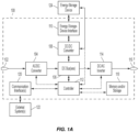
- FIG. 1A is a block diagram of a UPS 100 according to an example.
- FIG. 1A may illustrate a block diagram of one of several power modules of a UPS.
- the UPS 100 includes an input 102, an AC/DC converter 104, one or more DC busses 106, a DC/DC converter 108, an energy-storage-device interface 110, at least one controller 112, a DC/AC inverter 114, an output 116, a memory and/or storage 118, and one or more communication interfaces 120, which may be communicatively coupled to one or more external systems 122.
- the energy-storage device 124 is external to the UPS 100 and coupled to the UPS 100 via the energy-storage-device interface 110.
- the UPS 100 may include one or more energy-storage devices, which may include the energy-storage device 124.
- the energy-storage device 124 may include one or more batteries, capacitors, flywheels, or other energy-storage devices.
- the DC/AC inverter 114 is coupled to the one or more DC busses 106 and to the output 116, and is communicatively coupled to the controller 112.
- the output 116 is coupled to the DC/AC inverter 114, and to an external load (not pictured).
- the controller 112 is communicatively coupled to the AC/DC converter 104, the one or more DC busses 106, the DC/DC converter 108, the energy-storage-device interface 110, the DC/AC inverter 114, the memory and/or storage 118, and the communication interfaces 120.
- the energy-storage-device interface 110 receives the converted DC power, and provides the converted DC power to the energy-storage device 124 to charge the energy-storage device 124.
- the DC/AC inverter 114 receives DC power from the one or more DC busses 106, converts the DC power into regulated AC power, and provides the regulated AC power to the output 116 to be delivered to a load.
- controller 112 and the memory and/or storage 118 may be integrated together in a single component.
- the UPS 100 may be a multi-phase UPS, such as a three-phase UPS.
- the input 102 may include multiple inputs each configured to receive a respective phase line (and, in some examples, the multiple inputs may include a return input).
- FIG. 1A may be described with respect to a single connection and/or single-phase operation, it is to be appreciated that multi-phase operation is within the scope of FIG. 1A and the disclosure as a whole.
- the UPS may be subjected to a performance test in which it is operated to provide the specified magnitude of power or a magnitude of power above that which the facility may require in the event of mains failure.
- operational parameters of components of the UPS may be checked or, in some instances, continuously monitored to confirm that the components function properly when delivering the power.
- one or more components of the UPS may be checked or monitored to verify that the component does not heat to levels above specification during the performance test while the UPS is supplying the power.
- the test power may be provided as a series of high power step loads as illustrated in FIG. 6 .
- transient tests may be performed by measuring the change in the voltage at the output of the first UPS 100 at one or more of the times when the total power output changes (See FIG. 7 ) to determine if the voltage deviation is within specified limits or not.
- an amount of power lost as power circulates through the first UPS 100 and second UPS 240 is determined, for example, by monitoring a voltage or current at one or more points in the current circulation loop including the UPS 100 and second UPS 240.
- a control system of a UPS test system upon which the method is performed may provide an alert signal responsive to detection of an operational parameter of a component of the first UPS system 100 being outside of a predefined specification or responsive to failure of a component of the first UPS system 100 while the first UPS system 100 is maintaining the magnitude of the power delivered from the output of the first UPS system 100 to the inlet of the second UPS system 240.
- the control system may also provide an alert signal responsive to the first UPS system 100 being unable to maintain the magnitude of the power delivered from the output of the first UPS system 100 to the inlet of the second UPS system 240.
- control system of a UPS test system upon which the method is performed may terminate the method responsive to an operational parameter of a component of the first UPS system 100 or other system under test being outside of a predefined specification or responsive to failure of a component of the first UPS system 100 or other system under test in addition to or as an alternative to providing the alert signal.
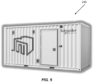
- the second UPS system 240 is housed in a portable container that is delivered to a location of the first UPS 100 prior to the method being performed and that is removed after the method is completed.
- this disclosure also contemplates a UPS, for example, a UPS 100 as illustrated in FIG. 1A with a controller 112 configured to perform embodiments of the method described above as well as a non-transitory computer readable media having instructions encoded therein which, when executed by a UPS or UPS test system, cause the UPS or UPS test system to perform embodiments of the method described above.
- a UPS for example, a UPS 100 as illustrated in FIG. 1A with a controller 112 configured to perform embodiments of the method described above as well as a non-transitory computer readable media having instructions encoded therein which, when executed by a UPS or UPS test system, cause the UPS or UPS test system to perform embodiments of the method described above.
Landscapes
- Physics & Mathematics (AREA)
- General Physics & Mathematics (AREA)
- Engineering & Computer Science (AREA)
- Power Engineering (AREA)
- Business, Economics & Management (AREA)
- Emergency Management (AREA)
- Stand-By Power Supply Arrangements (AREA)
Applications Claiming Priority (2)
| Application Number | Priority Date | Filing Date | Title |
|---|---|---|---|
| US202363612093P | 2023-12-19 | 2023-12-19 | |
| US18/980,073 US20250199085A1 (en) | 2023-12-19 | 2024-12-13 | Uninterruptible power supply for performing high power load testing |
Publications (2)
| Publication Number | Publication Date |
|---|---|
| EP4576494A2 true EP4576494A2 (de) | 2025-06-25 |
| EP4576494A3 EP4576494A3 (de) | 2025-08-06 |
Family
ID=93925602
Family Applications (1)
| Application Number | Title | Priority Date | Filing Date |
|---|---|---|---|
| EP24221133.2A Pending EP4576494A3 (de) | 2023-12-19 | 2024-12-18 | Verfahren und systeme zur durchführung einer hochleistungslastprüfung einer unterbrechungsfreien stromversorgung |
Country Status (2)
| Country | Link |
|---|---|
| US (1) | US20250199085A1 (de) |
| EP (1) | EP4576494A3 (de) |
Family Cites Families (4)
| Publication number | Priority date | Publication date | Assignee | Title |
|---|---|---|---|---|
| US20050286274A1 (en) * | 2004-06-29 | 2005-12-29 | Hans-Erik Pfitzer | Self-testing power supply apparatus, methods and computer program products |
| US8025437B2 (en) * | 2008-07-08 | 2011-09-27 | Eaton Corporation | Temperature monitoring in uninterruptible power supply systems using synthetic loading |
| US9239364B2 (en) * | 2012-12-18 | 2016-01-19 | Eaton Corporation | Methods of testing unInterruptible power supply (UPS) systems with multiple UPS modules |
| CN114665596A (zh) * | 2022-03-01 | 2022-06-24 | 广州科技贸易职业学院 | 一种ups电源的在线监控与预警系统 |
-
2024
- 2024-12-13 US US18/980,073 patent/US20250199085A1/en active Pending
- 2024-12-18 EP EP24221133.2A patent/EP4576494A3/de active Pending
Also Published As
| Publication number | Publication date |
|---|---|
| US20250199085A1 (en) | 2025-06-19 |
| EP4576494A3 (de) | 2025-08-06 |
Similar Documents
| Publication | Publication Date | Title |
|---|---|---|
| CA2653778C (en) | Data center uninterruptible power distribution architecture | |
| US10003200B2 (en) | Decentralized module-based DC data center | |
| US8648494B2 (en) | Uninterruptible power supply and method of energy saving thereof | |
| US20160285267A1 (en) | Power peak shaving system | |
| CN102460887B (zh) | 配电装置 | |
| US10375850B2 (en) | Rack power system and method | |
| CN116014706B (zh) | 供电方法、系统、电源设备和存储介质 | |
| CN102474129A (zh) | 备用电源与服务器系统中的主板的直接连结 | |
| CN108886254A (zh) | 一种多功能功率分配装置 | |
| US9032250B1 (en) | Online testing of secondary power unit | |
| US10082856B1 (en) | Performing a health check on power supply modules that operate in a current sharing mode | |
| US20140167504A1 (en) | Parallel boost voltage power supply with local energy storage | |
| US20120109555A1 (en) | Adaptive rating for backup power supply | |
| US20160079807A1 (en) | Uninterruptible power supply with inverter, charger, and active filter | |
| EP4576494A2 (de) | Verfahren und systeme zur durchführung einer hochleistungslastprüfung einer unterbrechungsfreien stromversorgung | |
| CN116868467A (zh) | 供电装置、设备、控制方法及存储介质 | |
| CN114094692B (zh) | 变电站设备的供电系统及方法 | |
| US12483062B2 (en) | Uninterruptible power supply, uninterruptible power supply control method, related apparatus, and system | |
| CN209895304U (zh) | 一种服务器供电系统及数据机房 | |
| US10998763B2 (en) | Power supply with programmable restriction | |
| CN118971320A (zh) | 一种供电柜供电方法、系统、存储介质及智能终端 | |
| CN119891504A (zh) | 基于并联直流电源的直流母线供电方法及电路 | |
| CN121417288A (zh) | 一种配电系统、方法、装置、电子设备及存储介质 | |
| CN121417289A (zh) | 一种配电系统、方法、装置、电子设备及存储介质 | |
| Cai et al. | Research on influence factor of system efficiency and power loss factor for DC power supply system of data center |
Legal Events
| Date | Code | Title | Description |
|---|---|---|---|
| PUAI | Public reference made under article 153(3) epc to a published international application that has entered the european phase |
Free format text: ORIGINAL CODE: 0009012 |
|
| STAA | Information on the status of an ep patent application or granted ep patent |
Free format text: STATUS: THE APPLICATION HAS BEEN PUBLISHED |
|
| AK | Designated contracting states |
Kind code of ref document: A2 Designated state(s): AL AT BE BG CH CY CZ DE DK EE ES FI FR GB GR HR HU IE IS IT LI LT LU LV MC ME MK MT NL NO PL PT RO RS SE SI SK SM TR |
|
| PUAL | Search report despatched |
Free format text: ORIGINAL CODE: 0009013 |
|
| AK | Designated contracting states |
Kind code of ref document: A3 Designated state(s): AL AT BE BG CH CY CZ DE DK EE ES FI FR GB GR HR HU IE IS IT LI LT LU LV MC ME MK MT NL NO PL PT RO RS SE SI SK SM TR |
|
| RIC1 | Information provided on ipc code assigned before grant |
Ipc: H02J 9/06 20060101AFI20250701BHEP Ipc: G01R 31/42 20060101ALI20250701BHEP Ipc: G01R 31/40 20200101ALI20250701BHEP |
|
| STAA | Information on the status of an ep patent application or granted ep patent |
Free format text: STATUS: REQUEST FOR EXAMINATION WAS MADE |