EP4576442A1 - Electrical contact for a male electrical connector - Google Patents
Electrical contact for a male electrical connector Download PDFInfo
- Publication number
- EP4576442A1 EP4576442A1 EP24221089.6A EP24221089A EP4576442A1 EP 4576442 A1 EP4576442 A1 EP 4576442A1 EP 24221089 A EP24221089 A EP 24221089A EP 4576442 A1 EP4576442 A1 EP 4576442A1
- Authority
- EP
- European Patent Office
- Prior art keywords
- pin
- electrical contact
- ring
- indentation
- electrical
- Prior art date
- Legal status (The legal status is an assumption and is not a legal conclusion. Google has not performed a legal analysis and makes no representation as to the accuracy of the status listed.)
- Pending
Links
Images



Classifications
-
- H—ELECTRICITY
- H01—ELECTRIC ELEMENTS
- H01R—ELECTRICALLY-CONDUCTIVE CONNECTIONS; STRUCTURAL ASSOCIATIONS OF A PLURALITY OF MUTUALLY-INSULATED ELECTRICAL CONNECTING ELEMENTS; COUPLING DEVICES; CURRENT COLLECTORS
- H01R13/00—Details of coupling devices of the kinds covered by groups H01R12/70 or H01R24/00 - H01R33/00
- H01R13/02—Contact members
- H01R13/04—Pins or blades for co-operation with sockets
-
- H—ELECTRICITY
- H01—ELECTRIC ELEMENTS
- H01R—ELECTRICALLY-CONDUCTIVE CONNECTIONS; STRUCTURAL ASSOCIATIONS OF A PLURALITY OF MUTUALLY-INSULATED ELECTRICAL CONNECTING ELEMENTS; COUPLING DEVICES; CURRENT COLLECTORS
- H01R13/00—Details of coupling devices of the kinds covered by groups H01R12/70 or H01R24/00 - H01R33/00
- H01R13/40—Securing contact members in or to a base or case; Insulating of contact members
- H01R13/42—Securing in a demountable manner
- H01R13/422—Securing in resilient one-piece base or case, e.g. by friction; One-piece base or case formed with resilient locking means
-
- H—ELECTRICITY
- H01—ELECTRIC ELEMENTS
- H01R—ELECTRICALLY-CONDUCTIVE CONNECTIONS; STRUCTURAL ASSOCIATIONS OF A PLURALITY OF MUTUALLY-INSULATED ELECTRICAL CONNECTING ELEMENTS; COUPLING DEVICES; CURRENT COLLECTORS
- H01R13/00—Details of coupling devices of the kinds covered by groups H01R12/70 or H01R24/00 - H01R33/00
- H01R13/46—Bases; Cases
- H01R13/52—Dustproof, splashproof, drip-proof, waterproof, or flameproof cases
- H01R13/521—Sealing between contact members and housing, e.g. sealing insert
-
- H—ELECTRICITY
- H01—ELECTRIC ELEMENTS
- H01R—ELECTRICALLY-CONDUCTIVE CONNECTIONS; STRUCTURAL ASSOCIATIONS OF A PLURALITY OF MUTUALLY-INSULATED ELECTRICAL CONNECTING ELEMENTS; COUPLING DEVICES; CURRENT COLLECTORS
- H01R13/00—Details of coupling devices of the kinds covered by groups H01R12/70 or H01R24/00 - H01R33/00
- H01R13/40—Securing contact members in or to a base or case; Insulating of contact members
- H01R13/42—Securing in a demountable manner
- H01R13/428—Securing in a demountable manner by resilient locking means on the contact members; by locking means on resilient contact members
- H01R13/432—Securing in a demountable manner by resilient locking means on the contact members; by locking means on resilient contact members by stamped-out resilient tongue snapping behind shoulder in base or case
-
- H—ELECTRICITY
- H01—ELECTRIC ELEMENTS
- H01R—ELECTRICALLY-CONDUCTIVE CONNECTIONS; STRUCTURAL ASSOCIATIONS OF A PLURALITY OF MUTUALLY-INSULATED ELECTRICAL CONNECTING ELEMENTS; COUPLING DEVICES; CURRENT COLLECTORS
- H01R13/00—Details of coupling devices of the kinds covered by groups H01R12/70 or H01R24/00 - H01R33/00
- H01R13/46—Bases; Cases
- H01R13/502—Bases; Cases composed of different pieces
- H01R13/506—Bases; Cases composed of different pieces assembled by snap action of the parts
Definitions
- the present invention relates to an electrical contact for a male electrical connector.
- the invention also relates to an electrical contact pin, a connector housing, and a male electrical connector.
- an electrical contact pin comprises a first part configured to establish an electrical contact and disposed at a first end of the pin, and a second part configured to connect the pin to an electrical conductor and disposed at a second end of the pin.
- the first part can have, in a plane orthogonal to the elongation direction of the pin, a rectangular section.
- the present invention aims to propose an improved solution for sealing a male electrical connector with an electrical contact pin of rectangular cross-section.
- the aim of the invention is achieved by means of an electrical contact for a male electrical connector according to the present invention.
- the electrical contact according to the invention comprises an electrical contact pin and an O-ring.
- the pin comprises a first part configured to establish an electrical contact with a homologous electrical terminal, the first part being disposed at a first end of the pin and having, in a plane orthogonal to the elongation direction of the pin, a rectangular cross-section.
- the pin also comprises a second part configured to connect the pin to an electrical conductor, the second part being disposed at a second end of the pin opposite the first end.
- the pin moreover comprises, between the first part and the second part, a narrowed part adapted to house an O-ring.
- the O-ring is arranged at the pin, so as to be housed in the narrowed part.
- the electrical contact pin By configuring the electrical contact pin with a narrowed part adapted to house an O-ring, the electrical contact pin can be provided with an O-ring, despite the rectangular section of its first part.
- the risks linked to the installation of the O-ring on the rectangular section of the first part in particular the risk of damage to the O-ring by a ridge of the pin with a rectangular section, and the risk of loss of sealing at the side faces of the pin with a rectangular section, are reduced or even removed.
- the present invention therefore offers a sealing solution for a pin with a rectangular section which is less expensive with respect to those known from the prior art, without risking degradation in terms of durability or loss in sealing performance. On the contrary, the present invention can even enable an increase of sealing performance compared to the more expensive solutions of the prior art.
- the narrowed part can have, in a plane orthogonal to the elongation direction of the pin, a rounded section having a shape configured to be fitted by an O-ring. In this configuration, the narrowed part is even better adapted to sealingly house the O-ring.
- the narrowed part can have an oval section or an elliptical section or a section having two parallel sides, which connect between them two arcs arranged at opposite ends of the parallel sides.
- the arcs can be two circular arcs, for example, semi-circles.
- the narrowed part can have a section having four two-by-two parallel sides, which connect between them four arcs, in particular four quarter-circle arcs, arranged at the intersections of the four two-by-two parallel sides.
- the O-ring housed in the narrowed part can thus even better fit the shape of the section of the narrowed part and improve the sealing of the housing of the O-ring in the narrowed part.
- the pin can comprise, in a first side of the pin corresponding to a first extension of the rectangular section of the first part, a first indentation, and, in a second side of the pin opposite the first side, a second indentation opposite the first indentation, the first and second indentations together forming the narrowed part.
- the first extension of the rectangular section can correspond to a thickness of the first part of the electrical contact pin.
- the first indentation and/or the second indentation can have a depth of between 100% and 300%, preferably between 150% and 250%, of the first extension of the rectangular section of the first part. With indentations of this depth, the housing of the O-ring can be sufficiently reliable, to not to risk its movement along the elongation direction of the pin, without compromising the structural integrity of the pin and/or the elasticity of the O-ring.
- the first indentation and/or the second indentation can have a depth of between 10% and 40%, preferably between 20% and 30%, of a second extension, preferably orthogonal to the first extension, of the rectangular section of the first part.
- the second extension of the rectangular section can correspond to a width of the first part of the electrical contact pin.
- the first extension i.e. the thickness
- the housing of the O-ring can be more reliable without compromising the integrity of the electrical contact.
- the edges of the first indentation and/or of the second indentation can be rounded, in particular rounded along an oval or elliptical or circular arc.
- the present invention also relates to an electrical contact pin for an electrical contact according to one of the aspects described above.
- the pin comprises a first part configured to establish an electrical contact with a homologous electrical terminal, the first part being disposed at a first end of the pin and having, in a plane orthogonal to the elongation direction of the pin, a rectangular section, a second part configured for connecting the pin to an electrical conductor, the second part being disposed at a second end of the pin opposite the first end, and, between the first part and the second part, a narrowed part adapted to house an O-ring.
- This pin can be implemented in an electrical contact according to one of the aspects described above, and thus benefit from the respective advantages of the aspects of the electrical contact.
- the invention further comprises a connector housing for a male electrical connector, the housing forming a cavity configured to house an electrical contact according to one of the aspects described above, and having a first face comprising an opening leading to the cavity, the opening having a rectangular section configured to receive the electrical contact pin of the electrical contact.
- the connector housing comprises a projecting part extending along a perimeter of the opening and having a shape configured to be fitted by an O-ring housed in the narrowed part of the pin, so as to form a sealing seat. Thanks to the projecting part and the sealing seat, the positioning of the O-ring housed in the narrowed part can be additionally secured.
- the aim of the invention is moreover achieved by means of a male electrical connector, comprising such a housing, and an electrical contact according to one of the aspects described above, the pin being housed in the cavity, such that the second part is arranged inside the housing and the first part is arranged outside the housing, and the O-ring being housed in the sealing seat of the housing, so as to fit the shape of the projecting part extending along a perimeter of the opening.
- the installation of the electrical contact pin in the connector housing can be sealed in a quicker and less expensive way, with respect to the solutions of the prior art, without losing sealing performance.
- the male electrical connector can comprise a retaining element enveloping the electrical contact pin and fixed to the projecting part, so as to close the inner space formed by the projecting part. This can further secure and seal the installation of the electrical contact in the connector housing.
- the retaining element can be fixed at an outer surface of the projecting part, in particular by a form-fitting means. This makes it possible to manually lock the electrical contact by means of the retaining element and in particular, to visually verify the locking state.
- Figure 1 shows an exploded view of a male electrical connector according to the invention.
- Figure 2 shows a perspective view and a close-up view of an electrical contact pin for the connector of figure 1 .
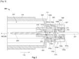
- Figure 3 shows a cross-sectional view of the electrical connector of figure 1 in an assembled state.
- Figure 4 shows a cross-sectional view of part of the electrical connector of figure 1 in an assembled state.
- FIG. 1 shows an exploded view of a male electrical connector according to a first embodiment of the invention.
- the electrical connector 100 is a power connector for a vehicle application, in particular in the field of the electric motor vehicles.
- the electrical connector 100 comprises a connector housing 101, two identical electrical contacts 103a, 103b, and two identical retaining elements 105a, 105b.
- the two electrical contacts 103a, 103b are mutually identical, and the two retaining elements 105a, 105b are also mutually identical. Only one single electrical contact 103a, as well as one single retaining element 105a will therefore be described below.
- Each electrical contact 103a, 103b comprises an electrical contact pin 107a, 107b and an O-ring 109a, 109b.
- the connector housing 101, the electrical contacts 103a, 103b and the electrical contact pins 107a, 107b are described below as parts of the electrical connector 100 according to the first embodiment of the invention. It must however be noted that the connector housing 101 is also a connector housing for a male electrical connector according to a second embodiment of the invention, and each electrical contact 103a, 103b is also an electrical contact for a male electrical connector according to a third embodiment of the invention. Likewise, each electrical contact pin 107a, 107b is also an electrical contact pin in according to a fourth embodiment of the invention.
- the connector housing 101 is made of elastomer so as to form, for each electrical contact 103a, 103b, a cavity configured to house said respective electrical contact 103a, 103b, such as illustrated, in particular, in figure 3 .
- the housing 101 has a first outer face 111 comprising, for each electrical contact 103a, 103b, an opening leading to a respective one of said cavities, such as illustrated in figure 3 .
- the housing 101 comprises, for each electrical contact 103a, 103b, a projecting part 113a, 113b projecting from the first face 111 to the outside of the housing 101, in a direction 115 of connection of the connector 100.
- Each projecting part 113a, 113b extends along a perimeter 117a, 117b of a respective one of said openings, thus forming a closed border around each of the openings.
- Each of the projecting parts 113a, 113b comprises a plurality of, in this case two, fixing elements for fixing a retaining element, such as one of the retaining elements 105a, 105b.
- the fixing elements are projections 119a, 119b formed on an outer surface 121a, 121b of a respective projecting part 113a, 113b.
- the projections 119a, 119b are configured as form-fitting means for fixing a retaining element 105a, 105b on the respective projecting part 113a, 113b.
- each projection 119a, 119b is configured to elastically deflect a respective leg 123a, 123b, 123c, 123d of a retaining element 105a, 105b during the installation of said retaining element 105a, 105b until a housing of a hook 125a, 125b of the leg 123a, 123b behind the projection 119a, 119b creates a positive engagement.
- This positive engagement will be described further in reference to figure 3 .
- the pin 107a is a metal part, preferably of a copper alloy, extending along an elongation direction 200.
- the pin 107a comprises, in the elongation direction 200, a first part 201, a narrowed part 203, and a second part 205.
- the narrowed part 203 is arranged, i.e. interposed, between the first part 201 and the second part 203, and adapted to house an O-ring 109a, 109b.
- the first part 201 is disposed at a first end 207 of the pin 107a and the second part is disposed at a second end 209 of the pin 107a, the second end 209 being opposite the first end 207.
- the electrical contact pin 107a is a tab-type pin stamped from a metal sheet, in this case copper alloy. Alternatively, the pin 107a can also be manufactured by milling.
- the first part 201 of the pin 107a has, in a plane orthogonal to the elongation direction 200, a rectangular section. Said rectangular section has a first extension 211 and a second extension 213 orthogonal to the first extension.
- the first extension 211 corresponds to the thickness of the pin 107a at the first part 201, and in particular, to the thickness of the metal sheet used.
- the second extension 213 corresponds to the pin width 107a at the first part 201. In this embodiment, the second extension 213 is at least 6 times, preferably between 7 and 10 times, larger than the first extension corresponding to the thickness 211 of the pin 107a.
- the thickness of the pin 107a is substantially uniform along the elongation direction 200.
- the width of the pin 107a is not uniform, and in particular, the second extension 213, i.e. the width of the pin 107a at the first part 201, is greater by 3% to 10% than the width of the pin 215 at the second part 205.
- the first part 201 is configured to establish an electrical contact with a homologous electrical terminal when the male electrical connector 100 is connected with a homologous female electrical connector.
- the second part 205 is configured for connecting the pin 107a to an electrical conductor, in particular for crimping or welding with a conductive core of a cable.
- the second part 205 moreover comprises a central rectangular perforation 217. A portion of the second part 205 adjacent the central rectangular perforation 217 is partially cut and deflected with respect to the rest of the second part 205 in order to create a locking tab 219 for locking the pin 107a in the housing 101. The locking of the pin 107a by means of the locking tab 219 will be described further in reference to figure 3 .
- a first indentation 221 is formed, between the first part 201 and the second part 205, in a first lateral side 223 of the pin 107a, between the first part 201 and the second part 205.
- a second indentation 225 is formed opposite the first indentation 221, also between the first part 201 and the second part 205, in a second lateral side 227 of the pin 107a opposite the first lateral side 223.
- the first and second lateral sides 221, 223 correspond to lateral sides of thickness, i.e. of first extension 211, of the pin 107a.
- the first indentation 221 and the second indentation 223 form the narrowed part 203.
- the narrowed part 203 has a thickness corresponding to the first extension 211 and a width 229 less than the width 213 of the first part 201 and the width 215 of the second part 205.
- Figure comprises a close-up view of the pin 107a at the first indentation 221, which illustrates that edges 231 of the indentation 221 extending in a direction parallel to the elongation direction 200 are rounded, and that edges 233, 235 of the indentation 221 extending in a direction orthogonal to the elongation direction 200 are also rounded.
- an O-ring such as the seals 109a, 109b, can be housed in the narrowed part 203, so as to fit the shape of the rounded section of the narrowed part 203.
- the rounded shape of the section of the narrowed part 203 in width 229 is configured to be fitted by an O-ring 109a, 109b.
- edges 231, 233, 235 are, in this case, rounded elliptically. In variants, the edges 231, 233, 235 can also be rounded ovally or circularly. The rounding of the edges 231, 233, 235 therefore corresponds to a separate or additional step to an optional chamfering of the ridges of the pin 107a, such as illustrated in figure 2 by means of chamfers 237.
- the indentations 221, 225 have a depth 237, in a direction orthogonal to the elongation direction 200, of between 10% and 40%, preferably between 20% and 30%, of the second extension 213 of the first part 201.
- the depth 237 of the indentations 221, 225 is moreover between 100% and 300%, preferably between 150% and 250%, of the thickness, i.e. of the first extension 211, of the first part 201.
- Figure 3 shows a cross-sectional view of the male electrical connector 100 in an assembled state, along the cross-sectional line 127 indicated in figure 1 .
- the electrical contact 103a is installed in the connector housing 101.
- the electrical contact pin 107a is housed in a cavity 301 and configured to receive the pin 107a, such that the second part 205 is arranged inside the cavity 301, and the first part 201 is arranged outside the cavity 301 and the housing 101.
- the pin 107a is inserted, along an insertion direction 300 parallel to the elongation direction 200 and opposite the connection direction 115, into the cavity 301 through an opening 303 in the first face 111 of the housing 107.
- the opening 303 has a rectangular section having substantially the dimensions of the second part 205 of the pin 107a, in particular the thickness 211 and the width 215.
- the locking tab 219 is elastically deflected until it has exceeded the opening 303, then returning to its transverse rest state and thus positively engaging an inner edge 305 of the housing 101.
- the projecting part 113a extending along the perimeter 117a of the opening 303, is formed such that an outer surface 121a of the projecting part 113 comprises the projections 119a, 119c. Moreover, the projecting part 113a is formed such that an inner surface 307 of the projecting part 113a defines an inner open space 309.
- the space 309 is a sealing seat for the O-ring 109a, such as described below in reference to figure 4 .
- FIG. 3 shows the electrical contact 103a in an assembled state, in which the electrical contact pin 107a is provided with an O-ring 109a.
- the O-ring 109a is housed in the narrowed part 203 of the pin 107a.
- the O-ring 109a is elastically extended and slipped over the first part 201 until said O-ring 109a returns to a more contracted rest state at the indentations 221, 225.
- the O-ring 109a is a rubber O-ring, for example of the vinyl-methyl-siloxane (VMQ) type or ethylenepropylene-diene monomer (EPDM) type.
- VMQ vinyl-methyl-siloxane
- EPDM ethylenepropylene-diene monomer
- the connector 100 such as illustrated in figure 3 in its assembled state, comprises the retaining element 105a, comprises a central part 311, from which the legs 123b, 123d extend. Each leg 123b, 123d comprises a hook 125b, 125d arranged at a respective end of the legs 123b, 123d.
- the central part 311 comprises a through slot 313 having substantially the dimensions of the rectangular section of the first part 201 of the electrical contact pin 107a, in particular the thickness 211 and the width 213.
- the retaining element 105a is configured to be slipped over the first part 201 of the pin 107a, through the through slot 313 going through the central part 311.
- the legs 123b, 123d can be moved closer to the projecting part 113a and elastically deflected over the projections 119a, 119c, in order to create a positive engagement between the projections 119a, 119c and the hooks 125b, 125d, once the projections 119a, 119c have been exceeded.
- the hooks 125b, 125d and the projections 119a, 119c are complementary elements of a form-fitting means to fix the retaining element 105a at the connector housing 101.
- the retaining element 105a envelops the pin 107a and in particular, the narrowed part 203 of the pin 107, and is fixed to the projecting part 113a.
- the central part 311 closes, in particular blocks, the open inner space 309 of the sealing seat, thus increasing the sealing of the installation of the electrical contact 103 and securing the contact 103a.
- Figure 4 shows a cross-sectional view of the male electrical connector 100 along the cross-sectional line 315 of figure 3 . Specifically, figure 4 shows a cross-section of the connector 100, in an assembled state, at its projecting part 113a. Thus, a section of the O-ring 109a and a section 400 of the pin 107a are illustrated.
- the section 400 of the pin 107a is a section in a plane orthogonal to the elongation direction 200 of the pin 107a.
- the narrowed part 203 is machined so as to have a rounded section 400.
- the rounded section 400 is, in the present embodiment, a section being stadium-shaped, i.e. a section 400 having two parallel sides 401a, 401b which connect between them two elliptical arcs 403a, 403b arranged at the opposite ends of the parallel sides 401a, 401b.
- the arc 403b corresponds to the edge 231 of figure 2 .
- the section 400 can also have four two-by-two parallel sides, which connect between them four quarter-circular arcs, arranged at the intersections of the four two-by-two parallel sides.
- the narrowed part 203 is particularly adapted for housing the O-ring 109a.
- the section 400 has a shape configured to be fitted by the O-ring 109.
- the pin 107a is provided with the O-ring 109a housed in the narrowed part 203, the O-ring 109a fitting the section 400, i.e. the contour, of the narrowed part 203.
- the O-ring 109a can seal the insertion of the pin 107a into the opening 303a, without losing sealing performance or durability due to the rectangular section of the first part 201 of the pin 107a.
- the radial sealing performance and cost efficiency of the O-ring is adapted for a male electrical connector with pins of rectangular cross-section.
- the present invention offers an improved solution for sealing the installation of pins with a rectangular section in an electrical connector housing.
- sealing performance up to IP54 can be achieved by means of a conventional O-ring.
- the inner surface 307 of the projecting part 113a which produces the open inner space 309 has a shape which is configured to be fitted by the O-ring 109a.
- the open inner space 309 has a section being stadium-shaped corresponding to the shape and thickness 405 of the seal 109a when housed in the narrowed part 203.
- the projecting part 113a is moulded to envelop the O-ring 109a such that the O-ring 109a sealingly fits the inner surface 307.
- the O-ring 109a is housed in the sealing seat 309 of the housing 101, so as to fit the shape of the projection 113a.
- the sealing performance of the connector 100 is thus improved, and the O-ring 109a is protected from environmental externalities.
- the male electrical connector of the invention can comprise only one single electrical contact.
- the male electrical connector can comprise a plurality, for example 3, 6 or 8, of electrical contacts.
- the electrical connector cannot comprise retaining elements such as the retaining elements 105a, 105b.
- a locking means for the contact pins 107a, 107b different from, or additional to, the present locking tab system 219 can be considered.
Landscapes
- Connector Housings Or Holding Contact Members (AREA)
Abstract
The invention relates to an electrical contact for a male electrical connector (100), the electrical contact (103a, 103b) comprising an electrical contact pin (107a, 107b) and an O-ring (109a, 109b), the pin (107a, 107b) comprising a first part (201), a second part (205), and, between the first part (201) and the second part (205), a narrowed part (203) adapted to house an O-ring (109a, 109b), the O-ring (109a, 109b) being arranged at the pin (107a, 107b), so as to be housed in the narrowed part (203). The invention also relates to an electrical contact pin (107a, 107b), a connector housing (101), and a male electrical connector (100).
Description
- . The present invention relates to an electrical contact for a male electrical connector. The invention also relates to an electrical contact pin, a connector housing, and a male electrical connector.
- . In the field of electrical connectivity, it is known to provide an electrical connector, called a male electrical connector, comprising at least one electrical contact pin, and a homologous electrical connector, called a female electrical connector, comprising at least one homologous electrical terminal, for example an electrical contact terminal. Generally, an electrical contact pin comprises a first part configured to establish an electrical contact and disposed at a first end of the pin, and a second part configured to connect the pin to an electrical conductor and disposed at a second end of the pin. Typically, the first part can have, in a plane orthogonal to the elongation direction of the pin, a rectangular section.
- . In order to seal the arrangement of an electrical contact pin in a housing of the male electrical connector, certain solutions provide for providing the electrical contact pin with a rectangular seal, the rectangular seal being moulded to have a specific shape homologated to the corresponding rectangular section of the first part. Thus, each type of rectangular section requires a corresponding rectangular seal. Other even more expensive solutions provide for a potting of the pin installed in its male electrical connector housing.
- . Given the above, the present invention aims to propose an improved solution for sealing a male electrical connector with an electrical contact pin of rectangular cross-section.
- . The aim of the invention is achieved by means of an electrical contact for a male electrical connector according to the present invention. The electrical contact according to the invention comprises an electrical contact pin and an O-ring. The pin comprises a first part configured to establish an electrical contact with a homologous electrical terminal, the first part being disposed at a first end of the pin and having, in a plane orthogonal to the elongation direction of the pin, a rectangular cross-section. The pin also comprises a second part configured to connect the pin to an electrical conductor, the second part being disposed at a second end of the pin opposite the first end. The pin moreover comprises, between the first part and the second part, a narrowed part adapted to house an O-ring. The O-ring is arranged at the pin, so as to be housed in the narrowed part.
- . By configuring the electrical contact pin with a narrowed part adapted to house an O-ring, the electrical contact pin can be provided with an O-ring, despite the rectangular section of its first part. Thus, the risks linked to the installation of the O-ring on the rectangular section of the first part, in particular the risk of damage to the O-ring by a ridge of the pin with a rectangular section, and the risk of loss of sealing at the side faces of the pin with a rectangular section, are reduced or even removed.
- . The present invention therefore offers a sealing solution for a pin with a rectangular section which is less expensive with respect to those known from the prior art, without risking degradation in terms of durability or loss in sealing performance. On the contrary, the present invention can even enable an increase of sealing performance compared to the more expensive solutions of the prior art.
- . According to an aspect of the invention, the narrowed part can have, in a plane orthogonal to the elongation direction of the pin, a rounded section having a shape configured to be fitted by an O-ring. In this configuration, the narrowed part is even better adapted to sealingly house the O-ring.
- . According to an aspect of the invention, the narrowed part can have an oval section or an elliptical section or a section having two parallel sides, which connect between them two arcs arranged at opposite ends of the parallel sides. In particular, the arcs can be two circular arcs, for example, semi-circles. According to another aspect of the invention, the narrowed part can have a section having four two-by-two parallel sides, which connect between them four arcs, in particular four quarter-circle arcs, arranged at the intersections of the four two-by-two parallel sides. The O-ring housed in the narrowed part can thus even better fit the shape of the section of the narrowed part and improve the sealing of the housing of the O-ring in the narrowed part.
- . According to an aspect of the invention, the pin can comprise, in a first side of the pin corresponding to a first extension of the rectangular section of the first part, a first indentation, and, in a second side of the pin opposite the first side, a second indentation opposite the first indentation, the first and second indentations together forming the narrowed part. The first extension of the rectangular section can correspond to a thickness of the first part of the electrical contact pin. By forming two opposite indentations, a narrowed part can be obtained, which can house the O-ring more reliably than, for example, with one single indentation. In particular, in this configuration, a movement of the O-ring along the elongation direction of the pin can be blocked.
- . According to an aspect of the invention, the first indentation and/or the second indentation can have a depth of between 100% and 300%, preferably between 150% and 250%, of the first extension of the rectangular section of the first part. With indentations of this depth, the housing of the O-ring can be sufficiently reliable, to not to risk its movement along the elongation direction of the pin, without compromising the structural integrity of the pin and/or the elasticity of the O-ring.
- . According to an aspect of the invention, the first indentation and/or the second indentation can have a depth of between 10% and 40%, preferably between 20% and 30%, of a second extension, preferably orthogonal to the first extension, of the rectangular section of the first part. The second extension of the rectangular section can correspond to a width of the first part of the electrical contact pin. For example, when the electrical contact pin is of the tab type, the first extension, i.e. the thickness, can be less, in particular more than 80% less than a second extension orthogonal to the first extension, i.e. the width. Also, in this configuration, the housing of the O-ring can be more reliable without compromising the integrity of the electrical contact.
- . According to an aspect of the invention, the edges of the first indentation and/or of the second indentation can be rounded, in particular rounded along an oval or elliptical or circular arc. Thus, the risk of weakening of the O-ring can be reduced when it is installed on the pin, in order to be housed in the narrowed part.
- . The present invention also relates to an electrical contact pin for an electrical contact according to one of the aspects described above. The pin comprises a first part configured to establish an electrical contact with a homologous electrical terminal, the first part being disposed at a first end of the pin and having, in a plane orthogonal to the elongation direction of the pin, a rectangular section, a second part configured for connecting the pin to an electrical conductor, the second part being disposed at a second end of the pin opposite the first end, and, between the first part and the second part, a narrowed part adapted to house an O-ring. This pin can be implemented in an electrical contact according to one of the aspects described above, and thus benefit from the respective advantages of the aspects of the electrical contact.
- . The invention further comprises a connector housing for a male electrical connector, the housing forming a cavity configured to house an electrical contact according to one of the aspects described above, and having a first face comprising an opening leading to the cavity, the opening having a rectangular section configured to receive the electrical contact pin of the electrical contact. The connector housing comprises a projecting part extending along a perimeter of the opening and having a shape configured to be fitted by an O-ring housed in the narrowed part of the pin, so as to form a sealing seat. Thanks to the projecting part and the sealing seat, the positioning of the O-ring housed in the narrowed part can be additionally secured.
- . The aim of the invention is moreover achieved by means of a male electrical connector, comprising such a housing, and an electrical contact according to one of the aspects described above, the pin being housed in the cavity, such that the second part is arranged inside the housing and the first part is arranged outside the housing, and the O-ring being housed in the sealing seat of the housing, so as to fit the shape of the projecting part extending along a perimeter of the opening.
- . Thus, the installation of the electrical contact pin in the connector housing can be sealed in a quicker and less expensive way, with respect to the solutions of the prior art, without losing sealing performance.
- . According to an aspect of the invention, the male electrical connector can comprise a retaining element enveloping the electrical contact pin and fixed to the projecting part, so as to close the inner space formed by the projecting part. This can further secure and seal the installation of the electrical contact in the connector housing.
- . According to an aspect of the invention, the retaining element can be fixed at an outer surface of the projecting part, in particular by a form-fitting means. This makes it possible to manually lock the electrical contact by means of the retaining element and in particular, to visually verify the locking state.
- . The aims, features and advantages of the invention such as outlined above will be more exhaustively understood and assessed by studying the following, more detailed description of preferred embodiments of the invention, using the accompanying drawings.
- .
Figure 1 shows an exploded view of a male electrical connector according to the invention. - .
Figure 2 shows a perspective view and a close-up view of an electrical contact pin for the connector offigure 1 . - .
Figure 3 shows a cross-sectional view of the electrical connector offigure 1 in an assembled state. - .
Figure 4 shows a cross-sectional view of part of the electrical connector offigure 1 in an assembled state. - . The technical features and associated advantages of the embodiments described below can be freely combined one by one, or adapted to particular embodiments, insofar as the spirit of the invention such as described above is respected.
- . Below, identical references in the figures and the description are used to reference elements of the same nature. Unless otherwise explained in the text, the objects illustrated in the figures are neither to scale with respect to one another, nor to scale in their Cartesian dimensions with respect to one another.
- .
Figure 1 shows an exploded view of a male electrical connector according to a first embodiment of the invention. According to this first embodiment, theelectrical connector 100 is a power connector for a vehicle application, in particular in the field of the electric motor vehicles. Theelectrical connector 100 comprises aconnector housing 101, two identicalelectrical contacts 103a, 103b, and twoidentical retaining elements electrical contacts 103a, 103b are mutually identical, and the two retainingelements electrical contact 103a, as well as onesingle retaining element 105a will therefore be described below. Eachelectrical contact 103a, 103b comprises anelectrical contact pin ring - . The
connector housing 101, theelectrical contacts 103a, 103b and theelectrical contact pins electrical connector 100 according to the first embodiment of the invention. It must however be noted that theconnector housing 101 is also a connector housing for a male electrical connector according to a second embodiment of the invention, and eachelectrical contact 103a, 103b is also an electrical contact for a male electrical connector according to a third embodiment of the invention. Likewise, eachelectrical contact pin - . The
connector housing 101 is made of elastomer so as to form, for eachelectrical contact 103a, 103b, a cavity configured to house said respectiveelectrical contact 103a, 103b, such as illustrated, in particular, infigure 3 . Thehousing 101 has a firstouter face 111 comprising, for eachelectrical contact 103a, 103b, an opening leading to a respective one of said cavities, such as illustrated infigure 3 . Thehousing 101 comprises, for eachelectrical contact 103a, 103b, a projectingpart first face 111 to the outside of thehousing 101, in adirection 115 of connection of theconnector 100. Each projectingpart perimeter - . Each of the projecting
parts elements projections outer surface part projections element part projection respective leg element element hook 125a, 125b of theleg projection figure 3 . - . An
electrical contact pin 107a for theconnector 100 is now described in reference tofigure 2 . Thepin 107a is a metal part, preferably of a copper alloy, extending along anelongation direction 200. Thepin 107a comprises, in theelongation direction 200, afirst part 201, anarrowed part 203, and asecond part 205. Thenarrowed part 203 is arranged, i.e. interposed, between thefirst part 201 and thesecond part 203, and adapted to house an O-ring first part 201 is disposed at afirst end 207 of thepin 107a and the second part is disposed at asecond end 209 of thepin 107a, thesecond end 209 being opposite thefirst end 207. - . The
electrical contact pin 107a is a tab-type pin stamped from a metal sheet, in this case copper alloy. Alternatively, thepin 107a can also be manufactured by milling. Thefirst part 201 of thepin 107a has, in a plane orthogonal to theelongation direction 200, a rectangular section. Said rectangular section has afirst extension 211 and asecond extension 213 orthogonal to the first extension. Thefirst extension 211 corresponds to the thickness of thepin 107a at thefirst part 201, and in particular, to the thickness of the metal sheet used. Thesecond extension 213 corresponds to thepin width 107a at thefirst part 201. In this embodiment, thesecond extension 213 is at least 6 times, preferably between 7 and 10 times, larger than the first extension corresponding to thethickness 211 of thepin 107a. - . In this embodiment, the thickness of the
pin 107a is substantially uniform along theelongation direction 200. The width of thepin 107a is not uniform, and in particular, thesecond extension 213, i.e. the width of thepin 107a at thefirst part 201, is greater by 3% to 10% than the width of thepin 215 at thesecond part 205. - . The
first part 201 is configured to establish an electrical contact with a homologous electrical terminal when the maleelectrical connector 100 is connected with a homologous female electrical connector. Thesecond part 205 is configured for connecting thepin 107a to an electrical conductor, in particular for crimping or welding with a conductive core of a cable. - . The
second part 205 moreover comprises a centralrectangular perforation 217. A portion of thesecond part 205 adjacent the centralrectangular perforation 217 is partially cut and deflected with respect to the rest of thesecond part 205 in order to create alocking tab 219 for locking thepin 107a in thehousing 101. The locking of thepin 107a by means of thelocking tab 219 will be described further in reference tofigure 3 . - . A
first indentation 221 is formed, between thefirst part 201 and thesecond part 205, in a firstlateral side 223 of thepin 107a, between thefirst part 201 and thesecond part 205. Asecond indentation 225 is formed opposite thefirst indentation 221, also between thefirst part 201 and thesecond part 205, in a secondlateral side 227 of thepin 107a opposite the firstlateral side 223. The first and secondlateral sides first extension 211, of thepin 107a. Together, thefirst indentation 221 and thesecond indentation 223 form thenarrowed part 203. Thus, thenarrowed part 203 has a thickness corresponding to thefirst extension 211 and awidth 229 less than thewidth 213 of thefirst part 201 and thewidth 215 of thesecond part 205. - . The edges of the
indentations narrowed part 203 has a section inwidth 229, i.e. in a plane orthogonal to theelongation direction 200, which is rounded. The shape of the rounded section will be described further in reference tofigure 4 . Figure comprises a close-up view of thepin 107a at thefirst indentation 221, which illustrates thatedges 231 of theindentation 221 extending in a direction parallel to theelongation direction 200 are rounded, and that edges 233, 235 of theindentation 221 extending in a direction orthogonal to theelongation direction 200 are also rounded. Thanks to therounded edges 231 of thenarrowed part 203, an O-ring, such as theseals narrowed part 203, so as to fit the shape of the rounded section of thenarrowed part 203. I.e. the rounded shape of the section of thenarrowed part 203 inwidth 229 is configured to be fitted by an O-ring - . In this embodiment, the
edges edges edges pin 107a, such as illustrated infigure 2 by means ofchamfers 237. - . In the present embodiment, the
indentations depth 237, in a direction orthogonal to theelongation direction 200, of between 10% and 40%, preferably between 20% and 30%, of thesecond extension 213 of thefirst part 201. Likewise, thedepth 237 of theindentations first extension 211, of thefirst part 201. - .
Figure 3 shows a cross-sectional view of the maleelectrical connector 100 in an assembled state, along thecross-sectional line 127 indicated infigure 1 . Theelectrical contact 103a is installed in theconnector housing 101. In detail, theelectrical contact pin 107a is housed in acavity 301 and configured to receive thepin 107a, such that thesecond part 205 is arranged inside thecavity 301, and thefirst part 201 is arranged outside thecavity 301 and thehousing 101. - . For this, the
pin 107a is inserted, along an insertion direction 300 parallel to theelongation direction 200 and opposite theconnection direction 115, into thecavity 301 through anopening 303 in thefirst face 111 of the housing 107. In order to be able to accommodate thepin 107a in the insertion direction without losing sealing, theopening 303 has a rectangular section having substantially the dimensions of thesecond part 205 of thepin 107a, in particular thethickness 211 and thewidth 215. - . By inserting the
pin 107a through theopening 303, thelocking tab 219 is elastically deflected until it has exceeded theopening 303, then returning to its transverse rest state and thus positively engaging aninner edge 305 of thehousing 101. - . The projecting
part 113a, extending along theperimeter 117a of theopening 303, is formed such that anouter surface 121a of the projecting part 113 comprises theprojections part 113a is formed such that aninner surface 307 of the projectingpart 113a defines an inneropen space 309. Thespace 309 is a sealing seat for the O-ring 109a, such as described below in reference tofigure 4 . - .
Figure 3 , as well asfigure 1 , shows theelectrical contact 103a in an assembled state, in which theelectrical contact pin 107a is provided with an O-ring 109a. The O-ring 109a is housed in thenarrowed part 203 of thepin 107a. For this, the O-ring 109a is elastically extended and slipped over thefirst part 201 until said O-ring 109a returns to a more contracted rest state at theindentations ring 109a is a rubber O-ring, for example of the vinyl-methyl-siloxane (VMQ) type or ethylenepropylene-diene monomer (EPDM) type. - . The
connector 100, such as illustrated infigure 3 in its assembled state, comprises the retainingelement 105a, comprises acentral part 311, from which thelegs leg hook legs central part 311 comprises a throughslot 313 having substantially the dimensions of the rectangular section of thefirst part 201 of theelectrical contact pin 107a, in particular thethickness 211 and thewidth 213. Thus, the retainingelement 105a is configured to be slipped over thefirst part 201 of thepin 107a, through the throughslot 313 going through thecentral part 311. - . When the retaining
element 105a is slipped onto thepin 107a, thelegs part 113a and elastically deflected over theprojections projections hooks projections hooks projections element 105a at theconnector housing 101. - . Thus, the retaining
element 105a envelops thepin 107a and in particular, thenarrowed part 203 of the pin 107, and is fixed to the projectingpart 113a. Thecentral part 311 closes, in particular blocks, the openinner space 309 of the sealing seat, thus increasing the sealing of the installation of the electrical contact 103 and securing thecontact 103a. - .
Figure 4 shows a cross-sectional view of the maleelectrical connector 100 along thecross-sectional line 315 offigure 3 . Specifically,figure 4 shows a cross-section of theconnector 100, in an assembled state, at its projectingpart 113a. Thus, a section of the O-ring 109a and asection 400 of thepin 107a are illustrated. Thesection 400 of thepin 107a is a section in a plane orthogonal to theelongation direction 200 of thepin 107a. - . Such as also described in reference to
figure 2 , thenarrowed part 203 is machined so as to have a roundedsection 400. In particular,figure 4 shows that therounded section 400 is, in the present embodiment, a section being stadium-shaped, i.e. asection 400 having twoparallel sides elliptical arcs parallel sides arc 403b corresponds to theedge 231 offigure 2 . In a variation, thesection 400 can also have four two-by-two parallel sides, which connect between them four quarter-circular arcs, arranged at the intersections of the four two-by-two parallel sides. - . Thanks to the
rounded section 400, thenarrowed part 203 is particularly adapted for housing the O-ring 109a. In particular, thesection 400 has a shape configured to be fitted by the O-ring 109. In this case, thepin 107a is provided with the O-ring 109a housed in thenarrowed part 203, the O-ring 109a fitting thesection 400, i.e. the contour, of thenarrowed part 203. - . In this configuration, the O-
ring 109a can seal the insertion of thepin 107a into the opening 303a, without losing sealing performance or durability due to the rectangular section of thefirst part 201 of thepin 107a. In other words, the radial sealing performance and cost efficiency of the O-ring is adapted for a male electrical connector with pins of rectangular cross-section. Thus, the present invention offers an improved solution for sealing the installation of pins with a rectangular section in an electrical connector housing. As an example, sealing performance up to IP54 can be achieved by means of a conventional O-ring. - . The
inner surface 307 of the projectingpart 113a which produces the openinner space 309 has a shape which is configured to be fitted by the O-ring 109a. In particular, in a plane orthogonal to the insertion direction 300, the openinner space 309 has a section being stadium-shaped corresponding to the shape andthickness 405 of theseal 109a when housed in thenarrowed part 203. I.e. the projectingpart 113a is moulded to envelop the O-ring 109a such that the O-ring 109a sealingly fits theinner surface 307. Thus, such as illustrated infigure 4 , the O-ring 109a is housed in the sealingseat 309 of thehousing 101, so as to fit the shape of theprojection 113a. The sealing performance of theconnector 100 is thus improved, and the O-ring 109a is protected from environmental externalities. - . In variants of the
connector 100, the male electrical connector of the invention can comprise only one single electrical contact. Alternatively, the male electrical connector can comprise a plurality, for example 3, 6 or 8, of electrical contacts. In other variants, the electrical connector cannot comprise retaining elements such as the retainingelements locking tab system 219 can be considered. -
- 100 male electrical connector
- 101 connector housing
- 103a, 103b electrical contact
- 105a, 105b retaining element
- 107a, 107b contact pin
- 109a, 109b O-ring
- 111 first face of the housing
- 113a, 113b projecting part on the first face
- 115 connection direction
- 117a, 117b perimeter of an opening
- 119a, 119b, 119c projection on a projecting part
- 121a, 121b outer surface of a projecting part
- 123a, 123b, 123c, 123d leg of a retaining element
- 125a, 125b, 125c, 125d hook of a leg
- 127 cross-sectional line of
figure 3 - 200 elongation direction of the pin
- 201 first part
- 203 narrowed part
- 205 second part
- 207 first end
- 209 second end
- 211 first extension of the section of the first part
- 213 second extension of the section of the first part
- 215 perforation in the second part
- 219 locking tab
- 221 first indentation
- 223 first lateral side
- 225 second indentation
- 227 second lateral side
- 229 width of the narrowed part
- 231 edge of longitudinal indentation
- 233 first edge of the orthogonal indentation
- 235 second edge of the orthogonal indentation
- 237 chamfers at the ridges of the pin
- 239 depth of indentations
- 300 insertion direction
- 301 cavity in the housing
- 303 opening in the first face of the housing
- 305 inner edge in the housing
- 307 inner surface of the projecting part
- 309 open inner space defined by the projecting part
- 311 central part of the retaining element
- 313 through slot in the central part
- 315 cross-sectional line in
figure 4 - 400 rounded section of the narrowed part
- 401a, 401b parallel sides
- 403a, 403b arcs connecting the parallel sides
- 405 thickness of the O-ring
Claims (10)
- Electrical contact for a male electrical connector (100), the electrical contact (103a, 103b) comprising an electrical contact pin (107a, 107b) and an O-ring (109a, 109b), the pin (107a, 107b) comprisinga first part (201) configured to establish an electrical contact with a homologous electrical terminal, the first part (201) being disposed at a first end (207) of the pin (107a, 107b) and having, in a plane orthogonal to the elongation direction (200) of the pin (107a, 107b), a rectangular section,a second part (205) configured for connecting the pin (107a, 107b) to an electrical conductor, the second part (205) being disposed at a second end (209) of the pin (107a, 107b) opposite the first end (207), and,between the first part (201) and the second part (205), a narrowed part (203) adapted to house an O-ring (109a, 109b),the O-ring (109a, 109b) being arranged at the pin (107a, 107b), so as to be housed in the narrowed part (203).
- Electrical contact according to claim 1, the narrowed part (203) having, in a plane orthogonal to the elongation direction (200) of the pin (107a, 107b), a rounded section (400) having a shape configured to be fitted by an O-ring (109a, 109b).
- Electrical contact according to claim 2, the narrowed part (203) having an oval section or an elliptical section or a section (400) having two parallel sides which connect two arcs, in particular two circular arcs, arranged at opposite ends of the parallel sides.
- Electrical contact according to any one of claims 1 to 3, comprising, in a first side (223) of the pin (107a, 107b) corresponding to a first extension (211) of the rectangular section of the first part (201), a first indentation (221), and, in a second side (227) of the pin (107a, 107b) opposite the first side (223), a second indentation (225) opposite the first indentation (221), the first (221) and second (225) indentations together forming the narrowed part (203).
- Electrical contact according to claim 4, the first indentation (221) and/or the second indentation (225) having a depth (239) of between 100% and 300%, preferably between 150% and 250%, of the first extension (211) of the rectangular section of the first part (201).
- Electrical contact according to claim 4 or 5, the edges (231, 233, 235) of the first indentation (221) and/or the second indentation (225) being rounded, in particular rounded along an oval or elliptical or circular arc.
- Electrical contact according to any one of claims 4 to 6, the first indentation (221) and/or the second indentation (225) having a depth of between 10% and 40%, preferably between 20% and 30%, of a second extension (213), preferably orthogonal to the first extension (211), of the rectangular section of the first part (201).
- Electrical contact pin for an electrical contact (103a, 103b) according to any one of claims 1 to 7, the pin (107a, 107b) comprising a first part (201) configured to establish an electrical contact with a homologous electrical terminal, the first part (201) being disposed at a first end (207) of the pin (107a, 107b) and having, in a plane orthogonal to the elongation direction (200) of the pin (107a, 107b), a rectangular section, a second part (205) configured to connect the pin (107a, 107b) to an electrical conductor, the second part (205) being disposed at a second end (209) of the pin (107a, 107b) opposite the first end (207), and, between the first part (201) and the second part (205), a narrowed part (203) adapted to house an O-ring (109a, 109b).
- Connector housing for a male electrical connector (100), the housing (101) forming a cavity (301) configured to house an electrical contact (103a, 103b) according to any one of claims 1 to 7 and having a first face (111) comprising an opening (303) leading to the cavity (301), the opening (303) having a rectangular section configured to receive the pin (107a, 107b), the connector housing (101) comprising a projecting part (113a, 113b) extending along a perimeter (117a, 117) of the opening (303) and having a shape configured to be fitted by an O-ring (109a, 109b) housed in the narrowed part (203) of the pin (107a, 107b), so as to form a sealing seat (309).
- Male electrical connector, comprising a housing (101) according to claim 9 and an electrical contact (103a, 103b) according to any one of claims 1 to 7, the pin (107a, 107b) being housed in the cavity (301) such that the second part (205) is arranged inside the housing (101) and the first part (201) is arranged outside the housing (101), and the O-ring (109a, 109b) being housed in the sealing seat (309) of the housing (101), so as to fit the shape of the projecting part extending along the perimeter (117a, 117b) of the opening (303).
Applications Claiming Priority (1)
| Application Number | Priority Date | Filing Date | Title |
|---|---|---|---|
| FR2314639A FR3157693A1 (en) | 2023-12-20 | 2023-12-20 | Electrical contact for male electrical connector |
Publications (1)
| Publication Number | Publication Date |
|---|---|
| EP4576442A1 true EP4576442A1 (en) | 2025-06-25 |
Family
ID=89661099
Family Applications (1)
| Application Number | Title | Priority Date | Filing Date |
|---|---|---|---|
| EP24221089.6A Pending EP4576442A1 (en) | 2023-12-20 | 2024-12-18 | Electrical contact for a male electrical connector |
Country Status (5)
| Country | Link |
|---|---|
| US (1) | US20250210907A1 (en) |
| EP (1) | EP4576442A1 (en) |
| JP (1) | JP2025098973A (en) |
| CN (1) | CN120184641A (en) |
| FR (1) | FR3157693A1 (en) |
Citations (4)
| Publication number | Priority date | Publication date | Assignee | Title |
|---|---|---|---|---|
| DE10127488A1 (en) * | 2001-06-07 | 2003-01-16 | Siemens Ag | Plug connection, eg for use in vehicles, is produced by stamping out a plug pin, placing the plug pin in an injection mould, and injecting plastic material around it |
| US20060063412A1 (en) * | 2004-09-21 | 2006-03-23 | Yazaki Corporation | Connector with liquid intrusion prevention structure |
| JP4020358B2 (en) * | 2001-10-01 | 2007-12-12 | 矢崎総業株式会社 | Terminal oil-proof water structure |
| GB2516053A (en) * | 2013-07-09 | 2015-01-14 | Otter Controls Ltd | Electrical appliances and components |
Family Cites Families (3)
| Publication number | Priority date | Publication date | Assignee | Title |
|---|---|---|---|---|
| JPS5242294U (en) * | 1975-09-19 | 1977-03-25 | ||
| JP6936203B2 (en) * | 2018-10-23 | 2021-09-15 | 矢崎総業株式会社 | Terminal block, triple terminal block, and in-vehicle equipment |
| US11557850B1 (en) * | 2021-07-06 | 2023-01-17 | Tyco Electronics Shanghai CO Ltd. | Header power connector |
-
2023
- 2023-12-20 FR FR2314639A patent/FR3157693A1/en active Pending
-
2024
- 2024-12-17 JP JP2024220659A patent/JP2025098973A/en active Pending
- 2024-12-18 EP EP24221089.6A patent/EP4576442A1/en active Pending
- 2024-12-18 CN CN202411870349.0A patent/CN120184641A/en active Pending
- 2024-12-19 US US18/987,391 patent/US20250210907A1/en active Pending
Patent Citations (4)
| Publication number | Priority date | Publication date | Assignee | Title |
|---|---|---|---|---|
| DE10127488A1 (en) * | 2001-06-07 | 2003-01-16 | Siemens Ag | Plug connection, eg for use in vehicles, is produced by stamping out a plug pin, placing the plug pin in an injection mould, and injecting plastic material around it |
| JP4020358B2 (en) * | 2001-10-01 | 2007-12-12 | 矢崎総業株式会社 | Terminal oil-proof water structure |
| US20060063412A1 (en) * | 2004-09-21 | 2006-03-23 | Yazaki Corporation | Connector with liquid intrusion prevention structure |
| GB2516053A (en) * | 2013-07-09 | 2015-01-14 | Otter Controls Ltd | Electrical appliances and components |
Also Published As
| Publication number | Publication date |
|---|---|
| CN120184641A (en) | 2025-06-20 |
| US20250210907A1 (en) | 2025-06-26 |
| JP2025098973A (en) | 2025-07-02 |
| FR3157693A1 (en) | 2025-06-27 |
Similar Documents
| Publication | Publication Date | Title |
|---|---|---|
| US6004158A (en) | Electrical connector with secondary locking plates | |
| JP5506439B2 (en) | connector | |
| KR101792090B1 (en) | High-current plug-in connector | |
| US10374328B2 (en) | Terminal fitting with hood | |
| US8858274B2 (en) | Electric terminal | |
| EP2426786B1 (en) | Plug-in unit | |
| US6416340B2 (en) | Single blade terminal power connector system | |
| EP3648259A2 (en) | Electrical connector with latches and terminal position assurance projections provided on hinged cover | |
| EP1930985A2 (en) | Electrical connector | |
| US10205264B2 (en) | Joint connector | |
| ES2757729T3 (en) | Electrical plug connection piece | |
| US6129574A (en) | Connector having a construction for preventing an erroneous assembling of a connector housing and a cover | |
| JP2020068087A (en) | Terminal block, triple terminal block, and in-vehicle equipment | |
| US20250210907A1 (en) | Electrical contact for a male electrical connector | |
| EP0510583A2 (en) | Electric connector | |
| EP4369528A1 (en) | Connector with a coupling element having two protuberances | |
| JPH06333626A (en) | connector | |
| JP2005149934A (en) | Joint connector | |
| JP7662440B2 (en) | connector | |
| JP7626669B2 (en) | connector | |
| CN210111209U (en) | Connecting assembly | |
| KR102945100B1 (en) | Two-part electrical pin-contact assembly | |
| US12431653B2 (en) | Branch adaptor | |
| US20260058381A1 (en) | Electrical connector and assembly | |
| US20250071913A1 (en) | Electronic component unit and wire harness |
Legal Events
| Date | Code | Title | Description |
|---|---|---|---|
| PUAI | Public reference made under article 153(3) epc to a published international application that has entered the european phase |
Free format text: ORIGINAL CODE: 0009012 |
|
| STAA | Information on the status of an ep patent application or granted ep patent |
Free format text: STATUS: THE APPLICATION HAS BEEN PUBLISHED |
|
| AK | Designated contracting states |
Kind code of ref document: A1 Designated state(s): AL AT BE BG CH CY CZ DE DK EE ES FI FR GB GR HR HU IE IS IT LI LT LU LV MC ME MK MT NL NO PL PT RO RS SE SI SK SM TR |
|
| STAA | Information on the status of an ep patent application or granted ep patent |
Free format text: STATUS: REQUEST FOR EXAMINATION WAS MADE |
|
| 17P | Request for examination filed |
Effective date: 20251222 |