EP4576397A1 - Battery module and battery module collection mechanism - Google Patents
Battery module and battery module collection mechanism Download PDFInfo
- Publication number
- EP4576397A1 EP4576397A1 EP24206962.3A EP24206962A EP4576397A1 EP 4576397 A1 EP4576397 A1 EP 4576397A1 EP 24206962 A EP24206962 A EP 24206962A EP 4576397 A1 EP4576397 A1 EP 4576397A1
- Authority
- EP
- European Patent Office
- Prior art keywords
- serial
- group
- collection
- battery module
- serial group
- Prior art date
- Legal status (The legal status is an assumption and is not a legal conclusion. Google has not performed a legal analysis and makes no representation as to the accuracy of the status listed.)
- Pending
Links
Images


Classifications
-
- H—ELECTRICITY
- H01—ELECTRIC ELEMENTS
- H01M—PROCESSES OR MEANS, e.g. BATTERIES, FOR THE DIRECT CONVERSION OF CHEMICAL ENERGY INTO ELECTRICAL ENERGY
- H01M50/00—Constructional details or processes of manufacture of the non-active parts of electrochemical cells other than fuel cells, e.g. hybrid cells
- H01M50/50—Current conducting connections for cells or batteries
- H01M50/502—Interconnectors for connecting terminals of adjacent batteries; Interconnectors for connecting cells outside a battery casing
- H01M50/503—Interconnectors for connecting terminals of adjacent batteries; Interconnectors for connecting cells outside a battery casing characterised by the shape of the interconnectors
-
- H—ELECTRICITY
- H01—ELECTRIC ELEMENTS
- H01M—PROCESSES OR MEANS, e.g. BATTERIES, FOR THE DIRECT CONVERSION OF CHEMICAL ENERGY INTO ELECTRICAL ENERGY
- H01M50/00—Constructional details or processes of manufacture of the non-active parts of electrochemical cells other than fuel cells, e.g. hybrid cells
- H01M50/50—Current conducting connections for cells or batteries
- H01M50/502—Interconnectors for connecting terminals of adjacent batteries; Interconnectors for connecting cells outside a battery casing
- H01M50/509—Interconnectors for connecting terminals of adjacent batteries; Interconnectors for connecting cells outside a battery casing characterised by the type of connection, e.g. mixed connections
-
- H—ELECTRICITY
- H01—ELECTRIC ELEMENTS
- H01M—PROCESSES OR MEANS, e.g. BATTERIES, FOR THE DIRECT CONVERSION OF CHEMICAL ENERGY INTO ELECTRICAL ENERGY
- H01M50/00—Constructional details or processes of manufacture of the non-active parts of electrochemical cells other than fuel cells, e.g. hybrid cells
- H01M50/20—Mountings; Secondary casings or frames; Racks, modules or packs; Suspension devices; Shock absorbers; Transport or carrying devices; Holders
- H01M50/204—Racks, modules or packs for multiple batteries or multiple cells
- H01M50/207—Racks, modules or packs for multiple batteries or multiple cells characterised by their shape
- H01M50/209—Racks, modules or packs for multiple batteries or multiple cells characterised by their shape adapted for prismatic or rectangular cells
-
- Y—GENERAL TAGGING OF NEW TECHNOLOGICAL DEVELOPMENTS; GENERAL TAGGING OF CROSS-SECTIONAL TECHNOLOGIES SPANNING OVER SEVERAL SECTIONS OF THE IPC; TECHNICAL SUBJECTS COVERED BY FORMER USPC CROSS-REFERENCE ART COLLECTIONS [XRACs] AND DIGESTS
- Y02—TECHNOLOGIES OR APPLICATIONS FOR MITIGATION OR ADAPTATION AGAINST CLIMATE CHANGE
- Y02E—REDUCTION OF GREENHOUSE GAS [GHG] EMISSIONS, RELATED TO ENERGY GENERATION, TRANSMISSION OR DISTRIBUTION
- Y02E60/00—Enabling technologies; Technologies with a potential or indirect contribution to GHG emissions mitigation
- Y02E60/10—Energy storage using batteries
Definitions
- the present disclosure relates to the field of battery technologies, and more particular to a battery module and a battery module collection mechanism.
- a Cells Contact System (CCS) assembly of a battery system may be configured to collect a cell signal, and then monitoring of the signal may be performed through a Cell Supervision Circuit (CSC) assembly corresponding to the CCS assembly, and finally related information may be transmitted to a Battery Management System (BMS), which in turn controls a cell voltage.
- CCS Cells Contact System
- BMS Battery Management System
- the CCS assembly of each battery module corresponds to one CSC assembly, which causes the harnesses of the integrated battery modules to be complicated and the CSC assemblies of a plurality of battery modules to occupy installation positions between the battery modules, thereby reducing energy density.
- the present disclosure provides a battery module and a battery module collection mechanism, which can improve the low energy density after integration of multiple battery modules.
- a battery module collection mechanism including: a bracket; and a collection group including a serial assembly and a collection assembly; where the serial assembly includes a first serial group and a second serial group both installed on the bracket, the first serial group and the second serial group each include a first serial row and a second serial row arranged oppositely in a first direction perpendicular to a second direction in which the first serial group and the second serial group is arranged, and each of the first serial group and the second serial group corresponds to one cell group; the collection assembly includes a first collection line and a second collection line each installed on the bracket and arranged oppositely in a direction in which the first collection line and the second collection line is arranged; and two first serial rows of the first serial group and the second serial group are located at a side of the first collection line away from the second collection line and electrically connected to the first collection line, and two second serial rows of the first serial group and the second serial group are located at a side of the second collection line away from the first collection
- a battery module including: two or more battery grouping assemblies, and the above-described battery module collection mechanism provided in a number corresponding to a number of the battery grouping assemblies, where each of the battery grouping assemblies includes two cell groups electrically connected to a first serial group and a second serial group of a serial assembly, respectively, and the serial assembly further includes a first connection member for connecting the first serial group and the second serial group, and where the first connector is configured to connect the two cell groups in series.
- the present disclosure provides a battery module collection mechanism which integrates the first serial group corresponding to one cell group with the second serial group corresponding to another cell group on the same bracket, and enables the first serial rows of the first serial group and the second serial group to share the first collection line and the second serial rows of the first serial group and the second serial group to share the second collection line, so that the purpose of integrating original two battery modules into one battery module is achieved, and the use of the collection lines and the CSC assembly after integration of the battery modules in the related art is reduced, thereby improving the space utilization rate and the energy density.
- the present disclosure provides a battery module, including: two or more battery grouping assemblies, and the above-described battery module collection mechanism provided in a number corresponding to a number of the battery grouping assemblies, which can integrate original two battery modules into one battery module, thereby reducing the use of the collection lines and the CSC assembly after integration of the battery modules in the related art and improving the space utilization rate and the energy density.
- connection can be a fixed connection, a detachable connection, or integrated connection. It can be a mechanical connection or an electrical connection. It can be directly connected or indirectly connected through an intermediary. It can also be the connection between two elements or the interaction between two elements. Those ordinary skilled in the art can understand the specific meanings of the above terms in the present disclosure according to specific situations.
- a first feature "on” or “under” a second feature may mean that the first feature directly contacts the second feature, or that the first feature contacts the second feature via an additional feature there between instead of directly contacting the second feature.
- the first feature "on”, “above”, and “over” the second feature may mean that the first feature is right over or obliquely upward over the second feature or mean that the first feature has a horizontal height higher than that of the second feature.
- the first feature "under”, “below”, and “beneath” the second feature may mean that the first feature is right beneath or obliquely downward beneath the second feature or mean that horizontal height of the first feature is lower than that of the second feature.
- orientations or position relationships indicated by the terms “upper”, “lower”, “left”, and “right” are based on orientations or position relationships illustrated in the drawings.
- the terms are used to facilitate and simplify the description and operations of the present disclosure, rather than indicate or imply that the devices or elements referred to herein are required to have specific orientations or be constructed or operate in the specific orientations. Accordingly, the terms should not be construed as limiting the present disclosure.
- the terms “first” and “second” are used solely for the purpose of distinguishing elements in terms of description of the elements and not in a particular sense.
- a battery module collection mechanism 1 may include: a bracket 3; and a collection group 100 including a serial assembly 110 and a collection assembly 120; where the serial assembly 110 includes a first serial group 11 and a second serial group 12 both installed on the bracket 3, the first serial group 11 and the second serial group 12 each include a first serial row 101 and a second serial row 102 arranged oppositely in a first direction perpendicular to a second direction in which the first serial group 11 and the second serial group 12 is arranged, and each of the first serial group 11 and the second serial group 12 corresponds to one cell group 51; and the collection assembly 120 includes a first collection line 13 and a second collection line 14 each installed on the bracket 3 and arranged oppositely in a direction in which the first collection line 13 and the second collection line 14 is arranged; and where two first serial rows 101 of the first serial group 11 and the second serial group 12 are located at a side of the first collection line 13 away from the second collection line 14 and electrically
- a battery module collection mechanism 1 provided in the embodiments of the present disclosure may include: a bracket 3; and a collection group 100.
- the collection group 100 may include a serial assembly 110 and a collection assembly 120.
Landscapes
- Chemical & Material Sciences (AREA)
- Chemical Kinetics & Catalysis (AREA)
- Electrochemistry (AREA)
- General Chemical & Material Sciences (AREA)
- Battery Mounting, Suspending (AREA)
Abstract
A battery module and a battery module collection mechanism (1) are provided. The battery module collection mechanism (1) includes: a bracket (3); and a collection group (100) including a serial assembly (110) and a collection assembly (120); where the serial assembly (110) includes a first serial group (11) and a second serial group (12) both installed on the bracket (3), the first serial group (11) and the second serial group (12) each include a first serial row (101) and a second serial row (102), and each of the first serial group (11) and the second serial group (12) corresponds to one cell group (51); the collection assembly (120) includes a first collection line (13) and a second collection line (14); and two first serial rows (101) of the first serial group (11) and the second serial group (12) are electrically connected to the first collection line (13), and two second serial rows (102) of the first serial group (11) and the second serial group (12) are electrically connected to the second collection line (14).
Description
- The present disclosure relates to the field of battery technologies, and more particular to a battery module and a battery module collection mechanism.
- In the related art, a Cells Contact System (CCS) assembly of a battery system may be configured to collect a cell signal, and then monitoring of the signal may be performed through a Cell Supervision Circuit (CSC) assembly corresponding to the CCS assembly, and finally related information may be transmitted to a Battery Management System (BMS), which in turn controls a cell voltage. The CCS assembly of each battery module corresponds to one CSC assembly, which causes the harnesses of the integrated battery modules to be complicated and the CSC assemblies of a plurality of battery modules to occupy installation positions between the battery modules, thereby reducing energy density.
- The present disclosure provides a battery module and a battery module collection mechanism, which can improve the low energy density after integration of multiple battery modules.
- In a first aspect, embodiments of the present disclosure provide a battery module collection mechanism, including: a bracket; and a collection group including a serial assembly and a collection assembly; where the serial assembly includes a first serial group and a second serial group both installed on the bracket, the first serial group and the second serial group each include a first serial row and a second serial row arranged oppositely in a first direction perpendicular to a second direction in which the first serial group and the second serial group is arranged, and each of the first serial group and the second serial group corresponds to one cell group; the collection assembly includes a first collection line and a second collection line each installed on the bracket and arranged oppositely in a direction in which the first collection line and the second collection line is arranged; and two first serial rows of the first serial group and the second serial group are located at a side of the first collection line away from the second collection line and electrically connected to the first collection line, and two second serial rows of the first serial group and the second serial group are located at a side of the second collection line away from the first collection line and electrically connected to the second collection line.
- In a second aspect, embodiments of the present disclosure provide a battery module, including: two or more battery grouping assemblies, and the above-described battery module collection mechanism provided in a number corresponding to a number of the battery grouping assemblies, where each of the battery grouping assemblies includes two cell groups electrically connected to a first serial group and a second serial group of a serial assembly, respectively, and the serial assembly further includes a first connection member for connecting the first serial group and the second serial group, and where the first connector is configured to connect the two cell groups in series.
- The beneficial effects of the present disclosure are as follows: the present disclosure provides a battery module collection mechanism which integrates the first serial group corresponding to one cell group with the second serial group corresponding to another cell group on the same bracket, and enables the first serial rows of the first serial group and the second serial group to share the first collection line and the second serial rows of the first serial group and the second serial group to share the second collection line, so that the purpose of integrating original two battery modules into one battery module is achieved, and the use of the collection lines and the CSC assembly after integration of the battery modules in the related art is reduced, thereby improving the space utilization rate and the energy density.
- The present disclosure provides a battery module, including: two or more battery grouping assemblies, and the above-described battery module collection mechanism provided in a number corresponding to a number of the battery grouping assemblies, which can integrate original two battery modules into one battery module, thereby reducing the use of the collection lines and the CSC assembly after integration of the battery modules in the related art and improving the space utilization rate and the energy density.
-
-
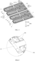
FIG. 1 is a schematic diagram of installation of two first collection mechanisms according to some embodiments of the present disclosure. -
FIG. 2 is an enlarged view of a portion A inFIG. 1 . -
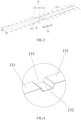
FIG. 3 is a perspective diagram of a collection assembly according to some embodiments of the present disclosure. -
FIG. 4 is an enlarged view of a portion B inFIG. 3 . -
FIG. 5 is a perspective diagram of a first connection member and a second connection member according to some embodiments of the present disclosure. -
FIG. 6 is a perspective diagram of a bracket according to some embodiments of the present disclosure. -
FIG. 7 is a schematic structural diagram of a cell grouping assembly according to some embodiments of the present disclosure. - 1. Battery module collection mechanism; 100. Collection group; 110. Serial assembly; 11. First serial group; 12. Second serial group; 101. First serial row; 102. Second serial row; 120. Collection assembly; 13. First collection line; 131. First connection portion; 132. First buffer portion; 133. First groove; 14. Second collection line; 141. Second connection portion; 142. Second buffer portion; 143. Second groove; 21. First connection member; 22. First integrated member; 23. Second integrated member; 24. Protrusion; 25. Recess; 3. Bracket; 31. Collection line installing groove; 32. Connection member installing groove; 4. Connection circuit board; 5. Cell grouping assembly; 51. Cell group.
- In description of the present disclosure, it should be noted that the terms "interconnection", "connection" and "fixing" should be understood in a broad sense, unless otherwise clearly specified and defined. For example, "fixing" can be a fixed connection, a detachable connection, or integrated connection. It can be a mechanical connection or an electrical connection. It can be directly connected or indirectly connected through an intermediary. It can also be the connection between two elements or the interaction between two elements. Those ordinary skilled in the art can understand the specific meanings of the above terms in the present disclosure according to specific situations.
- In the present disclosure, it should he noted that unless otherwise clearly defined and limited, a first feature "on" or "under" a second feature may mean that the first feature directly contacts the second feature, or that the first feature contacts the second feature via an additional feature there between instead of directly contacting the second feature. Moreover, the first feature "on", "above", and "over" the second feature may mean that the first feature is right over or obliquely upward over the second feature or mean that the first feature has a horizontal height higher than that of the second feature. The first feature "under", "below", and "beneath" the second feature may mean that the first feature is right beneath or obliquely downward beneath the second feature or mean that horizontal height of the first feature is lower than that of the second feature.
- In the description of the present embodiments, orientations or position relationships indicated by the terms "upper", "lower", "left", and "right" are based on orientations or position relationships illustrated in the drawings. The terms are used to facilitate and simplify the description and operations of the present disclosure, rather than indicate or imply that the devices or elements referred to herein are required to have specific orientations or be constructed or operate in the specific orientations. Accordingly, the terms should not be construed as limiting the present disclosure. In addition, the terms "first" and "second" are used solely for the purpose of distinguishing elements in terms of description of the elements and not in a particular sense.
- Referring to
FIGS. 1 and7 , a batterymodule collection mechanism 1 provided in the embodiments of the present disclosure may include: abracket 3; and acollection group 100 including aserial assembly 110 and acollection assembly 120; where theserial assembly 110 includes afirst serial group 11 and asecond serial group 12 both installed on thebracket 3, thefirst serial group 11 and thesecond serial group 12 each include a firstserial row 101 and asecond serial row 102 arranged oppositely in a first direction perpendicular to a second direction in which thefirst serial group 11 and thesecond serial group 12 is arranged, and each of thefirst serial group 11 and thesecond serial group 12 corresponds to onecell group 51; and thecollection assembly 120 includes afirst collection line 13 and asecond collection line 14 each installed on thebracket 3 and arranged oppositely in a direction in which thefirst collection line 13 and thesecond collection line 14 is arranged; and where two firstserial rows 101 of thefirst serial group 11 and thesecond serial group 12 are located at a side of thefirst collection line 13 away from thesecond collection line 14 and electrically connected to thefirst collection line 13, and twosecond serial rows 102 of thefirst serial group 11 and thesecond serial group 12 are located at a side of thesecond collection line 14 away from thefirst collection line 13 and electrically connected to thesecond collection line 14. - Firstly, the first
serial row 101 and the secondserial row 102 may be provided on thesame bracket 3, so that thecell groups 51 corresponding to the firstserial row 101 and the secondserial row 102 can be mounted more closely, thereby improving the space utilization rate. Secondly, the two firstserial rows 101 of the firstserial row 101 and the secondserial row 102 share thefirst collection line 13, and the two secondserial rows 102 of the firstserial row 101 and the secondserial row 102 share thesecond collection line 14, so that the use of the collection lines is reduced on the basis of the related art, thereby further reducing the use of the CSC assemblies to further save the use space, and improving the space energy density. - Referring to
FIGS. 1 and7 , a batterymodule collection mechanism 1 provided in the embodiments of the present disclosure may include: abracket 3; and acollection group 100. Thecollection group 100 may include aserial assembly 110 and acollection assembly 120. - The
serial assembly 110 may include a firstserial group 11, a secondserial group 12, and afirst connection member 21 all installed on thebracket 3. - The
collection assembly 120 may include afirst collection line 13 and asecond collection line 14 that both are installed on thebracket 3 and arranged oppositely in a direction in which thefirst collection line 13 and thesecond collection line 14 is arranged. - The first
serial group 11 may be configured to be connected in series with onecell group 51, and the secondserial group 12 may be configured to be connected in series with anothercell group 51. The firstserial group 11 and the secondserial group 12 may each include a firstserial row 101 and a secondserial row 102 arranged oppositely in a first direction perpendicular to a second direction in which the firstserial group 11 and the secondserial group 12 is arranged. The firstserial row 101 and the secondserial row 102 may be provided in the same number, the firstserial row 101 and the secondserial row 102 may be both configured to connect positive and negative electrodes of adjacent cells, and the firstserial row 101 and the secondserial row 102 may be configured to connect the positive and negative electrodes of the same cell. Thefirst connection member 21 may be disposed between the firstserial group 11 and the secondserial group 12 and configured to connect two secondserial rows 102 of the firstserial group 11 and the secondserial group 12 in series, and further connectscell groups 51 corresponding to the firstserial group 11 and the secondserial group 12 in series, thereby realizing integration of thecell group 51 corresponding to the firstserial group 11 with the cell group 71 corresponding to the secondserial group 12. - Referring to
FIGS. 1 and3 , thefirst collection line 13 and thesecond collection line 14 may be positioned between the firstserial row 101 and the secondserial row 102, thefirst collection line 13 may be electrically connected to the two firstserial rows 101 of the firstserial group 11 and the secondserial group 12, and thesecond collection line 14 may be electrically connected to the two secondserial rows 102 of the firstserial group 11 and the secondserial group 12. Thefirst collection line 13 and thesecond collection line 14 may be configured to collect voltage and temperature signals and the like of thecorresponding cell groups 51. - The
serial assembly 110 may further include twoconnection circuit boards 4 respectively connected to thefirst collection line 13 and thesecond collection line 14, where the twoconnection circuit boards 4 may be provided at one ends of thefirst collection line 13 and thesecond collection line 14, respectively, so as to facilitate connection with connectors of the CSC assembly. - Referring to
FIGS. 3 and 4 , thefirst collection line 13 may include twofirst connection portions 131 and afirst buffer portion 132 connected between the twofirst connection portions 131. The twofirst connection portions 131 may be connected to the two firstserial rows 101 of the firstserial group 11 and the secondserial group 12, respectively, and thefirst buffer portion 132 may be provided with afirst groove 133 facing thebracket 3. In an extension direction of thefirst collection line 13, a distance between thefirst groove 133 and the firstserial row 101 of the firstserial group 11 may be equal to a distance between thefirst groove 133 and the firstserial row 101 of the secondserial group 12. - The
second collection line 14 may include twosecond connection portions 141 and asecond buffer portion 142 connected between the twosecond connection portions 141, the twosecond connection portions 141 may be connected to the two secondserial rows 102 of the firstserial group 11 and the secondserial group 12, respectively, and thesecond buffer portion 142 may be provided with asecond groove 143 facing thebracket 3. In an extension direction of thesecond collection line 14, a distance between thesecond groove 143 and the secondserial row 102 of the firstserial group 11 may be equal to a distance between thesecond groove 143 and the secondserial row 102 of the secondserial group 12. As such, thefirst groove 133 and thesecond groove 143 both may be positioned between the firstserial row 101 and the secondserial row 102. When a cell of a battery module emits heat and is expanded, a tension force to which the twofirst connection portions 131 and the twosecond connection portions 141 are subjected from the cell is made as equal as possible, thereby enabling thefirst buffer portion 132 and thesecond buffer portion 142 to be stretched to a large extent to better adapt to expansion of the cell. - A virtual connection line between the center of the
first groove 133 and the center of thesecond groove 143 may be perpendicular to the extension direction of thefirst collection line 13, so that extension directions of thefirst buffer portion 132 and thesecond buffer portion 142 are the same as each other. - A cell expansion amount may be calculated by model simulation. For example, when the cell expansion amount is 1.5 mm, the lengths of the
first buffer portion 132 and thesecond buffer portion 142 are twice the cell expansion amount, that is, 3.0 mm. - Referring to
FIGS. 1 and5 , the first connection member is each provided with aprotrusion 24 away from thebracket 3 and tworecesses 25 on both sides of theprotrusion 24, where the tworecesses 25 are recessed toward thebracket 3, so that thefirst connection member 21 may have a W-shaped-like structure. When the cell emits heat and is expanded, thefirst connection member 21 can be expanded to accommodate the cell expansion amount. Additionally, compared with a solution in which thefirst connection member 21 is provided with onerecess 25, theprotrusion 24 may be provided between the tworecesses 25, which can improve a structural strength of thefirst connection member 21, and prevent thefirst connection member 21 from being broken away as much as possible without plastic deformation. Widths and depths of theprotrusion 24 and therecesses 25 may be determined according to actual cell expansion amount and a tensile force test. In the present embodiment, the size of thefirst connection member 21 is 114.4 mm*61 mm* 1.2 mm, and the depth of each of therecesses 25 is equal to the height of theprotrusion 24, which both are 3.5 mm. In the present embodiment, theserial assembly 110 may be made of aluminum, and thebracket 3 may be made of plastic. - Referring to
FIGS. 1 and7 , an embodiment of the present disclosure may further provide a battery module, including: the batterymodule collection mechanism 1 described in any one of the above embodiments, acell grouping assembly 5, and an integrated connection assembly. - The battery
module collection mechanism 1 may be provided in two, where the two batterymodule collection mechanisms 1 correspond to twocell grouping assemblies 5, respectively. Thecell grouping assembly 5 may include fourcell groups 51, and thecollection group 100 may be provided in two, where one of the twocollection groups 100 corresponds to two of the fourcell groups 51. The twocell groups 51 may be electrically connected to the firstserial group 11 and the secondserial group 12, respectively, and the integrated connection assembly may include a firstintegrated member 22 and a secondintegrated member 23. - When the
first connection member 21 may be connected to the two firstserial rows 101 of the firstserial group 11 and the secondserial group 12, the firstintegrated member 22 may be connected to the two secondserial rows 102 of the twocollection groups 100, the two secondserial rows 102 of the two firstserial groups 11 of the two batterymodule collection mechanisms 1 may be connected to each other through the secondintegrated member 23, and the secondintegrated member 23 may be provided on one side of the firstserial row 101 away from the firstintegrated member 22. - Alternatively, when the
first connection member 21 may be connected to the two secondserial rows 102 of the firstserial group 11 and the secondserial group 12, the firstintegrated member 22 may be connected to the two firstserial rows 101 of the twocollection groups 100, the two firstserial rows 102 of the two firstserial groups 11 of the two batterymodule collection mechanisms 1 may be connected to each other through the secondintegrated member 23, and the secondintegrated member 23 may be provided on one side of the firstserial row 101 away from the firstintegrated member 22. - In the present embodiment, the
first connection member 21 may be connected to the two secondserial rows 102 of the firstserial group 11 and the secondserial group 12. In this case, a flow path of a current of the battery module may be as follows: in one of thecollection groups 100, the current flows through thecell group 51 corresponding to the firstserial group 11 via the firstserial group 11 and the secondserial group 12 having the firstserial rows 101 connecting adjacent cells in series, and the current flows into a secondserial row 102 of the secondserial group 12 through the first connection member 21and flows through thecell group 51 corresponding to the secondserial group 12; then the current flows into a firstserial row 101 of a firstserial group 11 in another of thecollection groups 100 via the firstintegrated member 22, and flows through thecell group 51 corresponding to the firstserial group 11, the current flows into a secondserial row 102 of a secondserial group 12 through thefirst connection member 21 and flows through thecell group 51 corresponding to the second serial group; and finally, the current flows into a firstserial row 101 of a firstserial group 11 of another batterymodule collection mechanism 1 through the secondintegrated member 23. - In other embodiments, two
first connectors 21 of twocollection groups 100 may connect two firstserial rows 101 or two secondserial rows 102, respectively. - Integration of the four
cell groups 51 may be achieved by thefirst connection member 21 and the firstintegrated member 22, and the four battery modules may be integrated into one larger battery module, thereby increasing the energy density. By extending the collection line on the original basis, the number of CSC assemblies may be reduced, thereby reducing the intermediate transfer harness. - In other embodiments, the
battery grouping assembly 5 may also be provided in three, four or even more, the batterymodule collection mechanism 1 may be provided in a number corresponding to the number of thebattery grouping assemblies 5, and thecollection group 100 may also be provided in three, four or even more.Cell grouping groups 5 corresponding to different batterymodule collection mechanisms 1 may be electrically connected through the secondintegrated member 23, and thedifferent collection groups 100 may be electrically connected through the firstintegrated member 22. - Referring to
FIG. 6 , thebracket 3 may be provided with four collectionline installing grooves 31 for installingcollection assemblies 120 and a connectionmember installing groove 32 for installing thefirst connection member 21, and the collectionline installing grooves 31 and the connectionmember installing groove 32 may be designed according to shapes of the collection assemblies and the connection member.
Claims (13)
- A battery module collection mechanism (1), characterized in that the battery module collection mechanism (1) comprises:a bracket (3); anda collection group (100) comprising a serial assembly (110) and a collection assembly (120), wherein the serial assembly (110) comprises a first serial group (11) and a second serial group (12) both installed on the bracket (3), the first serial group (11) and the second serial group (12) each comprises a first serial row (101) and a second serial row (102) arranged oppositely in a first direction perpendicular to a second direction in which the first serial group and the second serial group is arranged, and the first serial group (11) and the second serial group (12) each corresponds to a cell group (51); and the collection assembly (120) comprises a first collection line (13) and a second collection line (14) each installed on the bracket (3) and arranged oppositely in a direction in which the first collection line and the second collection line is arranged; andwherein two first serial rows (101) of both the first serial group (11) and the second serial group (12) are located at a side of the first collection line (13) away from the second collection line (14) and electrically connected to the first collection line (13), and two second serial rows (102) of both the first serial group (11) and the second serial group (12) are located at a side of the second collection line (14) away from the first collection line (13) and electrically connected to the second collection line (14).
- The battery module collection mechanism (1) of claim 1, characterized in that the first collection line (13) comprises two first connection portions (131) and a first buffer portion (132) connected between the two first connection portions (131), the two first connection portions (131) are connected to the two first serial rows (101) of both the first serial group (11) and the second serial group (12), respectively, and the first buffer portion (132) is provided with a first groove (133) toward the bracket (3); and
the second collection line (14) comprises two second connection portions (141) and a second buffer portion (142) connected between the two second connection portions (141), the two second connection portions (141) are connected to the two second serial rows (102) of both the first serial group (11) and the second serial group (12), respectively, and the second buffer portion (142) is provided with a second groove (143) toward the bracket (3). - The battery module collection mechanism (1) of claim 2, characterized in that, in an extension direction of the first collection line (13), a distance between the first groove (133) and the first serial row (101) of the first serial group (11) is equal to a distance between the first groove (133) and the first serial row (101) of the second serial group (12); and in an extension direction of the second collection line (14), a distance between the second groove (143) and the second serial row (102) of the first serial group (11) is equal to a distance between the second groove (143) and the second serial row (102) of the second serial group (12).
- The battery module collection mechanism (1) of claim 3, characterized in that a virtual connection line between a center of the second groove (143) and a center of the first groove (133) is perpendicular to the extension direction of the first collection line (13).
- The battery module collection mechanism (1) of any of claims 1-4, characterized in that the serial assembly (110) further comprises a first connection member (21) for connecting the first serial group (11) and the second serial group (12).
- The battery module collection mechanism (1) of claim 5, characterized in that the first collection member (21) is connected between two first serial rows (101) of both the first serial group (11) and the second serial group (12) or connected between two second serial rows (102) of both the first serial group (11) and the second serial group (12); and the first connection member (21) is provided with a protrusion (24) away from the bracket (3).
- The battery module collection mechanism (1) of claim 6, characterized in that the first connection member (21) is provided with two recesses (25) on both sides of the protrusion (24), and the two recesses (25) are recessed toward the bracket (3).
- The battery module collection mechanism (1) of claim 7, characterized in that a depth of each of the recesses (25) is equal to a height of the protrusion (24).
- The battery module collection mechanism (1) of claim 1, characterized in that the serial assembly (110) comprises two connection circuit boards (4) respectively connected to the first collection line (13) and the second collection line (14).
- The battery module collection mechanism (1) of claim 1, characterized in that the bracket (3) are provided with a plurality of collection line installing grooves (31) for installing collection assemblies (120) and a connection member installing groove (32) for installing the first connection member (21), wherein the collection line installing grooves (31) and the connection member installing groove (32) are designed based on shapes of the collection assemblies (120) and the connection member (21).
- A battery module, characterized in that the battery module comprises two or more cell grouping assemblies (5) and the battery module collection mechanism (1) of any one of claims 1 to 10 provided in a number corresponding to a number of the cell grouping assemblies (5), wherein each of the cell grouping assemblies (5) comprises two or more cell groups (51), and the two cell groups (51) are electrically connected to the first serial group (11) and the second serial group (12), respectively; and
the serial assembly (110) further comprises a first connection member (21) for connecting the first serial group (11) and the second serial group (12), wherein the first connection member is configured to connect the two cell groups (51) in series. - The battery module of claim 11, characterized in that the battery module further comprises an integrated connection assembly comprising a first integrated member (22), wherein each of the cell grouping assemblies (5) comprises four cell groups (51), the collection group (100) is provided in two, the first integrated member (22) is configured to connect the two second serial rows (102) of the two collection groups (100) when the first connection member (21) is configured to connect the two first serial row (101) of both the first serial group (11) and the second serial group (12), and the first integrated member (22) is configured to connect the two first serial rows (101) of the two collection groups (100) when the first connection member (21) is configured to connect the two second serial row (102) of both the first serial group (11) and the second serial group (12).
- The battery module of claim 12, characterized in that the integrated connection assembly further comprises a second integrated member (23) disposed on a side of the first serial row (101) away from the first integrated member (22), the two second serial rows (102) of the two first serial groups (11) of the two battery module collection mechanisms (1) are interconnected with each other by the second integrated member (23) when the first connection member (21) is configured to connect the two first serial rows (101) of both the first serial group (11) and the second serial group (12), and the two first serial rows (101) of the two first serial groups (11) of the two battery module collection mechanisms (1) are interconnected with each other by the second integrated member (23) when the first connection member (21) is configured to connect the two second serial rows (102) of both the first serial group (11) and the second serial group (12).
Applications Claiming Priority (3)
| Application Number | Priority Date | Filing Date | Title |
|---|---|---|---|
| CN202311749998.0A CN117748054A (en) | 2023-12-18 | 2023-12-18 | Battery module and collection mechanism thereof |
| CN202323464344.1U CN221994658U (en) | 2023-12-18 | 2023-12-18 | Battery module and collection mechanism thereof |
| PCT/CN2024/090978 WO2025129890A1 (en) | 2023-12-18 | 2024-04-30 | Battery module and acquisition mechanism thereof |
Publications (1)
| Publication Number | Publication Date |
|---|---|
| EP4576397A1 true EP4576397A1 (en) | 2025-06-25 |
Family
ID=93150652
Family Applications (1)
| Application Number | Title | Priority Date | Filing Date |
|---|---|---|---|
| EP24206962.3A Pending EP4576397A1 (en) | 2023-12-18 | 2024-10-16 | Battery module and battery module collection mechanism |
Country Status (2)
| Country | Link |
|---|---|
| US (1) | US20250202068A1 (en) |
| EP (1) | EP4576397A1 (en) |
Citations (2)
| Publication number | Priority date | Publication date | Assignee | Title |
|---|---|---|---|---|
| CN117013182A (en) * | 2023-07-24 | 2023-11-07 | 厦门科华数能科技有限公司 | A kind of battery module and battery pack |
| WO2024174833A1 (en) * | 2023-02-21 | 2024-08-29 | 江苏正力新能电池技术有限公司 | Battery assembly and battery pack |
-
2024
- 2024-10-16 EP EP24206962.3A patent/EP4576397A1/en active Pending
- 2024-11-28 US US18/963,613 patent/US20250202068A1/en active Pending
Patent Citations (2)
| Publication number | Priority date | Publication date | Assignee | Title |
|---|---|---|---|---|
| WO2024174833A1 (en) * | 2023-02-21 | 2024-08-29 | 江苏正力新能电池技术有限公司 | Battery assembly and battery pack |
| CN117013182A (en) * | 2023-07-24 | 2023-11-07 | 厦门科华数能科技有限公司 | A kind of battery module and battery pack |
Also Published As
| Publication number | Publication date |
|---|---|
| US20250202068A1 (en) | 2025-06-19 |
Similar Documents
| Publication | Publication Date | Title |
|---|---|---|
| CN117748054A (en) | Battery module and collection mechanism thereof | |
| US20250183495A1 (en) | Battery pack and electricity-consumption device | |
| CN219067174U (en) | A battery pack and electric vehicle | |
| CN219476774U (en) | Integrated CCS assembly and battery pack | |
| WO2018080181A1 (en) | Connector for printed circuit board and battery system comprising printed circuit board and connector | |
| CN117393949A (en) | CCS assembly and battery pack | |
| EP4576397A1 (en) | Battery module and battery module collection mechanism | |
| CN218782309U (en) | Signal acquisition device and battery module | |
| EP4576399A1 (en) | Battery module and battery module collection mechanism | |
| CN220773100U (en) | Linkage type acquisition module for contact sampling near-end conduction | |
| CN221508374U (en) | End plate assembly and battery pack | |
| US20240014453A1 (en) | Battery device assembling method and battery device | |
| CN221994658U (en) | Battery module and collection mechanism thereof | |
| WO2024113949A1 (en) | Signal acquisition assembly and battery module | |
| CN222126650U (en) | Battery module and collection mechanism thereof | |
| CN212136571U (en) | Flexible circuit board, electric core information acquisition system and battery pack | |
| WO2025129890A1 (en) | Battery module and acquisition mechanism thereof | |
| US20250167376A1 (en) | Battery module and vehicle | |
| CN223066421U (en) | A battery cell data acquisition structure | |
| CN219144420U (en) | Battery line concentration box and energy storage battery assembly | |
| US20260038951A1 (en) | Acquisition assembly, battery module, and battery box | |
| CN223463173U (en) | FPC structure and group battery | |
| CN215119163U (en) | Bus bar integrated bus bar | |
| CN223309165U (en) | CCS component for multi-cell module of power battery | |
| CN223927580U (en) | Integrated busbar, battery cell module and energy storage battery pack |
Legal Events
| Date | Code | Title | Description |
|---|---|---|---|
| PUAI | Public reference made under article 153(3) epc to a published international application that has entered the european phase |
Free format text: ORIGINAL CODE: 0009012 |
|
| STAA | Information on the status of an ep patent application or granted ep patent |
Free format text: STATUS: REQUEST FOR EXAMINATION WAS MADE |
|
| 17P | Request for examination filed |
Effective date: 20241016 |
|
| AK | Designated contracting states |
Kind code of ref document: A1 Designated state(s): AL AT BE BG CH CY CZ DE DK EE ES FI FR GB GR HR HU IE IS IT LI LT LU LV MC ME MK MT NL NO PL PT RO RS SE SI SK SM TR |