EP4576378A1 - Battery unit structure and vehicle comprising same - Google Patents
Battery unit structure and vehicle comprising same Download PDFInfo
- Publication number
- EP4576378A1 EP4576378A1 EP24757274.6A EP24757274A EP4576378A1 EP 4576378 A1 EP4576378 A1 EP 4576378A1 EP 24757274 A EP24757274 A EP 24757274A EP 4576378 A1 EP4576378 A1 EP 4576378A1
- Authority
- EP
- European Patent Office
- Prior art keywords
- battery
- unit structure
- venting
- battery unit
- structure according
- Prior art date
- Legal status (The legal status is an assumption and is not a legal conclusion. Google has not performed a legal analysis and makes no representation as to the accuracy of the status listed.)
- Pending
Links
Images



Classifications
-
- H—ELECTRICITY
- H01—ELECTRIC ELEMENTS
- H01M—PROCESSES OR MEANS, e.g. BATTERIES, FOR THE DIRECT CONVERSION OF CHEMICAL ENERGY INTO ELECTRICAL ENERGY
- H01M50/00—Constructional details or processes of manufacture of the non-active parts of electrochemical cells other than fuel cells, e.g. hybrid cells
- H01M50/30—Arrangements for facilitating escape of gases
-
- H—ELECTRICITY
- H01—ELECTRIC ELEMENTS
- H01M—PROCESSES OR MEANS, e.g. BATTERIES, FOR THE DIRECT CONVERSION OF CHEMICAL ENERGY INTO ELECTRICAL ENERGY
- H01M50/00—Constructional details or processes of manufacture of the non-active parts of electrochemical cells other than fuel cells, e.g. hybrid cells
- H01M50/20—Mountings; Secondary casings or frames; Racks, modules or packs; Suspension devices; Shock absorbers; Transport or carrying devices; Holders
- H01M50/204—Racks, modules or packs for multiple batteries or multiple cells
-
- H—ELECTRICITY
- H01—ELECTRIC ELEMENTS
- H01M—PROCESSES OR MEANS, e.g. BATTERIES, FOR THE DIRECT CONVERSION OF CHEMICAL ENERGY INTO ELECTRICAL ENERGY
- H01M50/00—Constructional details or processes of manufacture of the non-active parts of electrochemical cells other than fuel cells, e.g. hybrid cells
- H01M50/20—Mountings; Secondary casings or frames; Racks, modules or packs; Suspension devices; Shock absorbers; Transport or carrying devices; Holders
- H01M50/249—Mountings; Secondary casings or frames; Racks, modules or packs; Suspension devices; Shock absorbers; Transport or carrying devices; Holders specially adapted for aircraft or vehicles, e.g. cars or trains
-
- H—ELECTRICITY
- H01—ELECTRIC ELEMENTS
- H01M—PROCESSES OR MEANS, e.g. BATTERIES, FOR THE DIRECT CONVERSION OF CHEMICAL ENERGY INTO ELECTRICAL ENERGY
- H01M50/00—Constructional details or processes of manufacture of the non-active parts of electrochemical cells other than fuel cells, e.g. hybrid cells
- H01M50/30—Arrangements for facilitating escape of gases
- H01M50/342—Non-re-sealable arrangements
-
- H—ELECTRICITY
- H01—ELECTRIC ELEMENTS
- H01M—PROCESSES OR MEANS, e.g. BATTERIES, FOR THE DIRECT CONVERSION OF CHEMICAL ENERGY INTO ELECTRICAL ENERGY
- H01M50/00—Constructional details or processes of manufacture of the non-active parts of electrochemical cells other than fuel cells, e.g. hybrid cells
- H01M50/30—Arrangements for facilitating escape of gases
- H01M50/342—Non-re-sealable arrangements
- H01M50/3425—Non-re-sealable arrangements in the form of rupturable membranes or weakened parts, e.g. pierced with the aid of a sharp member
-
- H—ELECTRICITY
- H01—ELECTRIC ELEMENTS
- H01M—PROCESSES OR MEANS, e.g. BATTERIES, FOR THE DIRECT CONVERSION OF CHEMICAL ENERGY INTO ELECTRICAL ENERGY
- H01M50/00—Constructional details or processes of manufacture of the non-active parts of electrochemical cells other than fuel cells, e.g. hybrid cells
- H01M50/30—Arrangements for facilitating escape of gases
- H01M50/394—Gas-pervious parts or elements
-
- H—ELECTRICITY
- H01—ELECTRIC ELEMENTS
- H01M—PROCESSES OR MEANS, e.g. BATTERIES, FOR THE DIRECT CONVERSION OF CHEMICAL ENERGY INTO ELECTRICAL ENERGY
- H01M2220/00—Batteries for particular applications
- H01M2220/20—Batteries in motive systems, e.g. vehicle, ship, plane
-
- Y—GENERAL TAGGING OF NEW TECHNOLOGICAL DEVELOPMENTS; GENERAL TAGGING OF CROSS-SECTIONAL TECHNOLOGIES SPANNING OVER SEVERAL SECTIONS OF THE IPC; TECHNICAL SUBJECTS COVERED BY FORMER USPC CROSS-REFERENCE ART COLLECTIONS [XRACs] AND DIGESTS
- Y02—TECHNOLOGIES OR APPLICATIONS FOR MITIGATION OR ADAPTATION AGAINST CLIMATE CHANGE
- Y02E—REDUCTION OF GREENHOUSE GAS [GHG] EMISSIONS, RELATED TO ENERGY GENERATION, TRANSMISSION OR DISTRIBUTION
- Y02E60/00—Enabling technologies; Technologies with a potential or indirect contribution to GHG emissions mitigation
- Y02E60/10—Energy storage using batteries
Definitions
- the present disclosure relates to a battery unit structure and a vehicle including the same, and more specifically, it relates to a battery unit structure in which a venting area expands due to rupture caused by increased internal pressure even if a mesh portion is clogged with materials (e.g., spark materials including metals and active materials included in electrodes) generated by events such as thermal runaway, thereby discharging gas and preventing ejection of materials and flame, and a vehicle including the same.
- materials e.g., spark materials including metals and active materials included in electrodes
- lithium secondary batteries are in the spotlight for their advantages of free charging and discharging due to almost no memory effect, a very low self-discharge rate, and a high energy density, compared to nickel-based secondary batteries.
- lithium secondary batteries generally use lithium-based oxides and carbon materials as positive and negative electrode active materials, respectively.
- the lithium secondary batteries an electrode assembly in which positive and negative electrode plates, coated with the positive and negative electrode active materials, respectively, are disposed with a separator therebetween, and an exterior case, i.e., a battery case, that seals and stores the electrode assembly with an electrolyte.
- втори ⁇ ество have been widely used for driving or energy storage in electric vehicles and medium to large devices such as energy storage systems (ESSs), as well as in small devices such as portable electronic devices.
- Multiple secondary batteries may be electrically connected to each other and stored inside a module case to form a battery module, and these battery modules and/or battery cells may be electrically connected in a narrow space to increase energy density, thereby producing a battery pack.
- existing battery unit structures such as battery modules or battery packs, have a venting hole for discharging gas when an event such as thermal runaway occurs therein and a mesh member to prevent the discharge of materials such as spark materials including metals and active materials included in the electrodes during venting.
- the present disclosure has been designed to solve the problems of the related art, and therefore the present disclosure is directed to providing a battery unit structure configured such that a venting area expands due to rupture caused by increased internal pressure even if the venting hole is clogged with materials generated by events such as thermal runaway, thereby discharging gas and preventing ejection of materials and flame.
- a battery unit structure that includes: a battery cell; a battery housing having an accommodation space configured to accommodate the battery cell therein and including a venting portion configured to discharge gas generated from the battery cell on at least one side thereof; and a battery cover configured to cover the battery cell, wherein the venting portion may include: a discharge portion including a venting hole configured to discharge the gas and a rupture portion configured to rupture if internal pressure of the accommodation space reaches a predetermined pressure or more; and a mesh portion positioned to face the accommodation space with the discharge portion therebetween.
- the venting hole may be configured to overlap a portion of the mesh portion.
- the rupture portion may be located adjacent to the venting hole.
- the rupture portion may include a plurality of vulnerable portions configured to have lower strength than surrounding portions.
- the plurality of vulnerable portions may be formed along at least one straight line having a predetermined length.
- the plurality of vulnerable portions may be formed to be spaced a predetermined distance apart from each other.
- the venting portion may include a guide portion configured to guide the gas from the venting hole to the mesh portion.
- the guide portion may protrude from the perimeter of the venting hole toward the mesh portion.
- a vehicle including the battery unit structure according to the present disclosure.
- the venting area is preferentially designed to be small at the beginning and configured to expand by rupture when the mesh portion is clogged, thereby minimizing the inflow of oxygen and facilitating gas discharge.
- the venting area may expand by rupture to continuously and effectively discharge gas and prevent ejection of spark materials and/or flame.
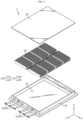
- FIG. 1 is a perspective view illustrating the appearance of a battery unit structure according to the present disclosure.
- FIG. 2 is an exploded perspective view illustrating a battery unit structure according to the present disclosure.
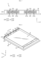
- FIG. 3 is a diagram illustrating a battery housing included in a battery unit structure according to the present disclosure.
- the battery cover 30 may be configured to cover the battery cells 10.
- the battery cover 30 may have a plate shape.
- the battery cover 30 may be coupled to the battery housing 20 so as to cover the battery cells 10.
- the battery cover 30 may be coupled to the battery housing 20 so as to cover the accommodation space 21.
- the coupling may be performed by bolting or welding.
- FIGS. 4 and 5 are front views of a battery housing included in a battery unit structure according to the present disclosure.
- the venting portion 22 may include a discharge portion 220 and a mesh portion 230.
- the discharge portion 220 may include a venting hole 221 and a rupture portion 222.
- the venting hole 221 may be configured to discharge gas.
- the venting hole 221 may be configured in the form of a simple hole passing through the battery housing 20.
- the venting hole 221 is not limited to a completely open-type hole.
- the venting hole 221 may be configured to be closed in a normal state, instead of being completely open, and to open depending on a change in pressure or temperature.
- the venting hole 221 may be a hole configured to be open and closed according to the pressure of gas generated inside the battery housing 20 by applying a one-way valve.
- the rupture portion 222 may be configured to rupture if the internal pressure of the accommodation space 21 reaches a predetermined pressure or more.
- the rupture portion 222 may be configured to have lower strength than the surrounding portions.
- the rupture portion 222 may indicate a specific area configured to have lower strength than the surrounding portions.
- the mesh portion 230 may be configured to discharge gas among the materials generated during venting of the battery cell 10 and prevent spark materials including metals and active materials included in electrodes from being discharged.
- the mesh portion 230 may be a mesh configured in a dense lattice.
Landscapes
- Chemical & Material Sciences (AREA)
- Chemical Kinetics & Catalysis (AREA)
- Electrochemistry (AREA)
- General Chemical & Material Sciences (AREA)
- Engineering & Computer Science (AREA)
- Aviation & Aerospace Engineering (AREA)
- Gas Exhaust Devices For Batteries (AREA)
- Battery Mounting, Suspending (AREA)
- Sealing Battery Cases Or Jackets (AREA)
Abstract
Description
- The present disclosure relates to a battery unit structure and a vehicle including the same, and more specifically, it relates to a battery unit structure in which a venting area expands due to rupture caused by increased internal pressure even if a mesh portion is clogged with materials (e.g., spark materials including metals and active materials included in electrodes) generated by events such as thermal runaway, thereby discharging gas and preventing ejection of materials and flame, and a vehicle including the same.
- The present application claims priority to
Korean Patent Application No. 10-2023-0020357 filed on February 15, 2023 - As the demand for portable electronic products such as laptops, video cameras, and portable phones is rapidly increased, and as the commercialization of robots and electric vehicles, or the like is accelerated, active researches on high-performance secondary batteries capable of being repeated charged and discharged are underway.
- Currently commercialized secondary batteries include nickel-cadmium batteries, nickel-hydrogen batteries, nickel-zinc batteries, and lithium secondary batteries. Among these, lithium secondary batteries are in the spotlight for their advantages of free charging and discharging due to almost no memory effect, a very low self-discharge rate, and a high energy density, compared to nickel-based secondary batteries.
- These lithium secondary batteries generally use lithium-based oxides and carbon materials as positive and negative electrode active materials, respectively. The lithium secondary batteries an electrode assembly in which positive and negative electrode plates, coated with the positive and negative electrode active materials, respectively, are disposed with a separator therebetween, and an exterior case, i.e., a battery case, that seals and stores the electrode assembly with an electrolyte.
- Meanwhile, lithium secondary batteries may be classified, depending on the shape of a battery case, into can-type secondary batteries in which the electrode assembly is accommodated in a metal can and pouch-type secondary batteries in which the electrode assembly is accommodated in a pouch of an aluminum laminate sheet.
- Recently, secondary batteries have been widely used for driving or energy storage in electric vehicles and medium to large devices such as energy storage systems (ESSs), as well as in small devices such as portable electronic devices. Multiple secondary batteries may be electrically connected to each other and stored inside a module case to form a battery module, and these battery modules and/or battery cells may be electrically connected in a narrow space to increase energy density, thereby producing a battery pack.
- However, if a large number of battery modules and/or battery cells are densely stored in a small space, they may be vulnerable to accidents such as fire or explosion. Therefore, existing battery unit structures, such as battery modules or battery packs, have a venting hole for discharging gas when an event such as thermal runaway occurs therein and a mesh member to prevent the discharge of materials such as spark materials including metals and active materials included in the electrodes during venting.
- However, the venting hole and the mesh member are clogged with the materials generated when an event such as thermal runaway occurs so that internal pressure excessively increases, causing fire or explosion in the battery unit structure. Therefore, a new battery unit structure having a structure to solve the above problems is required to be developed.
- The present disclosure has been designed to solve the problems of the related art, and therefore the present disclosure is directed to providing a battery unit structure configured such that a venting area expands due to rupture caused by increased internal pressure even if the venting hole is clogged with materials generated by events such as thermal runaway, thereby discharging gas and preventing ejection of materials and flame.
- However, the technical problems that the present disclosure seeks to solve are not limited to the above-mentioned problems, and other problems not mentioned above will be clearly understood by those skilled in the art from the description of the invention described below.
- According to one aspect of the present disclosure, there is provided a battery unit structure that includes: a battery cell; a battery housing having an accommodation space configured to accommodate the battery cell therein and including a venting portion configured to discharge gas generated from the battery cell on at least one side thereof; and a battery cover configured to cover the battery cell, wherein the venting portion may include: a discharge portion including a venting hole configured to discharge the gas and a rupture portion configured to rupture if internal pressure of the accommodation space reaches a predetermined pressure or more; and a mesh portion positioned to face the accommodation space with the discharge portion therebetween.
- The venting hole may be configured to overlap a portion of the mesh portion.
- The rupture portion may be configured to overlap a portion of the mesh portion.
- The mesh portion may be configured to discharge gas among materials generated during venting of the battery cell and prevent spark materials including metals and active materials included in electrodes from being discharged.
- The rupture portion may be located adjacent to the venting hole.
- The rupture portion may include a plurality of vulnerable portions configured to have lower strength than surrounding portions.
- The plurality of vulnerable portions may be formed along at least one straight line having a predetermined length.
- The plurality of vulnerable portions may be formed to be spaced a predetermined distance apart from each other.
- The venting portion may include a guide portion configured to guide the gas from the venting hole to the mesh portion.
- The guide portion may protrude from the perimeter of the venting hole toward the mesh portion.
- According to another aspect of the present disclosure, there is provided a vehicle including the battery unit structure according to the present disclosure.
- According to one aspect of the present disclosure, in the battery unit structure, the venting area is preferentially designed to be small at the beginning and configured to expand by rupture when the mesh portion is clogged, thereby minimizing the inflow of oxygen and facilitating gas discharge.
- According to another aspect of the present disclosure, even if spark materials that may be generated with gas block the mesh member during venting, the venting area may expand by rupture to continuously and effectively discharge gas and prevent ejection of spark materials and/or flame.
- However, the effects obtainable from the present disclosure are not limited to the above-mentioned effects, and other effects not mentioned above will be clearly understood by those skilled in the art from the description of the invention described below.
- The accompanying drawings illustrate a preferred embodiment of the present disclosure and, together with the detailed description of the invention, serve to provide further understanding of the technical idea of the present disclosure, and thus, the present disclosure is not construed as being limited to the drawings.
-
FIG. 1 is a perspective view illustrating the appearance of a battery unit structure according to the present disclosure. -
FIG. 2 is an exploded perspective view illustrating a battery unit structure according to the present disclosure. -
FIG. 3 is a diagram illustrating a battery housing included in a battery unit structure according to the present disclosure. -
FIGS. 4 to 7 are front views of a battery housing included in a battery unit structure according to the present disclosure. -
FIG. 8 is a diagram illustrating a battery housing included in a battery unit structure according to the present disclosure. -
FIG. 9 is a schematically cross-sectional view taken by way of example along line A-A' inFIG. 8 . -
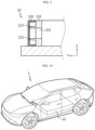
FIG. 10 is a diagram illustrating a vehicle according to the present disclosure. - Hereinafter, preferred embodiments of the present disclosure will be described in detail with reference to the accompanying drawings. The accompanying drawings illustrate a preferred embodiment of the present disclosure and, together with the detailed description of the invention, serve to provide further understanding of the technical idea of the present disclosure, and thus, the present disclosure is not construed as being limited to the drawings. The same reference numerals indicate the same elements in the attached drawings. In addition, the thicknesses, ratios, and sizes of the elements in the attached drawings may be exaggerated in order to effectively explain the technical features of the present disclosure.
- It should be understood that the terms used in the specification and the appended claims should not be construed as limited to general and dictionary meanings, but interpreted based on the meanings and concepts corresponding to technical aspects of the present disclosure on the basis of the principle that the inventor is allowed to define terms appropriately for the best explanation.
- Although terms indicating directions such as upward, downward, left, right, forward, and backward directions are used in this specification, it is obvious to those skilled in the art that these terms are only for convenience of explanation and may vary depending on the position of the target object or the position of the observer.
- Therefore, the configurations proposed in the embodiments and drawings of this specification indicate only the most preferable embodiment of the present disclosure and do not represent all technical ideas of the present disclosure, so it should be understood that various equivalents and modifications could be made thereto at the time of filing the application.
-
FIG. 1 is a perspective view illustrating the appearance of a battery unit structure according to the present disclosure.FIG. 2 is an exploded perspective view illustrating a battery unit structure according to the present disclosure.FIG. 3 is a diagram illustrating a battery housing included in a battery unit structure according to the present disclosure. - Referring to
FIGS. 1 to 3 , abattery unit structure 2 according to the present disclosure may include abattery cell 10, abattery housing 20, and abattery cover 30. - A plurality of
battery cells 10 may be provided. Thebattery cell 10 may indicate a secondary battery. Thebattery cell 10 may include an electrode assembly, an electrolyte, a battery case accommodating the electrode assembly and the electrolyte, and a pair of electrode leads connected to the electrode assembly and extending to the outside of the battery case. Thebattery cell 10 may be, for example, a pouch-type secondary battery. However, other types of secondary batteries, such as cylindrical batteries or prismatic batteries, may also be applied to thebattery cell 10 in the present disclosure. - The
battery housing 20 may have anaccommodation space 21 and aventing portion 22. Theaccommodation space 21 may be configured to accommodate thebattery cells 10 therein. Theventing portion 22 may be provided on at least one side of thebattery housing 20. Theventing portion 22 may be configured to discharge gas generated from thebattery cells 10 to the outside of thebattery housing 20. The ventingportion 22 may be provided at a position where gas generated inside thebattery unit structure 2 is required to be discharged. A plurality of ventingportions 22 may be provided. - The
battery cover 30 may be configured to cover thebattery cells 10. Thebattery cover 30 may have a plate shape. Thebattery cover 30 may be coupled to thebattery housing 20 so as to cover thebattery cells 10. Thebattery cover 30 may be coupled to thebattery housing 20 so as to cover theaccommodation space 21. The coupling may be performed by bolting or welding. -
FIGS. 4 and5 are front views of a battery housing included in a battery unit structure according to the present disclosure. - Referring to
FIGS. 4 and5 , the ventingportion 22 may include adischarge portion 220 and amesh portion 230. - The
discharge portion 220 may include aventing hole 221 and arupture portion 222. - The
venting hole 221 may be configured to discharge gas. Theventing hole 221 may be configured in the form of a simple hole passing through thebattery housing 20. However, the ventinghole 221 is not limited to a completely open-type hole. Theventing hole 221 may be configured to be closed in a normal state, instead of being completely open, and to open depending on a change in pressure or temperature. For example, the ventinghole 221 may be a hole configured to be open and closed according to the pressure of gas generated inside thebattery housing 20 by applying a one-way valve. - The
rupture portion 222 may be configured to rupture if the internal pressure of theaccommodation space 21 reaches a predetermined pressure or more. Therupture portion 222 may be configured to have lower strength than the surrounding portions. Therupture portion 222 may indicate a specific area configured to have lower strength than the surrounding portions. - The
mesh portion 230 may face theaccommodation space 21 with thedischarge portion 220 therebetween. Themesh portion 230 may be provided on the outermost side of thebattery housing 20. Themesh portions 230 may be mesh members provided in the respective areas corresponding to theventing hole 221 and therupture portion 222. Themesh portion 230 may be configured to cover the entire area corresponding to theventing hole 221 and therupture portion 222. Themesh portion 230 may have a plate shape disposed to face thedischarge portion 220. Themesh portion 230 may be a member provided separately from thedischarge portion 220. Themesh portions 230 may include mesh members provided in the respective areas corresponding to theventing hole 221 and therupture portion 222. Themesh portion 230 and theventing hole 221 may have a predetermined space therebetween. - The
mesh portion 230 may be configured to discharge gas among the materials generated during venting of thebattery cell 10 and prevent spark materials including metals and active materials included in electrodes from being discharged. Themesh portion 230 may be a mesh configured in a dense lattice. - The
venting hole 221 may be configured to overlap a portion of themesh portion 230. Theventing hole 221 may be entirely covered by themesh portion 230. At least a portion of the remaining area of themesh portion 230, excluding the area overlapping theventing hole 221, may be configured to overlap therupture portion 222. - The
rupture portion 222 may be configured to overlap a portion of themesh portion 230. Therupture portion 222 may be entirely covered by themesh portion 230. At least a portion of the remaining area of themesh portion 230, excluding the area overlapping therupture portion 222, may be configured to overlap theventing hole 221. - The
battery unit structure 2 according to the present disclosure described above may be a battery module. The battery module may include, for example, a cell assembly including a plurality ofbattery cells 10 electrically connected to each other and a module housing for accommodating the cell assembly. However, thebattery unit structure 2 of the present disclosure is not limited thereto. Thebattery unit structure 2 may be a battery pack. Such a battery pack may be a battery pack manufactured through a cell-to-pack process without going through a process of manufacturing the battery modules, as well as a battery pack including a plurality of battery modules. That is, the ventingportion 22 according to the present disclosure may be provided in the battery module housing and/or pack housing. - If the
venting hole 221 provided in the battery module housing and/or pack housing is designed to be large to include the area corresponding to therupture portion 222 at the beginning, gas discharge is easy, but oxygen easily flows in from the outside, thereby increasing the risk of fire. - However, according to this structure of the present disclosure, the venting area may not be designed to be large at the beginning. The venting area may be designed to expand by the rupture of the
rupture portion 222 if themesh portion 230 is clogged, thereby solving the above problem. In addition, in the case where gas and spark materials including metal and active materials included in the electrodes are generated due to an event such as thermal runaway inside thebattery unit structure 2, even if themesh portion 230 is clogged with the spark materials that may be generated along with the gas during venting, the venting area may expand by rupture of therupture portion 222, thereby continuously and effectively discharging gas and preventing ejection of the spark materials and/or flame. - Referring back to
FIG. 5 , therupture portion 222 may be located adjacent to theventing hole 221. According to this configuration, if themesh portion 230 is clogged, therupture portion 222 may more easily rupture by the gas heading toward theventing hole 221. -
FIGS. 6 and7 are front views of a battery housing included in a battery unit structure according to the present disclosure. - Referring to
FIGS. 6 and7 , therupture portion 222 may include a plurality ofvulnerable portions 222a. - The plurality of
vulnerable portions 222a may be configured to have lower strength than the surrounding portions. Each of the plurality ofvulnerable portions 222a may be an area formed to be thinner than the surrounding area by grooves having a predetermined length. The plurality ofvulnerable portions 222a may be formed along at least one straight line having a predetermined length. Referring toFIG. 6 , the plurality ofvulnerable portions 222a may be formed along a straight line having a predetermined length in the X-axis direction. The plurality ofvulnerable portions 222a may be formed to be spaced a predetermined distance apart from each other. On the other hand, the plurality ofvulnerable portions 222a may be formed continuously, instead of being spaced apart from each other. - In another aspect, the plurality of
vulnerable portions 222a may be formed substantially in a closed loop, instead of the straight line described above. In this case, when rupture occurs along the plurality ofvulnerable portions 222a, venting holes may be respectively provided in the areas corresponding to the plurality ofvulnerable portions 222a, so that the venting area may expand. However, as shown inFIG. 7 , in the case where therupture portion 222 is configured to be connected to theventing hole 221, the plurality ofvulnerable portions 222a may not form a completely closed loop. In this case, when rupture occurs along the plurality ofvulnerable portions 222a, the areas corresponding to the plurality ofvulnerable portions 222a may be connected to theventing hole 221 so that the size of the venting hole may increase, enabling the venting area to expand. - According to this configuration of the present disclosure, rupture may easily occur along the plurality of
vulnerable portions 222a. In addition, thebattery unit structure 2 may be designed such that the venting area expands into a desired shape depending on the arrangement positions and shapes of the plurality ofvulnerable portions 222a. -
FIG. 8 is a diagram illustrating abattery housing 20 included in abattery unit structure 2 according to the present disclosure.FIG. 9 is a schematically cross-sectional view taken by way of example along line A-A' inFIG. 8 . - Referring to
FIGS. 8 and9 , the ventingportion 22 may include aguide portion 223. - The
guide portion 223 may be configured to guide gas from the ventinghole 221 to themesh portion 230. Theguide portion 223 may protrude from the perimeter of theventing hole 221 toward themesh portion 230. Theguide portion 223 may extend from the outer end of theventing hole 221 to the mesh portion 230 (in the +Y-axis direction). - According to this configuration of the present disclosure, the
guide portion 223 may guide the flow of gas from the ventinghole 221 to themesh portion 230, facilitating gas discharge. -
FIG. 10 is a diagram illustrating a vehicle 1 according to the present disclosure. - Referring to
FIG. 10 , the vehicle 1 may include abattery unit structure 2. The vehicle 1 may be a hybrid vehicle 1 or an electric vehicle 1. The vehicle 1 according to the present disclosure may further include various other components included in the vehicle 1, in addition to thebattery unit structure 2. For example, the vehicle 1 according to the present disclosure may further include a car body, a motor, and a control device such as an ECU (electronic control unit), in addition to thebattery unit structure 2 according to the present disclosure. - As described above, although the present disclosure has been described based on preferred embodiments with reference to the attached drawings, it is clear to those skilled in the art that various and obvious modifications can be made from this description without departing from the scope of the present disclosure. Accordingly, the scope of the present disclosure should be construed by the claims to encompass examples of various modifications.
-
- 1 : Vehicle
- 2 : Battery unit structure
- 10 : Battery cell
- 20 : Unit structure housing
- 21 : Accommodation space
- 22 : Venting portion
- 30 : Battery cover
- 220 : Discharge portion
- 221 : Venting hole
- 222 : Rupture portion
- 222a : Multiple vulnerable portions
- 223 : Guide portion
- 230 : Mesh portion
Claims (11)
- A battery unit structure comprising:a battery cell;a battery housing having an accommodation space configured to accommodate the battery cell therein and comprising a venting portion configured to discharge gas generated from the battery cell on at least one side thereof; anda battery cover configured to cover the battery cell,wherein the venting portion comprises:a discharge portion comprising a venting hole configured to discharge the gas and a rupture portion configured to rupture if internal pressure of the accommodation space reaches a predetermined pressure or more; anda mesh portion positioned to face the accommodation space with the discharge portion therebetween.
- The battery unit structure according to claim 1,wherein the venting hole isconfigured to overlap a portion of the mesh portion.
- The battery unit structure according to claim 1,wherein the rupture portion isconfigured to overlap a portion of the mesh portion.
- The battery unit structure according to claim 1,wherein the mesh portion isconfigured to discharge gas among materials generated during venting of the battery cell and prevent spark materials including metals and active materials included in electrodes from being discharged.
- The battery unit structure according to claim 1,wherein the rupture portion islocated adjacent to the venting hole.
- The battery unit structure according to claim 1,wherein the rupture portion comprisesa plurality of vulnerable portions configured to have lower strength than surrounding portions.
- The battery unit structure according to claim 6,wherein the plurality of vulnerable portions areformed along at least one straight line having a predetermined length.
- The battery unit structure according to claim 6,wherein the plurality of vulnerable portions areformed to be spaced a predetermined distance apart from each other.
- The battery unit structure according to claim 1,wherein the venting portion comprisesa guide portion configured to guide the gas from the venting hole to the mesh portion.
- The battery unit structure according to claim 9,wherein the guide portionprotrudes from the perimeter of the venting hole toward the mesh portion.
- A vehicle comprising the battery unit structure according to any one of claims 1 to 10.
Applications Claiming Priority (2)
| Application Number | Priority Date | Filing Date | Title |
|---|---|---|---|
| KR1020230020357A KR102951929B1 (en) | 2023-02-15 | 2023-02-15 | Battery unit structure and Vehicle comprising the same |
| PCT/KR2024/095199 WO2024172554A1 (en) | 2023-02-15 | 2024-02-15 | Battery unit structure and vehicle comprising same |
Publications (2)
| Publication Number | Publication Date |
|---|---|
| EP4576378A1 true EP4576378A1 (en) | 2025-06-25 |
| EP4576378A4 EP4576378A4 (en) | 2025-11-12 |
Family
ID=92420291
Family Applications (1)
| Application Number | Title | Priority Date | Filing Date |
|---|---|---|---|
| EP24757274.6A Pending EP4576378A4 (en) | 2023-02-15 | 2024-02-15 | BATTERY UNIT STRUCTURE AND VEHICLE WITH IT |
Country Status (5)
| Country | Link |
|---|---|
| EP (1) | EP4576378A4 (en) |
| JP (1) | JP2025525964A (en) |
| KR (1) | KR102951929B1 (en) |
| CN (1) | CN119156737A (en) |
| WO (1) | WO2024172554A1 (en) |
Family Cites Families (14)
| Publication number | Priority date | Publication date | Assignee | Title |
|---|---|---|---|---|
| JP6225580B2 (en) * | 2013-09-12 | 2017-11-08 | 株式会社Gsユアサ | Power storage device |
| DE102015210035A1 (en) * | 2015-06-01 | 2016-12-01 | Robert Bosch Gmbh | Device and method for connecting battery cells and battery pack, battery module and vehicle |
| CN110741195A (en) * | 2017-03-30 | 2020-01-31 | 唐纳森公司 | Vent with relief valve |
| JP2022517214A (en) * | 2019-01-09 | 2022-03-07 | ビーワイディー カンパニー リミテッド | Batteries, power battery packs and electric vehicles |
| KR102716975B1 (en) * | 2019-10-30 | 2024-10-11 | 주식회사 엘지에너지솔루션 | Battery module, battery rack and energy storage system comprising the battery module |
| KR20210063939A (en) * | 2019-11-25 | 2021-06-02 | 주식회사 엘지에너지솔루션 | Battery Module |
| JP7329181B2 (en) * | 2020-06-04 | 2023-08-18 | トヨタ自動車株式会社 | Battery units, battery modules and battery packs |
| DE102020120042A1 (en) * | 2020-07-29 | 2022-02-03 | Audi Aktiengesellschaft | battery and motor vehicle with battery |
| DE102020134548B4 (en) * | 2020-12-22 | 2024-10-02 | Bodo Konzelmann KG. | emergency degassing device |
| CN112751121A (en) * | 2020-12-29 | 2021-05-04 | 长城汽车股份有限公司 | Battery box and battery package |
| KR102894081B1 (en) * | 2021-05-10 | 2025-12-01 | 주식회사 엘지에너지솔루션 | Battery pack and device including the same |
| KR102821851B1 (en) * | 2021-06-02 | 2025-06-16 | 주식회사 엘지에너지솔루션 | Battery Pack, and Vehicle Including the Same |
| NL2028907B1 (en) | 2021-08-03 | 2023-02-17 | Meyn Food Processing Tech Bv | Method and device for processing a carcass-part of slaughtered poultry |
| CN217114682U (en) * | 2022-05-23 | 2022-08-02 | 宁德时代新能源科技股份有限公司 | Cases for battery cells, battery cells, batteries and electrical devices |
-
2023
- 2023-02-15 KR KR1020230020357A patent/KR102951929B1/en active Active
-
2024
- 2024-02-15 EP EP24757274.6A patent/EP4576378A4/en active Pending
- 2024-02-15 JP JP2025506186A patent/JP2025525964A/en active Pending
- 2024-02-15 WO PCT/KR2024/095199 patent/WO2024172554A1/en not_active Ceased
- 2024-02-15 CN CN202480002541.XA patent/CN119156737A/en active Pending
Also Published As
| Publication number | Publication date |
|---|---|
| JP2025525964A (en) | 2025-08-07 |
| KR20240127208A (en) | 2024-08-22 |
| KR102951929B1 (en) | 2026-04-10 |
| EP4576378A4 (en) | 2025-11-12 |
| CN119156737A (en) | 2024-12-17 |
| WO2024172554A1 (en) | 2024-08-22 |
Similar Documents
| Publication | Publication Date | Title |
|---|---|---|
| EP4391190A1 (en) | Battery pack and vehicle comprising same | |
| EP4383432A1 (en) | Battery pack and vehicle comprising same | |
| EP4287381A1 (en) | Battery module with reinforced safety | |
| EP4345999A1 (en) | Battery module with improved safety and assemblability | |
| EP4358265A1 (en) | Battery module, battery pack, and vehicle including same | |
| EP4277000A1 (en) | Battery module and battery pack with reinforced safety | |
| JP7550890B2 (en) | Battery module, battery pack, and automobile | |
| EP4318774A1 (en) | Battery pack and vehicle comprising same | |
| KR20240051647A (en) | Battery pack and vehicle including the same | |
| EP4576385A1 (en) | Battery module | |
| EP4579915A1 (en) | Battery module having fire-resistant coating layer delaminated to open venting hole | |
| EP4311007A1 (en) | Battery pack and vehicle comprising same | |
| EP4435955A1 (en) | Battery pack | |
| JP2026507598A (en) | Battery pack | |
| KR102951929B1 (en) | Battery unit structure and Vehicle comprising the same | |
| EP4629423A1 (en) | Battery pack | |
| EP4576381A1 (en) | Battery pack and vehicle comprising same | |
| EP4675817A1 (en) | Battery pack | |
| KR20260061117A (en) | Battery unit structure and Vehicle comprising the same | |
| EP4708456A1 (en) | Battery pack | |
| EP4685966A1 (en) | Battery assembly | |
| EP4734262A1 (en) | Battery module | |
| KR20240074454A (en) | Battery module with reinforced safety | |
| KR20250062267A (en) | Battery pack | |
| KR20260048904A (en) | Battery pack and vehicle comprising the same |
Legal Events
| Date | Code | Title | Description |
|---|---|---|---|
| STAA | Information on the status of an ep patent application or granted ep patent |
Free format text: STATUS: THE INTERNATIONAL PUBLICATION HAS BEEN MADE |
|
| PUAI | Public reference made under article 153(3) epc to a published international application that has entered the european phase |
Free format text: ORIGINAL CODE: 0009012 |
|
| STAA | Information on the status of an ep patent application or granted ep patent |
Free format text: STATUS: REQUEST FOR EXAMINATION WAS MADE |
|
| 17P | Request for examination filed |
Effective date: 20250321 |
|
| AK | Designated contracting states |
Kind code of ref document: A1 Designated state(s): AL AT BE BG CH CY CZ DE DK EE ES FI FR GB GR HR HU IE IS IT LI LT LU LV MC ME MK MT NL NO PL PT RO RS SE SI SK SM TR |
|
| A4 | Supplementary search report drawn up and despatched |
Effective date: 20251014 |
|
| RIC1 | Information provided on ipc code assigned before grant |
Ipc: H01M 50/342 20210101AFI20251008BHEP Ipc: H01M 50/30 20210101ALI20251008BHEP Ipc: H01M 50/204 20210101ALI20251008BHEP Ipc: H01M 50/249 20210101ALI20251008BHEP |
|
| GRAP | Despatch of communication of intention to grant a patent |
Free format text: ORIGINAL CODE: EPIDOSNIGR1 |
|
| STAA | Information on the status of an ep patent application or granted ep patent |
Free format text: STATUS: GRANT OF PATENT IS INTENDED |