EP4576375A1 - Battery pack, and energy storage system including same - Google Patents
Battery pack, and energy storage system including same Download PDFInfo
- Publication number
- EP4576375A1 EP4576375A1 EP23868537.4A EP23868537A EP4576375A1 EP 4576375 A1 EP4576375 A1 EP 4576375A1 EP 23868537 A EP23868537 A EP 23868537A EP 4576375 A1 EP4576375 A1 EP 4576375A1
- Authority
- EP
- European Patent Office
- Prior art keywords
- pack frame
- pack
- venting
- frame
- cell assembly
- Prior art date
- Legal status (The legal status is an assumption and is not a legal conclusion. Google has not performed a legal analysis and makes no representation as to the accuracy of the status listed.)
- Pending
Links
Images






Classifications
-
- H—ELECTRICITY
- H01—ELECTRIC ELEMENTS
- H01M—PROCESSES OR MEANS, e.g. BATTERIES, FOR THE DIRECT CONVERSION OF CHEMICAL ENERGY INTO ELECTRICAL ENERGY
- H01M50/00—Constructional details or processes of manufacture of the non-active parts of electrochemical cells other than fuel cells, e.g. hybrid cells
- H01M50/20—Mountings; Secondary casings or frames; Racks, modules or packs; Suspension devices; Shock absorbers; Transport or carrying devices; Holders
- H01M50/204—Racks, modules or packs for multiple batteries or multiple cells
- H01M50/207—Racks, modules or packs for multiple batteries or multiple cells characterised by their shape
- H01M50/209—Racks, modules or packs for multiple batteries or multiple cells characterised by their shape adapted for prismatic or rectangular cells
-
- H—ELECTRICITY
- H01—ELECTRIC ELEMENTS
- H01M—PROCESSES OR MEANS, e.g. BATTERIES, FOR THE DIRECT CONVERSION OF CHEMICAL ENERGY INTO ELECTRICAL ENERGY
- H01M50/00—Constructional details or processes of manufacture of the non-active parts of electrochemical cells other than fuel cells, e.g. hybrid cells
- H01M50/20—Mountings; Secondary casings or frames; Racks, modules or packs; Suspension devices; Shock absorbers; Transport or carrying devices; Holders
- H01M50/233—Mountings; Secondary casings or frames; Racks, modules or packs; Suspension devices; Shock absorbers; Transport or carrying devices; Holders characterised by physical properties of casings or racks, e.g. dimensions
-
- H—ELECTRICITY
- H01—ELECTRIC ELEMENTS
- H01M—PROCESSES OR MEANS, e.g. BATTERIES, FOR THE DIRECT CONVERSION OF CHEMICAL ENERGY INTO ELECTRICAL ENERGY
- H01M50/00—Constructional details or processes of manufacture of the non-active parts of electrochemical cells other than fuel cells, e.g. hybrid cells
- H01M50/20—Mountings; Secondary casings or frames; Racks, modules or packs; Suspension devices; Shock absorbers; Transport or carrying devices; Holders
- H01M50/233—Mountings; Secondary casings or frames; Racks, modules or packs; Suspension devices; Shock absorbers; Transport or carrying devices; Holders characterised by physical properties of casings or racks, e.g. dimensions
- H01M50/24—Mountings; Secondary casings or frames; Racks, modules or packs; Suspension devices; Shock absorbers; Transport or carrying devices; Holders characterised by physical properties of casings or racks, e.g. dimensions adapted for protecting batteries from their environment, e.g. from corrosion
-
- H—ELECTRICITY
- H01—ELECTRIC ELEMENTS
- H01M—PROCESSES OR MEANS, e.g. BATTERIES, FOR THE DIRECT CONVERSION OF CHEMICAL ENERGY INTO ELECTRICAL ENERGY
- H01M50/00—Constructional details or processes of manufacture of the non-active parts of electrochemical cells other than fuel cells, e.g. hybrid cells
- H01M50/30—Arrangements for facilitating escape of gases
-
- H—ELECTRICITY
- H01—ELECTRIC ELEMENTS
- H01M—PROCESSES OR MEANS, e.g. BATTERIES, FOR THE DIRECT CONVERSION OF CHEMICAL ENERGY INTO ELECTRICAL ENERGY
- H01M50/00—Constructional details or processes of manufacture of the non-active parts of electrochemical cells other than fuel cells, e.g. hybrid cells
- H01M50/30—Arrangements for facilitating escape of gases
- H01M50/342—Non-re-sealable arrangements
-
- H—ELECTRICITY
- H01—ELECTRIC ELEMENTS
- H01M—PROCESSES OR MEANS, e.g. BATTERIES, FOR THE DIRECT CONVERSION OF CHEMICAL ENERGY INTO ELECTRICAL ENERGY
- H01M50/00—Constructional details or processes of manufacture of the non-active parts of electrochemical cells other than fuel cells, e.g. hybrid cells
- H01M50/30—Arrangements for facilitating escape of gases
- H01M50/342—Non-re-sealable arrangements
- H01M50/3425—Non-re-sealable arrangements in the form of rupturable membranes or weakened parts, e.g. pierced with the aid of a sharp member
-
- H—ELECTRICITY
- H01—ELECTRIC ELEMENTS
- H01M—PROCESSES OR MEANS, e.g. BATTERIES, FOR THE DIRECT CONVERSION OF CHEMICAL ENERGY INTO ELECTRICAL ENERGY
- H01M50/00—Constructional details or processes of manufacture of the non-active parts of electrochemical cells other than fuel cells, e.g. hybrid cells
- H01M50/30—Arrangements for facilitating escape of gases
- H01M50/35—Gas exhaust passages comprising elongated, tortuous or labyrinth-shaped exhaust passages
- H01M50/367—Internal gas exhaust passages forming part of the battery cover or case; Double cover vent systems
-
- H—ELECTRICITY
- H01—ELECTRIC ELEMENTS
- H01M—PROCESSES OR MEANS, e.g. BATTERIES, FOR THE DIRECT CONVERSION OF CHEMICAL ENERGY INTO ELECTRICAL ENERGY
- H01M2200/00—Safety devices for primary or secondary batteries
- H01M2200/20—Pressure-sensitive devices
-
- H—ELECTRICITY
- H01—ELECTRIC ELEMENTS
- H01M—PROCESSES OR MEANS, e.g. BATTERIES, FOR THE DIRECT CONVERSION OF CHEMICAL ENERGY INTO ELECTRICAL ENERGY
- H01M2220/00—Batteries for particular applications
- H01M2220/10—Batteries in stationary systems, e.g. emergency power source in plant
-
- H—ELECTRICITY
- H01—ELECTRIC ELEMENTS
- H01M—PROCESSES OR MEANS, e.g. BATTERIES, FOR THE DIRECT CONVERSION OF CHEMICAL ENERGY INTO ELECTRICAL ENERGY
- H01M2220/00—Batteries for particular applications
- H01M2220/20—Batteries in motive systems, e.g. vehicle, ship, plane
-
- Y—GENERAL TAGGING OF NEW TECHNOLOGICAL DEVELOPMENTS; GENERAL TAGGING OF CROSS-SECTIONAL TECHNOLOGIES SPANNING OVER SEVERAL SECTIONS OF THE IPC; TECHNICAL SUBJECTS COVERED BY FORMER USPC CROSS-REFERENCE ART COLLECTIONS [XRACs] AND DIGESTS
- Y02—TECHNOLOGIES OR APPLICATIONS FOR MITIGATION OR ADAPTATION AGAINST CLIMATE CHANGE
- Y02E—REDUCTION OF GREENHOUSE GAS [GHG] EMISSIONS, RELATED TO ENERGY GENERATION, TRANSMISSION OR DISTRIBUTION
- Y02E60/00—Enabling technologies; Technologies with a potential or indirect contribution to GHG emissions mitigation
- Y02E60/10—Energy storage using batteries
Definitions
- the present disclosure relates to a battery pack and an energy storage system including the same, and more specifically, it relates to a battery pack with enhanced stability and an energy storage system including the same.
- lithium secondary batteries are in the spotlight for their advantages of free charging and discharging, a very low self-discharge rate, and high energy density as they have almost no memory effect, compared to nickel-based secondary batteries.
- lithium secondary batteries mainly use lithium-based oxides and carbon materials as positive and negative electrode active materials, respectively.
- the lithium secondary batteries include positive and negative electrode plates coated with the positive and negative electrode active materials, respectively, an electrode assembly in which the positive and negative electrode plates are disposed with a separator therebetween, and an exterior case that seals and stores the electrode assembly with an electrolyte.
- lithium secondary batteries may be classified, depending on the shape of a battery case, into can-type secondary batteries in which the electrode assembly is accommodated in a metal can and pouch-type secondary batteries in which the electrode assembly is accommodated in a pouch of an aluminum laminate sheet.
- can-type secondary batteries may be further classified into cylindrical batteries and prismatic batteries depending on the shape of the metal can.
- the pouch of the pouch-type secondary battery may be roughly divided into a lower sheet and an upper sheet covering the same.
- the pouch accommodates an electrode assembly obtained by laminating and winding a positive electrode, a negative electrode, and a separator. Then, after storing the electrode assembly, the edges of the upper and lower sheets are sealed by heat fusion or the like. Additionally, an electrode tab extending from each electrode may be coupled to an electrode lead, and an insulating film may be added to the portion where the electrode lead is in contact with the sealing portion.
- the pouch-type secondary battery may have the flexibility to be configured in various forms.
- the pouch-type secondary battery has the advantage of implementing a secondary battery of the same capacity with a smaller volume and mass.
- lithium secondary batteries are increasingly applied to various fields, such as energy storage systems (ESSs) and the like.
- the lithium secondary batteries are used as a cell module or battery pack obtained by overlapping or stacking multiple battery cells on each other or in a cartridge into a dense structure to provide high voltage and high current and then electrically connecting the same.
- the present disclosure has been designed to solve the problems of the related art, and therefore the present disclosure is directed to providing a battery pack that is configured to guide venting gas to be discharged in a desired direction when a thermal event occurs, and an energy storage system including the same.
- the venting guidance portion may be configured to cause the pack frame to open outwards as the internal pressure of the pack frame increases.
- the venting guidance portion may be configured to be located on at least one of both sides of the cell assembly between the pack frame and the cell assembly.
- the bonding force between one side of the venting guidance portion and the pack frame may be configured to be less than the bonding force between the other side of the venting guidance portion and the pack frame, and the venting guidance portion may be configured to cause the outlet to be formed between one side of the venting guidance portion and the pack frame as the internal pressure of the pack frame increases.
- the pack frame may further include a support configured to support one side of the venting guidance portion on the opposite side of the inner surface of the pack frame facing the cell assembly.
- the venting guidance portion may include a body coupled to the support and a flange extending from both sides of the body and coupled to the inner surface of the pack frame, and the flange may include a first portion extending from one side of the body and a second portion extending from the other side of the body, and the flange on one side of the venting guidance portion may be configured such that the first portion is coupled to the inner surface of the pack frame and such that the second portion is not coupled to the inner surface of the pack frame.
- the second portion may be configured to be located closer to the cell assembly than the first portion.
- the battery pack may further include a sealing member configured to seal the gap between the top and the side of the pack frame and the gap between the bottom and the side of the pack frame, and the sealing member may be disposed to be spaced apart from the venting guidance portion in the vertical direction in the pack frame.
- a portion of the pack frame facing the cell assembly may be thinner than other portions.
- an energy storage system includes at least one battery pack according to one aspect of the present disclosure.
- venting gas from being randomly discharged to the outside of the pack frame by configuring a structurally vulnerable portion in a portion where the pack frame and the venting guidance portion are coupled. Accordingly, it is possible to prevent oxygen from entering the pack frame, as well as to guide the venting gas to be discharged in a specific direction.
- a venting passage is configured to be inclined toward one side when the internal pressure of the pack frame increases, the venting gas may be more easily guided to be discharged in a specific direction.
- the discharge of venting gas toward the sealing member may be minimized in the event of thermal runaway of the cell assembly. Accordingly, it is possible to minimize damage to the sealing member due to the venting gas and minimize oxygen inflow through the gap between pack frames.
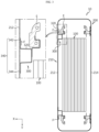
- FIG. 1 is a diagram illustrating a battery pack 10 according to an embodiment of the present disclosure
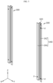
- FIG. 2 is a partially exploded perspective view of the battery pack 10 in FIG. 1
- FIG. 3 is a cross-sectional view taken along line A-A' in FIG. 1 (specifically, FIG. 3 is a cross-sectional view of the battery pack 10 taken along line A-A' on the XY plane in FIG. 1 ).
- FIG. 4 is a cross-sectional view taken along line B-B' in FIG. 1 (specifically, FIG. 4 is a cross-sectional view of the battery pack 10 taken along line B-B' on the XZ plane in FIG. 1 )
- FIG. 5 is a diagram illustrating a venting guidance portion 300 provided in the battery pack 10 in FIG. 1
- FIG. 6 is a diagram illustrating the states before and after thermal runaway of a cell assembly 100 in the battery pack 10 in FIG. 1 .
- FIG. 6(a) is a diagram illustrating the state of the battery pack 10 before thermal runaway of the cell assembly 100
- FIG. 6(b) is a diagram illustrating the state of the battery pack 10 after thermal runaway of the cell assembly 100.
- the battery pack 10 may include a cell assembly 100, a pack frame 200, and a venting guidance portion 300.
- the cell assembly 100 may include at least one battery cell.
- the battery cell may indicate a secondary battery.
- This battery cell may be provided as a pouch-type battery cell, a cylindrical battery cell, or a prismatic battery cell.
- the pack frame 200 may accommodate the cell assembly 100 therein. That is, the pack frame 200 may include an accommodation space for accommodating the cell assembly 100 therein.
- the pack frame 200 may include a material with high heat resistance and rigidity.
- the venting guidance portion 300 may be coupled to the pack frame 200 and configured to cause an outlet S, through which venting gas from the cell assembly 100 is discharged to the outside of the pack frame 200, to be formed.
- an event such as thermal runaway may occur in at least some of the battery cells.
- high-temperature and high-pressure venting gas may be generated inside the battery cell where the thermal event occurred. If the venting gas is randomly discharged from the pack frame accommodating the battery cells, oxygen may flow into the pack frame through a portion of the pack frame where the internal pressure is lowered by the discharge of the venting gas. In this case, fire may be more likely to break out inside the battery pack.
- the venting guidance portion 300 of the present disclosure may be configured such that a coupling portion thereof with the pack frame 200 is at least partially weakened as the internal pressure of the pack frame 200 increases due to the venting gas discharged from the cell assembly 100. Accordingly, if the internal pressure of the pack frame 200 increases due to venting gas, the venting guidance portion 300 may be configured to cause an outlet S, through which the venting gas is discharged to the outside of the pack frame 200, to be formed.
- the venting guidance portion 300 may configure a structurally vulnerable portion at the joint where it is coupled to the pack frame 200, thereby inducing the flow of venting gas to be concentrated on the vulnerable portion if the internal pressure of the pack frame 200 increases due to the venting gas.
- the aforementioned outlet S may be formed in the structurally vulnerable portion when the internal pressure of the pack frame 200 increases due to venting gas. Meanwhile, if high-pressure venting gas is discharged to the outside of the pack frame 200 through the outlet S, oxygen may be prevented from flowing into the pack frame 200 through the outlet S by the discharge pressure of venting gas.
- venting gas it is possible to prevent venting gas from being randomly discharged to the outside of the pack frame 200 by providing a structurally vulnerable portion at the joint where the pack frame 200 and the venting guidance portion 300 are coupled. Accordingly, it is possible to prevent the inflow of oxygen into the pack frame 200, as well as to guide the venting gas to be discharged in a specific direction.
- FIG. 7 is a diagram illustrating a state in which venting gas is discharged from the battery pack 10 in FIG. 1 .
- venting gas is indicated by the reference symbol "V" in FIG. 7 .
- venting guidance portion 300 may be configured to cause the pack frame 200 to open outwards as the internal pressure of the pack frame 200 increases.
- venting guidance portion 300 may configure the vulnerable portion described above to cause an outlet S, through which venting gas is discharged, to be formed in the vulnerable portion when the internal pressure of the pack frame 200 increases due to venting gas.
- the pack frame 200 may open outwards in the vulnerable portion to facilitate the formation of the outlet S for discharging venting gas.
- the pack frame 200 may open outwards to form an outlet S for discharging venting gas, thereby quickly discharging the venting gas through a larger area than a hole-shaped outlet.
- venting guidance portion 300 may be configured such that when the pack frame 200 opens outwards as the internal pressure of the pack frame 200 increases, the space between the cell assembly 100 and the pack frame 200 gradually increases as it is closer to one side.
- the structurally vulnerable portion at the joint where the venting guidance portion 300 is coupled to the pack frame 200 may be located on one side of the pack frame 200 (e.g., the upper side of the pack frame 200).
- the gap between the venting guidance portion 300 and the pack frame 200 may widen on one side of the pack frame 200, so that the outlet S described above may be formed on one side of the pack frame 200.
- the venting guidance portion 300 and the pack frame 200 may remain coupled to each other on the other side of the pack frame 200 (e.g., the lower side of the pack frame 200) where the vulnerable portion is not provided.
- a venting passage P through which venting gas is discharged when the internal pressure of the pack frame 200 increases, may be configured to become wider toward one side of the pack frame 200.
- the venting passage P may be formed to be inclined toward one side thereof, thereby more easily guiding the venting gas to be discharged in a specific direction.
- venting guidance portion 300 may be disposed between the pack frame 200 and the cell assembly 100.
- the stress applied to the pack frame 200 by the discharge pressure of venting gas may be concentrated on the area facing the cell assembly 100.
- the stress is applied to the pack frame 200 due to the discharge pressure of venting gas applied to the pack frame 200, so that the gap between the venting guidance portion 300 and the pack frame 200 may more easily widen in the aforementioned vulnerable portion.
- the outlet S may be easily formed in the pack frame 200 by the discharge pressure of venting gas generated due to thermal runaway of the cell assembly 100.
- the pack frame 200 described above may include side plates 210, an upper plate 220, and a lower plate 230.
- the side plates 210 may constitute the side surfaces of the pack frame 200.
- the venting guidance portion 300 may be coupled to the side plate 210 so as to be disposed between the side plate 210 and the cell assembly 100.
- the stress due to the discharge pressure of venting gas may be concentrated on the side plate 210.
- the side plates 210 may include a front plate 212 and a rear plate 214.
- the rear plate 214 may constitute the rear surface of the pack frame 200.
- the above-described venting guidance portion 300 may be configured to be coupled to the front inner surface of the pack frame 200.
- the venting guidance portion 300 may be coupled to the inner surface of the front plate 212, and the rear plate 214 may be in close contact with the wall of the installation space.
- venting guidance portion 300 may be coupled to the inner surface of the rear plate 214.
- the front plate 212 may be in close contact with the wall of the installation space.
- the upper plate 220 may be configured to cover the top of the cell assembly 100.
- the upper plate 220 may be connected to the upper end of the side plate 210.
- the lower plate 230 may be configured to cover the bottom of the cell assembly 100.
- the lower plate 230 may be connected to the lower end of the side plate 210.
- venting guidance portion 300 may be configured to be located on at least one of both sides of the cell assembly 100 between the pack frame 200 and the cell assembly 100.
- the stress applied to the pack frame 200 by the discharge pressure of venting gas may be concentrated on approximately the entire area of the pack frame 200 facing the cell assembly 100.
- the gap between the venting guidance portion 300 and the pack frame 200 may open in the vulnerable portion of the venting guidance portion 300 located on at least one side of the cell assembly 100 by the discharge pressure of venting gas applied to the pack frame 200.
- the outlet S for discharging venting gas may be configured wider, thereby more quickly discharging the venting gas to the outside.
- the bonding force between one side of the venting guidance portion 300 (e.g., the upper area of the venting guidance portion 300) and the pack frame 200 may be configured to be less than the bonding force between the other side of the venting guidance portion 300 (e.g., the lower area of the venting guidance portion 300) and the pack frame 200.
- the venting guidance portion 300 may be configured to cause an outlet S to be formed between one side of the venting guidance portion 300 and the pack frame 200 as the internal pressure of the pack frame 200 increases.
- the structurally vulnerable portion at the joint where the venting guidance portion 300 is coupled to the pack frame 200 may be located on one side of the venting guidance portion 300.
- the gap between one side of the venting guidance portion 300 and the pack frame 200 may open to form the above-described outlet S on one side of the pack frame 200.
- the coupling between the other side of the venting guidance portion 300 and the pack frame 200 may be maintained.
- the space between the cell assembly 100 and the pack frame 200 may become wider toward one side of the pack frame 200.
- the venting passage P through which venting gas is discharged when the internal pressure of the pack frame 200 increases, may be configured to become wider toward one side of the pack frame 200.
- the venting passage P is configured to be inclined toward one side thereof when the internal pressure of the pack frame 200 increases, the venting gas may be more easily guided to be discharged in a specific direction.
- the venting guidance portion 300 may include a body 320 and a flange 340.
- the body 320 may be coupled to the support E.
- the portion where the body 320 is coupled to the support E may be on the opposite side of the portion where the venting guidance portion 300 is coupled to the inner surface of the pack frame 200. Additionally, the body 320 may be formed to extend long in the vertical direction.
- the flange 340 may extend from both sides of the body 320 and may be coupled to the inner surface of the pack frame 200. In addition, the flange 340 may be formed to extend long in the vertical direction.
- the flange 340 may include a first portion 342 and a second portion 344.
- the second portion 344 may extend from the other side of the body 320.
- the flange 340 may be configured on one side of the venting guidance portion 300 (e.g., the upper area of the venting guidance portion 300) such that the first portion 342 is coupled to the inner surface of the pack frame 200 and such that the second portion 344 is not coupled to the inner surface of the pack frame 200.
- the first portion 342 of the flange 340 may be coupled to the inner surface of the pack frame 200 by a fastening member F (e.g., bolts) on one side of the venting guidance portion 300.
- a fastening member F e.g., bolts
- the flange 340 may be configured on the other side of the venting guidance portion 300 (e.g., the lower area of the venting guidance portion 300) such that both the first portion 342 and the second portion 344 are coupled to the inner surface of the pack frame 200.
- the first portion 342 and the second portion 344 of the flange 340 may be coupled to the inner surface of the pack frame 200 by a fastening member F on the other side of the venting guidance portion 300.
- the structurally vulnerable portion at the joint where the venting guidance portion 300 is coupled to the pack frame 200 may be formed on one side of the venting guidance portion 300 as described above.
- a portion (second portion 344) of the flange 340 is not coupled to the inner surface of the pack frame 200 on one side of the venting guidance portion 300, the gap between one side of the venting guidance portion 300 and the pack frame 200 may open by the discharge pressure of venting gas when the internal pressure of the pack frame 200 increases, thereby forming the outlet S described above on one side of the pack frame 200. Meanwhile, even when the internal pressure of the pack frame 200 increases, the coupling between the other side of the venting guidance portion 300 and the pack frame 200 may be maintained.
- the venting passage P is more easily configured to be inclined toward one side thereof when the internal pressure of the pack frame 200 increases, the venting gas may be more easily guided to be discharged in a specific direction.
- the second portion 344 may be configured to be located closer to the cell assembly 100 than the first portion 342.
- the second portion 344 may be located between the cell assembly 100, which emits venting gas during thermal runaway, and the inner surface of the pack frame 200.
- the discharge pressure of venting gas may be applied to a portion (second portion 344) of the flange 340 that is not coupled to the pack frame 200 on one side of the venting guidance portion 300.
- a portion (first portion 342) of the flange 340 coupled to the inner surface of the pack frame 200 may be disposed farther from the cell assembly 100 than the portion of the flange 340 that is not coupled to the pack frame 200.
- the outlet S may be formed in a portion (second portion 344) where the venting guidance portion 300 and the pack frame 200 are not coupled in the portion where the pack frame 200 faces the cell assembly 100. Accordingly, it is possible to easily form the outlet S for discharging venting gas while preventing the inner surface of the pack frame 200 from being completely separated from the battery pack 10 on one side of the venting guidance portion 300.
- FIG. 8 is an enlarged view of area C in FIG. 2
- FIG. 9 is an enlarged view of area D in FIG. 2 .
- the battery pack 10 may further include a sealing member 400.
- the sealing member 400 may be configured to seal the gap between the top and the side of the pack frame 200 and the gap between the bottom and the side of the pack frame 200.
- the sealing member 400 may be disposed to be spaced apart from the venting guidance portion 300 in the vertical direction in the pack frame 200.
- the sealing member 400 may include a first sealing portion 410 and a second sealing portion 420.
- the first sealing portion 410 may be configured to seal the gap between the side plate 210 and the upper plate 220.
- the first sealing portion 410 may be disposed to be spaced apart from one side of the venting guidance portion 300 (e.g., the upper area of the venting guidance portion 300) in the vertical direction.
- the second sealing portion 420 may be configured to seal the gap between the side plate 210 and the lower plate 230.
- the second sealing portion 420 may be disposed to be spaced apart from the other side of the venting guidance portion 300 (e.g., the lower area of the venting guidance portion 300) in the vertical direction.
- venting gas may be discharged to the outside through the outlet S formed between one side of the venting guidance portion 300 and the pack frame 200.
- the sealing member 400 is disposed to be spaced apart from one side of the venting guidance portion 300 in the vertical direction, the gas may be discharged while being spaced vertically from the outlet S in the case of thermal runaway of the cell assembly 100.
- the pack frame 200 may open outwards, thereby minimizing the discharge of venting gas toward the sealing member 400.
- the discharge of venting gas toward the sealing member 400 may be minimized in the event of thermal runaway of the cell assembly 100. Accordingly, it is possible to minimize damage to the sealing member 400 due to venting gas and minimize the inflow of oxygen through the gap of the pack frame 200.
- FIG. 10 is a diagram illustrating a battery pack 12 according to another embodiment of the present disclosure.
- the battery pack 12 according to the present embodiment is similar to the battery pack 10 in the previous embodiment, redundant descriptions of elements that are substantially the same as or similar to those in the previous embodiment will be omitted, and hereinafter, a description will be made based on the differences from the previous embodiment.
- the pack frame 200 may be configured such that a portion thereof facing the cell assembly 100 is thinner than other portions.
- the portion of the pack frame 200 facing the cell assembly 100 may be configured to be vulnerable. Accordingly, in the event of thermal runaway of the cell assembly 100, the stress due to the discharge pressure of venting gas may act stronger on the thinner portion of the pack frame 200 than on other portions of the pack frame 200.
- the gap between one side of the venting guidance portion 300 and the pack frame 200 may widen more quickly.
- the outlet S may be formed more easily in the pack frame 200 when the internal pressure of the pack frame 200 increases.
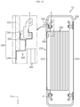
- FIG. 11 is a diagram illustrating a battery pack 14 according to another embodiment of the present disclosure.
- the battery pack 14 according to the present embodiment is similar to the battery pack 10 in the previous embodiment, redundant descriptions of elements that are substantially the same as or similar to those in the previous embodiment will be omitted, and hereinafter, a description will be made based on the differences from the previous embodiment.
- the venting guidance portion 300 may be configured to be coupled to the front inner surface and the rear inner surface of the pack frame 200.
- the battery pack 14 of this embodiment may be configured not to come into close contact with the wall of the installation space.
- the venting guidance portion 300 may be coupled to both the inner surface of the front plate 212 and the inner surface of the rear plate 214 of the side plate 210 as shown in FIG. 11 .
- the outlet S for discharging venting gas may be formed on both the front and rear sides of the battery pack 14 when the internal pressure of the pack frame 200 increases, so the venting gas may be more quickly discharged to the outside of the battery pack 14 in the event of thermal runaway of the cell assembly 100.
- the battery pack 10, 12, or 14 may further include, in addition to the cell assembly 100, various devices for controlling charging and discharging of the cell assembly 100, such as a BMS (Battery Management System), current sensors, fuses, and the like.
- BMS Battery Management System
- current sensors current sensors
- fuses current sensors
- At least one battery pack 10, 12, or 14 according to the present disclosure may be provided as an energy source to form an energy storage system (ESS).
- ESS energy storage system
Landscapes
- Chemical & Material Sciences (AREA)
- Chemical Kinetics & Catalysis (AREA)
- Electrochemistry (AREA)
- General Chemical & Material Sciences (AREA)
- Gas Exhaust Devices For Batteries (AREA)
- Battery Mounting, Suspending (AREA)
Abstract
Description
- The present disclosure relates to a battery pack and an energy storage system including the same, and more specifically, it relates to a battery pack with enhanced stability and an energy storage system including the same.
- The present application claims priority to
Korean Patent Application No. 10-2022-0118128 filed on September 19, 2022 - Recently, the demand for portable electronic products such as laptops, video cameras, and portable phones has rapidly increased, and the development of electric vehicles, energy storage batteries, robots, satellites, and the like has been accelerated, so in line with this, active research on high-performance secondary batteries capable of being repeated charged and discharged is underway.
- Currently commercialized secondary batteries include nickel cadmium batteries, nickel hydrogen batteries, nickel zinc batteries, and lithium secondary batteries. Among these, lithium secondary batteries are in the spotlight for their advantages of free charging and discharging, a very low self-discharge rate, and high energy density as they have almost no memory effect, compared to nickel-based secondary batteries.
- These lithium secondary batteries mainly use lithium-based oxides and carbon materials as positive and negative electrode active materials, respectively. In addition, the lithium secondary batteries include positive and negative electrode plates coated with the positive and negative electrode active materials, respectively, an electrode assembly in which the positive and negative electrode plates are disposed with a separator therebetween, and an exterior case that seals and stores the electrode assembly with an electrolyte.
- Meanwhile, lithium secondary batteries may be classified, depending on the shape of a battery case, into can-type secondary batteries in which the electrode assembly is accommodated in a metal can and pouch-type secondary batteries in which the electrode assembly is accommodated in a pouch of an aluminum laminate sheet. In addition, can-type secondary batteries may be further classified into cylindrical batteries and prismatic batteries depending on the shape of the metal can.
- Here, the pouch of the pouch-type secondary battery may be roughly divided into a lower sheet and an upper sheet covering the same. In this case, the pouch accommodates an electrode assembly obtained by laminating and winding a positive electrode, a negative electrode, and a separator. Then, after storing the electrode assembly, the edges of the upper and lower sheets are sealed by heat fusion or the like. Additionally, an electrode tab extending from each electrode may be coupled to an electrode lead, and an insulating film may be added to the portion where the electrode lead is in contact with the sealing portion.
- As described above, the pouch-type secondary battery may have the flexibility to be configured in various forms. In addition, the pouch-type secondary battery has the advantage of implementing a secondary battery of the same capacity with a smaller volume and mass.
- These lithium secondary batteries are increasingly applied to various fields, such as energy storage systems (ESSs) and the like. The lithium secondary batteries are used as a cell module or battery pack obtained by overlapping or stacking multiple battery cells on each other or in a cartridge into a dense structure to provide high voltage and high current and then electrically connecting the same.
- One of the most important issues in the battery pack configuration is safety. In particular, if a thermal event occurs in any one of a plurality of battery cells included in the battery pack, propagation of the event to other battery cells needs to be suppressed. If thermal propagation between the battery cells is not appropriately suppressed, this may cause thermal events in several battery cells included in the battery pack, resulting in larger problems such as ignition or explosion of the battery pack. Moreover, the ignition or explosion occurring in the battery pack may cause significant damage to people or property in the surrounding area. Therefore, the battery pack requires a configuration capable of appropriately controlling the above-mentioned thermal events.
- Additionally, in the battery pack, high-temperature and high-pressure venting gas may be generated inside the battery cell where a thermal event occurs. If the venting gas is randomly discharged from a pack case of the battery pack accommodating the battery cells, the joint (e.g., where a sealing portion or the like is provided) of the pack case with a low melting point may be damaged first. In this case, oxygen may flow into the pack case through the damaged joints of the plurality of pack cases. In this case, fire is more likely to break out inside the battery pack.
- The present disclosure has been designed to solve the problems of the related art, and therefore the present disclosure is directed to providing a battery pack that is configured to guide venting gas to be discharged in a desired direction when a thermal event occurs, and an energy storage system including the same.
- However, the technical problems that the present disclosure seeks to solve are not limited to the above-mentioned problems, and other problems not mentioned may be clearly understood by those skilled in the art from the description of the invention described below.
- In one aspect of the present disclosure, there is provided a battery pack including a cell assembly, a pack frame configured to accommodate the cell assembly therein, and a venting guidance portion coupled to the pack frame and configured to cause an outlet, through which venting gas emitted from the cell assembly is discharged to the outside of the pack frame, to be formed at a coupling portion with the pack frame, which is at least partially weakened as the internal pressure of the pack frame increases due to the venting gas.
- Preferably, the venting guidance portion may be configured to cause the pack frame to open outwards as the internal pressure of the pack frame increases.
- Preferably, the venting guidance portion may be configured to cause the space between the cell assembly and the pack frame to become wider toward one side thereof when the pack frame opens outwards as the internal pressure of the pack frame increases.
- Preferably, the venting guidance portion may be disposed between the pack frame and the cell assembly.
- Preferably, the venting guidance portion may be configured to be located on at least one of both sides of the cell assembly between the pack frame and the cell assembly.
- Preferably, the bonding force between one side of the venting guidance portion and the pack frame may be configured to be less than the bonding force between the other side of the venting guidance portion and the pack frame, and the venting guidance portion may be configured to cause the outlet to be formed between one side of the venting guidance portion and the pack frame as the internal pressure of the pack frame increases.
- Preferably, the pack frame may further include a support configured to support one side of the venting guidance portion on the opposite side of the inner surface of the pack frame facing the cell assembly.
- Preferably, the venting guidance portion may include a body coupled to the support and a flange extending from both sides of the body and coupled to the inner surface of the pack frame, and the flange may include a first portion extending from one side of the body and a second portion extending from the other side of the body, and the flange on one side of the venting guidance portion may be configured such that the first portion is coupled to the inner surface of the pack frame and such that the second portion is not coupled to the inner surface of the pack frame.
- Preferably, the second portion may be configured to be located closer to the cell assembly than the first portion.
- Preferably, the battery pack may further include a sealing member configured to seal the gap between the top and the side of the pack frame and the gap between the bottom and the side of the pack frame, and the sealing member may be disposed to be spaced apart from the venting guidance portion in the vertical direction in the pack frame.
- Preferably, a portion of the pack frame facing the cell assembly may be thinner than other portions.
- In addition, an energy storage system according to another aspect of the present disclosure includes at least one battery pack according to one aspect of the present disclosure.
- According to an embodiment of the present disclosure, it is possible to prevent venting gas from being randomly discharged to the outside of the pack frame by configuring a structurally vulnerable portion in a portion where the pack frame and the venting guidance portion are coupled. Accordingly, it is possible to prevent oxygen from entering the pack frame, as well as to guide the venting gas to be discharged in a specific direction.
- In addition, according to the embodiment of the present disclosure, since a venting passage is configured to be inclined toward one side when the internal pressure of the pack frame increases, the venting gas may be more easily guided to be discharged in a specific direction.
- Additionally, according to the embodiment of the present disclosure, the discharge of venting gas toward the sealing member may be minimized in the event of thermal runaway of the cell assembly. Accordingly, it is possible to minimize damage to the sealing member due to the venting gas and minimize oxygen inflow through the gap between pack frames.
- In addition, various other additional effects may be obtained by various embodiments of the present disclosure. These various effects of the present disclosure will be explained in detail in respective embodiments, or descriptions of effects that may be easily understood by those skilled in the art will be omitted.
- The accompanying drawings illustrate a preferred embodiment of the present disclosure and, together with the detailed description of the invention, serve to provide further understanding of the technical idea of the present disclosure, and thus, the present disclosure is not construed as being limited to the drawings.
-
FIG. 1 is a diagram illustrating a battery pack according to an embodiment of the present disclosure. -
FIG. 2 is a partially exploded perspective view of the battery pack inFIG. 1 . -
FIG. 3 is a cross-sectional view taken along line A-A' inFIG. 1 . -
FIG. 4 is a cross-sectional view taken along line B-B' inFIG. 1 . -
FIG. 5 is a diagram illustrating a venting guidance portion provided in the battery pack inFIG. 1 . -
FIG. 6 is a diagram illustrating the states before and after thermal runaway of a cell assembly in the battery pack inFIG. 1 . -
FIG. 7 is a diagram illustrating a state in which venting gas is discharged from the battery pack inFIG. 1 . -
FIG. 8 is an enlarged view of area C inFIG. 2 . -
FIG. 9 is an enlarged view of area D inFIG. 2 . -
FIG. 10 is a diagram illustrating a battery pack according to another embodiment of the present disclosure. -
FIG. 11 is a diagram illustrating a battery pack according to another embodiment of - Hereinafter, preferred embodiments of the present disclosure will be described in detail with reference to the accompanying drawings. Prior to the description, it should be understood that the terms used in the specification and the appended claims should not be construed as limited to general and dictionary meanings, but interpreted based on the meanings and concepts corresponding to technical aspects of the present disclosure on the basis of the principle that the inventor is allowed to define terms appropriately for the best explanation.
- Therefore, the configuration proposed in the embodiments and drawings of this specification is only the most preferable embodiment of the present disclosure and does not represent all technical ideas of the present disclosure, so it should be understood that various equivalents and modifications could be made thereto at the time of filing the application.
-
FIG. 1 is a diagram illustrating abattery pack 10 according to an embodiment of the present disclosure,FIG. 2 is a partially exploded perspective view of thebattery pack 10 inFIG. 1 , andFIG. 3 is a cross-sectional view taken along line A-A' inFIG. 1 (specifically,FIG. 3 is a cross-sectional view of thebattery pack 10 taken along line A-A' on the XY plane inFIG. 1 ). - In addition,
FIG. 4 is a cross-sectional view taken along line B-B' inFIG. 1 (specifically,FIG. 4 is a cross-sectional view of thebattery pack 10 taken along line B-B' on the XZ plane inFIG. 1 ),FIG. 5 is a diagram illustrating a ventingguidance portion 300 provided in thebattery pack 10 inFIG. 1 , andFIG. 6 is a diagram illustrating the states before and after thermal runaway of acell assembly 100 in thebattery pack 10 inFIG. 1 . Here, inFIG. 6, FIG. 6(a) is a diagram illustrating the state of thebattery pack 10 before thermal runaway of thecell assembly 100, andFIG. 6(b) is a diagram illustrating the state of thebattery pack 10 after thermal runaway of thecell assembly 100. - In the embodiment of the present disclosure, the X-axis direction shown in the drawing may indicate the front/back direction of the
battery pack 10, the Y-axis direction may indicate the left/right direction of thebattery pack 10, which is perpendicular to the X-axis direction on the horizontal plane (XY plane), and the Z-axis direction may indicate the up/down direction perpendicular to both the X-axis direction and the Y-axis direction. - Referring to
FIGS. 1 to 6 , thebattery pack 10 according to an embodiment of the present disclosure may include acell assembly 100, apack frame 200, and a ventingguidance portion 300. - The
cell assembly 100 may include at least one battery cell. Here, the battery cell may indicate a secondary battery. This battery cell may be provided as a pouch-type battery cell, a cylindrical battery cell, or a prismatic battery cell. - The
pack frame 200 may accommodate thecell assembly 100 therein. That is, thepack frame 200 may include an accommodation space for accommodating thecell assembly 100 therein. For example, thepack frame 200 may include a material with high heat resistance and rigidity. - The venting
guidance portion 300 may be coupled to thepack frame 200 and configured to cause an outlet S, through which venting gas from thecell assembly 100 is discharged to the outside of thepack frame 200, to be formed. - In a typical battery pack, an event such as thermal runaway may occur in at least some of the battery cells. In this case, high-temperature and high-pressure venting gas may be generated inside the battery cell where the thermal event occurred. If the venting gas is randomly discharged from the pack frame accommodating the battery cells, oxygen may flow into the pack frame through a portion of the pack frame where the internal pressure is lowered by the discharge of the venting gas. In this case, fire may be more likely to break out inside the battery pack.
- To solve this problem, the venting
guidance portion 300 of the present disclosure may be configured such that a coupling portion thereof with thepack frame 200 is at least partially weakened as the internal pressure of thepack frame 200 increases due to the venting gas discharged from thecell assembly 100. Accordingly, if the internal pressure of thepack frame 200 increases due to venting gas, the ventingguidance portion 300 may be configured to cause an outlet S, through which the venting gas is discharged to the outside of thepack frame 200, to be formed. - That is, the venting
guidance portion 300 may configure a structurally vulnerable portion at the joint where it is coupled to thepack frame 200, thereby inducing the flow of venting gas to be concentrated on the vulnerable portion if the internal pressure of thepack frame 200 increases due to the venting gas. In this case, the aforementioned outlet S may be formed in the structurally vulnerable portion when the internal pressure of thepack frame 200 increases due to venting gas. Meanwhile, if high-pressure venting gas is discharged to the outside of thepack frame 200 through the outlet S, oxygen may be prevented from flowing into thepack frame 200 through the outlet S by the discharge pressure of venting gas. - According to this embodiment of the present disclosure, it is possible to prevent venting gas from being randomly discharged to the outside of the
pack frame 200 by providing a structurally vulnerable portion at the joint where thepack frame 200 and the ventingguidance portion 300 are coupled. Accordingly, it is possible to prevent the inflow of oxygen into thepack frame 200, as well as to guide the venting gas to be discharged in a specific direction. -
FIG. 7 is a diagram illustrating a state in which venting gas is discharged from thebattery pack 10 inFIG. 1 . Here, venting gas is indicated by the reference symbol "V" inFIG. 7 . - Referring to
FIG. 7 , the ventingguidance portion 300 may be configured to cause thepack frame 200 to open outwards as the internal pressure of thepack frame 200 increases. - For example, the venting
guidance portion 300 may configure the vulnerable portion described above to cause an outlet S, through which venting gas is discharged, to be formed in the vulnerable portion when the internal pressure of thepack frame 200 increases due to venting gas. In this case, thepack frame 200 may open outwards in the vulnerable portion to facilitate the formation of the outlet S for discharging venting gas. - According to this embodiment, when the internal pressure of the
pack frame 200 increases, thepack frame 200 may open outwards to form an outlet S for discharging venting gas, thereby quickly discharging the venting gas through a larger area than a hole-shaped outlet. - In particular, the venting
guidance portion 300 may be configured such that when thepack frame 200 opens outwards as the internal pressure of thepack frame 200 increases, the space between thecell assembly 100 and thepack frame 200 gradually increases as it is closer to one side. - For example, the structurally vulnerable portion at the joint where the venting
guidance portion 300 is coupled to thepack frame 200 may be located on one side of the pack frame 200 (e.g., the upper side of the pack frame 200). In this case, if the internal pressure of thepack frame 200 increases, the gap between the ventingguidance portion 300 and thepack frame 200 may widen on one side of thepack frame 200, so that the outlet S described above may be formed on one side of thepack frame 200. On the other hand, the ventingguidance portion 300 and thepack frame 200 may remain coupled to each other on the other side of the pack frame 200 (e.g., the lower side of the pack frame 200) where the vulnerable portion is not provided. - Accordingly, the space between the
cell assembly 100 and thepack frame 200 may become wider toward one side of thepack frame 200. In other words, a venting passage P, through which venting gas is discharged when the internal pressure of thepack frame 200 increases, may be configured to become wider toward one side of thepack frame 200. - According to this embodiment, if the internal pressure of the
pack frame 200 increases, the venting passage P may be formed to be inclined toward one side thereof, thereby more easily guiding the venting gas to be discharged in a specific direction. - Referring back to
FIGS. 2 to 6 , the ventingguidance portion 300 may be disposed between thepack frame 200 and thecell assembly 100. - Accordingly, the stress applied to the
pack frame 200 by the discharge pressure of venting gas may be concentrated on the area facing thecell assembly 100. In this case, the stress is applied to thepack frame 200 due to the discharge pressure of venting gas applied to thepack frame 200, so that the gap between the ventingguidance portion 300 and thepack frame 200 may more easily widen in the aforementioned vulnerable portion. - According to this embodiment, the outlet S may be easily formed in the
pack frame 200 by the discharge pressure of venting gas generated due to thermal runaway of thecell assembly 100. - Meanwhile, the
pack frame 200 described above may includeside plates 210, anupper plate 220, and alower plate 230. - The
side plates 210 may constitute the side surfaces of thepack frame 200. In this case, the ventingguidance portion 300 may be coupled to theside plate 210 so as to be disposed between theside plate 210 and thecell assembly 100. In this case, the stress due to the discharge pressure of venting gas may be concentrated on theside plate 210. - Specifically, the
side plates 210 may include afront plate 212 and arear plate 214. - The
front plate 212 may constitute the front surface of thepack frame 200. - The
rear plate 214 may constitute the rear surface of thepack frame 200. - According to the embodiment of the present disclosure, in the case where the
battery pack 10 is in close contact with the wall in the installation space depending on the installation environment, the above-describedventing guidance portion 300 may be configured to be coupled to the front inner surface of thepack frame 200. For example, as shown inFIGS. 2 to 7 , the ventingguidance portion 300 may be coupled to the inner surface of thefront plate 212, and therear plate 214 may be in close contact with the wall of the installation space. - Meanwhile, although not shown, the above-described
venting guidance portion 300 may be coupled to the inner surface of therear plate 214. In this case, thefront plate 212 may be in close contact with the wall of the installation space. - The
upper plate 220 may be configured to cover the top of thecell assembly 100. Theupper plate 220 may be connected to the upper end of theside plate 210. - The
lower plate 230 may be configured to cover the bottom of thecell assembly 100. Thelower plate 230 may be connected to the lower end of theside plate 210. - In particular, the venting
guidance portion 300 may be configured to be located on at least one of both sides of thecell assembly 100 between thepack frame 200 and thecell assembly 100. - Accordingly, the stress applied to the
pack frame 200 by the discharge pressure of venting gas may be concentrated on approximately the entire area of thepack frame 200 facing thecell assembly 100. - In this case, the gap between the venting
guidance portion 300 and thepack frame 200 may open in the vulnerable portion of the ventingguidance portion 300 located on at least one side of thecell assembly 100 by the discharge pressure of venting gas applied to thepack frame 200. - According to this embodiment, when the internal pressure of the
pack frame 200 increases, the outlet S for discharging venting gas may be configured wider, thereby more quickly discharging the venting gas to the outside. - Referring again to
FIGS. 2 to 7 , the bonding force between one side of the venting guidance portion 300 (e.g., the upper area of the venting guidance portion 300) and thepack frame 200 may be configured to be less than the bonding force between the other side of the venting guidance portion 300 (e.g., the lower area of the venting guidance portion 300) and thepack frame 200. In addition, the ventingguidance portion 300 may be configured to cause an outlet S to be formed between one side of the ventingguidance portion 300 and thepack frame 200 as the internal pressure of thepack frame 200 increases. - That is, the structurally vulnerable portion at the joint where the venting
guidance portion 300 is coupled to thepack frame 200 may be located on one side of the ventingguidance portion 300. In this case, when the internal pressure of thepack frame 200 increases, the gap between one side of the ventingguidance portion 300 and thepack frame 200 may open to form the above-described outlet S on one side of thepack frame 200. Meanwhile, even if the internal pressure of thepack frame 200 increases, the coupling between the other side of the ventingguidance portion 300 and thepack frame 200 may be maintained. - Accordingly, the space between the
cell assembly 100 and thepack frame 200 may become wider toward one side of thepack frame 200. In other words, the venting passage P, through which venting gas is discharged when the internal pressure of thepack frame 200 increases, may be configured to become wider toward one side of thepack frame 200. - According to this embodiment, since the venting passage P is configured to be inclined toward one side thereof when the internal pressure of the
pack frame 200 increases, the venting gas may be more easily guided to be discharged in a specific direction. - In particular, the
pack frame 200 may further include a support E. - The support E may be configured to support one side of the venting
guidance portion 300 on the opposite side of the inner surface of thepack frame 200 facing thecell assembly 100. For example, the support E and the ventingguidance portion 300 may be coupled by bolting, etc., but the coupling is not limited thereto. Additionally, the support E may connect the above-describedupper plate 220 andlower plate 230. - That is, since one side of the venting guidance portion 300 (the side of the venting
guidance portion 300 opposite the portion coupled to the inner surface of the pack frame 200) is stably supported by the support E, the gap between one side of the ventingguidance portion 300 and thepack frame 200 may more easily widen by the discharge pressure of venting gas when the internal pressure of thepack frame 200 increases. - According to this embodiment, the outlet S may be formed more easily in the
pack frame 200 by the discharge pressure of venting gas generated due to thermal runaway of thecell assembly 100. - Hereinafter, the venting
guidance portion 300 will be described in more detail. - Referring back to
FIGS. 2 to 7 , the ventingguidance portion 300 may include abody 320 and aflange 340. - The
body 320 may be coupled to the support E. The portion where thebody 320 is coupled to the support E may be on the opposite side of the portion where the ventingguidance portion 300 is coupled to the inner surface of thepack frame 200. Additionally, thebody 320 may be formed to extend long in the vertical direction. - The
flange 340 may extend from both sides of thebody 320 and may be coupled to the inner surface of thepack frame 200. In addition, theflange 340 may be formed to extend long in the vertical direction. - The
flange 340 may include afirst portion 342 and asecond portion 344. - The
first portion 342 may extend from one side of thebody 320. - The
second portion 344 may extend from the other side of thebody 320. - In this case, the
flange 340 may be configured on one side of the venting guidance portion 300 (e.g., the upper area of the venting guidance portion 300) such that thefirst portion 342 is coupled to the inner surface of thepack frame 200 and such that thesecond portion 344 is not coupled to the inner surface of thepack frame 200. For example, thefirst portion 342 of theflange 340 may be coupled to the inner surface of thepack frame 200 by a fastening member F (e.g., bolts) on one side of the ventingguidance portion 300. - Meanwhile, the
flange 340 may be configured on the other side of the venting guidance portion 300 (e.g., the lower area of the venting guidance portion 300) such that both thefirst portion 342 and thesecond portion 344 are coupled to the inner surface of thepack frame 200. For example, thefirst portion 342 and thesecond portion 344 of theflange 340 may be coupled to the inner surface of thepack frame 200 by a fastening member F on the other side of the ventingguidance portion 300. - In this case, the structurally vulnerable portion at the joint where the venting
guidance portion 300 is coupled to thepack frame 200 may be formed on one side of the ventingguidance portion 300 as described above. Specifically, since a portion (second portion 344) of theflange 340 is not coupled to the inner surface of thepack frame 200 on one side of the ventingguidance portion 300, the gap between one side of the ventingguidance portion 300 and thepack frame 200 may open by the discharge pressure of venting gas when the internal pressure of thepack frame 200 increases, thereby forming the outlet S described above on one side of thepack frame 200. Meanwhile, even when the internal pressure of thepack frame 200 increases, the coupling between the other side of the ventingguidance portion 300 and thepack frame 200 may be maintained. - According to this embodiment, since the venting passage P is more easily configured to be inclined toward one side thereof when the internal pressure of the
pack frame 200 increases, the venting gas may be more easily guided to be discharged in a specific direction. - In particular, the
second portion 344 may be configured to be located closer to thecell assembly 100 than thefirst portion 342. - Specifically, the
second portion 344 may be located between thecell assembly 100, which emits venting gas during thermal runaway, and the inner surface of thepack frame 200. - That is, the discharge pressure of venting gas may be applied to a portion (second portion 344) of the
flange 340 that is not coupled to thepack frame 200 on one side of the ventingguidance portion 300. In addition, on one side of the ventingguidance portion 300, a portion (first portion 342) of theflange 340 coupled to the inner surface of thepack frame 200 may be disposed farther from thecell assembly 100 than the portion of theflange 340 that is not coupled to thepack frame 200. - According to this embodiment, on one side of the venting
guidance portion 300, while a portion (first portion 342) of the ventingguidance portion 300 partially maintains the coupling between the ventingguidance portion 300 and thepack frame 200, the outlet S may be formed in a portion (second portion 344) where the ventingguidance portion 300 and thepack frame 200 are not coupled in the portion where thepack frame 200 faces thecell assembly 100. Accordingly, it is possible to easily form the outlet S for discharging venting gas while preventing the inner surface of thepack frame 200 from being completely separated from thebattery pack 10 on one side of the ventingguidance portion 300. -
FIG. 8 is an enlarged view of area C inFIG. 2 , andFIG. 9 is an enlarged view of area D inFIG. 2 . - Referring to
FIGS. 2 ,4 , and6 to 9 , thebattery pack 10 may further include a sealingmember 400. - The sealing
member 400 may be configured to seal the gap between the top and the side of thepack frame 200 and the gap between the bottom and the side of thepack frame 200. - In this case, the sealing
member 400 may be disposed to be spaced apart from the ventingguidance portion 300 in the vertical direction in thepack frame 200. - In an embodiment, the sealing
member 400 may include afirst sealing portion 410 and asecond sealing portion 420. - The
first sealing portion 410 may be configured to seal the gap between theside plate 210 and theupper plate 220. For example, thefirst sealing portion 410 may be disposed to be spaced apart from one side of the venting guidance portion 300 (e.g., the upper area of the venting guidance portion 300) in the vertical direction. - The
second sealing portion 420 may be configured to seal the gap between theside plate 210 and thelower plate 230. For example, thesecond sealing portion 420 may be disposed to be spaced apart from the other side of the venting guidance portion 300 (e.g., the lower area of the venting guidance portion 300) in the vertical direction. - Meanwhile, during thermal runaway of the
cell assembly 100, venting gas may be discharged to the outside through the outlet S formed between one side of the ventingguidance portion 300 and thepack frame 200. At this time, since the sealingmember 400 is disposed to be spaced apart from one side of the ventingguidance portion 300 in the vertical direction, the gas may be discharged while being spaced vertically from the outlet S in the case of thermal runaway of thecell assembly 100. In particular, when the internal pressure of thecell assembly 100 increases, thepack frame 200 may open outwards, thereby minimizing the discharge of venting gas toward the sealingmember 400. - According to this embodiment, the discharge of venting gas toward the sealing
member 400 may be minimized in the event of thermal runaway of thecell assembly 100. Accordingly, it is possible to minimize damage to the sealingmember 400 due to venting gas and minimize the inflow of oxygen through the gap of thepack frame 200. -
FIG. 10 is a diagram illustrating abattery pack 12 according to another embodiment of the present disclosure. - Since the
battery pack 12 according to the present embodiment is similar to thebattery pack 10 in the previous embodiment, redundant descriptions of elements that are substantially the same as or similar to those in the previous embodiment will be omitted, and hereinafter, a description will be made based on the differences from the previous embodiment. - Referring to
FIG. 10 , in thebattery pack 12, thepack frame 200 may be configured such that a portion thereof facing thecell assembly 100 is thinner than other portions. - That is, in the
battery pack 12 of this embodiment, the portion of thepack frame 200 facing thecell assembly 100 may be configured to be vulnerable. Accordingly, in the event of thermal runaway of thecell assembly 100, the stress due to the discharge pressure of venting gas may act stronger on the thinner portion of thepack frame 200 than on other portions of thepack frame 200. - Accordingly, when the internal pressure of the
pack frame 200 increases, the gap between one side of the ventingguidance portion 300 and thepack frame 200 may widen more quickly. - According to the
battery pack 12 of this embodiment, the outlet S may be formed more easily in thepack frame 200 when the internal pressure of thepack frame 200 increases. -
FIG. 11 is a diagram illustrating abattery pack 14 according to another embodiment of the present disclosure. - Since the
battery pack 14 according to the present embodiment is similar to thebattery pack 10 in the previous embodiment, redundant descriptions of elements that are substantially the same as or similar to those in the previous embodiment will be omitted, and hereinafter, a description will be made based on the differences from the previous embodiment. - Referring to
FIG. 11 , in thebattery pack 14, the ventingguidance portion 300 may be configured to be coupled to the front inner surface and the rear inner surface of thepack frame 200. - The
battery pack 14 of this embodiment may be configured not to come into close contact with the wall of the installation space. Specifically, the ventingguidance portion 300 may be coupled to both the inner surface of thefront plate 212 and the inner surface of therear plate 214 of theside plate 210 as shown inFIG. 11 . - According to the
battery pack 14 of this embodiment, the outlet S for discharging venting gas may be formed on both the front and rear sides of thebattery pack 14 when the internal pressure of thepack frame 200 increases, so the venting gas may be more quickly discharged to the outside of thebattery pack 14 in the event of thermal runaway of thecell assembly 100. - Meanwhile, the
battery pack cell assembly 100, various devices for controlling charging and discharging of thecell assembly 100, such as a BMS (Battery Management System), current sensors, fuses, and the like. - In addition, at least one
battery pack - As described above, although the present disclosure has been described according to specific embodiments and drawings, the present disclosure is not limited thereto, and it is obvious to those skilled in the art to which the present disclosure pertains that various modifications and variations are able to be derived within the technical idea of the present disclosure and the scope of the claims described below.
- Meanwhile, although terms indicating directions such as up, down, left, right, front, and back are used in this specification, it is obvious to those skilled in the art that these terms are only for convenience of explanation and may vary depending on the location of the target object or the location of the observer.
-
- 10, 12, 14: Battery pack
- 100: Cell assembly
- 200: Pack frame
- E: Support
- 300: Venting guidance portion
- 320: Body
- 340: Flange
- 342: First portion
- 344: Second portion
- S: Outlet
- 400: Sealing member
Claims (12)
- A battery pack comprisinga cell assembly;a pack frame configured to accommodate the cell assembly therein; anda venting guidance portion coupled to the pack frame and configured to cause an outlet, through which venting gas emitted from the cell assembly is discharged to the outside of the pack frame, to be formed at a coupling portion with the pack frame, which is at least partially weakened as the internal pressure of the pack frame increases due to the venting gas.
- The battery pack according to claim 1,
wherein the venting guidance portion is configured to cause the pack frame to open outwards as the internal pressure of the pack frame increases. - The battery pack according to claim 2,
wherein the venting guidance portion is configured to cause the space between the cell assembly and the pack frame to become wider toward one side thereof when the pack frame opens outwards as the internal pressure of the pack frame increases. - The battery pack according to claim .1,
wherein the venting guidance portion is disposed between the pack frame and the cell assembly. - The battery pack according to claim 4,
wherein the venting guidance portion is configured to be located on at least one of both sides of the cell assembly between the pack frame and the cell assembly. - The battery pack according to claim 1,wherein the bonding force between one side of the venting guidance portion and the pack frame is configured to be less than the bonding force between the other side of the venting guidance portion and the pack frame, andwherein the venting guidance portion is configured to cause the outlet to be formed between one side of the venting guidance portion and the pack frame as the internal pressure of the pack frame increases.
- The battery pack according to claim 6,wherein the pack frame further comprisesa support configured to support one side of the venting guidance portion on the opposite side of the inner surface of the pack frame facing the cell assembly.
- The battery pack according to claim 7,
wherein the venting guidance portion comprises:a body coupled to the support; anda flange extending from both sides of the body and coupled to the inner surface of the pack frame,wherein the flange comprises:a first portion extending from one side of the body; anda second portion extending from the other side of the body, andwherein the flange on one side of the venting guidance portion is configured such that the first portion is coupled to the inner surface of the pack frame and such that the second portion is not coupled to the inner surface of the pack frame. - The battery pack according to claim 8,
wherein the second portion is configured to be located closer to the cell assembly than the first portion. - The battery pack according to claim 1,further comprising a sealing member configured to seal the gap between the top and the side of the pack frame and the gap between the bottom and the side of the pack frame,wherein the sealing member is disposed to be spaced apart from the venting guidance portion in the vertical direction in the pack frame.
- The battery pack according to claim 1,
wherein a portion of the pack frame facing the cell assembly is thinner than other portions. - An energy storage system comprising at least one battery pack according to any one of claims 1 to 11.
Priority Applications (1)
| Application Number | Priority Date | Filing Date | Title |
|---|---|---|---|
| EP26150585.3A EP4708497A2 (en) | 2022-09-19 | 2023-09-18 | Battery pack and energy storage system including same |
Applications Claiming Priority (2)
| Application Number | Priority Date | Filing Date | Title |
|---|---|---|---|
| KR1020220118128A KR20240039485A (en) | 2022-09-19 | 2022-09-19 | Battery pack and energy storage system including the same |
| PCT/KR2023/014092 WO2024063485A1 (en) | 2022-09-19 | 2023-09-18 | Battery pack, and energy storage system including same |
Related Child Applications (1)
| Application Number | Title | Priority Date | Filing Date |
|---|---|---|---|
| EP26150585.3A Division EP4708497A2 (en) | 2022-09-19 | 2023-09-18 | Battery pack and energy storage system including same |
Publications (2)
| Publication Number | Publication Date |
|---|---|
| EP4576375A1 true EP4576375A1 (en) | 2025-06-25 |
| EP4576375A4 EP4576375A4 (en) | 2026-03-11 |
Family
ID=90454956
Family Applications (2)
| Application Number | Title | Priority Date | Filing Date |
|---|---|---|---|
| EP26150585.3A Pending EP4708497A2 (en) | 2022-09-19 | 2023-09-18 | Battery pack and energy storage system including same |
| EP23868537.4A Pending EP4576375A4 (en) | 2022-09-19 | 2023-09-18 | BATTERY PACK AND ENERGY STORAGE SYSTEM WITH THIS |
Family Applications Before (1)
| Application Number | Title | Priority Date | Filing Date |
|---|---|---|---|
| EP26150585.3A Pending EP4708497A2 (en) | 2022-09-19 | 2023-09-18 | Battery pack and energy storage system including same |
Country Status (6)
| Country | Link |
|---|---|
| US (1) | US20250062483A1 (en) |
| EP (2) | EP4708497A2 (en) |
| JP (1) | JP7809819B2 (en) |
| KR (1) | KR20240039485A (en) |
| CN (1) | CN118355554A (en) |
| WO (1) | WO2024063485A1 (en) |
Family Cites Families (16)
| Publication number | Priority date | Publication date | Assignee | Title |
|---|---|---|---|---|
| JP5440790B2 (en) * | 2010-03-18 | 2014-03-12 | 三菱自動車工業株式会社 | Battery case and battery pack |
| JP5619154B2 (en) * | 2010-11-30 | 2014-11-05 | パナソニック株式会社 | Battery pack |
| JP6089267B2 (en) * | 2012-03-16 | 2017-03-08 | パナソニックIpマネジメント株式会社 | Power storage device |
| JP5850039B2 (en) * | 2013-12-26 | 2016-02-03 | 株式会社豊田自動織機 | Battery pack |
| DE102014006343A1 (en) * | 2014-04-30 | 2015-11-05 | Daimler Ag | Battery housing for a motor vehicle battery |
| JP6606907B2 (en) * | 2015-07-30 | 2019-11-20 | 株式会社Gsユアサ | Power storage device |
| JP6690451B2 (en) * | 2016-07-20 | 2020-04-28 | 株式会社豊田自動織機 | Battery pack |
| JP2018067481A (en) * | 2016-10-20 | 2018-04-26 | 株式会社豊田自動織機 | Battery pack |
| JP6996272B2 (en) * | 2017-12-13 | 2022-01-17 | 日産自動車株式会社 | Battery pack |
| DE102019200156A1 (en) * | 2019-01-09 | 2020-07-09 | Robert Bosch Gmbh | Battery system |
| CN111192989A (en) * | 2020-01-08 | 2020-05-22 | 深圳市欣旺达综合能源服务有限公司 | Battery compartment pressure relief device and battery compartment |
| JP7731345B2 (en) * | 2020-03-31 | 2025-08-29 | 三洋電機株式会社 | Power supply device, vehicle equipped with same, and power storage device |
| KR102943955B1 (en) * | 2020-10-13 | 2026-03-24 | 주식회사 엘지에너지솔루션 | ESS battery pack with a gas discharge structure |
| DE102021000684A1 (en) * | 2021-02-10 | 2021-03-25 | Daimler Ag | Energy storage device for a motor vehicle, in particular for a motor vehicle |
| KR102503250B1 (en) | 2021-02-18 | 2023-02-23 | 신성민 | Nail sticker and method for manufacturing the same |
| CN217158332U (en) * | 2022-03-21 | 2022-08-09 | 湖北亿纬动力有限公司 | Battery box |
-
2022
- 2022-09-19 KR KR1020220118128A patent/KR20240039485A/en not_active Ceased
-
2023
- 2023-09-18 CN CN202380015145.6A patent/CN118355554A/en active Pending
- 2023-09-18 EP EP26150585.3A patent/EP4708497A2/en active Pending
- 2023-09-18 US US18/724,912 patent/US20250062483A1/en active Pending
- 2023-09-18 WO PCT/KR2023/014092 patent/WO2024063485A1/en not_active Ceased
- 2023-09-18 EP EP23868537.4A patent/EP4576375A4/en active Pending
- 2023-09-18 JP JP2024541241A patent/JP7809819B2/en active Active
Also Published As
| Publication number | Publication date |
|---|---|
| JP2025502137A (en) | 2025-01-24 |
| EP4708497A2 (en) | 2026-03-11 |
| KR20240039485A (en) | 2024-03-26 |
| CN118355554A (en) | 2024-07-16 |
| WO2024063485A1 (en) | 2024-03-28 |
| EP4576375A4 (en) | 2026-03-11 |
| US20250062483A1 (en) | 2025-02-20 |
| JP7809819B2 (en) | 2026-02-02 |
Similar Documents
| Publication | Publication Date | Title |
|---|---|---|
| EP4057434B1 (en) | Battery module, battery pack comprising same, and automobile | |
| US20230207956A1 (en) | Battery Cell, And Battery Module, Battery Pack And Vehicle Including The Same | |
| KR20230091784A (en) | Battery module with improved safety | |
| EP4404361A1 (en) | Battery pack and device including same | |
| EP4358265A1 (en) | Battery module, battery pack, and vehicle including same | |
| EP4325647A1 (en) | Battery module, battery pack, and vehicle comprising same | |
| KR20230097968A (en) | Battery cell, battery module, battery pack and vehicle including the same | |
| EP4386960A1 (en) | Battery pack and vehicle comprising same | |
| KR20240051647A (en) | Battery pack and vehicle including the same | |
| EP4216354B1 (en) | Battery module, battery pack, and vehicle including the same | |
| EP4539227A1 (en) | Battery pack and device including the same | |
| EP4708497A2 (en) | Battery pack and energy storage system including same | |
| EP4456288A1 (en) | Battery pack and energy storage system including same | |
| EP4345994A1 (en) | Battery module, battery pack and vehicle including same | |
| EP4539233A1 (en) | Battery pack and vehicle including same | |
| EP4425677A1 (en) | Battery pack and device including same | |
| EP4579939A1 (en) | Battery module | |
| EP4629423A1 (en) | Battery pack | |
| EP4712246A1 (en) | Battery pack and device including same | |
| CN117355984A (en) | Battery cells, battery modules including the battery cells, battery packs and vehicles |
Legal Events
| Date | Code | Title | Description |
|---|---|---|---|
| STAA | Information on the status of an ep patent application or granted ep patent |
Free format text: STATUS: THE INTERNATIONAL PUBLICATION HAS BEEN MADE |
|
| PUAI | Public reference made under article 153(3) epc to a published international application that has entered the european phase |
Free format text: ORIGINAL CODE: 0009012 |
|
| STAA | Information on the status of an ep patent application or granted ep patent |
Free format text: STATUS: REQUEST FOR EXAMINATION WAS MADE |
|
| 17P | Request for examination filed |
Effective date: 20250320 |
|
| AK | Designated contracting states |
Kind code of ref document: A1 Designated state(s): AL AT BE BG CH CY CZ DE DK EE ES FI FR GB GR HR HU IE IS IT LI LT LU LV MC ME MK MT NL NO PL PT RO RS SE SI SK SM TR |
|
| DAV | Request for validation of the european patent (deleted) | ||
| DAX | Request for extension of the european patent (deleted) | ||
| A4 | Supplementary search report drawn up and despatched |
Effective date: 20260211 |
|
| RIC1 | Information provided on ipc code assigned before grant |
Ipc: H01M 50/342 20210101AFI20260205BHEP Ipc: H01M 50/24 20210101ALI20260205BHEP Ipc: H01M 50/209 20210101ALI20260205BHEP Ipc: H01M 50/233 20210101ALI20260205BHEP Ipc: H01M 50/367 20210101ALI20260205BHEP |