EP4576291A1 - Verfahren zur herstellung einer elektrochemischen zelle mit gleitwerkzeugen - Google Patents
Verfahren zur herstellung einer elektrochemischen zelle mit gleitwerkzeugen Download PDFInfo
- Publication number
- EP4576291A1 EP4576291A1 EP23307239.6A EP23307239A EP4576291A1 EP 4576291 A1 EP4576291 A1 EP 4576291A1 EP 23307239 A EP23307239 A EP 23307239A EP 4576291 A1 EP4576291 A1 EP 4576291A1
- Authority
- EP
- European Patent Office
- Prior art keywords
- electrode
- supporting
- pivoting
- assembly
- tool
- Prior art date
- Legal status (The legal status is an assumption and is not a legal conclusion. Google has not performed a legal analysis and makes no representation as to the accuracy of the status listed.)
- Pending
Links
Images


Classifications
-
- B—PERFORMING OPERATIONS; TRANSPORTING
- B23—MACHINE TOOLS; METAL-WORKING NOT OTHERWISE PROVIDED FOR
- B23K—SOLDERING OR UNSOLDERING; WELDING; CLADDING OR PLATING BY SOLDERING OR WELDING; CUTTING BY APPLYING HEAT LOCALLY, e.g. FLAME CUTTING; WORKING BY LASER BEAM
- B23K37/00—Auxiliary devices or processes, not specially adapted for a procedure covered by only one of the other main groups of this subclass
- B23K37/04—Auxiliary devices or processes, not specially adapted for a procedure covered by only one of the other main groups of this subclass for holding or positioning work
- B23K37/0426—Fixtures for other work
- B23K37/0435—Clamps
- B23K37/0443—Jigs
-
- H—ELECTRICITY
- H01—ELECTRIC ELEMENTS
- H01M—PROCESSES OR MEANS, e.g. BATTERIES, FOR THE DIRECT CONVERSION OF CHEMICAL ENERGY INTO ELECTRICAL ENERGY
- H01M10/00—Secondary cells; Manufacture thereof
- H01M10/04—Construction or manufacture in general
- H01M10/0404—Machines for assembling batteries
-
- H—ELECTRICITY
- H01—ELECTRIC ELEMENTS
- H01M—PROCESSES OR MEANS, e.g. BATTERIES, FOR THE DIRECT CONVERSION OF CHEMICAL ENERGY INTO ELECTRICAL ENERGY
- H01M50/00—Constructional details or processes of manufacture of the non-active parts of electrochemical cells other than fuel cells, e.g. hybrid cells
- H01M50/10—Primary casings; Jackets or wrappings
- H01M50/102—Primary casings; Jackets or wrappings characterised by their shape or physical structure
- H01M50/103—Primary casings; Jackets or wrappings characterised by their shape or physical structure prismatic or rectangular
-
- H—ELECTRICITY
- H01—ELECTRIC ELEMENTS
- H01M—PROCESSES OR MEANS, e.g. BATTERIES, FOR THE DIRECT CONVERSION OF CHEMICAL ENERGY INTO ELECTRICAL ENERGY
- H01M50/00—Constructional details or processes of manufacture of the non-active parts of electrochemical cells other than fuel cells, e.g. hybrid cells
- H01M50/10—Primary casings; Jackets or wrappings
- H01M50/147—Lids or covers
- H01M50/148—Lids or covers characterised by their shape
- H01M50/15—Lids or covers characterised by their shape for prismatic or rectangular cells
-
- H—ELECTRICITY
- H01—ELECTRIC ELEMENTS
- H01M—PROCESSES OR MEANS, e.g. BATTERIES, FOR THE DIRECT CONVERSION OF CHEMICAL ENERGY INTO ELECTRICAL ENERGY
- H01M50/00—Constructional details or processes of manufacture of the non-active parts of electrochemical cells other than fuel cells, e.g. hybrid cells
- H01M50/50—Current conducting connections for cells or batteries
- H01M50/531—Electrode connections inside a battery casing
- H01M50/533—Electrode connections inside a battery casing characterised by the shape of the leads or tabs
-
- H—ELECTRICITY
- H01—ELECTRIC ELEMENTS
- H01M—PROCESSES OR MEANS, e.g. BATTERIES, FOR THE DIRECT CONVERSION OF CHEMICAL ENERGY INTO ELECTRICAL ENERGY
- H01M50/00—Constructional details or processes of manufacture of the non-active parts of electrochemical cells other than fuel cells, e.g. hybrid cells
- H01M50/50—Current conducting connections for cells or batteries
- H01M50/531—Electrode connections inside a battery casing
- H01M50/536—Electrode connections inside a battery casing characterised by the method of fixing the leads to the electrodes, e.g. by welding
-
- H—ELECTRICITY
- H01—ELECTRIC ELEMENTS
- H01M—PROCESSES OR MEANS, e.g. BATTERIES, FOR THE DIRECT CONVERSION OF CHEMICAL ENERGY INTO ELECTRICAL ENERGY
- H01M50/00—Constructional details or processes of manufacture of the non-active parts of electrochemical cells other than fuel cells, e.g. hybrid cells
- H01M50/50—Current conducting connections for cells or batteries
- H01M50/531—Electrode connections inside a battery casing
- H01M50/54—Connection of several leads or tabs of plate-like electrode stacks, e.g. electrode pole straps or bridges
-
- H—ELECTRICITY
- H01—ELECTRIC ELEMENTS
- H01M—PROCESSES OR MEANS, e.g. BATTERIES, FOR THE DIRECT CONVERSION OF CHEMICAL ENERGY INTO ELECTRICAL ENERGY
- H01M50/00—Constructional details or processes of manufacture of the non-active parts of electrochemical cells other than fuel cells, e.g. hybrid cells
- H01M50/50—Current conducting connections for cells or batteries
- H01M50/543—Terminals
- H01M50/552—Terminals characterised by their shape
- H01M50/553—Terminals adapted for prismatic, pouch or rectangular cells
-
- Y—GENERAL TAGGING OF NEW TECHNOLOGICAL DEVELOPMENTS; GENERAL TAGGING OF CROSS-SECTIONAL TECHNOLOGIES SPANNING OVER SEVERAL SECTIONS OF THE IPC; TECHNICAL SUBJECTS COVERED BY FORMER USPC CROSS-REFERENCE ART COLLECTIONS [XRACs] AND DIGESTS
- Y02—TECHNOLOGIES OR APPLICATIONS FOR MITIGATION OR ADAPTATION AGAINST CLIMATE CHANGE
- Y02E—REDUCTION OF GREENHOUSE GAS [GHG] EMISSIONS, RELATED TO ENERGY GENERATION, TRANSMISSION OR DISTRIBUTION
- Y02E60/00—Enabling technologies; Technologies with a potential or indirect contribution to GHG emissions mitigation
- Y02E60/10—Energy storage using batteries
-
- Y—GENERAL TAGGING OF NEW TECHNOLOGICAL DEVELOPMENTS; GENERAL TAGGING OF CROSS-SECTIONAL TECHNOLOGIES SPANNING OVER SEVERAL SECTIONS OF THE IPC; TECHNICAL SUBJECTS COVERED BY FORMER USPC CROSS-REFERENCE ART COLLECTIONS [XRACs] AND DIGESTS
- Y02—TECHNOLOGIES OR APPLICATIONS FOR MITIGATION OR ADAPTATION AGAINST CLIMATE CHANGE
- Y02P—CLIMATE CHANGE MITIGATION TECHNOLOGIES IN THE PRODUCTION OR PROCESSING OF GOODS
- Y02P70/00—Climate change mitigation technologies in the production process for final industrial or consumer products
- Y02P70/50—Manufacturing or production processes characterised by the final manufactured product
Definitions
- Electrochemical cells are used in electric or hybrid vehicles, i.e. powered at least partly by electrical energy, for example.
- Motor vehicles with electric or hybrid traction or propulsion comprise one or more battery modules connected to a power network to supply an electric motor (traction or propulsion).
- Each battery module comprises at least one electrochemical cell generating current by chemical reaction, for example of the lithium-ion (or Li-ion), Ni-Mh, Ni-Cd or lead type.
- the two positive electrode tabs are welded to a positive current collector by ultrasonic welding.
- the two negative electrode tabs are ultrasonically welded to a negative current collector.
- the two electrode assemblies are thus joined by the two collectors.
- Each current collector is in the form of an L-shaped piece of sheet metal comprising a first wing for welding the current collector to the electrode tab by ultrasonic welding and a second wing for welding the current collector to a foot terminal by laser welding. A fold is made to connect the first wing to the second wing.
- the current electrochemical cell manufacturing process for electrochemical cells comprising tabs on the top then comprises a preliminary ultrasonic welding step to weld the tabs of a positive electrode stack made of aluminum to each other and make a bundled positive tab, and a main ultrasonic welding step to weld the bundled tab to the positive current collector made of aluminum.
- a laser beam welding is a potential replacement of the main ultrasonic welding.
- the same steps are applied on the negative terminal side made of copper.
- the laser beam welding is also a potential replacement of the main ultrasonic welding.
- electrochemical cells comprise two electrode assemblies with connecting elements positioned on their side faces.
- the manufacturing process is simplified and faster by using a single welding technic. An ultrasonic welding on the first connection elements is no more needed.
- first connection elements and the first collector are made of copper, the second connection elements and the second collector being made of aluminum.
- the invention also relates to a tool for assembling two electrode assemblies of an electrochemical cell comprising two electrode assemblies each comprising stacks of positive electrodes connected to each other and stacks of negative electrodes connected to each other.
- Each electrode assembly comprises a first connection element at a first side face of the electrode assembly and is electrically connected to the negative electrode stacks and a second connection element at a second side face of the electrode assembly and being electrically connected to the positive electrode stacks.
- the assembly tool comprises two supporting tools comprising each a housing configured to receive one of the electrode assemblies, each supporting tool being configured to translate toward the two electrode assemblies.
- each supporting tool comprises two holes at a bottom part of the supporting tool intended to receive two respective rods supported by a basement, the supporting tools being able to slide along the rods relative to the basement.
- each first side end of the supporting tools comprises a first opening intended to be positioned opposite a first connection element of one of the electrode assemblies.
- each first side end of the supporting tools comprises a first pivoting flap mounted rotatably relative to the supporting tool about a first rotation axis passing through one of the first openings, the first pivoting flaps being positioned in the first openings of the supporting tool.
- each supporting tools comprises a second lateral end having a second opening intended to be positioned opposite the second connection element of one of the electrode assemblies.
- each second side end of the supporting tool comprises a second pivoting flap mounted rotatably relative to the supporting tool about a second rotation axis passing through each second opening, the second pivoting flaps being positioned in the respective second openings of the supporting tool.
- each pivoting flap comprises an oblong hole aligned parallel to the second rotation axis.
- the invention relates to an electrochemical cell comprising two electrode assemblies 2, 3, as illustrated in figure 1 .
- Each electrode assembly 2, 3 comprises stacks of negative electrodes connected to each other by a first connecting element 4, 5 made of copper and stacks of positive electrodes connected to each other by a second connecting element 6, 7 made of aluminium.
- the electrochemical cell can be used, for example, in an electric or hybrid vehicle, i.e. powered at least partially by electrical energy.
- the electrode stacks are separated by a separator and are known as a "stack".
- the interconnected positive electrodes are connected to a positive terminal, and the interconnected negative electrodes are connected to a negative terminal.
- the positive and negative electrodes are housed in a hollow metal casing, generally made of aluminum. Once the electrode assembly has been integrated into the housing, an upper wall, in the form of a plate forming a cover 12, is welded to the housing by laser, for example, to provide the structural connection and sealing of the electrochemical cell.
- the housing has a parallelepiped shape with a rectangular cross-section and comprises two opposing longitudinal walls and two opposing transverse walls perpendicular to the longitudinal walls.
- a positive terminal 14 and a negative terminal 13 are arranged on the cover 12.
- the invention relates to a process for manufacturing an electrochemical cell comprising a step of providing two electrode assemblies 2, 3 including a first electrode assembly 2 and a second electrode assembly 3.
- Each electrode assembly 2, 3 comprises stacks of positive electrodes connected to each other, and stacks of negative electrodes connected to each other.
- each electrode assembly 2, 3 comprises a first connection element 4, 5 at a first side face 8, 9 of the electrode assembly 2, 3.
- Each first connection element 4, 5 is an extension of a part of the negative electrodes located inside the negative electrode stacks of the electrode assemblies 2, 3. The parts of the negative electrodes are welded together to form the first connection element 4, 5.
- Each first connection element 4, 5 comprises a first foot terminal 26, 27 extending from the first side face 8, 9 of the electrode assemblies 2, 3. Each first foot terminal 26, 27 is formed by an extension of the negative electrodes located inside the negative electrode stacks of the electrode assemblies 2, 3. Each first connection element 4, 5 comprises also a first tab 30, 31 extending from the first foot terminal 26, 27 and a first bending section 24, 25 located between the foot terminal 26, 27 and the first tab 30, 31.
- each first tab 30, 31 projects from the first foot terminal 26, 27, perpendicular to the first side face 8, 9 of the electrode assembly 2, 3 (not shown).
- Each electrode assembly 2, 3 also comprises a second connecting element 6, 7 located at a second side face 10, 11 of the electrode assembly 2, 3.
- Each second connection element 2, 3 is an extension of a part of the positive electrodes located inside the positive electrode stacks of the electrode assemblies 2, 3. The parts of the positive electrodes are welded together to form the second connection element 2, 3.
- Each second connecting element 6, 7 comprises a second foot terminal 28, 29 extending from a second side face 10, 11 of the electrode assembly 2, 3.
- Each second foot terminal 28, 29 is formed by an extension of the negative electrodes located inside the negative electrode stacks of the electrode assemblies 2, 3.
- Each second connecting element 6, 7 also comprises a second tab 32, 33 extending from the second foot terminal 28, 29 and a second bending section 34, 35 located between the second foot terminal 28, 29 and the second tab 32, 33.
- each second tab 32, 33 projects from the second foot terminal 28, 29 and perpendicularly from the second side face 10, 11 of the electrode assembly 2, 3.
- the two electrode assemblies 2, 3 are joined together to form an electrochemical cell assembly 1 comprising a cover 12 having a negative terminal 13 electrically connected to a first collector 15 and a positive terminal 14 electrically connected to a second collector 16.
- the two electrode assemblies 2, 3 are aligned parallel and positioned perpendicular to the cover 12.
- the first connection elements 4, 5 and the first collector 15 are made of copper.
- the second connecting elements 6, 7 and the second collector 16 are made of aluminum.
- Each supporting tool 36, 37 comprises two holes 56, 57 at a bottom part 58, 59 of the supporting tool 36, 37 intended to receive two respective rods supported by a basement.
- the supporting tools 36, 37 can slide along the rods relative to the basement.
- the rods are guiding means enabling the supporting tools 36, 37 to translate according to the directions X1 and X2.
- the holes 56, 57 extend across the supporting tool 36, 37 perpendicularly to a main wall 62, 63 of the supporting tool 36, 37.
- Each supporting tool 36, 37 has a U-shaped section.
- First side ends 42, 43 and second side ends 52, 53 extend perpendicularly from the main wall 62, 63.
- the rods are parallel to each other and extends below the two electrode assemblies 2, 3.
- a first supporting tool 36 translates toward a first electrode assembly 2 according to a first direction X1 and a second supporting tool 37 translates toward a second electrode assembly 3 according to a second direction X2, parallel and opposite to the first direction X1.
- the two supporting tools 36, 37 form an assembly tool embedding the electrode assemblies 2, 3.
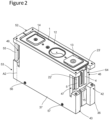
- the first electrode assembly 2 is inserted into the first supporting tool 36 and the second electrode assembly 3 is inserted into the second supporting tool 37 as illustrated in figure 2 .
- Each first side end 42, 43 comprises a first opening 46, 47 intended to be positioned opposite a first connection element 4, 5 of one of the electrode assemblies 2, 3.
- the first openings 46, 47 have a rectangular shape.
- first side ends 42, 43 and second side ends 52, 53 of the respective supporting tools 36, 37 are in contact at the bottom part 58 of the supporting tools 36, 37 and the assembly tool is formed, as shown in figure 2 .
- Each first side end 42, 43 of the supporting tools 36, 37 comprises a first pivoting flap 54', 55' mounted rotatably relative to the supporting tool 36, 37 about a first rotation axis A1 passing through one of the first openings 46, 47.
- the first pivoting flaps 54', 55' are positioned in the first openings 46, 47 of the supporting tool 36, 37.
- the pivoting flaps 54, 55, 54', 55' have a rectangular shape with a curved shape.
- the manufacturing process then comprises a step of pivoting the two first pivoting flaps 54', 55' so that they are in abutment against the respective first tabs 30, 31 of the first connection element 4, 5 and a step of pivoting the two second pivoting flaps 54, 55 so that they are in abutment against the respective second tabs 32, 33 of the second connection element 6, 7.
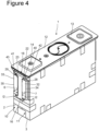
- the second collector 16 comprises two second lateral areas 40, 41 which are each positioned between one of the second end portions 22, 23 of the second tabs 32, 33 and a second inner part 42, 43 of the second foot terminal 28, 29 as shown in figure 4 .
- the first collector 15 and the first tabs 30, 31 are arranged in the same manner.
- the second tabs 32, 33 and the second collector 16 have a rectangular shape.
- Each first pivoting flap 54', 55' comprises a first end 50' having a first oblong hole 51', 52', for instance, aligned parallel to the first rotation axis A1.
- the first oblong holes 51', 52' extend along quite the whole first pivoting flap 54', 55' heigh.
- each first pivoting flap 54', 55' can comprise holes with a different shape, as circular shape, for instance.
- laser welding is performed through the first pivoting flaps 54', 55' and preferably through oblong holes 51', 52' formed in the first pivoting flaps 54', 55'.
- the first end portions 22', 23' are welded to the first collectors 15 over a width of at least 3 mm and preferably at least 6 mm.
- This proportion ensures a strong weld and enables the second tab to be bent correctly.
- Each second pivoting flap 54, 55 comprises a second end 50 having a second oblong hole 51 aligned parallel to the second rotation axis A2.
- the oblong holes 51 extend along quite the whole second pivoting flap 54, 55 heigh.
- each second pivoting flap 54, 55 can comprise holes with a different shape, as circular shape, for instance.
- laser welding is performed through the second pivoting flaps 54, 55 and preferably through the second oblong holes 51 formed in the second pivoting flaps 54, 55.
- the second end portions 22, 23 are welded to the respective second collectors 16 over a second width l 2 of at least 3 mm and preferably at least 6 mm, as illustrated in figure 4 .
- This proportion ensures a strong weld and enables the second tab to be bent correctly.
- the second width l 2 is greater than or equal to a quarter of the width L 2 of the second tab 32, 33 and less than or equal to half the width L 2 of the second tab 32, 33.
Landscapes
- Chemical & Material Sciences (AREA)
- Chemical Kinetics & Catalysis (AREA)
- Electrochemistry (AREA)
- General Chemical & Material Sciences (AREA)
- Engineering & Computer Science (AREA)
- Manufacturing & Machinery (AREA)
- Physics & Mathematics (AREA)
- Optics & Photonics (AREA)
- Mechanical Engineering (AREA)
- Connection Of Batteries Or Terminals (AREA)
Priority Applications (1)
| Application Number | Priority Date | Filing Date | Title |
|---|---|---|---|
| EP23307239.6A EP4576291A1 (de) | 2023-12-18 | 2023-12-18 | Verfahren zur herstellung einer elektrochemischen zelle mit gleitwerkzeugen |
Applications Claiming Priority (1)
| Application Number | Priority Date | Filing Date | Title |
|---|---|---|---|
| EP23307239.6A EP4576291A1 (de) | 2023-12-18 | 2023-12-18 | Verfahren zur herstellung einer elektrochemischen zelle mit gleitwerkzeugen |
Publications (1)
| Publication Number | Publication Date |
|---|---|
| EP4576291A1 true EP4576291A1 (de) | 2025-06-25 |
Family
ID=89541957
Family Applications (1)
| Application Number | Title | Priority Date | Filing Date |
|---|---|---|---|
| EP23307239.6A Pending EP4576291A1 (de) | 2023-12-18 | 2023-12-18 | Verfahren zur herstellung einer elektrochemischen zelle mit gleitwerkzeugen |
Country Status (1)
| Country | Link |
|---|---|
| EP (1) | EP4576291A1 (de) |
Citations (6)
| Publication number | Priority date | Publication date | Assignee | Title |
|---|---|---|---|---|
| KR101486232B1 (ko) * | 2013-05-10 | 2015-01-26 | 주식회사 엘지화학 | 전지셀 이송 장치 |
| KR20160104931A (ko) * | 2015-02-27 | 2016-09-06 | 주식회사 엘지화학 | 전지팩용 레이저 용접 지그 |
| KR102037209B1 (ko) * | 2012-12-31 | 2019-11-26 | 에스케이이노베이션 주식회사 | 이차 전지용 배터리 팩 조립 지그 및 이를 이용한 배터리 팩 조립 방법 |
| US20210384513A1 (en) | 2018-10-05 | 2021-12-09 | Gs Yuasa International Ltd. | Energy storage device and method for manufacturing the same |
| US20220013804A1 (en) * | 2018-12-13 | 2022-01-13 | Bayerische Motoren Werke Aktiengesellschaft | Energy Storage Cell, Production Method and Apparatus for Carrying Out Such a Method |
| EP4024582A1 (de) * | 2020-03-26 | 2022-07-06 | Lg Energy Solution, Ltd. | Batteriepack-ladevorrichtung und batteriepack-ladeverfahren damit |
-
2023
- 2023-12-18 EP EP23307239.6A patent/EP4576291A1/de active Pending
Patent Citations (6)
| Publication number | Priority date | Publication date | Assignee | Title |
|---|---|---|---|---|
| KR102037209B1 (ko) * | 2012-12-31 | 2019-11-26 | 에스케이이노베이션 주식회사 | 이차 전지용 배터리 팩 조립 지그 및 이를 이용한 배터리 팩 조립 방법 |
| KR101486232B1 (ko) * | 2013-05-10 | 2015-01-26 | 주식회사 엘지화학 | 전지셀 이송 장치 |
| KR20160104931A (ko) * | 2015-02-27 | 2016-09-06 | 주식회사 엘지화학 | 전지팩용 레이저 용접 지그 |
| US20210384513A1 (en) | 2018-10-05 | 2021-12-09 | Gs Yuasa International Ltd. | Energy storage device and method for manufacturing the same |
| US20220013804A1 (en) * | 2018-12-13 | 2022-01-13 | Bayerische Motoren Werke Aktiengesellschaft | Energy Storage Cell, Production Method and Apparatus for Carrying Out Such a Method |
| EP4024582A1 (de) * | 2020-03-26 | 2022-07-06 | Lg Energy Solution, Ltd. | Batteriepack-ladevorrichtung und batteriepack-ladeverfahren damit |
Similar Documents
| Publication | Publication Date | Title |
|---|---|---|
| CN111048728B (zh) | 二次电池、电池模块以及使用二次电池作为电源的装置 | |
| EP3305460B1 (de) | Batteriemodul, verfahren zum schweissen von elektrodenleitungen von batteriezellen in einem batteriemodul und batteriepack mit dem batteriemodul | |
| EP3561902B1 (de) | Batteriemodul, batteriepack mit dem batteriemodul und fahrzeug mit dem batteriepack | |
| EP4395050A1 (de) | Batteriezelle, batterie und elektrische vorrichtung | |
| EP4266475A2 (de) | Batterie, batterieanordnungsverfahren und batteriepack | |
| US12138716B2 (en) | Jig for tack welding of battery cell electrode lead | |
| EP3731302B1 (de) | Batteriemodul, batteriepack mit solch einem batteriemodul und fahrzeug mit solch einem batteriepack | |
| US20240372131A1 (en) | Guide and flattening mechanism, and guide and flattening device | |
| JP2021120961A (ja) | 角形二次電池及びそれを用いた組電池 | |
| KR20060022358A (ko) | 이차 전지와 이에 사용되는 전극 조립체 | |
| US20140023913A1 (en) | Prismatic secondary battery | |
| EP4576291A1 (de) | Verfahren zur herstellung einer elektrochemischen zelle mit gleitwerkzeugen | |
| JP2023089231A (ja) | 電極端子およびその利用 | |
| US20240363954A1 (en) | Battery and Electric Device | |
| EP4574331A1 (de) | Verfahren zur herstellung einer elektrochemischen zelle mit schwenkbaren werkzeugen | |
| CN119833858B (zh) | 电池单体、电池单体的制备方法、电池及其用电装置 | |
| EP4576290A1 (de) | Verfahren zur herstellung einer elektrochemischen zelle | |
| EP4683095A1 (de) | Adapterfolie, sekundärbatterie, batterieanordnung und elektronische vorrichtung | |
| CN223638560U (zh) | 电池单体、电池装置和用电装置 | |
| CN221994665U (zh) | 电池单体、电池装置、用电装置及储能装置 | |
| CN119833768B (zh) | 支撑装置、焊接设备、电池单体、电池装置和用电装置 | |
| US20240079740A1 (en) | Method of assembling traction battery pack and traction battery pack assembly | |
| CN118249049B (zh) | 电池单体、电池、用电设备及电池单体的制造方法 | |
| US20250372822A1 (en) | Configurations for optimizing battery cell-to-busbar electrical connections | |
| EP4664662A1 (de) | Sekundärbatterie und verfahren zur herstellung einer sekundärbatterie |
Legal Events
| Date | Code | Title | Description |
|---|---|---|---|
| PUAI | Public reference made under article 153(3) epc to a published international application that has entered the european phase |
Free format text: ORIGINAL CODE: 0009012 |
|
| STAA | Information on the status of an ep patent application or granted ep patent |
Free format text: STATUS: THE APPLICATION HAS BEEN PUBLISHED |
|
| AK | Designated contracting states |
Kind code of ref document: A1 Designated state(s): AL AT BE BG CH CY CZ DE DK EE ES FI FR GB GR HR HU IE IS IT LI LT LU LV MC ME MK MT NL NO PL PT RO RS SE SI SK SM TR |
|
| STAA | Information on the status of an ep patent application or granted ep patent |
Free format text: STATUS: REQUEST FOR EXAMINATION WAS MADE |
|
| 17P | Request for examination filed |
Effective date: 20251224 |