EP4576291A1 - Process for manufacturing an electrochemical cell with slided tools - Google Patents
Process for manufacturing an electrochemical cell with slided tools Download PDFInfo
- Publication number
- EP4576291A1 EP4576291A1 EP23307239.6A EP23307239A EP4576291A1 EP 4576291 A1 EP4576291 A1 EP 4576291A1 EP 23307239 A EP23307239 A EP 23307239A EP 4576291 A1 EP4576291 A1 EP 4576291A1
- Authority
- EP
- European Patent Office
- Prior art keywords
- electrode
- supporting
- pivoting
- assembly
- tool
- Prior art date
- Legal status (The legal status is an assumption and is not a legal conclusion. Google has not performed a legal analysis and makes no representation as to the accuracy of the status listed.)
- Pending
Links
Images


Classifications
-
- B—PERFORMING OPERATIONS; TRANSPORTING
- B23—MACHINE TOOLS; METAL-WORKING NOT OTHERWISE PROVIDED FOR
- B23K—SOLDERING OR UNSOLDERING; WELDING; CLADDING OR PLATING BY SOLDERING OR WELDING; CUTTING BY APPLYING HEAT LOCALLY, e.g. FLAME CUTTING; WORKING BY LASER BEAM
- B23K37/00—Auxiliary devices or processes, not specially adapted for a procedure covered by only one of the other main groups of this subclass
- B23K37/04—Auxiliary devices or processes, not specially adapted for a procedure covered by only one of the other main groups of this subclass for holding or positioning work
- B23K37/0426—Fixtures for other work
- B23K37/0435—Clamps
- B23K37/0443—Jigs
-
- H—ELECTRICITY
- H01—ELECTRIC ELEMENTS
- H01M—PROCESSES OR MEANS, e.g. BATTERIES, FOR THE DIRECT CONVERSION OF CHEMICAL ENERGY INTO ELECTRICAL ENERGY
- H01M10/00—Secondary cells; Manufacture thereof
- H01M10/04—Construction or manufacture in general
- H01M10/0404—Machines for assembling batteries
-
- H—ELECTRICITY
- H01—ELECTRIC ELEMENTS
- H01M—PROCESSES OR MEANS, e.g. BATTERIES, FOR THE DIRECT CONVERSION OF CHEMICAL ENERGY INTO ELECTRICAL ENERGY
- H01M50/00—Constructional details or processes of manufacture of the non-active parts of electrochemical cells other than fuel cells, e.g. hybrid cells
- H01M50/10—Primary casings; Jackets or wrappings
- H01M50/102—Primary casings; Jackets or wrappings characterised by their shape or physical structure
- H01M50/103—Primary casings; Jackets or wrappings characterised by their shape or physical structure prismatic or rectangular
-
- H—ELECTRICITY
- H01—ELECTRIC ELEMENTS
- H01M—PROCESSES OR MEANS, e.g. BATTERIES, FOR THE DIRECT CONVERSION OF CHEMICAL ENERGY INTO ELECTRICAL ENERGY
- H01M50/00—Constructional details or processes of manufacture of the non-active parts of electrochemical cells other than fuel cells, e.g. hybrid cells
- H01M50/10—Primary casings; Jackets or wrappings
- H01M50/147—Lids or covers
- H01M50/148—Lids or covers characterised by their shape
- H01M50/15—Lids or covers characterised by their shape for prismatic or rectangular cells
-
- H—ELECTRICITY
- H01—ELECTRIC ELEMENTS
- H01M—PROCESSES OR MEANS, e.g. BATTERIES, FOR THE DIRECT CONVERSION OF CHEMICAL ENERGY INTO ELECTRICAL ENERGY
- H01M50/00—Constructional details or processes of manufacture of the non-active parts of electrochemical cells other than fuel cells, e.g. hybrid cells
- H01M50/50—Current conducting connections for cells or batteries
- H01M50/531—Electrode connections inside a battery casing
- H01M50/533—Electrode connections inside a battery casing characterised by the shape of the leads or tabs
-
- H—ELECTRICITY
- H01—ELECTRIC ELEMENTS
- H01M—PROCESSES OR MEANS, e.g. BATTERIES, FOR THE DIRECT CONVERSION OF CHEMICAL ENERGY INTO ELECTRICAL ENERGY
- H01M50/00—Constructional details or processes of manufacture of the non-active parts of electrochemical cells other than fuel cells, e.g. hybrid cells
- H01M50/50—Current conducting connections for cells or batteries
- H01M50/531—Electrode connections inside a battery casing
- H01M50/536—Electrode connections inside a battery casing characterised by the method of fixing the leads to the electrodes, e.g. by welding
-
- H—ELECTRICITY
- H01—ELECTRIC ELEMENTS
- H01M—PROCESSES OR MEANS, e.g. BATTERIES, FOR THE DIRECT CONVERSION OF CHEMICAL ENERGY INTO ELECTRICAL ENERGY
- H01M50/00—Constructional details or processes of manufacture of the non-active parts of electrochemical cells other than fuel cells, e.g. hybrid cells
- H01M50/50—Current conducting connections for cells or batteries
- H01M50/531—Electrode connections inside a battery casing
- H01M50/54—Connection of several leads or tabs of plate-like electrode stacks, e.g. electrode pole straps or bridges
-
- H—ELECTRICITY
- H01—ELECTRIC ELEMENTS
- H01M—PROCESSES OR MEANS, e.g. BATTERIES, FOR THE DIRECT CONVERSION OF CHEMICAL ENERGY INTO ELECTRICAL ENERGY
- H01M50/00—Constructional details or processes of manufacture of the non-active parts of electrochemical cells other than fuel cells, e.g. hybrid cells
- H01M50/50—Current conducting connections for cells or batteries
- H01M50/543—Terminals
- H01M50/552—Terminals characterised by their shape
- H01M50/553—Terminals adapted for prismatic, pouch or rectangular cells
-
- Y—GENERAL TAGGING OF NEW TECHNOLOGICAL DEVELOPMENTS; GENERAL TAGGING OF CROSS-SECTIONAL TECHNOLOGIES SPANNING OVER SEVERAL SECTIONS OF THE IPC; TECHNICAL SUBJECTS COVERED BY FORMER USPC CROSS-REFERENCE ART COLLECTIONS [XRACs] AND DIGESTS
- Y02—TECHNOLOGIES OR APPLICATIONS FOR MITIGATION OR ADAPTATION AGAINST CLIMATE CHANGE
- Y02E—REDUCTION OF GREENHOUSE GAS [GHG] EMISSIONS, RELATED TO ENERGY GENERATION, TRANSMISSION OR DISTRIBUTION
- Y02E60/00—Enabling technologies; Technologies with a potential or indirect contribution to GHG emissions mitigation
- Y02E60/10—Energy storage using batteries
-
- Y—GENERAL TAGGING OF NEW TECHNOLOGICAL DEVELOPMENTS; GENERAL TAGGING OF CROSS-SECTIONAL TECHNOLOGIES SPANNING OVER SEVERAL SECTIONS OF THE IPC; TECHNICAL SUBJECTS COVERED BY FORMER USPC CROSS-REFERENCE ART COLLECTIONS [XRACs] AND DIGESTS
- Y02—TECHNOLOGIES OR APPLICATIONS FOR MITIGATION OR ADAPTATION AGAINST CLIMATE CHANGE
- Y02P—CLIMATE CHANGE MITIGATION TECHNOLOGIES IN THE PRODUCTION OR PROCESSING OF GOODS
- Y02P70/00—Climate change mitigation technologies in the production process for final industrial or consumer products
- Y02P70/50—Manufacturing or production processes characterised by the final manufactured product
Definitions
- Electrochemical cells are used in electric or hybrid vehicles, i.e. powered at least partly by electrical energy, for example.
- Motor vehicles with electric or hybrid traction or propulsion comprise one or more battery modules connected to a power network to supply an electric motor (traction or propulsion).
- Each battery module comprises at least one electrochemical cell generating current by chemical reaction, for example of the lithium-ion (or Li-ion), Ni-Mh, Ni-Cd or lead type.
- the two positive electrode tabs are welded to a positive current collector by ultrasonic welding.
- the two negative electrode tabs are ultrasonically welded to a negative current collector.
- the two electrode assemblies are thus joined by the two collectors.
- Each current collector is in the form of an L-shaped piece of sheet metal comprising a first wing for welding the current collector to the electrode tab by ultrasonic welding and a second wing for welding the current collector to a foot terminal by laser welding. A fold is made to connect the first wing to the second wing.
- the current electrochemical cell manufacturing process for electrochemical cells comprising tabs on the top then comprises a preliminary ultrasonic welding step to weld the tabs of a positive electrode stack made of aluminum to each other and make a bundled positive tab, and a main ultrasonic welding step to weld the bundled tab to the positive current collector made of aluminum.
- a laser beam welding is a potential replacement of the main ultrasonic welding.
- the same steps are applied on the negative terminal side made of copper.
- the laser beam welding is also a potential replacement of the main ultrasonic welding.
- electrochemical cells comprise two electrode assemblies with connecting elements positioned on their side faces.
- the manufacturing process is simplified and faster by using a single welding technic. An ultrasonic welding on the first connection elements is no more needed.
- first connection elements and the first collector are made of copper, the second connection elements and the second collector being made of aluminum.
- the invention also relates to a tool for assembling two electrode assemblies of an electrochemical cell comprising two electrode assemblies each comprising stacks of positive electrodes connected to each other and stacks of negative electrodes connected to each other.
- Each electrode assembly comprises a first connection element at a first side face of the electrode assembly and is electrically connected to the negative electrode stacks and a second connection element at a second side face of the electrode assembly and being electrically connected to the positive electrode stacks.
- the assembly tool comprises two supporting tools comprising each a housing configured to receive one of the electrode assemblies, each supporting tool being configured to translate toward the two electrode assemblies.
- each supporting tool comprises two holes at a bottom part of the supporting tool intended to receive two respective rods supported by a basement, the supporting tools being able to slide along the rods relative to the basement.
- each first side end of the supporting tools comprises a first opening intended to be positioned opposite a first connection element of one of the electrode assemblies.
- each first side end of the supporting tools comprises a first pivoting flap mounted rotatably relative to the supporting tool about a first rotation axis passing through one of the first openings, the first pivoting flaps being positioned in the first openings of the supporting tool.
- each supporting tools comprises a second lateral end having a second opening intended to be positioned opposite the second connection element of one of the electrode assemblies.
- each second side end of the supporting tool comprises a second pivoting flap mounted rotatably relative to the supporting tool about a second rotation axis passing through each second opening, the second pivoting flaps being positioned in the respective second openings of the supporting tool.
- each pivoting flap comprises an oblong hole aligned parallel to the second rotation axis.
- the invention relates to an electrochemical cell comprising two electrode assemblies 2, 3, as illustrated in figure 1 .
- Each electrode assembly 2, 3 comprises stacks of negative electrodes connected to each other by a first connecting element 4, 5 made of copper and stacks of positive electrodes connected to each other by a second connecting element 6, 7 made of aluminium.
- the electrochemical cell can be used, for example, in an electric or hybrid vehicle, i.e. powered at least partially by electrical energy.
- the electrode stacks are separated by a separator and are known as a "stack".
- the interconnected positive electrodes are connected to a positive terminal, and the interconnected negative electrodes are connected to a negative terminal.
- the positive and negative electrodes are housed in a hollow metal casing, generally made of aluminum. Once the electrode assembly has been integrated into the housing, an upper wall, in the form of a plate forming a cover 12, is welded to the housing by laser, for example, to provide the structural connection and sealing of the electrochemical cell.
- the housing has a parallelepiped shape with a rectangular cross-section and comprises two opposing longitudinal walls and two opposing transverse walls perpendicular to the longitudinal walls.
- a positive terminal 14 and a negative terminal 13 are arranged on the cover 12.
- the invention relates to a process for manufacturing an electrochemical cell comprising a step of providing two electrode assemblies 2, 3 including a first electrode assembly 2 and a second electrode assembly 3.
- Each electrode assembly 2, 3 comprises stacks of positive electrodes connected to each other, and stacks of negative electrodes connected to each other.
- each electrode assembly 2, 3 comprises a first connection element 4, 5 at a first side face 8, 9 of the electrode assembly 2, 3.
- Each first connection element 4, 5 is an extension of a part of the negative electrodes located inside the negative electrode stacks of the electrode assemblies 2, 3. The parts of the negative electrodes are welded together to form the first connection element 4, 5.
- Each first connection element 4, 5 comprises a first foot terminal 26, 27 extending from the first side face 8, 9 of the electrode assemblies 2, 3. Each first foot terminal 26, 27 is formed by an extension of the negative electrodes located inside the negative electrode stacks of the electrode assemblies 2, 3. Each first connection element 4, 5 comprises also a first tab 30, 31 extending from the first foot terminal 26, 27 and a first bending section 24, 25 located between the foot terminal 26, 27 and the first tab 30, 31.
- each first tab 30, 31 projects from the first foot terminal 26, 27, perpendicular to the first side face 8, 9 of the electrode assembly 2, 3 (not shown).
- Each electrode assembly 2, 3 also comprises a second connecting element 6, 7 located at a second side face 10, 11 of the electrode assembly 2, 3.
- Each second connection element 2, 3 is an extension of a part of the positive electrodes located inside the positive electrode stacks of the electrode assemblies 2, 3. The parts of the positive electrodes are welded together to form the second connection element 2, 3.
- Each second connecting element 6, 7 comprises a second foot terminal 28, 29 extending from a second side face 10, 11 of the electrode assembly 2, 3.
- Each second foot terminal 28, 29 is formed by an extension of the negative electrodes located inside the negative electrode stacks of the electrode assemblies 2, 3.
- Each second connecting element 6, 7 also comprises a second tab 32, 33 extending from the second foot terminal 28, 29 and a second bending section 34, 35 located between the second foot terminal 28, 29 and the second tab 32, 33.
- each second tab 32, 33 projects from the second foot terminal 28, 29 and perpendicularly from the second side face 10, 11 of the electrode assembly 2, 3.
- the two electrode assemblies 2, 3 are joined together to form an electrochemical cell assembly 1 comprising a cover 12 having a negative terminal 13 electrically connected to a first collector 15 and a positive terminal 14 electrically connected to a second collector 16.
- the two electrode assemblies 2, 3 are aligned parallel and positioned perpendicular to the cover 12.
- the first connection elements 4, 5 and the first collector 15 are made of copper.
- the second connecting elements 6, 7 and the second collector 16 are made of aluminum.
- Each supporting tool 36, 37 comprises two holes 56, 57 at a bottom part 58, 59 of the supporting tool 36, 37 intended to receive two respective rods supported by a basement.
- the supporting tools 36, 37 can slide along the rods relative to the basement.
- the rods are guiding means enabling the supporting tools 36, 37 to translate according to the directions X1 and X2.
- the holes 56, 57 extend across the supporting tool 36, 37 perpendicularly to a main wall 62, 63 of the supporting tool 36, 37.
- Each supporting tool 36, 37 has a U-shaped section.
- First side ends 42, 43 and second side ends 52, 53 extend perpendicularly from the main wall 62, 63.
- the rods are parallel to each other and extends below the two electrode assemblies 2, 3.
- a first supporting tool 36 translates toward a first electrode assembly 2 according to a first direction X1 and a second supporting tool 37 translates toward a second electrode assembly 3 according to a second direction X2, parallel and opposite to the first direction X1.
- the two supporting tools 36, 37 form an assembly tool embedding the electrode assemblies 2, 3.
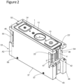
- the first electrode assembly 2 is inserted into the first supporting tool 36 and the second electrode assembly 3 is inserted into the second supporting tool 37 as illustrated in figure 2 .
- Each first side end 42, 43 comprises a first opening 46, 47 intended to be positioned opposite a first connection element 4, 5 of one of the electrode assemblies 2, 3.
- the first openings 46, 47 have a rectangular shape.
- first side ends 42, 43 and second side ends 52, 53 of the respective supporting tools 36, 37 are in contact at the bottom part 58 of the supporting tools 36, 37 and the assembly tool is formed, as shown in figure 2 .
- Each first side end 42, 43 of the supporting tools 36, 37 comprises a first pivoting flap 54', 55' mounted rotatably relative to the supporting tool 36, 37 about a first rotation axis A1 passing through one of the first openings 46, 47.
- the first pivoting flaps 54', 55' are positioned in the first openings 46, 47 of the supporting tool 36, 37.
- the pivoting flaps 54, 55, 54', 55' have a rectangular shape with a curved shape.
- the manufacturing process then comprises a step of pivoting the two first pivoting flaps 54', 55' so that they are in abutment against the respective first tabs 30, 31 of the first connection element 4, 5 and a step of pivoting the two second pivoting flaps 54, 55 so that they are in abutment against the respective second tabs 32, 33 of the second connection element 6, 7.
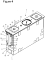
- the second collector 16 comprises two second lateral areas 40, 41 which are each positioned between one of the second end portions 22, 23 of the second tabs 32, 33 and a second inner part 42, 43 of the second foot terminal 28, 29 as shown in figure 4 .
- the first collector 15 and the first tabs 30, 31 are arranged in the same manner.
- the second tabs 32, 33 and the second collector 16 have a rectangular shape.
- Each first pivoting flap 54', 55' comprises a first end 50' having a first oblong hole 51', 52', for instance, aligned parallel to the first rotation axis A1.
- the first oblong holes 51', 52' extend along quite the whole first pivoting flap 54', 55' heigh.
- each first pivoting flap 54', 55' can comprise holes with a different shape, as circular shape, for instance.
- laser welding is performed through the first pivoting flaps 54', 55' and preferably through oblong holes 51', 52' formed in the first pivoting flaps 54', 55'.
- the first end portions 22', 23' are welded to the first collectors 15 over a width of at least 3 mm and preferably at least 6 mm.
- This proportion ensures a strong weld and enables the second tab to be bent correctly.
- Each second pivoting flap 54, 55 comprises a second end 50 having a second oblong hole 51 aligned parallel to the second rotation axis A2.
- the oblong holes 51 extend along quite the whole second pivoting flap 54, 55 heigh.
- each second pivoting flap 54, 55 can comprise holes with a different shape, as circular shape, for instance.
- laser welding is performed through the second pivoting flaps 54, 55 and preferably through the second oblong holes 51 formed in the second pivoting flaps 54, 55.
- the second end portions 22, 23 are welded to the respective second collectors 16 over a second width l 2 of at least 3 mm and preferably at least 6 mm, as illustrated in figure 4 .
- This proportion ensures a strong weld and enables the second tab to be bent correctly.
- the second width l 2 is greater than or equal to a quarter of the width L 2 of the second tab 32, 33 and less than or equal to half the width L 2 of the second tab 32, 33.
Landscapes
- Chemical & Material Sciences (AREA)
- Chemical Kinetics & Catalysis (AREA)
- Electrochemistry (AREA)
- General Chemical & Material Sciences (AREA)
- Engineering & Computer Science (AREA)
- Manufacturing & Machinery (AREA)
- Physics & Mathematics (AREA)
- Optics & Photonics (AREA)
- Mechanical Engineering (AREA)
- Connection Of Batteries Or Terminals (AREA)
Abstract
The invention relates to a process for manufacturing an electrochemical cell comprising in particular:- a step for providing two electrode assemblies (2, 3),- a step of translating two supporting tools (36, 37) toward the electrode assemblies to insert each electrode assembly into one of the supporting tools,- a step of pivoting two first pivoting flaps (54', 55') of the supporting tools, up to abutment against first tabs (30, 31),- a step of pivoting two second pivoting flaps (54, 55) of the supporting tools, up to abutment against second tabs (32, 33),- a first step of welding the first connection elements (4, 5) to the first collector,- a second step of welding the second connection elements to the second collector.
Description
- The invention relates to the technical field of energy storage devices, and in particular to a process for manufacturing an electrochemical cell.
- Electrochemical cells are used in electric or hybrid vehicles, i.e. powered at least partly by electrical energy, for example.
- Motor vehicles with electric or hybrid traction or propulsion comprise one or more battery modules connected to a power network to supply an electric motor (traction or propulsion).
- The battery modules are grouped together in a housing to form a battery pack, which generally contains a mounting interface and connection terminals.
- Each battery module comprises at least one electrochemical cell generating current by chemical reaction, for example of the lithium-ion (or Li-ion), Ni-Mh, Ni-Cd or lead type.
- The electrochemical cell comprises two electrode assemblies, each comprising stacks of positive electrodes connected to each other by a positive electrode tab generally made of aluminum, and stacks of negative electrodes connected to each other by a negative electrode tab generally made of copper.
- The two positive electrode tabs are welded to a positive current collector by ultrasonic welding. The two negative electrode tabs are ultrasonically welded to a negative current collector. The two electrode assemblies are thus joined by the two collectors.
- Document
US2021384513A1 describes an example of two current collectors, each associated with a terminal (positive or negative) and positioned on a top part of the electrode assemblies, between the electrode assemblies and a cover comprising the positive and negative terminals. - Each current collector is in the form of an L-shaped piece of sheet metal comprising a first wing for welding the current collector to the electrode tab by ultrasonic welding and a second wing for welding the current collector to a foot terminal by laser welding. A fold is made to connect the first wing to the second wing.
- Each foot terminal is connected to one of the positive or negative terminals provided on the cover that closes a metal housing in which the two electrode assemblies are housed.
- The current electrochemical cell manufacturing process for electrochemical cells comprising tabs on the top then comprises a preliminary ultrasonic welding step to weld the tabs of a positive electrode stack made of aluminum to each other and make a bundled positive tab, and a main ultrasonic welding step to weld the bundled tab to the positive current collector made of aluminum. However, the use of a laser beam welding is a potential replacement of the main ultrasonic welding.
- The same steps are applied on the negative terminal side made of copper. However, the laser beam welding is also a potential replacement of the main ultrasonic welding.
- Further, some electrochemical cells comprise two electrode assemblies with connecting elements positioned on their side faces.
- However, it is difficult to apply a laser beam welding to the negative electrode bundled tab to the negative current collector, which are both made of copper, and does not working well with currently prevailing laser beam welding technology due to its high reflectivity. Just as it is equally difficult to apply an ultrasonic welding for the positive electrode bundled tab to the positive current collector, which are made of aluminum, and it does not have enough hardness for good ultrasonic welding.
- These two different welding methods are, however, essential, but they are carried out in several stages, which lengthens the process time and at the risks of poor welding quality. The process is also complex to implement.
- The invention aims to solve some or all of the disadvantages of the prior art, in particular by proposing a faster process for manufacturing an electrochemical cell.
- To this end, according to a first aspect of the invention, a process for manufacturing an electrochemical cell is proposed, comprising:
- a step of providing an electrochemical cell assembly comprising two electrode assemblies each comprising stacks of positive electrodes connected to each other and stacks of negative electrodes connected to each other, each electrode assembly comprising a first connection element at a first side face of the electrode assembly and being electrically connected to the negative electrode stacks, and a second connection element at a second side face of the electrode assembly and being electrically connected to the positive electrode stacks, the first connection element having a first tab in abutment against a first collector connected to a negative terminal of a cover, the second connection element having second tabs in abutment against a second collector connected to a positive terminal of the cover,
- a step of translating two supporting tools toward the electrode assemblies to insert each electrode assembly into one of the respective supporting tools, the two supporting tools forming an assembly tool embedding the electrode assemblies,
- a step of pivoting two first pivoting flaps, each rotatably mounted on a first side end of one of the supporting tools, up to abutment against the respective first tabs,
- a step of pivoting two second pivoting flaps, each rotatably mounted on a second side end of one of the supporting tools, up to abutment against the respective second tabs,
- a first step of welding the first connection elements to the first collector,
- a second step of welding the second connection elements to the second collector, and
- a step of translating the two supporting tools in a direction opposite to the electrode assemblies to remove each electrode assembly from the respective supporting tools.
- The invention thus provides a faster and simpler method for manufacturing an electrochemical cell due to a single step of laser welding for the both sides.
- The use of two electrode assemblies with connecting elements positioned on their side faces simplifies the manufacturing process and reduces the time of the process.
- Alternatively, the first and second welding steps are performed by laser welding.
- The manufacturing process is simplified and faster by using a single welding technic. An ultrasonic welding on the first connection elements is no more needed.
- Alternatively, the first connection elements and the first collector are made of copper, the second connection elements and the second collector being made of aluminum.
- Alternatively, the first and second steps of welding are performed through the first and second pivoting flaps and preferably through oblong holes formed in the pivoting flaps.
- This enables to weld quicky the second connecting elements to the second collector.
- The invention also relates to a tool for assembling two electrode assemblies of an electrochemical cell comprising two electrode assemblies each comprising stacks of positive electrodes connected to each other and stacks of negative electrodes connected to each other. Each electrode assembly comprises a first connection element at a first side face of the electrode assembly and is electrically connected to the negative electrode stacks and a second connection element at a second side face of the electrode assembly and being electrically connected to the positive electrode stacks. The assembly tool comprises two supporting tools comprising each a housing configured to receive one of the electrode assemblies, each supporting tool being configured to translate toward the two electrode assemblies.
- This provides a faster and simpler method for manufacturing an electrochemical cell having connection elements at both side faces of the electrochemical cell.
- Alternatively, each supporting tool comprises two holes at a bottom part of the supporting tool intended to receive two respective rods supported by a basement, the supporting tools being able to slide along the rods relative to the basement.
- This provides a simpler solution for moving the supporting tools.
- Alternatively, each first side end of the supporting tools comprises a first opening intended to be positioned opposite a first connection element of one of the electrode assemblies.
- Alternatively, each first side end of the supporting tools comprises a first pivoting flap mounted rotatably relative to the supporting tool about a first rotation axis passing through one of the first openings, the first pivoting flaps being positioned in the first openings of the supporting tool.
- Alternatively, each supporting tools comprises a second lateral end having a second opening intended to be positioned opposite the second connection element of one of the electrode assemblies.
- Alternatively, each second side end of the supporting tool comprises a second pivoting flap mounted rotatably relative to the supporting tool about a second rotation axis passing through each second opening, the second pivoting flaps being positioned in the respective second openings of the supporting tool.
- Alternatively, each pivoting flap comprises an oblong hole aligned parallel to the second rotation axis.
- This enables to weld quicky and in a simple manner the first and second connecting elements to the first and second collectors.
- Further features and advantages of the invention will become apparent from the following description, with reference to the appended figures, which illustrate:
- -
figure 1 : a schematic view of two electrode assemblies of an electrochemical cell during a step of sliding two supporting tools toward two electrode assemblies; - -
figure 2 : a schematic view of each electrode assembly inserted into a respective supporting tool; - -
figure 3 : a schematic view of two pivoting flaps after a step of pivoting the pivoting flaps to bend the second connection elements; - -
figure 4 : a schematic view of the two second connection elements after a step of welding the second connection elements to a second collector. - For greater clarity, identical or similar elements are marked by identical reference signs throughout the figures.
- The invention relates to an electrochemical cell comprising two
electrode assemblies figure 1 . - Each
electrode assembly element element - The electrochemical cell can be used, for example, in an electric or hybrid vehicle, i.e. powered at least partially by electrical energy.
- The electrode stacks are separated by a separator and are known as a "stack". The interconnected positive electrodes are connected to a positive terminal, and the interconnected negative electrodes are connected to a negative terminal.
- It is known to assemble, in series and/or in parallel, a plurality of electrochemical cells to create battery modules.
- Several modules are grouped together in a housing to form a battery pack, which generally contains a mounting interface and connection terminals.
- The positive and negative electrodes are housed in a hollow metal casing, generally made of aluminum. Once the electrode assembly has been integrated into the housing, an upper wall, in the form of a plate forming a
cover 12, is welded to the housing by laser, for example, to provide the structural connection and sealing of the electrochemical cell. - The housing has a parallelepiped shape with a rectangular cross-section and comprises two opposing longitudinal walls and two opposing transverse walls perpendicular to the longitudinal walls. A
positive terminal 14 and anegative terminal 13 are arranged on thecover 12. - The invention relates to a process for manufacturing an electrochemical cell comprising a step of providing two
electrode assemblies first electrode assembly 2 and asecond electrode assembly 3. Eachelectrode assembly - As illustrated in
figure 1 , eachelectrode assembly first connection element first side face electrode assembly first connection element electrode assemblies first connection element - Each
first connection element first foot terminal first side face electrode assemblies first foot terminal electrode assemblies first connection element first tab first foot terminal first bending section foot terminal first tab - Before the manufacturing process starts, each
first tab first foot terminal first side face electrode assembly 2, 3 (not shown). - Each
electrode assembly element second side face electrode assembly second connection element electrode assemblies second connection element - Each second connecting
element second foot terminal second side face electrode assembly second foot terminal electrode assemblies element second tab second foot terminal second bending section second foot terminal second tab - Before the manufacturing process starts, each
second tab second foot terminal second side face electrode assembly - The two
electrode assemblies electrochemical cell assembly 1 comprising acover 12 having anegative terminal 13 electrically connected to afirst collector 15 and apositive terminal 14 electrically connected to asecond collector 16. The twoelectrode assemblies cover 12. - Each
collector cover 12. Eachcollector end portion cover 12. - The
first connection elements first collector 15 are made of copper. The secondconnecting elements second collector 16 are made of aluminum. - The
first tabs first collector 15 have a rectangular shape. - The
first connection elements first tab first collector 15. Eachfirst tab first collector 15. Thesecond connection elements second tab second collector 16. Eachsecond tab second end portions second collector 16. - The manufacturing process comprises a step of translating two supporting
tools electrode assemblies electrode assembly tools figure 1 . - Each supporting
tool holes bottom part tool tools tools - The
holes tool main wall tool - Each supporting
tool main wall - The rods are parallel to each other and extends below the two
electrode assemblies - A first supporting
tool 36 translates toward afirst electrode assembly 2 according to a first direction X1 and a second supportingtool 37 translates toward asecond electrode assembly 3 according to a second direction X2, parallel and opposite to the first direction X1. The two supportingtools electrode assemblies - The
first electrode assembly 2 is inserted into the first supportingtool 36 and thesecond electrode assembly 3 is inserted into the second supportingtool 37 as illustrated infigure 2 . - Each
first side end first opening first connection element electrode assemblies first openings - After translation, first side ends 42, 43 and second side ends 52, 53 of the respective supporting
tools bottom part 58 of the supportingtools figure 2 . - The assembly tool comprises two
lateral windows second connection elements - Each respective supporting
tools first side end tools - Each
first side end tools first pivoting flap 54', 55' mounted rotatably relative to the supportingtool first openings first openings tool - The supporting
tools second side end tools figure 3 . - The pivoting flaps 54, 55, 54', 55' have a rectangular shape with a curved shape.
- The
second side end second opening second connection element electrode assemblies - The second pivoting flaps 54, 55 are positioned in the
second openings tools second opening - The pivoting flaps 54, 55, 54', 55' are positioned at an
upper part tools - The manufacturing process then comprises a step of pivoting the two first pivoting flaps 54', 55' so that they are in abutment against the respective
first tabs first connection element second tabs second connection element - The manufacturing process then comprises a first step of welding the first end portions 22', 23' of the
first connection elements first collector 15 by laser welding. - The manufacturing process then comprises a second step of welding the
second end portions second tabs second collector 16 by laser welding. - The
second collector 16 comprises two secondlateral areas second end portions second tabs inner part second foot terminal figure 4 . Thefirst collector 15 and thefirst tabs - The
second tabs second collector 16 have a rectangular shape. - Each
first pivoting flap 54', 55' comprises a first end 50' having a firstoblong hole 51', 52', for instance, aligned parallel to the first rotation axis A1. The firstoblong holes 51', 52' extend along quite the wholefirst pivoting flap 54', 55' heigh. Alternatively, eachfirst pivoting flap 54', 55' can comprise holes with a different shape, as circular shape, for instance. - During the first welding step, laser welding is performed through the first pivoting flaps 54', 55' and preferably through
oblong holes 51', 52' formed in the first pivoting flaps 54', 55'. - The first end portions 22', 23' are welded to the
first collectors 15 over a width of at least 3 mm and preferably at least 6 mm. - This proportion ensures a strong weld and enables the second tab to be bent correctly.
- This width is greater than or equal to a quarter of the width of the
first tab first tab - Each
second pivoting flap second end 50 having a secondoblong hole 51 aligned parallel to the second rotation axis A2. The oblong holes 51 extend along quite the wholesecond pivoting flap second pivoting flap - During the second welding step, laser welding is performed through the second pivoting flaps 54, 55 and preferably through the second oblong holes 51 formed in the second pivoting flaps 54, 55.
- The
second end portions second collectors 16 over a second width l2 of at least 3 mm and preferably at least 6 mm, as illustrated infigure 4 . - This proportion ensures a strong weld and enables the second tab to be bent correctly.
- The second width l2 is greater than or equal to a quarter of the width L2 of the
second tab second tab - After the first and second welding steps, each supporting
tool electrochemical cell assembly 1 from the assembly tool. - Naturally, the invention is described in the foregoing by way of example. It is understood that the person skilled in the art will be able to realize different variants of the invention without departing from the scope of the invention.
- It is emphasized that all features, as they become apparent to a person skilled in the art from the present description, the drawings and the attached claims, even if in concrete terms they have only been described in connection with other specific features, both individually and in any combinations, may be combined with other features or groups of features disclosed herein, provided that this has not been expressly ruled out or that technical circumstances render such combinations impossible or meaningless.
Claims (11)
- Process for manufacturing an electrochemical cell, characterized in that it comprises:- a step of providing an electrochemical cell assembly (1) comprising two electrode assemblies (2, 3) each comprising stacks of positive electrodes connected to each other and stacks of negative electrodes connected to each other, each electrode assembly (2, 3) comprising a first connection element (4, 5) at a first side face (8, 9) of the electrode assembly (2, 3) and being electrically connected to the negative electrode stacks, and a second connection element (6, 7) at a second side face (10, 11) of the electrode assembly (2, 3) and being electrically connected to the positive electrode stacks, the first connection element (4, 5) comprising a first tab (30, 31) in abutment against a first collector (15) connected to a negative terminal (13) of a cover (12), the second connection element (6, 7) comprising a second tabs (32, 33) in abutment against a second collector (16) connected to a positive terminal (14) of the cover (12),- a step of translating two supporting tools (36, 37) toward the electrode assemblies (2, 3) to insert each electrode assembly (2, 3) into one of the respective supporting tools (36, 37),- a step of pivoting two first pivoting flaps (54', 55') so that they are in abutment against the respective first tabs (30, 31), each first pivoting flaps (54', 55') being rotatably mounted on a first side end (42,43) of one of the supporting tools (36, 37),- a step of pivoting two second pivoting flaps (54, 55) so that they are in abutment against the respective second tabs (32, 33), each second pivoting flaps (54, 55) being rotatably mounted on a second side end (52, 53) of one of the supporting tools (36, 37),- a first step of welding the first connection elements (4, 5) to the first collector (15),- a second step of welding the second connection elements (6, 7) to the second collector (16), and- a step of translating the two supporting tools (36, 37) in a direction opposite to the electrode assemblies (2, 3) to remove each electrode assembly (2, 3) from the respective supporting tools (36, 37).
- Manufacturing process according to claim 1, characterized in that the first and second welding steps are performed by laser welding.
- Manufacturing process according to claim 1 or 2, characterized in that the first connection elements (4, 5) and the first collector (15) are made of copper, the second connection elements (6, 7) and the second collector (16) being made of aluminum.
- Manufacturing process according to claims 1 to 3, characterized in that the first and second steps of welding are performed through the pivoting flaps (54, 55, 54', 55') and preferably through oblong holes (51, 51', 52') formed in the pivoting flaps (54, 55, 54', 55').
- Tool for assembling two electrode assemblies (2, 3) of an electrochemical cell (1) comprising two electrode assemblies (2, 3) each comprising stacks of positive electrodes connected to each other and stacks of negative electrodes connected to each other, each electrode assembly (2, 3) comprising a first connection element (4, 5) at a first side face (8, 9) of the electrode assembly (2, 3) and being electrically connected to the negative electrode stacks, and a second connection element (6, 7) at a second side face (10, 11) of the electrode assembly (2, 3) and being electrically connected to the positive electrode stacks, characterized in that the assembly tool comprises two supporting tools (36, 37) comprising each a housing (44, 45) configured to receive one of the electrode assemblies (2, 3), each supporting tool (36, 37) being configured to translate toward the two electrode assemblies (2, 3).
- Assembly tool according to claim 5, characterized in that each supporting tool (36, 37) comprises two holes (56, 57) at a bottom part (58, 59) of the supporting tool (36, 37) intended to receive two respective rods supported by a basement, the supporting tools (36, 37) being able to slide along the rods relative to the basement.
- Assembly tool according to any one of claims 5 or 6, characterized in that each first side end (42, 43) of the supporting tools (36, 37) comprises a first opening (46, 47) intended to be positioned opposite a first connection element (4, 5) of one of the electrode assemblies (2, 3).
- Assembly tool according to claim 7, characterized in that each first side end (42, 43) of the supporting tools (36, 37) comprises a first pivoting flap (54', 55') mounted rotatably relative to the supporting tool (36, 37) about a first rotation axis (A1) passing through one of the first openings (46,47), the first pivoting flaps (54', 55') being positioned in the first openings (46, 47) of the supporting tool (36, 37).
- Assembly tool according to any one of claims 5 to 8, characterized in that each supporting tools (36, 37) comprises a second lateral end (40, 41) having a second opening (48, 49) intended to be positioned opposite the second connection element (6, 7) of one of the electrode assemblies (2, 3).
- Assembly tool according to claim 9, characterized in that each second side end (52, 53) of the supporting tool (36, 37) comprises a second pivoting flap (54, 55) mounted rotatably relative to the supporting tool (36, 37) about a second rotation axis (A2) passing through each second opening (48, 49), the second pivoting flaps (54, 55) being positioned in the respective second openings (48, 49) of the supporting tool (36, 37).
- Assembly tool according to any one of claims to 10, characterized in that each pivoting flap (54, 55, 54', 55') comprises an oblong hole (51, 51', 52') aligned parallel to the second rotation axis (A2).
Priority Applications (1)
| Application Number | Priority Date | Filing Date | Title |
|---|---|---|---|
| EP23307239.6A EP4576291A1 (en) | 2023-12-18 | 2023-12-18 | Process for manufacturing an electrochemical cell with slided tools |
Applications Claiming Priority (1)
| Application Number | Priority Date | Filing Date | Title |
|---|---|---|---|
| EP23307239.6A EP4576291A1 (en) | 2023-12-18 | 2023-12-18 | Process for manufacturing an electrochemical cell with slided tools |
Publications (1)
| Publication Number | Publication Date |
|---|---|
| EP4576291A1 true EP4576291A1 (en) | 2025-06-25 |
Family
ID=89541957
Family Applications (1)
| Application Number | Title | Priority Date | Filing Date |
|---|---|---|---|
| EP23307239.6A Pending EP4576291A1 (en) | 2023-12-18 | 2023-12-18 | Process for manufacturing an electrochemical cell with slided tools |
Country Status (1)
| Country | Link |
|---|---|
| EP (1) | EP4576291A1 (en) |
Citations (6)
| Publication number | Priority date | Publication date | Assignee | Title |
|---|---|---|---|---|
| KR101486232B1 (en) * | 2013-05-10 | 2015-01-26 | 주식회사 엘지화학 | Apparatus Transferring Battery Cell |
| KR20160104931A (en) * | 2015-02-27 | 2016-09-06 | 주식회사 엘지화학 | Jig for Laser Welding for Battery Pack |
| KR102037209B1 (en) * | 2012-12-31 | 2019-11-26 | 에스케이이노베이션 주식회사 | Assembly Jig for Secondary Battery Pack and Assembly Method for Secondary Battery Pack using the Same |
| US20210384513A1 (en) | 2018-10-05 | 2021-12-09 | Gs Yuasa International Ltd. | Energy storage device and method for manufacturing the same |
| US20220013804A1 (en) * | 2018-12-13 | 2022-01-13 | Bayerische Motoren Werke Aktiengesellschaft | Energy Storage Cell, Production Method and Apparatus for Carrying Out Such a Method |
| EP4024582A1 (en) * | 2020-03-26 | 2022-07-06 | Lg Energy Solution, Ltd. | Battery pack loading apparatus and battery pack loading method using same |
-
2023
- 2023-12-18 EP EP23307239.6A patent/EP4576291A1/en active Pending
Patent Citations (6)
| Publication number | Priority date | Publication date | Assignee | Title |
|---|---|---|---|---|
| KR102037209B1 (en) * | 2012-12-31 | 2019-11-26 | 에스케이이노베이션 주식회사 | Assembly Jig for Secondary Battery Pack and Assembly Method for Secondary Battery Pack using the Same |
| KR101486232B1 (en) * | 2013-05-10 | 2015-01-26 | 주식회사 엘지화학 | Apparatus Transferring Battery Cell |
| KR20160104931A (en) * | 2015-02-27 | 2016-09-06 | 주식회사 엘지화학 | Jig for Laser Welding for Battery Pack |
| US20210384513A1 (en) | 2018-10-05 | 2021-12-09 | Gs Yuasa International Ltd. | Energy storage device and method for manufacturing the same |
| US20220013804A1 (en) * | 2018-12-13 | 2022-01-13 | Bayerische Motoren Werke Aktiengesellschaft | Energy Storage Cell, Production Method and Apparatus for Carrying Out Such a Method |
| EP4024582A1 (en) * | 2020-03-26 | 2022-07-06 | Lg Energy Solution, Ltd. | Battery pack loading apparatus and battery pack loading method using same |
Similar Documents
| Publication | Publication Date | Title |
|---|---|---|
| CN111048728B (en) | Secondary battery, battery module, and device using secondary battery as power supply | |
| EP3305460B1 (en) | Battery module, method of welding electrode leads of battery cells, and battery pack comprising the battery module | |
| EP3561902B1 (en) | Battery module, battery pack comprising battery module, and vehicle comprising battery pack | |
| EP4395050A1 (en) | Battery cell, battery, and electric device | |
| EP4266475A2 (en) | Battery, battery assembly method, and battery pack | |
| US12138716B2 (en) | Jig for tack welding of battery cell electrode lead | |
| EP3731302B1 (en) | Battery module, battery pack comprising same battery module, and vehicle comprising same battery pack | |
| US20240372131A1 (en) | Guide and flattening mechanism, and guide and flattening device | |
| JP2021120961A (en) | Square secondary battery and battery pack using the same | |
| KR20060022358A (en) | Secondary Battery and Electrode Assembly Used in the Same | |
| US20140023913A1 (en) | Prismatic secondary battery | |
| EP4576291A1 (en) | Process for manufacturing an electrochemical cell with slided tools | |
| JP2023089231A (en) | Electrode terminal and utilization thereof | |
| US20240363954A1 (en) | Battery and Electric Device | |
| EP4574331A1 (en) | Process for manufacturing an electrochemical cell with pivoting tools | |
| CN119833858B (en) | Battery cells, methods for preparing battery cells, batteries and their electrical devices | |
| EP4576290A1 (en) | Process for manufacturing an electrochemical cell | |
| EP4683095A1 (en) | Adapter sheet, secondary battery, battery assembly and electronic device | |
| CN223638560U (en) | Battery cells, battery packs and electrical devices | |
| CN221994665U (en) | Battery cell, battery device, electricity utilization device and energy storage device | |
| CN119833768B (en) | Support devices, welding equipment, battery cells, battery devices and power devices | |
| US20240079740A1 (en) | Method of assembling traction battery pack and traction battery pack assembly | |
| CN118249049B (en) | Battery monomer, battery, electric equipment and manufacturing method of battery monomer | |
| US20250372822A1 (en) | Configurations for optimizing battery cell-to-busbar electrical connections | |
| EP4664662A1 (en) | Secondary battery and method of manufacturing secondary battery |
Legal Events
| Date | Code | Title | Description |
|---|---|---|---|
| PUAI | Public reference made under article 153(3) epc to a published international application that has entered the european phase |
Free format text: ORIGINAL CODE: 0009012 |
|
| STAA | Information on the status of an ep patent application or granted ep patent |
Free format text: STATUS: THE APPLICATION HAS BEEN PUBLISHED |
|
| AK | Designated contracting states |
Kind code of ref document: A1 Designated state(s): AL AT BE BG CH CY CZ DE DK EE ES FI FR GB GR HR HU IE IS IT LI LT LU LV MC ME MK MT NL NO PL PT RO RS SE SI SK SM TR |
|
| STAA | Information on the status of an ep patent application or granted ep patent |
Free format text: STATUS: REQUEST FOR EXAMINATION WAS MADE |
|
| 17P | Request for examination filed |
Effective date: 20251224 |