EP4576210A2 - Gehäusearchitekturen mit vertikal gestapelten chips mit hoher speicherkapazität zur stromversorgung - Google Patents
Gehäusearchitekturen mit vertikal gestapelten chips mit hoher speicherkapazität zur stromversorgung Download PDFInfo
- Publication number
- EP4576210A2 EP4576210A2 EP24213736.2A EP24213736A EP4576210A2 EP 4576210 A2 EP4576210 A2 EP 4576210A2 EP 24213736 A EP24213736 A EP 24213736A EP 4576210 A2 EP4576210 A2 EP 4576210A2
- Authority
- EP
- European Patent Office
- Prior art keywords
- die
- package
- conductive
- dies
- electrically coupled
- Prior art date
- Legal status (The legal status is an assumption and is not a legal conclusion. Google has not performed a legal analysis and makes no representation as to the accuracy of the status listed.)
- Pending
Links
Images







Classifications
-
- H—ELECTRICITY
- H10—SEMICONDUCTOR DEVICES; ELECTRIC SOLID-STATE DEVICES NOT OTHERWISE PROVIDED FOR
- H10W—GENERIC PACKAGES, INTERCONNECTIONS, CONNECTORS OR OTHER CONSTRUCTIONAL DETAILS OF DEVICES COVERED BY CLASS H10
- H10W90/00—Package configurations
-
- H—ELECTRICITY
- H10—SEMICONDUCTOR DEVICES; ELECTRIC SOLID-STATE DEVICES NOT OTHERWISE PROVIDED FOR
- H10W—GENERIC PACKAGES, INTERCONNECTIONS, CONNECTORS OR OTHER CONSTRUCTIONAL DETAILS OF DEVICES COVERED BY CLASS H10
- H10W74/00—Encapsulations, e.g. protective coatings
- H10W74/10—Encapsulations, e.g. protective coatings characterised by their shape or disposition
- H10W74/111—Encapsulations, e.g. protective coatings characterised by their shape or disposition the semiconductor body being completely enclosed
- H10W74/114—Encapsulations, e.g. protective coatings characterised by their shape or disposition the semiconductor body being completely enclosed by a substrate and the encapsulations
-
- H—ELECTRICITY
- H10—SEMICONDUCTOR DEVICES; ELECTRIC SOLID-STATE DEVICES NOT OTHERWISE PROVIDED FOR
- H10B—ELECTRONIC MEMORY DEVICES
- H10B80/00—Assemblies of multiple devices comprising at least one memory device covered by this subclass
-
- H—ELECTRICITY
- H10—SEMICONDUCTOR DEVICES; ELECTRIC SOLID-STATE DEVICES NOT OTHERWISE PROVIDED FOR
- H10W—GENERIC PACKAGES, INTERCONNECTIONS, CONNECTORS OR OTHER CONSTRUCTIONAL DETAILS OF DEVICES COVERED BY CLASS H10
- H10W20/00—Interconnections in chips, wafers or substrates
- H10W20/20—Interconnections within wafers or substrates, e.g. through-silicon vias [TSV]
-
- H—ELECTRICITY
- H10—SEMICONDUCTOR DEVICES; ELECTRIC SOLID-STATE DEVICES NOT OTHERWISE PROVIDED FOR
- H10W—GENERIC PACKAGES, INTERCONNECTIONS, CONNECTORS OR OTHER CONSTRUCTIONAL DETAILS OF DEVICES COVERED BY CLASS H10
- H10W20/00—Interconnections in chips, wafers or substrates
- H10W20/40—Interconnections external to wafers or substrates, e.g. back-end-of-line [BEOL] metallisations or vias connecting to gate electrodes
-
- H—ELECTRICITY
- H10—SEMICONDUCTOR DEVICES; ELECTRIC SOLID-STATE DEVICES NOT OTHERWISE PROVIDED FOR
- H10W—GENERIC PACKAGES, INTERCONNECTIONS, CONNECTORS OR OTHER CONSTRUCTIONAL DETAILS OF DEVICES COVERED BY CLASS H10
- H10W20/00—Interconnections in chips, wafers or substrates
- H10W20/40—Interconnections external to wafers or substrates, e.g. back-end-of-line [BEOL] metallisations or vias connecting to gate electrodes
- H10W20/41—Interconnections external to wafers or substrates, e.g. back-end-of-line [BEOL] metallisations or vias connecting to gate electrodes characterised by their conductive parts
- H10W20/42—Vias, e.g. via plugs
-
- H—ELECTRICITY
- H10—SEMICONDUCTOR DEVICES; ELECTRIC SOLID-STATE DEVICES NOT OTHERWISE PROVIDED FOR
- H10W—GENERIC PACKAGES, INTERCONNECTIONS, CONNECTORS OR OTHER CONSTRUCTIONAL DETAILS OF DEVICES COVERED BY CLASS H10
- H10W20/00—Interconnections in chips, wafers or substrates
- H10W20/40—Interconnections external to wafers or substrates, e.g. back-end-of-line [BEOL] metallisations or vias connecting to gate electrodes
- H10W20/41—Interconnections external to wafers or substrates, e.g. back-end-of-line [BEOL] metallisations or vias connecting to gate electrodes characterised by their conductive parts
- H10W20/435—Cross-sectional shapes or dispositions of interconnections
-
- H—ELECTRICITY
- H10—SEMICONDUCTOR DEVICES; ELECTRIC SOLID-STATE DEVICES NOT OTHERWISE PROVIDED FOR
- H10W—GENERIC PACKAGES, INTERCONNECTIONS, CONNECTORS OR OTHER CONSTRUCTIONAL DETAILS OF DEVICES COVERED BY CLASS H10
- H10W70/00—Package substrates; Interposers; Redistribution layers [RDL]
- H10W70/60—Insulating or insulated package substrates; Interposers; Redistribution layers
- H10W70/611—Insulating or insulated package substrates; Interposers; Redistribution layers for connecting multiple chips together
-
- H—ELECTRICITY
- H10—SEMICONDUCTOR DEVICES; ELECTRIC SOLID-STATE DEVICES NOT OTHERWISE PROVIDED FOR
- H10W—GENERIC PACKAGES, INTERCONNECTIONS, CONNECTORS OR OTHER CONSTRUCTIONAL DETAILS OF DEVICES COVERED BY CLASS H10
- H10W70/00—Package substrates; Interposers; Redistribution layers [RDL]
- H10W70/60—Insulating or insulated package substrates; Interposers; Redistribution layers
- H10W70/62—Insulating or insulated package substrates; Interposers; Redistribution layers characterised by their interconnections
- H10W70/65—Shapes or dispositions of interconnections
-
- H—ELECTRICITY
- H10—SEMICONDUCTOR DEVICES; ELECTRIC SOLID-STATE DEVICES NOT OTHERWISE PROVIDED FOR
- H10W—GENERIC PACKAGES, INTERCONNECTIONS, CONNECTORS OR OTHER CONSTRUCTIONAL DETAILS OF DEVICES COVERED BY CLASS H10
- H10W72/00—Interconnections or connectors in packages
- H10W72/20—Bump connectors, e.g. solder bumps or copper pillars; Dummy bumps; Thermal bumps
-
- H—ELECTRICITY
- H10—SEMICONDUCTOR DEVICES; ELECTRIC SOLID-STATE DEVICES NOT OTHERWISE PROVIDED FOR
- H10W—GENERIC PACKAGES, INTERCONNECTIONS, CONNECTORS OR OTHER CONSTRUCTIONAL DETAILS OF DEVICES COVERED BY CLASS H10
- H10W99/00—Subject matter not provided for in other groups of this subclass
-
- H—ELECTRICITY
- H10—SEMICONDUCTOR DEVICES; ELECTRIC SOLID-STATE DEVICES NOT OTHERWISE PROVIDED FOR
- H10W—GENERIC PACKAGES, INTERCONNECTIONS, CONNECTORS OR OTHER CONSTRUCTIONAL DETAILS OF DEVICES COVERED BY CLASS H10
- H10W72/00—Interconnections or connectors in packages
- H10W72/20—Bump connectors, e.g. solder bumps or copper pillars; Dummy bumps; Thermal bumps
- H10W72/241—Dispositions, e.g. layouts
- H10W72/244—Dispositions, e.g. layouts relative to underlying supporting features, e.g. bond pads, RDLs or vias
-
- H—ELECTRICITY
- H10—SEMICONDUCTOR DEVICES; ELECTRIC SOLID-STATE DEVICES NOT OTHERWISE PROVIDED FOR
- H10W—GENERIC PACKAGES, INTERCONNECTIONS, CONNECTORS OR OTHER CONSTRUCTIONAL DETAILS OF DEVICES COVERED BY CLASS H10
- H10W72/00—Interconnections or connectors in packages
- H10W72/20—Bump connectors, e.g. solder bumps or copper pillars; Dummy bumps; Thermal bumps
- H10W72/251—Materials
- H10W72/252—Materials comprising solid metals or solid metalloids, e.g. PbSn, Ag or Cu
-
- H—ELECTRICITY
- H10—SEMICONDUCTOR DEVICES; ELECTRIC SOLID-STATE DEVICES NOT OTHERWISE PROVIDED FOR
- H10W—GENERIC PACKAGES, INTERCONNECTIONS, CONNECTORS OR OTHER CONSTRUCTIONAL DETAILS OF DEVICES COVERED BY CLASS H10
- H10W72/00—Interconnections or connectors in packages
- H10W72/30—Die-attach connectors
- H10W72/321—Structures or relative sizes of die-attach connectors
- H10W72/325—Die-attach connectors having a filler embedded in a matrix
-
- H—ELECTRICITY
- H10—SEMICONDUCTOR DEVICES; ELECTRIC SOLID-STATE DEVICES NOT OTHERWISE PROVIDED FOR
- H10W—GENERIC PACKAGES, INTERCONNECTIONS, CONNECTORS OR OTHER CONSTRUCTIONAL DETAILS OF DEVICES COVERED BY CLASS H10
- H10W72/00—Interconnections or connectors in packages
- H10W72/30—Die-attach connectors
- H10W72/351—Materials of die-attach connectors
- H10W72/352—Materials of die-attach connectors comprising metals or metalloids, e.g. solders
-
- H—ELECTRICITY
- H10—SEMICONDUCTOR DEVICES; ELECTRIC SOLID-STATE DEVICES NOT OTHERWISE PROVIDED FOR
- H10W—GENERIC PACKAGES, INTERCONNECTIONS, CONNECTORS OR OTHER CONSTRUCTIONAL DETAILS OF DEVICES COVERED BY CLASS H10
- H10W72/00—Interconnections or connectors in packages
- H10W72/30—Die-attach connectors
- H10W72/351—Materials of die-attach connectors
- H10W72/353—Materials of die-attach connectors not comprising solid metals or solid metalloids, e.g. ceramics
- H10W72/354—Materials of die-attach connectors not comprising solid metals or solid metalloids, e.g. ceramics comprising polymers
-
- H—ELECTRICITY
- H10—SEMICONDUCTOR DEVICES; ELECTRIC SOLID-STATE DEVICES NOT OTHERWISE PROVIDED FOR
- H10W—GENERIC PACKAGES, INTERCONNECTIONS, CONNECTORS OR OTHER CONSTRUCTIONAL DETAILS OF DEVICES COVERED BY CLASS H10
- H10W72/00—Interconnections or connectors in packages
- H10W72/801—Interconnections on sidewalls of containers
-
- H—ELECTRICITY
- H10—SEMICONDUCTOR DEVICES; ELECTRIC SOLID-STATE DEVICES NOT OTHERWISE PROVIDED FOR
- H10W—GENERIC PACKAGES, INTERCONNECTIONS, CONNECTORS OR OTHER CONSTRUCTIONAL DETAILS OF DEVICES COVERED BY CLASS H10
- H10W72/00—Interconnections or connectors in packages
- H10W72/834—Interconnections on sidewalls of chips
-
- H—ELECTRICITY
- H10—SEMICONDUCTOR DEVICES; ELECTRIC SOLID-STATE DEVICES NOT OTHERWISE PROVIDED FOR
- H10W—GENERIC PACKAGES, INTERCONNECTIONS, CONNECTORS OR OTHER CONSTRUCTIONAL DETAILS OF DEVICES COVERED BY CLASS H10
- H10W72/00—Interconnections or connectors in packages
- H10W72/90—Bond pads, in general
- H10W72/921—Structures or relative sizes of bond pads
- H10W72/922—Bond pads being integral with underlying chip-level interconnections
-
- H—ELECTRICITY
- H10—SEMICONDUCTOR DEVICES; ELECTRIC SOLID-STATE DEVICES NOT OTHERWISE PROVIDED FOR
- H10W—GENERIC PACKAGES, INTERCONNECTIONS, CONNECTORS OR OTHER CONSTRUCTIONAL DETAILS OF DEVICES COVERED BY CLASS H10
- H10W72/00—Interconnections or connectors in packages
- H10W72/90—Bond pads, in general
- H10W72/941—Dispositions of bond pads
-
- H—ELECTRICITY
- H10—SEMICONDUCTOR DEVICES; ELECTRIC SOLID-STATE DEVICES NOT OTHERWISE PROVIDED FOR
- H10W—GENERIC PACKAGES, INTERCONNECTIONS, CONNECTORS OR OTHER CONSTRUCTIONAL DETAILS OF DEVICES COVERED BY CLASS H10
- H10W72/00—Interconnections or connectors in packages
- H10W72/90—Bond pads, in general
- H10W72/941—Dispositions of bond pads
- H10W72/944—Dispositions of multiple bond pads
-
- H—ELECTRICITY
- H10—SEMICONDUCTOR DEVICES; ELECTRIC SOLID-STATE DEVICES NOT OTHERWISE PROVIDED FOR
- H10W—GENERIC PACKAGES, INTERCONNECTIONS, CONNECTORS OR OTHER CONSTRUCTIONAL DETAILS OF DEVICES COVERED BY CLASS H10
- H10W72/00—Interconnections or connectors in packages
- H10W72/90—Bond pads, in general
- H10W72/951—Materials of bond pads
- H10W72/952—Materials of bond pads comprising metals or metalloids, e.g. PbSn, Ag or Cu
-
- H—ELECTRICITY
- H10—SEMICONDUCTOR DEVICES; ELECTRIC SOLID-STATE DEVICES NOT OTHERWISE PROVIDED FOR
- H10W—GENERIC PACKAGES, INTERCONNECTIONS, CONNECTORS OR OTHER CONSTRUCTIONAL DETAILS OF DEVICES COVERED BY CLASS H10
- H10W74/00—Encapsulations, e.g. protective coatings
- H10W74/10—Encapsulations, e.g. protective coatings characterised by their shape or disposition
- H10W74/15—Encapsulations, e.g. protective coatings characterised by their shape or disposition on active surfaces of flip-chip devices, e.g. underfills
-
- H—ELECTRICITY
- H10—SEMICONDUCTOR DEVICES; ELECTRIC SOLID-STATE DEVICES NOT OTHERWISE PROVIDED FOR
- H10W—GENERIC PACKAGES, INTERCONNECTIONS, CONNECTORS OR OTHER CONSTRUCTIONAL DETAILS OF DEVICES COVERED BY CLASS H10
- H10W90/00—Package configurations
- H10W90/20—Configurations of stacked chips
-
- H—ELECTRICITY
- H10—SEMICONDUCTOR DEVICES; ELECTRIC SOLID-STATE DEVICES NOT OTHERWISE PROVIDED FOR
- H10W—GENERIC PACKAGES, INTERCONNECTIONS, CONNECTORS OR OTHER CONSTRUCTIONAL DETAILS OF DEVICES COVERED BY CLASS H10
- H10W90/00—Package configurations
- H10W90/20—Configurations of stacked chips
- H10W90/26—Configurations of stacked chips the stacked chips being of the same size without any chips being laterally offset, e.g. chip stacks having a rectangular shape
-
- H—ELECTRICITY
- H10—SEMICONDUCTOR DEVICES; ELECTRIC SOLID-STATE DEVICES NOT OTHERWISE PROVIDED FOR
- H10W—GENERIC PACKAGES, INTERCONNECTIONS, CONNECTORS OR OTHER CONSTRUCTIONAL DETAILS OF DEVICES COVERED BY CLASS H10
- H10W90/00—Package configurations
- H10W90/20—Configurations of stacked chips
- H10W90/297—Configurations of stacked chips characterised by the through-semiconductor vias [TSVs] in the stacked chips
-
- H—ELECTRICITY
- H10—SEMICONDUCTOR DEVICES; ELECTRIC SOLID-STATE DEVICES NOT OTHERWISE PROVIDED FOR
- H10W—GENERIC PACKAGES, INTERCONNECTIONS, CONNECTORS OR OTHER CONSTRUCTIONAL DETAILS OF DEVICES COVERED BY CLASS H10
- H10W90/00—Package configurations
- H10W90/701—Package configurations characterised by the relative positions of pads or connectors relative to package parts
-
- H—ELECTRICITY
- H10—SEMICONDUCTOR DEVICES; ELECTRIC SOLID-STATE DEVICES NOT OTHERWISE PROVIDED FOR
- H10W—GENERIC PACKAGES, INTERCONNECTIONS, CONNECTORS OR OTHER CONSTRUCTIONAL DETAILS OF DEVICES COVERED BY CLASS H10
- H10W90/00—Package configurations
- H10W90/701—Package configurations characterised by the relative positions of pads or connectors relative to package parts
- H10W90/721—Package configurations characterised by the relative positions of pads or connectors relative to package parts of bump connectors
- H10W90/722—Package configurations characterised by the relative positions of pads or connectors relative to package parts of bump connectors between stacked chips
-
- H—ELECTRICITY
- H10—SEMICONDUCTOR DEVICES; ELECTRIC SOLID-STATE DEVICES NOT OTHERWISE PROVIDED FOR
- H10W—GENERIC PACKAGES, INTERCONNECTIONS, CONNECTORS OR OTHER CONSTRUCTIONAL DETAILS OF DEVICES COVERED BY CLASS H10
- H10W90/00—Package configurations
- H10W90/701—Package configurations characterised by the relative positions of pads or connectors relative to package parts
- H10W90/721—Package configurations characterised by the relative positions of pads or connectors relative to package parts of bump connectors
- H10W90/724—Package configurations characterised by the relative positions of pads or connectors relative to package parts of bump connectors between a chip and a stacked insulating package substrate, interposer or RDL
-
- H—ELECTRICITY
- H10—SEMICONDUCTOR DEVICES; ELECTRIC SOLID-STATE DEVICES NOT OTHERWISE PROVIDED FOR
- H10W—GENERIC PACKAGES, INTERCONNECTIONS, CONNECTORS OR OTHER CONSTRUCTIONAL DETAILS OF DEVICES COVERED BY CLASS H10
- H10W90/00—Package configurations
- H10W90/701—Package configurations characterised by the relative positions of pads or connectors relative to package parts
- H10W90/731—Package configurations characterised by the relative positions of pads or connectors relative to package parts of die-attach connectors
- H10W90/734—Package configurations characterised by the relative positions of pads or connectors relative to package parts of die-attach connectors between a chip and a stacked insulating package substrate, interposer or RDL
-
- H—ELECTRICITY
- H10—SEMICONDUCTOR DEVICES; ELECTRIC SOLID-STATE DEVICES NOT OTHERWISE PROVIDED FOR
- H10W—GENERIC PACKAGES, INTERCONNECTIONS, CONNECTORS OR OTHER CONSTRUCTIONAL DETAILS OF DEVICES COVERED BY CLASS H10
- H10W90/00—Package configurations
- H10W90/701—Package configurations characterised by the relative positions of pads or connectors relative to package parts
- H10W90/791—Package configurations characterised by the relative positions of pads or connectors relative to package parts of direct-bonded pads
- H10W90/792—Package configurations characterised by the relative positions of pads or connectors relative to package parts of direct-bonded pads between multiple chips
Definitions
- Microelectronic assemblies disclosed herein may include IC dies that are vertically stacked and electrically coupled at a lateral edge (e.g., stacked back-to-back, back-to-front, or front-to-front, and rotated 90 degrees) to a surface of a base IC die.
- Such vertically stacked IC packages may include memory IC dies, compute IC dies, or both memory and compute IC dies.
- Various ones of the microelectronic assemblies disclosed herein may include high capacity memory while reducing the complexity and increasing the efficiency of power delivery to the package relative to conventional approaches.
- the IC die may further include a substrate attached to a metallization stack along an interface that is parallel to the first and second surfaces.
- the substrate may include memory circuitry.
- the metallization stack of the IC die may include a plurality of layers of conductive traces in a dielectric material, the conductive traces may be parallel to the first and second surfaces and exposed at the third surface.
- the third surface of the IC die may be coupled to a base die by interconnects, where the interconnects are coupled to the conductive traces exposed on the third surface.
- circuit and “circuitry” mean one or more passive and/or active electrical and/or electronic components that are arranged to cooperate with one another to provide a desired function.
- the terms also refer to analog circuitry, digital circuitry, hard wired circuitry, programmable circuitry, microcontroller circuitry and/or any other type of physical hardware electrical and/or electronic component.
- integrated circuit means a circuit that is integrated into a monolithic semiconductor or analogous material.
- the IC dies disclosed herein may include substantially monocrystalline semiconductors, such as silicon or germanium, as a base material (e.g., substrate, body) on which integrated circuits are fabricated with traditional semiconductor processing methods.
- the semiconductor base material may include, for example, N-type pr P-type materials.
- Dies may include, for example, a crystalline base material formed using a bulk silicon (or other bulk semiconductor material) or a silicon-on-insulator (SOI) structure.
- the base material of one or more of the IC dies may include alternate materials, which may or may not be combined with silicon, that include but are not limited to germanium, indium antimonide, lead telluride, indium arsenide, indium phosphide, gallium arsenide, indium gallium arsenide, gallium antimonide, or other combinations of group III-N, group III-V, group II-VI, or group IV materials.
- the base material may include compound semiconductors, for example, with a first sub-lattice of at least one element from group III of the periodic table (e.g., Al, Ga, In), and a second sub-lattice of at least one element of group V of the periodic table (e.g., P, As, Sb).
- the base material may include an intrinsic IV or III-V semiconductor material or alloy, not intentionally doped with any electrically active impurity; in alternate embodiments, nominal impurity dopant levels may be present.
- dies may include a non-crystalline material, such as polymers; for example, the base material may include silica-filled epoxy.
- the base material may include high mobility oxide semiconductor material, such as tin oxide, antimony oxide, indium oxide, indium tin oxide, titanium oxide, zinc oxide, indium zinc oxide, indium gallium zinc oxide (IGZO), gallium oxide, titanium oxynitride, ruthenium oxide, or tungsten oxide.
- high mobility oxide semiconductor material such as tin oxide, antimony oxide, indium oxide, indium tin oxide, titanium oxide, zinc oxide, indium zinc oxide, indium gallium zinc oxide (IGZO), gallium oxide, titanium oxynitride, ruthenium oxide, or tungsten oxide.
- the base material may include one or more of tin oxide, cobalt oxide, copper oxide, antimony oxide, ruthenium oxide, tungsten oxide, zinc oxide, gallium oxide, titanium oxide, indium oxide, titanium oxynitride, indium tin oxide, indium zinc oxide, nickel oxide, niobium oxide, copper peroxide, IGZO, indium telluride, molybdenite, molybdenum diselenide, tungsten diselenide, tungsten disulfide, N- or P-type amorphous or polycrystalline silicon, germanium, indium gallium arsenide, silicon germanium, gallium nitride, aluminum gallium nitride, indium phosphide, and black phosphorus, each of which may possibly be doped with one or more of gallium, indium, aluminum, fluorine, boron, phosphorus, arsenic, nitrogen, tantalum, tungsten, and magnesium, etc.
- IC dies described herein include one or more IC structures (or, simply, "ICs") implementing (i.e., configured to perform) certain functionality.
- the term "memory die” may be used to describe a die that includes one or more ICs implementing memory circuitry (e.g., ICs implementing one or more of memory devices, memory arrays, control logic configured to control the memory devices and arrays, etc.).
- the term "compute die” may be used to describe a die that includes one or more ICs implementing logic/compute circuitry (e.g., ICs implementing one or more of I/O functions, arithmetic operations, pipelining of data, etc.).
- packages and "IC package” are synonymous, as are the terms “die” and “IC die.” Note that the terms “chip,” “die,” and “IC die” are used interchangeably herein.
- optical structure includes arrangements of forms fabricated in ICs to receive, transform and/or transmit optical signals as described herein. It may include optical conductors such as waveguides, electromagnetic radiation sources such as lasers and light-emitting diodes (LEDs) and electro-optical devices such as photodetectors.
- optical conductors such as waveguides
- electromagnetic radiation sources such as lasers and light-emitting diodes (LEDs)
- electro-optical devices such as photodetectors.
- any photonic IC (PIC) described herein may include a semiconductor material, for example, N-type or P-type materials.
- the PIC may include, for example, a crystalline base material formed using a bulk silicon (or other bulk semiconductor material) or a SOI structure (or, in general, a semiconductor-on-insulator structure).
- the PIC may be formed using alternative materials, which may or may not be combined with silicon, that include, but are not limited to, lithium niobite, indium phosphide, silicon dioxide, germanium, silicon germanium, indium antimonide, lead telluride, indium arsenide, indium phosphide, gallium arsenide, aluminum gallium arsenide, aluminum arsenide, indium aluminum arsenide, aluminum indium antimonide, indium gallium arsenide, gallium nitride, indium gallium nitride, aluminum indium nitride or gallium antimonide, or other combinations of group III-N or group IV materials.
- alternative materials include, but are not limited to, lithium niobite, indium phosphide, silicon dioxide, germanium, silicon germanium, indium antimonide, lead telluride, indium arsenide, indium phosphide, gallium arsenide, aluminum gallium arsenide, aluminum ars
- the PIC may include a non-crystalline material, such as polymers.
- the PIC may be formed on a printed circuit board (PCB).
- the PIC may be inhomogeneous, including a carrier material (such as glass or silicon carbide) as a base material with a thin semiconductor layer over which is an active side comprising transistors and like components.
- insulating means “electrically insulating”
- conducting means “electrically conducting,” unless otherwise specified. With reference to optical signals and/or devices, components and elements that operate on or using optical signals, the term “conducting” can also mean “optically conducting.”
- oxide refers to compounds containing, respectively, oxygen, carbon, nitrogen, etc.
- high-k dielectric refers to a material having a higher dielectric constant than silicon oxide
- low-k dielectric refers to a material having a lower dielectric constant than silicon oxide
- insulating material refers to solid materials (and/or liquid materials that solidify after processing as described herein) that are substantially electrically nonconducting. They may include, as examples and not as limitations, organic polymers and plastics, and inorganic materials such as ionic crystals, porcelain, glass, silicon, silicon oxide, silicon carbide, silicon carbonitride, silicon nitride, and alumina or a combination thereof. They may include dielectric materials, high polarizability materials, and/or piezoelectric materials. They may be transparent or opaque without departing from the scope of the present disclosure. Further examples of insulating materials are underfills and molds or mold-like materials used in packaging applications, including for example, materials used in organic interposers, package supports and other such components.
- elements associated with an IC may include, for example, transistors, diodes, power sources, resistors, capacitors, inductors, sensors, transceivers, receivers, antennas, etc.
- elements associated with an IC may include those that are monolithically integrated within an IC, mounted on an IC, or those connected to an IC.
- the ICs described herein may be either analog or digital and may be used in a number of applications, such as microprocessors, optoelectronics, logic blocks, audio amplifiers, etc., depending on the components associated with the IC.
- the ICs described herein may be employed in a single IC die or as part of a chipset for executing one or more related functions in a computer.
- transistors described herein may be field-effect transistors (FETs), e.g., MOSFETs.
- FETs field-effect transistors
- MOSFETs e.g., MOSFETs
- an FET is a four-terminal device.
- the FET is a three-terminal device that includes source, drain, and gate terminals and uses electric field to control current flowing through the device.
- a FET typically includes a channel material, a source region and a drain regions provided in and/or over the channel material, and a gate stack that includes a gate electrode material, alternatively referred to as a "work function" material, provided over a portion of the channel material (the "channel portion") between the source and the drain regions, and optionally, also includes a gate dielectric material between the gate electrode material and the channel material.
- an "interconnect” refers to any element that provides a physical connection between two other elements.
- an electrical interconnect provides electrical connectivity between two electrical components, facilitating communication of electrical signals between them;
- an optical interconnect provides optical connectivity between two optical components, facilitating communication of optical signals between them.
- both electrical interconnects and optical interconnects are included in the term "interconnect.” The nature of the interconnect being described is to be understood herein with reference to the signal medium associated therewith.
- the term "interconnect” describes any element formed of an electrically conductive material for providing electrical connectivity to one or more elements associated with the IC or/and between various such elements.
- interconnect may refer to both conductive traces (also sometimes referred to as “lines,” “wires,” “metal lines” or “trenches”) and conductive vias (also sometimes referred to as “vias” or “metal vias”).
- electrically conductive traces and vias may be referred to as “conductive traces” and “conductive vias”, respectively, to highlight the fact that these elements include electrically conductive materials such as metals.
- interconnect when used with reference to a device that operates on optical signals as well, such as a PIC, “interconnect” may also describe any element formed of a material that is optically conductive for providing optical connectivity to one or more elements associated with the PIC.
- the term “interconnect” may refer to optical waveguides, including optical fiber, optical splitters, optical combiners, optical couplers, and optical vias.
- conductive trace may be used to describe an electrically conductive element isolated by an insulating material.
- insulating material comprises interlayer low-k dielectric that is provided within the IC die.
- insulating material includes organic materials such as Ajinomoto Buildup Film (ABF), polyimides, or epoxy resin.
- ABSF Ajinomoto Buildup Film
- Such conductive lines are typically arranged in several levels, or several layers, of metallization stacks.
- conductive via may be used to describe an electrically conductive element that interconnects two or more conductive lines of different levels of a metallization stack.
- a via may be provided substantially perpendicularly to the plane of an IC die/chip or a support structure over which an IC structure is provided and may interconnect two conductive lines in adjacent levels or two conductive lines in non-adjacent levels.
- metallization stack may be used to refer to a stack of one or more interconnects for providing connectivity to different circuit components of an IC die/chip and/or a package substrate.
- pitch of interconnects refers to a center-to-center distance between adjacent interconnects.
- one more levels of underfill may be provided in an IC package described herein and may not be labeled in order to avoid cluttering the drawings.
- the levels of underfill may include the same or different insulating materials.
- the levels of underfill may include thermoset epoxies with silicon oxide particles; in some embodiments, the levels of underfill may include any suitable material that can perform underfill functions such as supporting the dies and reducing thermal stress on interconnects.
- the choice of underfill material may be based on design considerations, such as form factor, size, stress, operating conditions, etc.; in other embodiments, the choice of underfill material may be based on material properties and processing conditions, such as cure temperature, glass transition temperature, viscosity and chemical resistance, among other factors; in some embodiments, the choice of underfill material may be based on both design and processing considerations.
- solder resist e.g., epoxy liquid, liquid photoimageable polymers, dry film photoimageable polymers, acrylics, solvents
- Solder resist may be a liquid or dry film material including photoimageable polymers.
- solder resist may be non-photoimageable.
- substantially generally refer to being within +/- 20% of a target value (e.g., within +/- 5% or 10% of a target value) based on the context of a particular value as described herein or as known in the art.
- orientation of various elements generally refer to being within +/-5%-20% of a target value based on the context of a particular value as described herein or as known in the art.
- first layer described to be “on” a second layer refers to a layer that is in direct contact with that second layer.
- one feature disposed between two features may be in direct contact with the adjacent features or may have one or more intervening layers.
- dispenser refers to position, location, placement, and/or arrangement rather than to any particular method of formation.
- an electrically conductive material may include one or more electrically conductive materials.
- a dielectric material may include one or more dielectric materials.
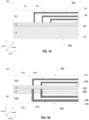
- FIGS. 1A-1C For convenience, if a collection of drawings designated with different letters are present (e.g., FIGS. 1A-1C ), such a collection may be referred to herein without the letters (e.g., as “ FIG. 1 "). Similarly, if a collection of reference numerals designated with different letters are present (e.g., 110A, 110B), such a collection may be referred to herein without the letters (e.g., as "110").
- Conductive vias 122 through the dielectric material may conductively connect conductive traces 120 to active circuitry in active region 112.
- Conductive vias 122 are orthogonal to conductive traces 120.
- Conductive traces 120 may extend up to surface 104 such that portions of conductive traces 120 are exposed on surface 104; such exposed portions may form bonding-portions 124.
- Conductive traces 120B and conductive vias 122B may be in metallization stack 102B.
- conductive traces 120A may be configured to route signals, whereas conductive traces 120B may be configured to route power and ground to active region 112.
- conductive traces 120B may be thicker than conductive traces 120A (i.e., conductive traces 120A may be thinner than conductive traces 120B).
- conductive traces 120A and conductive traces 120B may be configured to route signals, power, and ground without any differentiation between them. In such embodiments, conductive traces 120A and 120B may be of similar thickness.
- TSVs 202 through substrate 110 may enable conductive pathways between conductive traces 120A and 120B and/or active region 112 and conductive traces 120B.
- TSVs 202 may be through active region 112 (not shown).
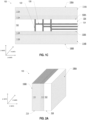
- FIG. 1C is a schematic cross-sectional view of yet another example IC die 100 according to some embodiments of the present disclosure.
- IC die 100 may include substrates 110A and 110B on either side of metallization stack 102.
- Substrate 110A may include surface 106A and substrate 110B may include surface 106B.
- Substrate 110A may share interface 108A with metallization stack 102 and substrate 110B may share interface 108B with metallization stack 102.
- Substrate 110A may include active region 112A and substrate 110B may include active region 112B. Active regions 112A and 112B may be adjacent to metallization stack 102 at respective interfaces 108A and 108B.
- Substrates 110A and 110B may have respective surfaces 114A and 114B that may be coplanar with surface 104.
- Metallization stack 102 may include a dielectric material and conductive traces 120 and conductive vias 122 through the dielectric material. Conductive vias 122 are orthogonal to conductive traces 120. The conductive traces 120 may be parallel to interfaces 108A and 108B such that conductive traces 120 are orthogonal to surface 104. Conductive vias 122 through the dielectric material may conductively connect conductive traces 120 to active circuitry in active regions 112A and 112B. One or more conductive vias 122 may further extend through the active regions 112A and/or 112B (not shown).
- FIG. 2A is a simplified perspective view of an IC die 100.
- FIG. 2A shows IC die 100 of FIG. 1A that has been rotated 90 degrees so that the surfaces 114 and 104 are positioned at the bottom and the surface 106 is positioned laterally.
- IC die 100 may include substrate 110, active region 112, and metallization stack 102.
- IC die 100 may have any suitable dimensions.
- FIG. 2B is a simplified perspective view of an IC die 100.
- FIG. 2B shows IC die 100 of FIG. 1B that has been rotated 90 degrees so that the surfaces 114, 104A, and 104B are positioned at the bottom and the surfaces 106A, 106B are positioned laterally.
- IC die 100 may include substrate 110, active region 112, and metallization stacks 102A, 102B.
- IC die 100 may have any suitable dimensions, including dimensions as described above with reference to FIG. 2A .
- Substrate 110 may have any suitable thickness (e.g., z-dimension).
- substrate 110 may have a thickness between less than 1 micron and 50 microns (e.g., between 0.25 microns and 5 microns, or between 20 microns and 50 microns). In some embodiments, substrate 110 may be almost entirely removed such that TSVs 202 may be very thin (e.g., having a thickness of less than 1 micron) and may provide direct contact to a transistor source/drain in active region 112.
- FIG. 2C is a simplified perspective view of an IC die 100.
- FIG. 2C shows IC die 100 of FIG. 1C that has been rotated 90 degrees so that the surfaces 114A, 114B, and 104 are positioned at the bottom and the surfaces 106A, 106B are positioned laterally.
- IC die 100 may include substrates 110A, 110B, active regions 112A, 112B, and metallization stack 102.
- FIGS. 3A-3D show simplified schematic cross-sections of various configurations of a microelectronic assembly 300 according to embodiments of the present disclosure.
- FIG. 3A shows microelectronic assembly 300 comprising a plurality of IC dies 100, for example, 100(1), 100(2) and 100(3) coupled to another IC die 302 by interconnects 304 such that surface 104 of any one of IC dies 100 is in direct contact with a surface 306 of IC die 302.
- surface 104 is orthogonal to interface 108 between active region 112 and metallization stack 102 of any one of IC dies 100.
- IC die 302 may include an interposer with conductive traces and/or TSVs to enable conductive coupling of IC die 100 with other IC dies and/or package substrates, and IC die 302 may not have any active circuitry therein. In other embodiments, IC die 302 may include active circuitry. In many embodiments, IC dies 100 may be conductively coupled by conductive pathways in IC die 302. For example, IC die 302 may include a network on chip, interconnecting compute circuitry of IC dies 100 together. In various embodiments, IC die 100 may be conductively coupled to IC die 302 by interconnects 304, which may include hybrid bonds. In such configuration, surface 114 of substrate 110 of IC dies 100 may be in direct contact with surface 306 of IC die 302.
- FIG. 3B is a schematic cross-sectional view of a detail of a particular one of interconnects 304 in microelectronic assembly 300.
- interconnect 304 may include, at an interface between surface 104 of IC die 100 and surface 306 of IC die 302, metal-metal bonds between bonding-portions 124 of IC die 100 and bond-pads 308 of IC die 302, and dielectric-dielectric bonds (e.g., oxide-oxide bonds) in dielectric materials 116 and 310 of IC dies 100 and 302, respectively.
- dielectric-dielectric bonds e.g., oxide-oxide bonds
- Bonding-portions 124 belonging to IC die 100 may bond with bond-pads 308 of IC die 302.
- bonding-portions 124 may include a portion of conductive traces 120 exposed on surface 104; bond-pads 308 may include conventional conductive structures electroplated on surface 306.
- Dielectric material 116 e.g., silicon oxide, silicon nitride, silicon oxynitride, etc.
- dielectric material 310 of IC die 302 is the same as dielectric material 116 of IC die 100.
- dielectric material 310 includes silicon oxide, silicon nitride, silicon carbonitride, and other such inorganic materials commonly used to fabricate semiconductor IC dies.
- the bonded metal and dielectric materials form interconnect 304, comprising hybrid bonds, providing electrical and mechanical coupling between IC die 100 and IC die 302.
- interconnects 304 may have a linear dimension of less than 5 microns and a pitch of less than 10 microns between adjacent interconnects.
- IC dies 100 may be coupled to IC die 302 such that metallization stack 102 of one of IC dies 100, for example, 100(1), may be in direct contact with substrate 110 of adjacent IC die 100, for example, 100(2).
- IC dies 100(1) and 100(2) may be bonded to each other, at least by oxide-oxide bonds.
- interconnects 304 comprising metal-metal bonds and oxide-oxide bonds as described in reference to FIG. 3B , may be present at the planar contact interface (e.g., respective surfaces 106A, 106B, as shown in FIG. 2A ) between IC dies 100(1) and 100(2).
- conductive contact between active region 112 of IC die 100(1) and 100(2) may be achieved through conductive traces 120 in IC die 100(1), interconnects 304 at the interface between IC dies 100(1) and 100(2), and TSVs 202 in IC die 100(2); in such embodiments, TSVs 202 are in conductive contact with interconnects 304 between IC dies 100(1) and 100(2).
- metallization stack 102 of IC dies 100(1) and 100(2) may be in contact in a front-to-front configuration.
- substrate 110 of IC dies 100(1) and 100(2) may be in contact in a back-to-back configuration.
- IC dies 100 may be arranged in mutually parallel rows such that a gap 312 exists between adjacent IC dies 100.
- Gap 312 may be uniform across microelectronic assembly 300 in some embodiments and may range approximately in the order of a few millimeters (e.g., less than 5 millimeters); in other embodiments, gap 312 may be non-uniform, with some IC dies 100 being closer to other than other IC dies 100.
- IC dies 100 may include circuitry that consumes electrical power and generates heat during operation.
- IC dies 100 may include compute circuitry of a microprocessor.
- Gap 312 may be configured for flow of a cooling fluid therethrough.
- the cooling fluid (not shown) may be air in some embodiments; in other embodiments, the cooling fluid may be a liquid coolant.
- IC dies 100 may include compute circuitry and VC circuitry
- IC die 302 may include a network on chip circuitry, conductively coupling the array of IC dies 100.
- IC dies 100(1), 100(2) may include memory circuitry
- IC die 100(3) may include compute circuitry and VC circuitry
- IC die 302 may include a network on chip circuitry, conductively coupling the array of IC dies 100.
- IC die 100(1) may include capacitors and/or inductors
- IC die 100(2) may include compute circuitry and VC circuitry
- IC die 100(3) may include memory circuitry
- IC die 302 may include a network on chip circuitry, conductively coupling the array of IC dies 100.
- some IC dies 100 may include graphics processing circuitry and other IC dies may include compute circuitry and VC circuitry
- IC die 302 may include VC circuitry. Any suitable configuration of circuitry may be provided in microelectronic assembly 300 among IC dies 100 and IC die 302 as desired and based on particular needs.
- FIG. 3C is a schematic cross-sectional view of a portion 313 of microelectronic assembly 300 of FIG. 3A according to some embodiments of the present disclosure.
- IC die 302 may include a metallization stack 314 attached to a substrate 316 having an active region 318.
- Substrate 316 is attached to metallization stack 314 along another interface 320 that is parallel to surface 306.
- active region 318 includes active circuitry (not shown), including transistors and diodes. Active region 318 may be proximate to interface 320 in such embodiments. In some embodiments, active region 318 may be absent.
- Metallization stack 314 may further include conductive pathways (e.g., conductive traces 322 and conductive vias 324) in a dielectric material.
- the dielectric material of metallization stack 314 is the dielectric material 310 in FIG. 3B .
- Conductive traces 322 may be coupled by conductive vias 324 to bond-pads 308.
- FIG. 3D is a schematic cross-sectional view of portion 313 of microelectronic assembly 300 of FIG. 3A according to some embodiments of the present disclosure.
- IC die 302 may be substantially similar to the embodiment of FIG. 3C , except that it is inverted (e.g., turned upside-down), so that substrate 316 is proximate to surface 104 of IC die 100.
- IC die 302 may include an interface layer 326 (e.g., bonding layer) on a side of substrate 316 opposite to metallization stack 314.
- Interface layer 326 includes bond-pads 308 having a dielectric material between bond-pads 308 (e.g., surrounding the bond-pads 308), such that interconnects 304 are formed from metal-metal bonds of bonding-portions 124 and bond-pads 308 and oxide-oxide bonds of dielectric materials of the substrate 110 of IC die 100(3) and of the interface layer 326 of IC die 302.
- the dielectric material of the interface layer 326 is a same material as the dielectric material 310 in FIG. 3B .
- dielectric material of the interface layer 326 is a same material as the dielectric material 116 of IC die 100 in FIG. 3B .
- the dielectric material of the interface layer 326 may include silicon oxide, silicon nitride, silicon carbonitride, or other such inorganic materials commonly used to fabricate semiconductor IC dies.
- IC die 302 may further include TSVs 330 in substrate 316 between interface layer 326 and metallization stack 314. TSVs 330 may enable electrical connectivity between interconnects 304 and active region 318 and/or conductive traces 322 in IC die 302.
- FIG. 3E is a schematic cross-sectional view of microelectronic assembly 300 according to some embodiments of the present disclosure.
- the embodiment shown in the figure is similar to that in FIG. 3A , except that IC die 100(1) is coupled end-to-end with IC die 100(2) to form a stack of IC dies.
- any single IC die 100 of FIG. 3A is replaced in the embodiment shown in FIG. 3E by corresponding stacks of IC dies 100 coupled end-to-end as described further.
- IC dies 100(1) and 100(2) may be in direct contact end-to-end along surface 103, opposite to surface 104 of IC die 100(1).
- Conductive traces 120(1) of IC die 100(1) may be conductively coupled to conductive traces 120(2) of IC die 100(2) through interconnects 304 on surface 103.
- Substrates 110(1) and 110(2) may be in direct contact on interface 107.
- substrates 110(1) and 110(2) may be bonded by oxide-oxide bonds along common interface 107.
- FIG. 4 is a simplified perspective view of an example microelectronic assembly 300 including IC dies 100 of FIG. 2A .
- a plurality of IC dies 100 e.g., IC dies 100(1), 100(2), 100(3), and 100(4)
- the plurality of IC dies 100 may be coupled to IC die 302 by any suitable interconnects, for example, interconnects 304 in FIG. 3 .
- IC die 302 may be large-sized, for example, as large as a conventional reticle, which can be approximately 858 square millimeters (mm 2 ) in footprint area.
- FIG. 4 shows IC dies 100 having metallization stacks 102(1), 102(2), 102(3), 102(4) facing away from each other, in some embodiments, one or more of IC dies 100 may have one or more metallization stacks 102 facing each other.
- IC dies 100(2), 100(3), and 100(4) may be stacked vertically and bonded together at respective surfaces (e.g., surfaces 106A, 106B, as shown in FIG.
- the stacked and bonded IC dies 100 may be rotated 90 degrees and electrically coupled at surface 104 to IC die 302.
- the plurality of IC dies 100 may be coupled to IC die 302 by any suitable interconnects, for example, interconnects 304 in FIG. 3 .
- Stacking and bonding IC dies 100 prior to coupling with IC die 302 may allow for IC dies 100 to be more easily handled during assembly operations. Any suitable number of IC dies 100 may be stacked and bonded together, for example, between 2 and 100 IC dies.
- FIG. 4 shows IC dies 100 having a particular stacked arrangement (e.g., all facing a same direction), in some embodiments, one or more of IC dies 100 may have a different stacked arrangement (e.g., one or more IC dies 100 may be inverted to face an opposite direction). Further, although FIG. 4 includes IC dies 100 of FIG. 1A , a stack of IC dies 100 may include any IC dies 100 of FIGS. 1A-1C .
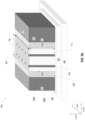
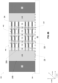
- FIG. 5A is a perspective view of IC package 500 according to some embodiments of the present disclosure.
- the embodiment shown in the figure includes IC die 100A electrically coupled at a lateral surface 104 to a surface 306 of IC die 302 and a microelectronic assembly 400 including a plurality of IC die 113 having TSVs 402 and electrically coupled at respective top and bottom surfaces (e.g., stacked in a conventional pancake-style), and the bottommost IC die 113 is electrically coupled to surface 306 of IC die 302.
- a first surface and an opposing second surface, or a top surface and a bottom surface of IC die 100, 113, 115 e.g., as shown in FIG.
- Microelectronic assembly 400 may further include a redistribution layer (RDL) 182 (e.g., as shown in more detail in FIG. 5B ) between IC die 113.
- IC package 500 may further include dummy silicon 111 and a package substrate 404 electrically coupled to IC die 302.
- Microelectronic assembly 400 may be centrally located on (e.g., in a middle portion of) IC die 302 and IC die 100A may be positioned at opposite sides of microelectronic assembly 400. Dummy silicon 111 may be positioned at the other sides of IC die 100A. In some embodiments, IC die 100A may be positioned at one side of microelectronic assembly 400 or may be positioned at more than two sides of microelectronic assembly 400, for example, at three sides or four sides (not shown) of microelectronic assembly 400. In some embodiments, IC die 100A may include compute circuitry and IC die 113 may include memory circuitry, such as Static Random Access Memory (SRAM) or Dynamic Random Access Memory (DRAM).
- SRAM Static Random Access Memory
- DRAM Dynamic Random Access Memory
- IC package 500 of FIG. 5A may provide increased power delivery through memory cube (e.g., microelectronic assembly 400), as compared to conventional IC packages.
- microelectronic assembly 400 also may be referred to as a "memory cube.”
- Microelectronic assembly 400 may have any suitable dimensions. For example, microelectronic assembly 400 may have a height 191 between 3 millimeters (mm) and 5 mm, a width 193 between 10 mm and 20 mm, and a length 195 between 1 mm and 2 mm.
- Microelectronic assembly 400 may include a between 30 and 40 stacked IC die 113 with TSVs 402, where TSVs 402 are part of a power delivery network.
- TSVs 402 may have any suitable dimensions for power delivery, for example, TSVs 402 may include between 80 microns and 100 microns of total metal (e.g., copper) to deliver a required amount of current (e.g., approximately 100 amperes) to each IC die 100A. In some embodiments, TSVs 402 may have a diameter between 4 microns and 10 microns.
- TSVs 402 may include between 80 microns and 100 microns of total metal (e.g., copper) to deliver a required amount of current (e.g., approximately 100 amperes) to each IC die 100A.
- TSVs 402 may have a diameter between 4 microns and 10 microns.
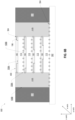
- FIG. 5B is a cross-sectional view of IC package 500 according to some embodiments of the present disclosure.
- FIG. 5B illustrates IC package 500 of FIG. 5A and further includes a circuit board 131.
- IC package 500 may include IC die 100A, dummy silicon 111, and microelectronic assembly 400 electrically coupled to a surface 306 of IC die 302 by interconnects 304, IC die 302 may be electrically coupled to package substrate 404 by interconnects 352, and package substrate 404 may be electrically coupled to a circuit board 131 by interconnects 150.
- Microelectronic assembly 400 may include a plurality of IC die 113 electrically coupled at respective top and bottom surfaces (e.g., surfaces 106A, 106B) with an RDL 182 between adjacent IC die 113.
- RDL 182 may include conductive pathways 196 and conductive vias 198.
- Conductive vias 198 may couple with TSVs in individual IC die 113 to form TSVs 402 that extend through microelectronic assembly 400.
- Conductive pathways 196 enable lateral routing between TSVs 402 and IC die 100A by interconnects 304 at surface 106 of IC die 100A.
- Conductive vias 198 in RDL 182 are shown as lighter and having dotted lines as compared to TSVs 402 in IC die 113 to allow conductive pathways 196 to be shown more clearly.
- An RDL 182 may include an insulating material (e.g., a dielectric material formed in multiple layers, as known in the art) and one or more conductive pathways 196 including conductive vias 198 through the dielectric material, as shown.
- the conductive vias 198 may be electrically coupled to TSVs 402 to form conductive vias that extend through microelectronic assembly 400.
- the conductive pathways 196 may electrically couple to the conductive vias 198 for power delivery to IC die 100A.
- the insulating material of the RDL 182 may be composed of dielectric materials, bismaleimide triazine (BT) resin, polyimide materials, epoxy materials (e.g., glass reinforced epoxy matrix materials, epoxy build-up films, or the like), mold materials, oxide-based materials (e.g., silicon dioxide or spin on oxide), or low-k and ultra low-k dielectric (e.g., carbon-doped dielectrics, fluorine-doped dielectrics, porous dielectrics, and organic polymeric dielectrics).
- RDL 182 may have any suitable thickness, for example, in some embodiments, the RDL 182 may have a thickness between 2 microns and 4 microns.
- RDL 182 may be manufactured using any suitable technique, such as a PCB technique or a redistribution layer technique.
- a set of interconnects 352 may include solder (e.g., solder bumps or balls that are subject to a thermal reflow to form the interconnects 352).
- the interconnects 352 that include solder may include any appropriate solder material, such as lead/tin, tin/bismuth, eutectic tin/silver, ternary tin/silver/copper, eutectic tin/copper, tin/nickel/copper, tin/bismuth/copper, tin/indium/copper, tin/zinc/indium/bismuth, or other alloys.
- the conductive particles may include nickel-coated gold or silver-coated copper that is in turn coated with a polymer.
- the conductive particles may include nickel.
- an anisotropic conductive material When an anisotropic conductive material is uncompressed, there may be no conductive pathway from one side of the material to the other. However, when the anisotropic conductive material is adequately compressed (e.g., by conductive contacts on either side of the anisotropic conductive material), the conductive materials near the region of compression may contact each other so as to form a conductive pathway from one side of the film to the other in the region of compression.
- the IC package 500 may further include a circuit board 131.
- the circuit board 131 may be a motherboard, for example, and may have other components attached to it.
- the circuit board 131 may include conductive pathways and other conductive contacts for routing power, ground, and signals through the circuit board, as known in the art.
- the interconnects 150 may be any suitable interconnects, including solder balls for a ball grid array arrangement, pins in a pin grid array arrangement or lands in a land grid array arrangement.
- a set of interconnects 150 may include solder (e.g., solder bumps or balls that are subject to a thermal reflow to form the interconnects 150).
- the interconnects 150 disclosed herein may have a pitch between about 900 microns and 1.2 mm. In some embodiments, the interconnects 150 may not couple the package substrate 404 to a circuit board 131, but may instead couple the package substrate 404 to another IC package, an interposer, or any other suitable component.
- one side of an interconnect may include a metal pillar (e.g., a copper pillar), and the other side of the interconnect may include a metal contact (e.g., a copper contact) recessed in a dielectric.
- a metal-to-metal interconnect e.g., a copper-to-copper interconnect
- a noble metal e.g., gold
- a metal whose oxides are conductive e.g., silver
- a metal-to-metal interconnect may include metal nanostructures (e.g., nanorods) that may have a reduced melting point.
- Metal-to-metal interconnects may be capable of reliably conducting a higher current than other types of interconnects; for example, some solder interconnects may form brittle intermetallic compounds when current flows, and the maximum current provided through such interconnects may be constrained to mitigate mechanical failure.
- a thin cap of solder may be used in a metal-to-metal interconnect to accommodate planarity, and this solder may become an intermetallic compound during processing.
- the solder used in some of the interconnects may have a higher melting point than the solder included in other of the interconnects. For example, when the interconnects in an IC package are formed before other interconnects, solder-based interconnects formed first may use a higher-temperature solder (e.g., with a melting point above 200 degrees Celsius), while the interconnects formed second may use a lower-temperature solder (e.g., with a melting point below 200 degrees Celsius).
- a higher-temperature solder may include tin; tin and gold; or tin, silver, and copper (e.g., 96.5 % tin, 3% silver, and 0.5% copper).
- a lower-temperature solder may include tin and bismuth (e.g., eutectic tin bismuth), tin, silver, bismuth, indium, indium and tin, or gallium.
- IC package 500 may also include an underfill material 127.
- the underfill material 127 may extend between a bottom surface of IC die 302 and a top surface of the package substrate 404 around the associated interconnects 352 and/or between the bottom surface of the package substrate 404 and the top surface of the circuit board 131 around the associated interconnects 150.
- the underfill material 127 may be an insulating material, such as an appropriate epoxy material.
- the underfill material 127 may include a capillary underfill, non-conductive film (NCF), or molded underfill.
- the underfill material 127 may include an epoxy flux that assists with soldering IC die 302 to the package substrate 404 when forming the interconnects 352 or soldering package substrate 404 to circuit board 131 forming interconnects 150, and then polymerizes and encapsulates the respective interconnects 352, 150.
- the underfill material 127 may be selected to have a coefficient of thermal expansion (CTE) that may mitigate or minimize the stress between IC die 302 and the package substrate 404 arising from uneven thermal expansion in the IC package 500.
- CTE coefficient of thermal expansion
- FIG. 6A is a schematic perspective view of another example IC package 500 according to some embodiments of the present disclosure.
- the embodiment shown in the figure is similar to that of FIG. 5A , except that IC package 500 includes IC die 100B and microelectronic assembly 400 does not include TSVs 402 shown in FIG. 5 .
- IC die 100B may be electrically coupled at a lateral surface 104 to IC die 302.
- IC die 302 may include compute circuitry.
- FIG. 6B is a cross-sectional view of IC package 500 of FIG. 6A according to some embodiments of the present disclosure.
- IC package 500 may include a microelectronic assembly 400, IC die 100B, and dummy silicon 111 electrically coupled to surface 306 of IC die 302 by interconnects 304.
- IC die 100B may be selected from one or more embodiments shown at least in FIGS.
- FIG. 6C is a schematic perspective view of another example IC package 500 according to some embodiments of the present disclosure.
- the embodiment shown in the figure is similar to that of FIG. 6A , except that IC package 500 does not include dummy silicon 111 and microelectronic assembly 400 further includes IC die 115.
- IC package 500 may further include dummy silicon 111 (not shown).
- FIG. 6D is a cross-sectional view of IC package 500 of FIG. 6C according to some embodiments of the present disclosure.
- IC package 500 may include a microelectronic assembly 400 and a plurality of IC die 100B on opposite sides of microelectronic assembly 400.
- the plurality of IC die 100B and microelectronic assembly 400 may be electrically coupled to surface 306 of IC die 302 by interconnects 304.
- the plurality of IC die 100B may be selected from one or more embodiments shown at least in FIGS.
- RDL 182 may include conductive pathways 196 electrically coupling IC die 113, 115 to IC die 100B by interconnects 304 (e.g., interconnects 304 at the interface along the z-axis between IC die 100B and IC die 113, 115).
- IC die 115 is a top IC die and/or a bottom IC die in microelectronic assembly 400, as shown.
- IC die 115 may be stacked between IC die 113.
- Microelectronic assembly 400 may include any suitable number and arrangement of IC die 113, 115, for example, microelectronic assembly 400 may include between 1 and 2 IC die 115 and between 30 and 38 IC die 113.
- FIG. 6E is a schematic perspective view of another example IC package 500 according to some embodiments of the present disclosure.
- the embodiment shown in the figure is similar to that of FIG. 6C , except that IC package 500 further includes dummy silicon 111 between IC die 100B and a plurality of IC die 100B at four sides of microelectronic assembly 400.
- FIG. 6 shows a particular number and arrangement of IC die 100B and microelectronic assembly 400
- IC package 500 may have any suitable number and arrangement of IC die 100B and microelectronic assembly 400, including IC die 113, IC die 115, and dummy silicon 111.
- FIG. 7A is a schematic perspective view of another example IC package 500 according to some embodiments of the present disclosure.
- the embodiment shown in the figure is similar to that of FIG. 6A , except that IC package 500 has multiple layers 105 of stacked microelectronic assembly 400, stacked IC die 100C, and stacked dummy silicon 111.
- first layer 105(1) may include microelectronic assembly 400(1), IC die 100C(1), and dummy silicon 111(1)
- second layer 105(2) may include microelectronic assembly 400(2), IC die 100C(2), and dummy silicon 111(2), where the second layer 105(2) is on the first layer 105(1).
- IC die 100C(1) may be electrically coupled at a lateral surface 104(1) to IC die 302.
- IC die 100C may be selected from one or more of embodiments shown at least in FIGS. 1A-1C , and may include voltage regulator (VR) circuitry.
- VR circuitry may include electronic components and circuitry for maintaining a constant voltage, for example, a voltage input, a voltage output, an input capacitor, an output capacitor, an inductor, a switching transistor and/or a diode, and a control circuit having a plurality of transistors to perform voltage regulation and to control the switching transistor and/or diode.
- VR circuitry may include various voltage rails configured to provide current at correspondingly different voltages.
- VR circuitry may be fabricated using processes particularly suitable for voltage regulator circuitry, such as a special silicon process, or processes using III-V devices, such as gallium nitride or silicon carbide, for example, to support improved power conversion.
- IC package 500 of FIG. 7 may provide increased power delivery as compared to conventional IC packages.
- IC package 500 of FIG. 7 with IC die 100C having VR circuitry enables a high voltage input (e.g., a voltage input of approximately 5V) with reduced current drop along the z-direction (e.g., top to bottom of IC package 500).
- FIG. 7B is a cross-sectional view of IC package 500 of FIG. 7A according to some embodiments of the present disclosure.
- IC package 500 may include a first layer 105(1) having microelectronic assembly 400(1), IC die 100C(1), and dummy silicon 111(1) electrically coupled to surface 306 of IC die 302 by interconnects 304.
- IC package 500 may further include second layer 105(2) on first layer 105(1) and second layer 105(2) may include microelectronic assembly 400(2), IC die 100C(2), and dummy silicon 111(2).
- IC die 100C(2) may be stacked on IC die 100C(1) and coupled by interconnects 304 at surface 103 and bonded at interface 107 by oxide-to-oxide bonds, as described above with reference to FIG. 3E .
- Dummy silicon 111(1) may be bonded to dummy silicon 111(2) using any suitable process, including interconnects 304, as shown, fusion bonding, or diffusion bonding, as described above with reference to FIG. 5 .
- Microelectronic assembly 400 may include a plurality of IC die 113 electrically coupled at a respective top and bottom surfaces 106A, 106B with RDL 182 in between IC die 113.
- RDL 182 may include conductive pathways 196 electrically coupling IC die 113 to IC die 100C by interconnects 304 at respective surfaces 106A, 106B of IC die 100C.
- IC die 113 may be electrically coupled to IC die 302 through IC die 100C.
- FIG. 7 shows a particular number and arrangement of microelectronic assembly 400, IC die 100C, and dummy silicon 111
- IC package 500 may have any suitable number and arrangement of microelectronic assembly 400, IC die 100C, and dummy silicon 111. Further, although FIG. 7 shows IC package 500 having a particular number of layers, IC package 500 may have any suitable number of layers, including more than two layers.
- conductive pathways 196 in RDL 182 are electrically coupled at surface 804 to IC 302 by interconnects 304 and TSVs 402 are coupled to IC die 100B at respective surfaces 106A, 106B by interconnects 304.
- IC die 100B may be selected from one or more embodiments shown at least in FIGS. 1A-1C and may include active circuitry for delivering power to IC die 113 or may not include active circuitry.
- Conductive pathways 196 in RDL 182 may be configured to transmit signals and TSVs 402 may be configured to deliver power, such that signal delivery is separate from power delivery.
- IC package 500 of FIG. 8B may reduce bandwidth crowding issues with power and signaling as compared to conventional IC packages by separating out power delivery and signal transmission.
- any of the features discussed with reference to any of FIGS. 1-8 herein may be combined with any other features to form a package with one or more microelectronic assemblies and one or more IC dies as described herein, for example, to form a modified IC package 500 or a modified microelectronic assembly 400.
- Some such combinations are described above, but, in various embodiments, further combinations and modifications are possible.
- Various different embodiments described in different figures may be combined suitably based on particular needs within the broad scope of the embodiments.
- FIGS. 9-11 illustrate various examples of packages, assemblies, and devices that may be used with or include any of the IC packages as disclosed herein.
- FIG. 9 is a side, cross-sectional view of an example IC package 2200 that may include components in accordance with any of the embodiments disclosed herein.
- the IC package 2200 may be a SiP.
- package substrate 2252 may be formed of an insulator (e.g., a ceramic, a buildup film, an epoxy film having filler particles therein, etc.), and may have conductive pathways extending through the insulator between first face 2272 and second face 2274, or between different locations on first face 2272, and/or between different locations on second face 2274. These conductive pathways may take the form of any of the interconnect structures comprising lines and/or vias.
- an insulator e.g., a ceramic, a buildup film, an epoxy film having filler particles therein, etc.
- Package substrate 2252 may include conductive contacts 2263 that are coupled to conductive pathway 2262 through package substrate 2252, allowing circuitry within dies 2256 and/or interposer 2257 to electrically couple to various ones of conductive contacts 2264 (or to other devices included in package substrate 2252, not shown).
- IC package 2200 may include interposer 2257 coupled to package substrate 2252 via conductive contacts 2261 of interposer 2257, first-level interconnects 2265, and conductive contacts 2263 of package substrate 2252.
- First-level interconnects 2265 illustrated in the figure are solder bumps, but any suitable first-level interconnects 2265 may be used, such as solder bumps, solder posts, or bond wires.
- IC package 2200 may include one or more dies 2256 coupled to interposer 2257 via conductive contacts 2254 of dies 2256, first-level interconnects 2258, and conductive contacts 2260 of interposer 2257.
- Conductive contacts 2260 may be coupled to conductive pathways (not shown) through interposer 2257, allowing circuitry within dies 2256 to electrically couple to various ones of conductive contacts 2261 (or to other devices included in interposer 2257, not shown).
- First-level interconnects 2258 illustrated in the figure are solder bumps, but any suitable first-level interconnects 2258 may be used, such as solder bumps, solder posts, or bond wires.
- a "conductive contact” may refer to a portion of electrically conductive material (e.g., metal) serving as an interface between different components; conductive contacts may be recessed in, flush with, or extending away from a surface of a component, and may take any suitable form (e.g., a conductive pad or socket).
- electrically conductive material e.g., metal
- underfill material 2266 may be disposed between package substrate 2252 and interposer 2257 around first-level interconnects 2265, and mold 2268 may be disposed around dies 2256 and interposer 2257 and in contact with package substrate 2252. In some embodiments, underfill material 2266 may be the same as mold 2268. Example materials that may be used for underfill material 2266 and mold 2268 are epoxies as suitable. Second-level interconnects 2270 may be coupled to conductive contacts 2264.
- Second-level interconnects 2270 illustrated in the figure are solder balls (e.g., for a ball grid array (BGA) arrangement), but any suitable second-level interconnects 2270 may be used (e.g., pins in a pin grid array arrangement or lands in a land grid array arrangement). Second-level interconnects 2270 may be used to couple IC package 2200 to another component, such as a circuit board (e.g., a motherboard), an interposer, or another IC package, as known in the art and as discussed below with reference to FIG. 10 .
- BGA ball grid array
- any of dies 2256 may be microelectronic assembly 300 as described herein.
- IC package 2200 may be referred to as a multi-chip package (MCP).
- Dies 2256 may include circuitry to perform any desired functionality.
- one or more of dies 2256 may be logic dies (e.g., silicon-based dies), one or more of dies 2256 may be memory dies (e.g., HBM), etc.
- any of dies 2256 may be implemented as discussed with reference to any of the previous figures. In some embodiments, at least some of dies 2256 may not include implementations as described herein.
- IC package 2200 illustrated in the figure is a flip-chip package, other package architectures may be used.
- IC package 2200 may be a BGA package, such as an embedded wafer-level ball grid array (eWLB) package.
- IC package 2200 may be a wafer-level chip scale package (WLCSP) or a panel fan-out (FO) package.
- WLCSP wafer-level chip scale package
- FO panel fan-out
- IC package 2200 may include any desired number of dies 2256.
- IC package 2200 may include additional passive components, such as surface-mount resistors, capacitors, and inductors disposed over first face 2272 or second face 2274 of package substrate 2252, or on either face of interposer 2257. More generally, IC package 2200 may include any other active or passive components known in the art.
- no interposer 2257 may be included in IC package 2200; instead, dies 2256 may be coupled directly to conductive contacts 2263 at first face 2272 by first-level interconnects 2265.
- FIG. 10 is a cross-sectional side view of an IC device assembly 2300 that may include components, in accordance with any of the embodiments disclosed herein.
- IC device assembly 2300 includes a number of components disposed over a circuit board 2302 (which may be, e.g., a motherboard).
- IC device assembly 2300 includes components disposed over a first face 2340 of circuit board 2302 and an opposing second face 2342 of circuit board 2302; generally, components may be disposed over one or both faces 2340 and 2342.
- any suitable ones of the components of IC device assembly 2300 may include any of the one or more microelectronic assembly 300 in accordance with any of the embodiments disclosed herein; e.g., any of the IC packages discussed below with reference to IC device assembly 2300 may take the form of any of the embodiments of IC package 2200 discussed above with reference to FIG. 9 .
- circuit board 2302 may be a PCB including multiple metal layers separated from one another by layers of insulator and interconnected by electrically conductive vias. Any one or more of the metal layers may be formed in a desired circuit pattern to route electrical signals (optionally in conjunction with other metal layers) between the components coupled to circuit board 2302. In other embodiments, circuit board 2302 may be a non-PCB package substrate.
- IC device assembly 2300 may include a package-on-interposer structure 2336 coupled to first face 2340 of circuit board 2302 by coupling components 2316.
- Coupling components 2316 may electrically and mechanically couple package-on-interposer structure 2336 to circuit board 2302, and may include solder balls (as shown), male and female portions of a socket, an adhesive, an underfill material, and/or any other suitable electrical and/or mechanical coupling structure.
- Package-on-interposer structure 2336 may include IC package 2320 coupled to interposer 2304 by coupling components 2318. Coupling components 2318 may take any suitable form depending on desired functionalities, such as the forms discussed above with reference to coupling components 2316.
- IC package 2320 may be or include IC package 2200, e.g., as described above with reference to FIG. 9 .
- IC package 2320 may include at least one microelectronic assembly 300 as described herein. Microelectronic assembly 300 is not specifically shown in the figure in order to not clutter the drawing.
- Interposer 2304 may be formed of an epoxy resin, a fiberglass-reinforced epoxy resin, a ceramic material, or a polymer material such as polyimide. In some implementations, interposer 2304 may be formed of alternate rigid or flexible materials that may include the same materials described above for use in a semiconductor substrate, such as silicon, germanium, and other group III-V and group IV materials. Interposer 2304 may include metal interconnects 2308 and vias 2310, including but not limited to TSVs 2306. Interposer 2304 may further include embedded devices 2314, including both passive and active devices. Such devices may include, but are not limited to, capacitors, decoupling capacitors, resistors, inductors, fuses, diodes, transformers, sensors, ESD devices, and memory devices.
- More complex devices such as radio frequency (RF) devices, power amplifiers, power management devices, antennas, arrays, sensors, and microelectromechanical systems (MEMS) devices may also be formed on interposer 2304.
- RF radio frequency
- MEMS microelectromechanical systems
- Package-on-interposer structure 2336 may take the form of any of the package-on-interposer structures known in the art.
- IC device assembly 2300 may include an IC package 2324 coupled to first face 2340 of circuit board 2302 by coupling components 2322.
- Coupling components 2322 may take the form of any of the embodiments discussed above with reference to coupling components 2316
- IC package 2324 may take the form of any of the embodiments discussed above with reference to IC package 2320.
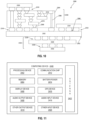
- computing device 2400 A number of components are illustrated in the figure as included in computing device 2400, but any one or more of these components may be omitted or duplicated, as suitable for the application. In some embodiments, some or all of the components included in computing device 2400 may be attached to one or more motherboards. In some embodiments, some or all of these components are fabricated onto a single system-on-chip (SOC) die.
- SOC system-on-chip
- Computing device 2400 may include a processing device 2402 (e.g., one or more processing devices).
- processing device e.g., one or more processing devices.
- processing device may refer to any device or portion of a device that processes electronic data from registers and/or memory to transform that electronic data into other electronic data that may be stored in registers and/or memory.
- Processing device 2402 may include one or more DSPs, ASICs, CPUs, GPUs, cryptoprocessors (specialized processors that execute cryptographic algorithms within hardware), server processors, or any other suitable processing devices.
- Computing device 2400 may include a memory 2404, which may itself include one or more memory devices such as volatile memory (e.g., dynamic random access memory (DRAM)), nonvolatile memory (e.g., read-only memory (ROM)), flash memory, solid-state memory, and/or a hard drive.
- volatile memory e.g., dynamic random access memory (DRAM)
- nonvolatile memory e.g., read-only memory (ROM)
- flash memory solid-state memory
- solid-state memory solid-state memory
- hard drive e.g., solid-state memory, and/or a hard drive.
- memory 2404 may include memory that shares a die with processing device 2402. This memory may be used as cache memory and may include embedded dynamic random access memory (eDRAM) or spin transfer torque magnetic random access memory (STT-MRAM).
- eDRAM embedded dynamic random access memory
- STT-MRAM spin transfer torque magnetic random access memory
- computing device 2400 may include a communication chip 2412 (e.g., one or more communication chips).
- communication chip 2412 may be configured for managing wireless communications for the transfer of data to and from computing device 2400.
- wireless and its derivatives may be used to describe circuits, devices, systems, methods, techniques, communications channels, etc., that may communicate data through the use of modulated electromagnetic radiation through a nonsolid medium. The term does not imply that the associated devices do not contain any wires, although in some embodiments they might not.
- Communication chip 2412 may implement any of a number of wireless standards or protocols, including but not limited to Institute for Electrical and Electronic Engineers (IEEE) standards including Wi-Fi (IEEE 802.11 family), IEEE 802.16 standards (e.g., IEEE 802.16-2005 Amendment), LTE project along with any amendments, updates, and/or revisions (e.g., advanced LTE project, ultramobile broadband (UMB) project (also referred to as "3GPP2”), etc.).
- IEEE 802.16 compatible Broadband Wireless Access (BWA) networks are generally referred to as WiMAX networks, an acronym that stands for Worldwide Interoperability for Microwave Access, which is a certification mark for products that pass conformity and interoperability tests for the IEEE 802.16 standards.
- the communication chip 2412 may operate in accordance with a Global System for Mobile Communication (GSM), General Packet Radio Service (GPRS), Universal Mobile Telecommunications System (UMTS), High-Speed Packet Access (HSPA), Evolved HSPA (E-HSPA), or LTE network.
- GSM Global System for Mobile Communication
- GPRS General Packet Radio Service
- UMTS Universal Mobile Telecommunications System
- High-Speed Packet Access HSPA
- E-HSPA Evolved HSPA
- LTE LTE network.
- the communication chip 2412 may operate in accordance with Enhanced Data for GSM Evolution (EDGE), GSM EDGE Radio Access Network (GERAN), Universal Terrestrial Radio Access Network (UTRAN), or Evolved UTRAN (E-UTRAN).
- EDGE Enhanced Data for GSM Evolution
- GERAN GSM EDGE Radio Access Network
- UTRAN Universal Terrestrial Radio Access Network
- E-UTRAN Evolved UTRAN
- Computing device 2400 may include battery/power circuitry 2414.
- Battery/power circuitry 2414 may include one or more energy storage devices (e.g., batteries or capacitors) and/or circuitry for coupling components of computing device 2400 to an energy source separate from computing device 2400 (e.g., AC line power).
- Computing device 2400 may include audio output device 2408 (or corresponding interface circuitry, as discussed above). Audio output device 2408 may include any device that generates an audible indicator, such as speakers, headsets, or earbuds, for example.
- Computing device 2400 may include audio input device 2418 (or corresponding interface circuitry, as discussed above). Audio input device 2418 may include any device that generates a signal representative of a sound, such as microphones, microphone arrays, or digital instruments (e.g., instruments having a musical instrument digital interface (MIDI) output).
- MIDI musical instrument digital interface
- Computing device 2400 may include a GPS device 2416 (or corresponding interface circuitry, as discussed above). GPS device 2416 may be in communication with a satellite-based system and may receive a location of computing device 2400, as known in the art.
- Computing device 2400 may include other output device 2410 (or corresponding interface circuitry, as discussed above).
- Examples of other output device 2410 may include an audio codec, a video codec, a printer, a wired or wireless transmitter for providing information to other devices, or an additional storage device.
- Computing device 2400 may include other input device 2420 (or corresponding interface circuitry, as discussed above).
- Examples of other input device 2420 may include an accelerometer, a gyroscope, a compass, an image capture device, a keyboard, a cursor control device such as a mouse, a stylus, a touchpad, a bar code reader, a Quick Response (QR) code reader, any sensor, or a radio frequency identification (RFID) reader.
- RFID radio frequency identification
- Computing device 2400 may have any desired form factor, such as a handheld or mobile computing device (e.g., a cell phone, a smart phone, a mobile internet device, a music player, a tablet computer, a laptop computer, a netbook computer, an ultrabook computer, a personal digital assistant (PDA), an ultramobile personal computer, etc.), a desktop computing device, a server or other networked computing component, a printer, a scanner, a monitor, a set-top box, an entertainment control unit, a vehicle control unit, a digital camera, a digital video recorder, or a wearable computing device.
- computing device 2400 may be any other electronic device that processes data.
- Example 1 is an integrated circuit (IC) package, including a microelectronic assembly, the microelectronic assembly including at least two first IC die including memory circuitry, the at least two first IC die having a first surface and a second surface opposite the first surface, wherein the at least two first IC die are stacked and electrically coupled at respective first and second surfaces; and at least one redistribution layer (RDL) between the at least two first IC die, wherein the RDL includes conductive pathways; a second IC die having a first surface, a second surface opposite the first surface, a third surface orthogonal to the first and second surfaces, and a conductive trace that is parallel to the first and second surfaces and exposed at the third surface, wherein the first surface of the second IC die is electrically coupled to some of the conductive pathways in the at least one RDL; and a third IC die having a surface, wherein the second surface of a bottom die in the stack of the at least two first IC die is electrically coupled to the surface of the third IC
- Example 2 may include the subject matter of Example 1, and may further include a dummy silicon at the second surface of the second IC die and coupled to the surface of the third IC die.
- Example 3 may include the subject matter of Example 1 or 2, and may further specify that the second IC die is one of a plurality of second IC die.
- Example 4 may include the subject matter of Example 3, and may further specify that at least one of the at least two first IC die includes compute circuitry.
- Example 5 may include the subject matter of Example 3, and may further specify that the plurality of second IC die are bonded together at respective first and second surfaces.
- Example 6 may include the subject matter of Example 5, and may further include dummy silicon between individual ones of the plurality of second IC die that are bonded together.
- Example 7 may include the subject matter of any of Examples 1-3, and may further specify that the third IC die includes compute circuitry.
- Example 8 may include the subject matter of any of Examples 1-3, and may further specify that the microelectronic assembly further includes conductive vias through the at least two first IC die and the RDL, wherein the conductive vias are electrically coupled to the surface of the third IC die.
- Example 9 may include the subject matter of any of Examples 1-8, and may further specify that the surface of the third IC die is a first surface and the third further includes a second surface opposite the first surface, and the IC package and may further include a package substrate electrically coupled to the second surface of the third IC die.
- Example 10 may include the subject matter of any of Examples 1-9, and may further specify that the first IC die and the second IC die are electrically coupled to the third IC die by metal-metal bonds and dielectric-dielectric bonds.
- Example 11 is an integrated circuit (IC) package, including a first layer, the first layer including a plurality of first IC die including memory circuitry, each of the plurality of first IC die having a first surface and a second surface opposite the first surface, wherein the plurality of first IC die are stacked and coupled at respective first and second surfaces with at least one first redistribution layer (RDL) between individual ones of the plurality of first IC die, and wherein the first RDL include first conductive pathways; and a second IC die including voltage regulator circuitry, the second IC die having a first surface, a second surface opposite the first surface, a third surface orthogonal to the first and second surfaces, a fourth surface opposite the third surface, and first conductive traces that are parallel to the first and second surfaces, wherein at least one of the first conductive traces is exposed at the third surface and at least one of the first conductive traces is exposed at the fourth surface, and wherein the first surface of the second IC die is electrically coupled to some of the first conductive pathways in
- Example 12 may include the subject matter of Example 11, and may further include a first dummy silicon in the first layer at the second surface of the second IC die and coupled to the surface of the fifth IC die; and a second dummy silicon in the second layer at the second surface of the fourth IC die.
- Example 13 may include the subject matter of Example 11 or 12, and may further specify that the second IC die is one of a plurality of second IC die and the fourth IC die is one of a plurality of fourth IC die.
- Example 14 may include the subject matter of any of Examples 11-13, and may further specify that the second layer is electrically coupled to the first layer by metal-metal bonds and dielectric-dielectric bonds.
- Example 15 may include the subject matter of any of Examples 11-14, and may further specify that the plurality of first IC die includes between thirty (30) and forty (40) first IC die.
- Example 16 may include the subject matter of any of Examples 11-15, and may further specify that the plurality of third IC die includes between thirty (30) and forty (40) third IC die.
- Example 17 is an integrated circuit (IC) package, including a microelectronic assembly, the microelectronic assembly including at least two first IC die including memory circuitry, the at least two first IC die having a first surface, a second surface opposite the first surface, and a third surface orthogonal to the first and second surfaces, wherein the at least two first IC die are stacked and electrically coupled at respective first and second surfaces; at least one redistribution layer (RDL) between individual ones of the at least two first IC die, wherein the RDL includes conductive pathways; and conductive vias orthogonal to the first and second surfaces of the at least two first IC die and extending through the RDL; a second IC die having a first surface, a second surface opposite the first surface, a third surface orthogonal to the first and second surfaces, and a conductive trace that is parallel to the first and second surfaces and exposed at the third surface; and a third IC die having a surface, wherein: the third surfaces of the at least two first IC die in
- Example 18 may include the subject matter of Example 17, and may further specify that the conductive pathways in the RDL are configured to transmit signals and the conductive vias are configured to deliver power.
Landscapes
- Semiconductor Integrated Circuits (AREA)
- Internal Circuitry In Semiconductor Integrated Circuit Devices (AREA)
Applications Claiming Priority (1)
| Application Number | Priority Date | Filing Date | Title |
|---|---|---|---|
| US18/543,089 US20250201768A1 (en) | 2023-12-18 | 2023-12-18 | Package architectures having vertically stacked dies with high capacity memory for power delivery |
Publications (2)
| Publication Number | Publication Date |
|---|---|
| EP4576210A2 true EP4576210A2 (de) | 2025-06-25 |
| EP4576210A3 EP4576210A3 (de) | 2026-01-07 |
Family
ID=93566498
Family Applications (1)
| Application Number | Title | Priority Date | Filing Date |
|---|---|---|---|
| EP24213736.2A Pending EP4576210A3 (de) | 2023-12-18 | 2024-11-18 | Gehäusearchitekturen mit vertikal gestapelten chips mit hoher speicherkapazität zur stromversorgung |
Country Status (3)
| Country | Link |
|---|---|
| US (1) | US20250201768A1 (de) |
| EP (1) | EP4576210A3 (de) |
| CN (1) | CN120184100A (de) |
Family Cites Families (4)
| Publication number | Priority date | Publication date | Assignee | Title |
|---|---|---|---|---|
| KR20130106634A (ko) * | 2012-03-20 | 2013-09-30 | 에스케이하이닉스 주식회사 | 반도체 패키지 및 제조 방법, 전자 시스템 |
| CN104350593B (zh) * | 2012-06-25 | 2017-12-05 | 英特尔公司 | 具有居间垂直侧边芯片的多管芯半导体结构及其半导体封装 |
| CN112262469A (zh) * | 2018-06-05 | 2021-01-22 | 派克泰克封装技术有限公司 | 半导体芯片堆叠布置和制造这种半导体芯片堆叠布置的半导体芯片 |
| US20230207437A1 (en) * | 2021-11-05 | 2023-06-29 | Adeia Semiconductor Bonding Technologies Inc. | Multi-channel device stacking |
-
2023
- 2023-12-18 US US18/543,089 patent/US20250201768A1/en active Pending
-
2024
- 2024-11-13 CN CN202411614006.8A patent/CN120184100A/zh active Pending
- 2024-11-18 EP EP24213736.2A patent/EP4576210A3/de active Pending
Also Published As
| Publication number | Publication date |
|---|---|
| EP4576210A3 (de) | 2026-01-07 |
| CN120184100A (zh) | 2025-06-20 |
| US20250201768A1 (en) | 2025-06-19 |
Similar Documents
| Publication | Publication Date | Title |
|---|---|---|
| US12506127B2 (en) | Package architecture of photonic system with vertically stacked dies having planarized edges | |
| US20230420409A1 (en) | Package architecture with vertical stacking of integrated circuit dies having planarized edges | |
| US20240063183A1 (en) | Modular package architecture for voltage regulator-compute-memory circuits with quasi-monolithic chip layers | |
| US12581938B2 (en) | Package architecture for quasi-monolithic chip with backside power | |
| US12538841B2 (en) | Quasi-monolithic die architectures | |
| US20240063179A1 (en) | Quasi-monolithic die architectures | |
| US20250140741A1 (en) | Package architecture with thermal enhancements for vertically oriented integrated circuit dies | |
| US20240079339A1 (en) | Package substrate with embedded bridge dies | |
| US20230420436A1 (en) | Package architecture with vertical stacking of integrated circuit dies having planarized edges and multi-side routing | |
| US20250201793A1 (en) | Package architectures having vertically stacked dies for high capacity memory | |
| US20250105156A1 (en) | Integrated circuit packages including a substrate coupled to a glass core by interconnects | |
| US20250105209A1 (en) | High performance microelectronic assemblies including through-silicon via bridges with top die first approach | |
| US20250105222A1 (en) | High performance microelectronic assemblies including through-silicon via bridges with top die last approach | |
| US20240006375A1 (en) | Package architecture with compute bricks having vertically stacked dies | |
| US20230420411A1 (en) | Package architecture of three-dimensional interconnect cube with integrated circuit dies having planarized edges | |
| US20230420410A1 (en) | Package architecture with vertically stacked bridge dies having planarized edges | |
| EP4510187A1 (de) | Verpackungsarchitektur mit brückenchips mit luftspalten um durchkontaktierungen | |
| US20250062278A1 (en) | Package architectures having vertically stacked dies with solder interconnects | |
| US20250201768A1 (en) | Package architectures having vertically stacked dies with high capacity memory for power delivery | |
| US20250079399A1 (en) | Package architectures having vertically stacked dies as a solid state battery | |
| US20250201766A1 (en) | Package architectures having vertically stacked dies and voltage converters | |
| US20250079263A1 (en) | Package architectures having vertically stacked dies with a cooling microchannel | |
| US20250079398A1 (en) | Package architectures having vertically stacked dies and voltage regulators | |
| EP4576193A1 (de) | Paketarchitekturen mit vertikal gestapelten chips und spannungsdomänenstapelung | |
| US20250201767A1 (en) | Package architectures having vertically stacked dies with boundary through-substrate vias for solder interconnects |
Legal Events
| Date | Code | Title | Description |
|---|---|---|---|
| PUAI | Public reference made under article 153(3) epc to a published international application that has entered the european phase |
Free format text: ORIGINAL CODE: 0009012 |
|
| STAA | Information on the status of an ep patent application or granted ep patent |
Free format text: STATUS: THE APPLICATION HAS BEEN PUBLISHED |
|
| AK | Designated contracting states |
Kind code of ref document: A2 Designated state(s): AL AT BE BG CH CY CZ DE DK EE ES FI FR GB GR HR HU IE IS IT LI LT LU LV MC ME MK MT NL NO PL PT RO RS SE SI SK SM TR |
|
| RIC1 | Information provided on ipc code assigned before grant |
Ipc: H01L 25/065 20230101AFI20250910BHEP Ipc: H01L 25/18 20230101ALI20250910BHEP Ipc: H01L 23/00 20060101ALI20250910BHEP Ipc: H01L 25/10 20060101ALN20250910BHEP |
|
| PUAL | Search report despatched |
Free format text: ORIGINAL CODE: 0009013 |
|
| AK | Designated contracting states |
Kind code of ref document: A3 Designated state(s): AL AT BE BG CH CY CZ DE DK EE ES FI FR GB GR HR HU IE IS IT LI LT LU LV MC ME MK MT NL NO PL PT RO RS SE SI SK SM TR |
|
| RIC1 | Information provided on ipc code assigned before grant |
Ipc: H01L 25/065 20230101AFI20251202BHEP Ipc: H01L 25/18 20230101ALI20251202BHEP Ipc: H01L 23/00 20060101ALI20251202BHEP Ipc: H01L 25/10 20060101ALN20251202BHEP |