EP4576156A2 - Cooling apparatus and cooling preparation method - Google Patents
Cooling apparatus and cooling preparation method Download PDFInfo
- Publication number
- EP4576156A2 EP4576156A2 EP24212480.8A EP24212480A EP4576156A2 EP 4576156 A2 EP4576156 A2 EP 4576156A2 EP 24212480 A EP24212480 A EP 24212480A EP 4576156 A2 EP4576156 A2 EP 4576156A2
- Authority
- EP
- European Patent Office
- Prior art keywords
- tank
- pressure
- liquid coolant
- cooling apparatus
- liquid
- Prior art date
- Legal status (The legal status is an assumption and is not a legal conclusion. Google has not performed a legal analysis and makes no representation as to the accuracy of the status listed.)
- Pending
Links
Images




Classifications
-
- F—MECHANICAL ENGINEERING; LIGHTING; HEATING; WEAPONS; BLASTING
- F25—REFRIGERATION OR COOLING; COMBINED HEATING AND REFRIGERATION SYSTEMS; HEAT PUMP SYSTEMS; MANUFACTURE OR STORAGE OF ICE; LIQUEFACTION SOLIDIFICATION OF GASES
- F25D—REFRIGERATORS; COLD ROOMS; ICE-BOXES; COOLING OR FREEZING APPARATUS NOT OTHERWISE PROVIDED FOR
- F25D3/00—Devices using other cold materials; Devices using cold-storage bodies
- F25D3/10—Devices using other cold materials; Devices using cold-storage bodies using liquefied gases, e.g. liquid air
-
- H—ELECTRICITY
- H01—ELECTRIC ELEMENTS
- H01J—ELECTRIC DISCHARGE TUBES OR DISCHARGE LAMPS
- H01J37/00—Discharge tubes with provision for introducing objects or material to be exposed to the discharge, e.g. for the purpose of examination or processing thereof
- H01J37/26—Electron or ion microscopes; Electron or ion diffraction tubes
-
- F—MECHANICAL ENGINEERING; LIGHTING; HEATING; WEAPONS; BLASTING
- F25—REFRIGERATION OR COOLING; COMBINED HEATING AND REFRIGERATION SYSTEMS; HEAT PUMP SYSTEMS; MANUFACTURE OR STORAGE OF ICE; LIQUEFACTION SOLIDIFICATION OF GASES
- F25D—REFRIGERATORS; COLD ROOMS; ICE-BOXES; COOLING OR FREEZING APPARATUS NOT OTHERWISE PROVIDED FOR
- F25D29/00—Arrangement or mounting of control or safety devices
- F25D29/001—Arrangement or mounting of control or safety devices for cryogenic fluid systems
-
- F—MECHANICAL ENGINEERING; LIGHTING; HEATING; WEAPONS; BLASTING
- F25—REFRIGERATION OR COOLING; COMBINED HEATING AND REFRIGERATION SYSTEMS; HEAT PUMP SYSTEMS; MANUFACTURE OR STORAGE OF ICE; LIQUEFACTION SOLIDIFICATION OF GASES
- F25D—REFRIGERATORS; COLD ROOMS; ICE-BOXES; COOLING OR FREEZING APPARATUS NOT OTHERWISE PROVIDED FOR
- F25D29/00—Arrangement or mounting of control or safety devices
- F25D29/005—Mounting of control devices
-
- F—MECHANICAL ENGINEERING; LIGHTING; HEATING; WEAPONS; BLASTING
- F25—REFRIGERATION OR COOLING; COMBINED HEATING AND REFRIGERATION SYSTEMS; HEAT PUMP SYSTEMS; MANUFACTURE OR STORAGE OF ICE; LIQUEFACTION SOLIDIFICATION OF GASES
- F25D—REFRIGERATORS; COLD ROOMS; ICE-BOXES; COOLING OR FREEZING APPARATUS NOT OTHERWISE PROVIDED FOR
- F25D3/00—Devices using other cold materials; Devices using cold-storage bodies
- F25D3/10—Devices using other cold materials; Devices using cold-storage bodies using liquefied gases, e.g. liquid air
- F25D3/102—Stationary cabinets
-
- G—PHYSICS
- G01—MEASURING; TESTING
- G01F—MEASURING VOLUME, VOLUME FLOW, MASS FLOW OR LIQUID LEVEL; METERING BY VOLUME
- G01F23/00—Indicating or measuring liquid level or level of fluent solid material, e.g. indicating in terms of volume or indicating by means of an alarm
- G01F23/14—Indicating or measuring liquid level or level of fluent solid material, e.g. indicating in terms of volume or indicating by means of an alarm by measurement of pressure
-
- H—ELECTRICITY
- H01—ELECTRIC ELEMENTS
- H01J—ELECTRIC DISCHARGE TUBES OR DISCHARGE LAMPS
- H01J37/00—Discharge tubes with provision for introducing objects or material to be exposed to the discharge, e.g. for the purpose of examination or processing thereof
- H01J37/02—Details
- H01J37/24—Circuit arrangements not adapted to a particular application of the tube and not otherwise provided for
-
- H—ELECTRICITY
- H01—ELECTRIC ELEMENTS
- H01J—ELECTRIC DISCHARGE TUBES OR DISCHARGE LAMPS
- H01J37/00—Discharge tubes with provision for introducing objects or material to be exposed to the discharge, e.g. for the purpose of examination or processing thereof
- H01J37/26—Electron or ion microscopes; Electron or ion diffraction tubes
- H01J37/261—Details
-
- F—MECHANICAL ENGINEERING; LIGHTING; HEATING; WEAPONS; BLASTING
- F25—REFRIGERATION OR COOLING; COMBINED HEATING AND REFRIGERATION SYSTEMS; HEAT PUMP SYSTEMS; MANUFACTURE OR STORAGE OF ICE; LIQUEFACTION SOLIDIFICATION OF GASES
- F25B—REFRIGERATION MACHINES, PLANTS OR SYSTEMS; COMBINED HEATING AND REFRIGERATION SYSTEMS; HEAT PUMP SYSTEMS
- F25B19/00—Machines, plants or systems, using evaporation of a refrigerant but without recovery of the vapour
- F25B19/005—Machines, plants or systems, using evaporation of a refrigerant but without recovery of the vapour the refrigerant being a liquefied gas
-
- F—MECHANICAL ENGINEERING; LIGHTING; HEATING; WEAPONS; BLASTING
- F25—REFRIGERATION OR COOLING; COMBINED HEATING AND REFRIGERATION SYSTEMS; HEAT PUMP SYSTEMS; MANUFACTURE OR STORAGE OF ICE; LIQUEFACTION SOLIDIFICATION OF GASES
- F25B—REFRIGERATION MACHINES, PLANTS OR SYSTEMS; COMBINED HEATING AND REFRIGERATION SYSTEMS; HEAT PUMP SYSTEMS
- F25B2500/00—Problems to be solved
- F25B2500/13—Vibrations
-
- F—MECHANICAL ENGINEERING; LIGHTING; HEATING; WEAPONS; BLASTING
- F25—REFRIGERATION OR COOLING; COMBINED HEATING AND REFRIGERATION SYSTEMS; HEAT PUMP SYSTEMS; MANUFACTURE OR STORAGE OF ICE; LIQUEFACTION SOLIDIFICATION OF GASES
- F25B—REFRIGERATION MACHINES, PLANTS OR SYSTEMS; COMBINED HEATING AND REFRIGERATION SYSTEMS; HEAT PUMP SYSTEMS
- F25B2600/00—Control issues
- F25B2600/25—Control of valves
- F25B2600/2525—Pressure relief valves
-
- F—MECHANICAL ENGINEERING; LIGHTING; HEATING; WEAPONS; BLASTING
- F25—REFRIGERATION OR COOLING; COMBINED HEATING AND REFRIGERATION SYSTEMS; HEAT PUMP SYSTEMS; MANUFACTURE OR STORAGE OF ICE; LIQUEFACTION SOLIDIFICATION OF GASES
- F25B—REFRIGERATION MACHINES, PLANTS OR SYSTEMS; COMBINED HEATING AND REFRIGERATION SYSTEMS; HEAT PUMP SYSTEMS
- F25B2700/00—Sensing or detecting of parameters; Sensors therefor
- F25B2700/04—Refrigerant level
-
- F—MECHANICAL ENGINEERING; LIGHTING; HEATING; WEAPONS; BLASTING
- F25—REFRIGERATION OR COOLING; COMBINED HEATING AND REFRIGERATION SYSTEMS; HEAT PUMP SYSTEMS; MANUFACTURE OR STORAGE OF ICE; LIQUEFACTION SOLIDIFICATION OF GASES
- F25B—REFRIGERATION MACHINES, PLANTS OR SYSTEMS; COMBINED HEATING AND REFRIGERATION SYSTEMS; HEAT PUMP SYSTEMS
- F25B2700/00—Sensing or detecting of parameters; Sensors therefor
- F25B2700/21—Temperatures
-
- H—ELECTRICITY
- H01—ELECTRIC ELEMENTS
- H01J—ELECTRIC DISCHARGE TUBES OR DISCHARGE LAMPS
- H01J2237/00—Discharge tubes exposing object to beam, e.g. for analysis treatment, etching, imaging
- H01J2237/002—Cooling arrangements
-
- H—ELECTRICITY
- H01—ELECTRIC ELEMENTS
- H01J—ELECTRIC DISCHARGE TUBES OR DISCHARGE LAMPS
- H01J2237/00—Discharge tubes exposing object to beam, e.g. for analysis treatment, etching, imaging
- H01J2237/02—Details
- H01J2237/0216—Means for avoiding or correcting vibration effects
-
- H—ELECTRICITY
- H01—ELECTRIC ELEMENTS
- H01J—ELECTRIC DISCHARGE TUBES OR DISCHARGE LAMPS
- H01J2237/00—Discharge tubes exposing object to beam, e.g. for analysis treatment, etching, imaging
- H01J2237/02—Details
- H01J2237/022—Avoiding or removing foreign or contaminating particles, debris or deposits on sample or tube
-
- H—ELECTRICITY
- H01—ELECTRIC ELEMENTS
- H01J—ELECTRIC DISCHARGE TUBES OR DISCHARGE LAMPS
- H01J2237/00—Discharge tubes exposing object to beam, e.g. for analysis treatment, etching, imaging
- H01J2237/26—Electron or ion microscopes
- H01J2237/28—Scanning microscopes
- H01J2237/2802—Transmission microscopes
Definitions
- the present disclosure relates to a cooling apparatus and a cooling preparation method, and in particular to a cooling apparatus having a tank which stores a liquid coolant.
- a cooling apparatus is an apparatus for cooling a member to be cooled.
- the cooling apparatuses are used in various fields. For example, in observation of a sample using a transmission electron microscope, the cooling apparatus is used to maintain the sample at a very low temperature, or to maintain a gas molecule trap at a very low temperature.
- the gas molecule trap is used for preventing contamination of the sample or improve the degree of vacuum.
- the cooling apparatus has a tank which stores a liquid coolant such as liquid nitrogen (for example, refer to JP H5-45012 Y ).
- the liquid coolant is vaporized in the cavity, and minute bubbles are generated.
- minute bubbles are generated.
- the bubble detaches from the cavity, and moves (floats) upward.
- a minute bubble remains in the cavity.
- the minute bubble then grows into a large bubble. Once a bubble is generated in the cavity, bubbles tend to be generated repeatedly.
- the repeated generation of the bubbles in the tank causes the tank to vibrate.
- repeated generation of the bubbles at a lower part of the tank causes significant vibration of the tank.
- the vibration of the tank adversely affects apparatuses to which the tank is connected. For example, when the tank is connected to a transmission electron microscope, the vibration is transmitted from the tank to the transmission electron microscope, and becomes a significant obstacle for sample observation.
- An advantage of the present disclosure lies in reduction of vibration of a tank which stores a liquid coolant.
- an advantage of the present disclosure lies in deactivating a cavity on an inner surface of the tank which stores a liquid coolant.
- a cooling method comprising: a first step of reducing a pressure in a tank connected to a member to be cooled via a heat conducting member, from an initial pressure to a first pressure, to thereby lower a boiling point of a liquid coolant injected into the tank; a second step of increasing, after the first step, the pressure in the tank from the first pressure to a second pressure, to thereby increase the boiling point of the liquid coolant in the tank; and a third step in which, after the second step, spontaneous bumping is caused in the liquid coolant in the tank with an increase of a temperature of the liquid coolant in the tank, so that bubbles in the liquid coolant in the tank liquefy.
- a cooling apparatus comprises a tank and pressure control equipment.
- the tank is connected to a member to be cooled via a heat conducting member.
- the pressure control equipment has a pump which suctions gas in the tank.
- the pressure control equipment sets a pressure in the tank to a first pressure during a first period in which a liquid coolant is injected into the tank.
- the pressure control equipment further sets the pressure in the tank to a second pressure higher than the first pressure during a second period subsequent to the first period, so that spontaneous bumping is caused in the liquid coolant in the tank during the second period.
- a boiling point of the liquid coolant in the tank is reduced during the first period. That is, the temperature of the liquid coolant in a boiled state is reduced.
- the pressure in the tank is increased, so that the boiling point of the liquid coolant in the tank is increased. That is, boiling of the liquid coolant is temporarily suppressed.
- the temperature of the liquid coolant again reaches the boiling point in the tank.
- the inflow of the heat is relatively gradual, the boiling of the liquid coolant does not occur immediately, and a part of the liquid coolant is placed in an overheated state. Then, with a small vibration or the like as a trigger, the part of the liquid coolant in the overheated state vaporizes at once; that is, vigorous boiling (bumping) is caused. This phenomenon is the spontaneous bumping described above.
- the vacuum pump 32 is a suctioning apparatus for suctioning gas in the tank 12, and reducing the pressure in the tank 12 to a pressure lower than the atmospheric pressure.
- the vacuum pump may be operated only during the suctioning, or the vacuum pump 32 may be operated at all times.
- a buffer tank may be provided upstream of the vacuum pump 32.
- Various pumps may be used as the vacuum pump 32.
- a pump for vacuuming a lens barrel of a transmission electron microscope may be used as the vacuum pump 32.
- the control unit 34 is formed from a computer, a microcomputer, or the like. More specifically, the control unit 34 is formed from a processor which executes a program. The control unit 34 controls operations of the open/close valve 30 and operations of the vacuum pump 32. Alternatively, the control unit 34 may further control operations of the flow rate adjustment valve 28. Output signals from the temperature sensors 44, 46, 56, 58, and 62 are input to the control unit 34. The control unit 34 controls operations of the cooling apparatus 10 based on these output signals.
- control unit 34 judges that liquid nitrogen is present in the tank 12 based on the output signal of the temperature sensor 44. In addition, the control unit 34 judges that the liquid surface of liquid nitrogen has reached the second height based on the output signal of the temperature sensor 46. As will be described later, the control unit 34 changes the pressure in the tank from the first pressure (negative pressure) to the second pressure (atmospheric pressure) at a timing when a predetermined time has elapsed from a timing of judgment of reaching of the liquid surface. The control unit 34 judges overflow of liquid nitrogen based on the output signal of the temperature sensor 62. When liquid nitrogen has overflown, an alert is output.
- the control unit 34 judges that liquid nitrogen is present in the external container 14 in an amount greater than or equal to a certain amount, based on the output signal of the temperature sensor 56.
- the control unit 34 performs the supply of liquid nitrogen from the external container 14 to the tank 12 only when liquid nitrogen is present in the external container 14 in the certain amount.
- the control unit 34 judges that the liquid surface of liquid nitrogen has reached the fourth height (upper limit of liquid surface height) based on the output signal of the temperature sensor 58. In this case, an alert is output.
- An operation panel 36 which is an inputting device is connected to the control unit 34, and a display 38 is connected to the control unit 34.
- the operation panel 36 includes a plurality of switches, a plurality of buttons, or the like.
- the display 38 is formed from, for example, a liquid crystal display.
- the supply pipe 20 is relatively long, and the inner size of the supply pipe 20 is relatively small. Further, the porous member 54 is provided on the intake port of the supply pipe 20. Therefore, the flow path resistance of the supply pipe 20 is large.
- the open/close valve 30 is provided on the suctioning pipe 22. When the open/close valve 30 is in the closed state, the inside of the tank 12 is close to a closed space. In this state, a rapid pressure increase in a short period of time is caused in the tank 12, due to spontaneous bumping to be described below. From another perspective, a length and an inner size of the supply pipe 20, a porosity of the porous member 54, and the like, are determined in such a manner that the pressure increase as described above occurs.
- a heater (not shown) is provided at an outer side of the tank 12 at the bottom thereof. Prior to the supply of the liquid coolant, electricity is applied to the heater as necessary, so that the moisture in the tank 12 is released to the outside as water vapor.
- a heater (not shown) is also provided at an outer side of the external container 14 at an upper part thereof. When frost or ice is attached to the upper part of the external container 14, the frost or ice attached to the upper part of the external container 14 can be removed by applying electricity to the heater.
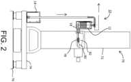
- FIG. 2 shows an example placement of the cooling apparatus according to the embodiment of the present disclosure.
- a transmission electron microscope 70 has a lens barrel 72 which extends in a vertical direction (up-and-down direction).
- an electron gun In the lens barrel 72, an electron gun, a condensing lens, an objective lens, a sample chamber, and the like are provided.
- a sample 78 which is an observation target is held by a sample holder 80.
- a gas molecule trap 82 is provided near the sample 78. The gas molecule trap 82 is provided for trapping contaminant substances, to prevent contamination of the sample, and for increasing the degree of vacuum in the sample chamber.
- a cooling target of the cooling apparatus 10 is the gas molecule trap 82.
- the tank 12 is connected to the gas molecule trap via the heat conducting member 18.
- the gas molecule trap 82 is fixed in the sample chamber via a member having low thermal conductivity (for example, glass).
- the transmission electron microscope 70 has a base (horizontal plate) 74 supported by a pedestal 76.
- the external container 14 is placed on the base 74.
- the supply pipe provided between the external container 14 and the tank 12 has a portion which is elongated along the vertical direction. In FIG. 2 , illustration of the pressure control equipment is omitted.
- FIG. 3 shows an action of the cavity.
- the process of growth of the bubble is shown in steps, by (A) to (G).
- a very small recess (cavity) 102 is present on a tank inner surface 100.
- a small bubble 104 is generated in the cavity.
- the bubble gradually grows (refer to reference numerals 106, 108, 110, and 112).
- a bubble 114 after the growth detaches from the cavity, and moves upward.
- a small bubble 116 remains in the cavity.
- the bubble 116 becomes an origin of a next large bubble. Once a bubble is generated in the cavity, the bubble generation is repeated.
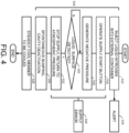
- FIG. 4 shows an example operation of the cooling apparatus according to the embodiment of the present disclosure, as a flowchart.
- FIG. 5 shows a change of temperature of the liquid coolant and a change of the pressure in the tank during a cooling preparation process. First, the example operation will be described, and then, the change of the temperature and the change of the pressure will be described in detail.
- the tank In an initial state, the tank is empty, or the liquid coolant is present in the tank in an uncertain amount.
- the pressure in the tank at the initial state is the atmospheric pressure.
- S10 shows a cooling preparation process
- S28 shows a cooling process.
- a worker injects liquid nitrogen of a predefined amount into the external container.
- an alert sound, light, image, or the like
- S16 the worker operates a supply start button in the operation panel.
- the control unit opens the open/close valve.
- the pressure in the tank changes from the initial pressure (atmospheric pressure) to a first pressure (negative pressure).
- the first pressure can be adjusted by changing an amount of operation of the flow rate adjustment valve.
- liquid nitrogen When the pressure in the tank changes from the atmospheric pressure to the first pressure, the liquid coolant in the external container starts to move to the tank.
- liquid nitrogen first vigorously vaporizes in the supply pipe, and, then, even if liquid nitrogen enters the tank, liquid nitrogen entering the tank vigorously vaporizes.
- nitrogen gas caused by the vaporization pushes the atmospheric air out, and the atmospheric air in the tank is replaced with the nitrogen gas. With this process, the water vapor contained in the atmospheric air is released to the outside. If the pressure in the tank exceeds a predefined pressure due to the vaporization of liquid nitrogen, the relief valve operates automatically. After the supply pipe and the tank are cooled to a certain degree, liquid nitrogen starts to accumulate in the tank.
- the control unit stops the supply of liquid nitrogen at a timing after a predetermined time has elapsed from the detection of the liquid surface height reaching the second height. Specifically, the control unit closes the open/close valve. With this process, the pressure in the tank changes from the first pressure to the second pressure (atmospheric pressure).
- the spontaneous bumping occurs a plurality of times in the liquid coolant in the tank.
- a mechanism of occurrence of the spontaneous bumping will be described later in detail. Due to the spontaneous bumping, typically a relatively large spontaneous bumping which occurs at a last stage, the pressure in the tank is rapidly, temporarily increased, and bubbles included in the liquid coolant liquefy. In experiments, it was confirmed that bubbles liquefy with a pressure increase of greater than or equal to 0.005 MPa (0.05 atmospheres). With this process, the cavity present on the inner surface of the tank is deactivated. Repeated generation of the bubbles due to the cavity stops, or is lessened.
- the member to be cooled is steadily cooled by the cooling apparatus.
- a detector which detects overflow is provided.
- a supply error is judged, and the supply of the liquid coolant may be stopped.
- the supply error may be judged in S24 and the supply of the liquid coolant may be stopped also in the case where the liquid surface is not detected at the second height even after a predetermined time has elapsed from the start of supply of liquid nitrogen.
- the spontaneous bumping may be caused through the above-described control.
- FIG. 5 shows at an upper part a change of the temperature during the cooling preparation process.
- the horizontal axis is a time axis
- the vertical axis is a temperature axis.
- Reference numeral 84 shows a temperature detected by a temperature sensor provided at a first height (lower-side temperature sensor), and reference numeral 86 shows a temperature detected by a temperature sensor provided at a second height (upper-side temperature sensor).
- a parameter Ta shows a boiling point of the liquid coolant under the atmospheric pressure.
- FIG. 5 shows at a lower part a change of the pressure in the tank during the cooling preparation process.
- the horizontal axis is the time axis, and the vertical axis is a pressure axis.
- D1 shows an injection period (first period), and D2 shows a subsequent period following the injection period D1 (second period).
- a parameter pa shows the atmospheric pressure.
- the open/close valve is opened at time t0.
- the pressure in the tank changes from the initial pressure (atmospheric pressure) to the first pressure (negative pressure).
- supply of the liquid coolant into the tank is started. That is, in a state in which the liquid coolant in the external container experiences the atmospheric pressure, when the pressure in the tank becomes the first pressure lower than the atmospheric pressure, due to a pressure difference, the liquid coolant in the external container starts to move into the tank via the supply pipe.
- the pressure in the tank is maintained at the first pressure.
- a gas suctioning force, a weight of liquid nitrogen in the supply pipe 20, and the flow path resistance of the supply pipe 20 contribute to the formation and the maintenance of the first pressure.
- a period t4 the inflow of the heat from the outside is continued, but, because the temperature of the liquid coolant in the tank is lower than the boiling point of the liquid coolant under the atmospheric pressure, the liquid coolant basically does not boil, and settles. However, the temperature of liquid nitrogen gradually increases due to the heat flowing in from the outside, and approaches the boiling point of liquid nitrogen under the atmospheric pressure. At time t5, the temperature detected by the upper-side temperature sensor has reached the boiling point of liquid nitrogen under the atmospheric pressure.
- the temperature of liquid nitrogen reaches the boiling point on the inner surface of the tank at an upper part thereof.
- liquid nitrogen does not immediately boil, and a part of liquid nitrogen is placed in the overheated state.
- spontaneous bumping 92 occurs a plurality of times from a period t6 to a period t8.
- the temperature detected by the lower-side temperature sensor has reached the boiling point of liquid nitrogen under the atmospheric pressure.
- spontaneous bumping 94 for a last time is caused.
- the spontaneous bumping 94 occurs after the temperature detected by the lower-side temperature sensor has reached the boiling point of liquid nitrogen under the atmospheric pressure.
- the last spontaneous bumping 94 is a relatively large bumping. After the occurrence of the last spontaneous bumping 94, no spontaneous bumping occurs.
- Each individual spontaneous bumping, in particular, the last, large spontaneous bumping 94 results in a large pressure increase in a short period of time in the tank. Due to each individual spontaneous bumping, in particular, the last, large spontaneous bumping 94, the bubbles in the cavities on the inner surface of the tank liquefy. That is, the cavities are deactivated.
- a parameter pb in FIG. 5 shows a pressure threshold.
- the cavities are effectively deactivated when a pressure increase exceeding pb is caused.
- the value of pb is 0.005 MPa (0.05 atmospheres), but the value may change according to various conditions.
- the value of pb may be set to 0.003 MPa (0.03 atmospheres), or to 0.007 MPa (0.07 atmospheres).
- thermal equilibrium is reached between the tank and the member to be cooled, before the last spontaneous bumping 94 occurs.
- various conditions should be determined such that the last spontaneous bumping 94 occurs later than the elapsed time of 45 minutes.
- the flow rate may be adjusted by the flow rate adjustment valve so that such conditions are satisfied.
- the flow rate is increased; that is, when a release velocity is increased, the flow path resistance of the supply pipe is increased, and, as a consequence, the first pressure is further lowered, and the temperature of liquid nitrogen in the tank is further reduced.
- the time for the temperature of liquid nitrogen to reach the boiling point of liquid nitrogen under the atmospheric pressure after the supply of liquid nitrogen is stopped can be delayed.
- the temperature of liquid nitrogen is reduced excessively, there is a possibility that liquid nitrogen freezes when the pressure in the tank is returned to the atmospheric pressure. Desirably, the temperature of liquid nitrogen is adjusted so as to avoid such a problem.
- FIG. 6 shows a comparative example.
- a cooling apparatus of the comparative example is connected to a transmission electron microscope.
- the cooling apparatus has a tank 120.
- a funnel 124 is used.
- the funnel 124 and a connection portion 122 of the tank 120 are connected with each other via a bent pipe. In this state, liquid nitrogen is injected into the funnel 124.
- the cooling apparatus of the comparative example is used, the injection operation of liquid nitrogen must be performed at a high location, and the burden of the operation is high.
- the cooling apparatus and cooling preparation method according to the embodiment of the present disclosure, the injection operation at the high location is not necessary, and, thus, the degree of safety of the worker can be improved, and the burden of the operation can be reduced.
- the deactivation of the cavities due to spontaneous bumping may be caused regardless of the placement position of the external container.
- the cooling apparatus is connected to the member to be cooled in the transmission electron microscope, but alternatively, the cooling apparatus may be connected to a member to be cooled in another apparatus.
- the spontaneous bumping may be caused in the liquid coolant by reducing the pressure in the tank during or after the injection of liquid nitrogen, and then increasing the pressure in the tank.
Landscapes
- Engineering & Computer Science (AREA)
- Chemical & Material Sciences (AREA)
- Physics & Mathematics (AREA)
- Mechanical Engineering (AREA)
- Thermal Sciences (AREA)
- General Engineering & Computer Science (AREA)
- Combustion & Propulsion (AREA)
- Analytical Chemistry (AREA)
- Fluid Mechanics (AREA)
- General Physics & Mathematics (AREA)
- Separation By Low-Temperature Treatments (AREA)
Abstract
Description
- The present disclosure relates to a cooling apparatus and a cooling preparation method, and in particular to a cooling apparatus having a tank which stores a liquid coolant.
- A cooling apparatus is an apparatus for cooling a member to be cooled. The cooling apparatuses are used in various fields. For example, in observation of a sample using a transmission electron microscope, the cooling apparatus is used to maintain the sample at a very low temperature, or to maintain a gas molecule trap at a very low temperature. The gas molecule trap is used for preventing contamination of the sample or improve the degree of vacuum. In general, the cooling apparatus has a tank which stores a liquid coolant such as liquid nitrogen (for example, refer to
JP H5-45012 Y - When the liquid coolant in the tank absorbs heat from outside, the liquid coolant boils. More specifically, the heat from the outside is conducted to the liquid coolant via an inner surface of the tank. On the inner surface of the tank, minute scratches, recesses, or the like are present in a non-ignorable number. It is known that bubbles tend to be generated easily and repeatedly at such scratches and recesses. These scratches and recesses are called "cavities".
- More specifically, due to the heat from the outside, the liquid coolant is vaporized in the cavity, and minute bubbles are generated. When a bubble grows into a large bubble, the bubble detaches from the cavity, and moves (floats) upward. After the large bubble detaches from the cavity, a minute bubble remains in the cavity. The minute bubble then grows into a large bubble. Once a bubble is generated in the cavity, bubbles tend to be generated repeatedly.
- The repeated generation of the bubbles in the tank causes the tank to vibrate. In particular, repeated generation of the bubbles at a lower part of the tank causes significant vibration of the tank. The vibration of the tank adversely affects apparatuses to which the tank is connected. For example, when the tank is connected to a transmission electron microscope, the vibration is transmitted from the tank to the transmission electron microscope, and becomes a significant obstacle for sample observation.
- An advantage of the present disclosure lies in reduction of vibration of a tank which stores a liquid coolant. Alternatively, an advantage of the present disclosure lies in deactivating a cavity on an inner surface of the tank which stores a liquid coolant.
- According to one aspect of the present disclosure, there is provided a cooling apparatus comprising: a tank connected to a member to be cooled via a heat conducting member; and pressure control equipment that includes a pump which suctions gas in the tank, and that sets a pressure in the tank to a first pressure during a first period in which a liquid coolant is injected into the tank, and sets the pressure in the tank to a second pressure higher than the first pressure during a second period subsequent to the first period, so that spontaneous bumping is caused in the liquid coolant in the tank during the second period.
- According to another aspect of the present disclosure, there is provided a cooling method comprising: a first step of reducing a pressure in a tank connected to a member to be cooled via a heat conducting member, from an initial pressure to a first pressure, to thereby lower a boiling point of a liquid coolant injected into the tank; a second step of increasing, after the first step, the pressure in the tank from the first pressure to a second pressure, to thereby increase the boiling point of the liquid coolant in the tank; and a third step in which, after the second step, spontaneous bumping is caused in the liquid coolant in the tank with an increase of a temperature of the liquid coolant in the tank, so that bubbles in the liquid coolant in the tank liquefy.
- Embodiment(s) of the present disclosure will be described based on the following figures, wherein:
-
FIG. 1 is a diagram showing an example structure of a cooling apparatus according to an embodiment of the present disclosure; -
FIG. 2 is a diagram showing an example placement of the cooling apparatus according to the embodiment of the present disclosure; -
FIG. 3 is a diagram showing generation of bubbles generated in a cavity; -
FIG. 4 is a diagram showing an example operation of the cooling apparatus according to the embodiment of the present disclosure; -
FIG. 5 is a diagram showing a change of temperature and a change of pressure during a cooling preparation process; and -
FIG. 6 is a diagram showing a cooling apparatus of the related art. - An embodiment of the present disclosure will now be described with reference to the drawings.
- A cooling apparatus according to an embodiment of the present disclosure comprises a tank and pressure control equipment. The tank is connected to a member to be cooled via a heat conducting member. The pressure control equipment has a pump which suctions gas in the tank. The pressure control equipment sets a pressure in the tank to a first pressure during a first period in which a liquid coolant is injected into the tank. The pressure control equipment further sets the pressure in the tank to a second pressure higher than the first pressure during a second period subsequent to the first period, so that spontaneous bumping is caused in the liquid coolant in the tank during the second period.
- According to the above-described structure, desirably, a boiling point of the liquid coolant in the tank is reduced during the first period. That is, the temperature of the liquid coolant in a boiled state is reduced. In the subsequent second period, the pressure in the tank is increased, so that the boiling point of the liquid coolant in the tank is increased. That is, boiling of the liquid coolant is temporarily suppressed. After such a temporary settling process, with an increase in the temperature of the liquid coolant due to heat flowing in from the outside, the temperature of the liquid coolant again reaches the boiling point in the tank. However, because the inflow of the heat is relatively gradual, the boiling of the liquid coolant does not occur immediately, and a part of the liquid coolant is placed in an overheated state. Then, with a small vibration or the like as a trigger, the part of the liquid coolant in the overheated state vaporizes at once; that is, vigorous boiling (bumping) is caused. This phenomenon is the spontaneous bumping described above.
- The spontaneous bumping significantly increases the pressure in the tank for a short period of time. A rapid increase of the pressure causes the bubbles in the liquid coolant to liquefy. That is, the bubbles in the cavity disappear, and repeated generation of the bubbles in the cavity is stopped. That is, the cavity is deactivated.
- After the spontaneous bumping occurs, if a large amount of heat flows into the liquid coolant, the cavity is again activated. Thus, desirably, a thermal equilibrium is formed between the tank and the member to be cooled before the last spontaneous bumping. Even if the heat flows into the liquid coolant from the outside after the thermal equilibrium is reached, if the amount of heat is small or if the heat flows into an upper part of the liquid coolant in the tank, normally, the vibration due to the boiling of the liquid coolant is small, and the problem due to the vibration basically does not occur. The first pressure and the second pressure described above are pressures which are set by the pressure control equipment, and correspond to baselines. Due to the boiling of the liquid coolant (including bumping), a pressure peak is superposed on the baseline.
- In an embodiment, the first pressure is a pressure lower than an atmospheric pressure. The second pressure is the atmospheric pressure. In this structure, first, the pressure in the tank is set to a negative pressure, and the pressure in the tank is then returned to the atmospheric pressure. With the use of the atmospheric pressure, the structure of the pressure control equipment can be simplified, and the control of the pressure can be facilitated. In the embodiment, the pressure in the tank is changed from the initial pressure (atmospheric pressure) to the first pressure at the start of the first period.
- In order to cause the spontaneous bumping in the liquid coolant presuming the inflow of the heat from the outside, a manipulation to increase the boiling point of the liquid coolant from a first temperature to a second temperature is important. Thus, the first temperature may be set at an arbitrary temperature, and the second temperature may be set with reference to the first temperature.
- The cooling apparatus according to an embodiment further comprises a sensor that detects a liquid surface height of the liquid coolant in the tank. Based on an output signal of the sensor, the pressure control equipment determines a timing of changing the pressure in the tank to the second pressure. A part of the liquid coolant injected into the tank is vaporized by the boiling. It is difficult to identify a liquid surface level (amount of liquid) of the liquid coolant in the tank based on an amount of supply of the liquid coolant. According to the above-described structure, it becomes possible to control the pressure in the tank based on an actual liquid surface height of the liquid coolant.
- The cooling apparatus according to the embodiment further comprises an external container into which the liquid coolant is injected, and a supply pipe through which the liquid coolant in the external container is sent to the tank. The first pressure is a pressure lower than an atmospheric pressure. The liquid coolant in the external container is introduced into the tank via the supply pipe during the first period. According to this structure, the liquid coolant is naturally introduced into the tank through the negative pressure in the tank. Therefore, the injection operation of the liquid coolant can be facilitated. The negative pressure is a pressure lower than the atmospheric pressure.
- In an embodiment, the external container is placed at a position lower than the tank.
- According to this structure, a filling operation of the liquid coolant to the external container can be facilitated. By avoiding an operation at a high location, safety of a worker can be improved.
- In an embodiment, a porous member is provided at an intake port of the supply pipe. According to this structure, several advantages can be obtained. First, the porous member can function as a filter. That is, intrusion of foreign objects such as ice into the tank can be prevented. Secondly, if gas generated in the tank flows out from the porous member in a state in which the porous member is exposed, the surface of the porous member is covered by the gas. With this configuration, intrusion of air into the supply pipe can be blocked. Thirdly, because a flow path resistance is increased by the porous member, a large pressure increase can be caused in the tank at the time of occurrence of the spontaneous bumping without providing an open/close valve midway on the supply pipe and closing the valve.
- In an embodiment, the pressure control equipment includes a suctioning pipe provided between the pump and the tank, and a detector which detects a temperature at a detection position on the suctioning pipe. Overflow of the liquid coolant from the tank is judged based on the temperature detected by the detector. According to this structure, the overflow of the liquid coolant can be judged with a simple structure. In an embodiment to be described below, a control unit functions as an overflow judgment device.
- In an embodiment, the pressure control equipment includes a relief valve which operates when the pressure in the tank reaches a predetermined pressure. The relief valve operates when the pressure in the tank becomes higher than a predetermined value (upper limit value), exceeding a pressure which allows deactivation of the cavity. According to this structure, the degree of safety can be improved.
- A cooling preparation method according to an embodiment of the present disclosure comprises a first step, a second step, and a third step. In the first step, a pressure in a tank connected to a member to be cooled via a heat conducting member is reduced from an initial pressure to a first pressure. With this process, a boiling point of a liquid coolant injected into the tank is lowered. In the second step, after the first step, the pressure in the tank is increased from the first pressure to the second pressure. With this process, the boiling point of the liquid coolant in the tank is increased, and boiling of the liquid coolant in the tank is temporarily suppressed. In the third step, after the second step, spontaneous bumping is caused in the liquid coolant in the tank with an increase of a temperature of the liquid coolant in the tank. With this process, bubbles in the liquid coolant in the tank liquefy. That is, the cavity on the inner surface of the tank is deactivated. By suppressing the repeated generation of the bubbles in the liquid coolant in the tank, it is possible to reduce the vibration caused in the tank in a cooling state of the member to be cooled.
-
FIG. 1 schematically shows an example structure of a cooling apparatus according to an embodiment of the present disclosure. A cooling apparatus according to the embodiment of the present disclosure is, for example, an apparatus for cooling a member to be cooled included in an electron microscope. Alternatively, the cooling apparatus according to the embodiment may be used for other usages. In an embodiment of the present disclosure, a liquid coolant is specifically liquid nitrogen. Alternatively, other liquid coolants may be used. - In
FIG. 1 , thecooling apparatus 10 comprises atank 12, anexternal container 14,pressure control equipment 16, asupply pipe 20, and asuctioning pipe 22. Thetank 12 is a tank which stores liquid nitrogen. A side wall of thetank 12 is formed from, for example, stainless steel, and a bottom wall of thetank 12 is formed from, for example, copper. Thetank 12 has a vacuum heat-insulation structure 50. - A
bottom surface 12A of thetank 12 is connected to aheat conducting member 18. Theheat conducting member 18 is connected to a member to be cooled (not shown). Theheat conducting member 18 is formed from, for example, a copper plate, a copper mesh wire, or the like. The member to be cooled is a sample, a gas molecule trap, or the like. - A
temperature sensor 44 is provided on an outer surface of thetank 12 at a lower part thereof. Atemperature sensor 46 is provided on the outer surface of thetank 12 at an upper part thereof. With reference to an inner bottom surface height of thetank 12, thetemperature sensor 44 is placed at a first height, and thetemperature sensor 46 is placed at a second height. The second height is a reference height for determining a timing to judge stopping of supply of liquid nitrogen. Thetemperature sensor 44 is provided in order to detect presence or absence of liquid nitrogen in thetank 12. Acontrol unit 34 to be described below judges that a liquid surface of liquid nitrogen has reached or exceeded the second height based on an output signal of thetemperature sensor 46. - The
external container 14 is a dewar which stores liquid nitrogen. Theexternal container 14 has a vacuum heat-insulation structure or a heat-insulation member 60. Theexternal container 14 has anopening 14A, through which liquid nitrogen is injected into the external container 14 (refer to reference numeral 52). Atemperature sensor 56 is provided on an inner surface of theexternal container 14 at a lower part thereof, and atemperature sensor 58 is provided on the inner surface of theexternal container 14 at an upper part thereof. Specifically, with reference to the inner bottom surface height of theexternal container 14, thetemperature sensor 56 is provided at a third height, and thetemperature sensor 58 is provided at a fourth height. Alternatively, thetemperature sensors external container 14. - The
temperature sensor 56 is provided in order to judge that liquid nitrogen is present in theexternal container 14 in an amount greater than or equal to a certain amount. More specifically, thetemperature sensor 56 is for confirming that the liquid surface of liquid nitrogen is at a position higher than an upper surface of aporous member 54 to be described later. Thetemperature sensor 58 is provided for preventing overflow of liquid nitrogen from theexternal container 14. - A heat-insulation member is provided at an outer side of the
supply pipe 20, but illustration thereof is omitted. Thesupply pipe 20 has afirst portion 20A which extends along a vertical direction, asecond portion 20B which extends along a horizontal direction, and athird portion 20C which extends along the vertical direction. - A lower end opening (intake port) of the
first portion 20A is covered with theporous member 54. Theporous member 54 has a large number of minute pores, each of which permits passage of liquid and gas. Theporous member 54 is formed from, for example, a sintered metal. Alternatively, theporous member 54 may be formed from a ceramic or the like. - The
porous member 54 functions as a filter. That is, passage of a foreign object such as ice is blocked by theporous member 54. In addition, theporous member 54, together with a small inner size of thesupply pipe 20, contributes to an increase of a flow path resistance. After liquid nitrogen is injected into thetank 12, nitrogen gas from the tank flows from a surface of theporous member 54 to the outside. When the amount of liquid nitrogen in theexternal container 14 becomes low, theporous member 54 is exposed. However, because theporous member 54 is enclosed by the nitrogen gas, intrusion of air into thesupply pipe 20 is blocked. At the same time, dew formation and frost formation on the surface of theporous member 54 are prevented. - As illustrated, the
external container 14 is placed at a position lower than thetank 12. More specifically, a bottom wall of theexternal container 14 is placed at a position lower than a bottom wall of thetank 12. Although it is possible to inject liquid nitrogen into thetank 12 from a position higher than thetank 12, in such a configuration, an operation at a high location by a worker is necessary. According to the structure of the embodiment, because the worker only needs to perform the operation at a low location, burden of the worker can be reduced, and the safety of the worker can be improved. - A
lower end 40 of thethird portion 20C of thesupply pipe 20 extends into thetank 12. Thelower end 40 functions as an ejection nozzle. - The
suctioning pipe 22 has afirst portion 22A which extends along the vertical direction, asecond portion 22B which extends along the horizontal direction, and aU-shaped portion 24C which belongs to adetector 24. A heat-insulation member is provided as necessary also on an outer side of thesuctioning pipe 22. TheU-shaped portion 24C is formed from a portion which extends downward, a portion which is curved, and a portion which extends upward. At downstream of theU-shaped portion 24C, a plurality of devices are placed, details of which are to be described below. Alower end 42 of thefirst portion 22A extends into thetank 12, and functions as a suctioning nozzle. - The
detector 24 detects overflow of liquid nitrogen from thetank 12. Thedetector 24 has atemperature sensor 62 provided on an outer surface of a bottom portion (bottom surface) of theU-shaped portion 24C. When liquid nitrogen enters theU-shaped portion 24C, a temperature detected by thetemperature sensor 62 is rapidly reduced. Based on this, thecontrol unit 34 to be described later judges the occurrence of overflow. TheU-shaped portion 24C is formed from a material with superior thermal conductivity (for example, copper). - Next, the
pressure control equipment 16 will be described. Thepressure control equipment 16 has arelief valve 26, a flowrate adjustment valve 28, an open/close valve (electromagnetic valve) 30, and avacuum pump 32, and additionally has thecontrol unit 34 which controls operations of these components. - The
relief valve 26 is a safety valve. Therelief valve 26 is normally in a closed state, and is automatically opened when a pressure in thesuctioning pipe 22; that is, the pressure in thetank 12, has reached a predetermined pressure (upper limit value). The predetermined pressure is, for example, 0.03 MPa (0.3 atmospheres). Alternatively, therelief valve 26 may be provided at another position, so long as the function thereof is realized. The flowrate adjustment valve 28 is a valve for adjusting a flow rate of gas flowing in thesuctioning pipe 22, and, in the embodiment, the flowrate adjustment valve 28 functions during a suctioning process. - The
vacuum pump 32 is a suctioning apparatus for suctioning gas in thetank 12, and reducing the pressure in thetank 12 to a pressure lower than the atmospheric pressure. The vacuum pump may be operated only during the suctioning, or thevacuum pump 32 may be operated at all times. Alternatively, a buffer tank may be provided upstream of thevacuum pump 32. Various pumps may be used as thevacuum pump 32. Alternatively, a pump for vacuuming a lens barrel of a transmission electron microscope may be used as thevacuum pump 32. - The
control unit 34 is formed from a computer, a microcomputer, or the like. More specifically, thecontrol unit 34 is formed from a processor which executes a program. Thecontrol unit 34 controls operations of the open/close valve 30 and operations of thevacuum pump 32. Alternatively, thecontrol unit 34 may further control operations of the flowrate adjustment valve 28. Output signals from thetemperature sensors control unit 34. Thecontrol unit 34 controls operations of thecooling apparatus 10 based on these output signals. - More specifically, the
control unit 34 judges that liquid nitrogen is present in thetank 12 based on the output signal of thetemperature sensor 44. In addition, thecontrol unit 34 judges that the liquid surface of liquid nitrogen has reached the second height based on the output signal of thetemperature sensor 46. As will be described later, thecontrol unit 34 changes the pressure in the tank from the first pressure (negative pressure) to the second pressure (atmospheric pressure) at a timing when a predetermined time has elapsed from a timing of judgment of reaching of the liquid surface. Thecontrol unit 34 judges overflow of liquid nitrogen based on the output signal of thetemperature sensor 62. When liquid nitrogen has overflown, an alert is output. - The
control unit 34 judges that liquid nitrogen is present in theexternal container 14 in an amount greater than or equal to a certain amount, based on the output signal of thetemperature sensor 56. Thecontrol unit 34 performs the supply of liquid nitrogen from theexternal container 14 to thetank 12 only when liquid nitrogen is present in theexternal container 14 in the certain amount. Thecontrol unit 34 judges that the liquid surface of liquid nitrogen has reached the fourth height (upper limit of liquid surface height) based on the output signal of thetemperature sensor 58. In this case, an alert is output. - An
operation panel 36 which is an inputting device is connected to thecontrol unit 34, and adisplay 38 is connected to thecontrol unit 34. Theoperation panel 36 includes a plurality of switches, a plurality of buttons, or the like. Thedisplay 38 is formed from, for example, a liquid crystal display. - The
supply pipe 20 is relatively long, and the inner size of thesupply pipe 20 is relatively small. Further, theporous member 54 is provided on the intake port of thesupply pipe 20. Therefore, the flow path resistance of thesupply pipe 20 is large. The open/close valve 30 is provided on thesuctioning pipe 22. When the open/close valve 30 is in the closed state, the inside of thetank 12 is close to a closed space. In this state, a rapid pressure increase in a short period of time is caused in thetank 12, due to spontaneous bumping to be described below. From another perspective, a length and an inner size of thesupply pipe 20, a porosity of theporous member 54, and the like, are determined in such a manner that the pressure increase as described above occurs. - When moisture enters the
tank 12 and ice is generated in the tank, a relatively large bubble tends to be more easily generated due to the ice. In consideration of this, a heater (not shown) is provided at an outer side of thetank 12 at the bottom thereof. Prior to the supply of the liquid coolant, electricity is applied to the heater as necessary, so that the moisture in thetank 12 is released to the outside as water vapor. A heater (not shown) is also provided at an outer side of theexternal container 14 at an upper part thereof. When frost or ice is attached to the upper part of theexternal container 14, the frost or ice attached to the upper part of theexternal container 14 can be removed by applying electricity to the heater. -
FIG. 2 shows an example placement of the cooling apparatus according to the embodiment of the present disclosure. Atransmission electron microscope 70 has alens barrel 72 which extends in a vertical direction (up-and-down direction). In thelens barrel 72, an electron gun, a condensing lens, an objective lens, a sample chamber, and the like are provided. Asample 78 which is an observation target is held by asample holder 80. Agas molecule trap 82 is provided near thesample 78. Thegas molecule trap 82 is provided for trapping contaminant substances, to prevent contamination of the sample, and for increasing the degree of vacuum in the sample chamber. - A cooling target of the
cooling apparatus 10 is thegas molecule trap 82. Thetank 12 is connected to the gas molecule trap via theheat conducting member 18. Thegas molecule trap 82 is fixed in the sample chamber via a member having low thermal conductivity (for example, glass). - The
transmission electron microscope 70 has a base (horizontal plate) 74 supported by apedestal 76. Theexternal container 14 is placed on thebase 74. The supply pipe provided between theexternal container 14 and thetank 12 has a portion which is elongated along the vertical direction. InFIG. 2 , illustration of the pressure control equipment is omitted. -
FIG. 3 shows an action of the cavity. The process of growth of the bubble is shown in steps, by (A) to (G). A very small recess (cavity) 102 is present on a tankinner surface 100. Asmall bubble 104 is generated in the cavity. The bubble gradually grows (refer to referencenumerals bubble 114 after the growth detaches from the cavity, and moves upward. In this process, asmall bubble 116 remains in the cavity. Thebubble 116 becomes an origin of a next large bubble. Once a bubble is generated in the cavity, the bubble generation is repeated. -
FIG. 4 shows an example operation of the cooling apparatus according to the embodiment of the present disclosure, as a flowchart.FIG. 5 shows a change of temperature of the liquid coolant and a change of the pressure in the tank during a cooling preparation process. First, the example operation will be described, and then, the change of the temperature and the change of the pressure will be described in detail. - In an initial state, the tank is empty, or the liquid coolant is present in the tank in an uncertain amount. The pressure in the tank at the initial state (initial pressure) is the atmospheric pressure. In the following, for the convenience of the description, a situation is presumed in which the tank is empty in the initial state.
- In
FIG. 4 , S10 shows a cooling preparation process, and S28 shows a cooling process. First, in S12, a worker injects liquid nitrogen of a predefined amount into the external container. When the liquid surface height of liquid nitrogen exceeds the upper limit height (or when a predetermined time has elapsed from the time when the liquid surface height exceeds the upper limit), in S14, an alert (sound, light, image, or the like) is output. After liquid nitrogen in the predefined amount is injected into the external container, in S16, the worker operates a supply start button in the operation panel. - When the supply start button is operated in a state in which the vacuum pump is operating, the control unit opens the open/close valve. With this process, the pressure in the tank changes from the initial pressure (atmospheric pressure) to a first pressure (negative pressure). The first pressure can be adjusted by changing an amount of operation of the flow rate adjustment valve. When the liquid surface height of liquid nitrogen in the external container is lower than a first liquid surface height (lower limit), the supply of liquid nitrogen is not started. If a similar situation occurs in the middle of supply of liquid nitrogen, the supply of liquid nitrogen is stopped.
- When the pressure in the tank changes from the atmospheric pressure to the first pressure, the liquid coolant in the external container starts to move to the tank. In a state in which the supply pipe or the tank is not sufficiently cooled, liquid nitrogen first vigorously vaporizes in the supply pipe, and, then, even if liquid nitrogen enters the tank, liquid nitrogen entering the tank vigorously vaporizes. When atmospheric air is contained in the tank, nitrogen gas caused by the vaporization pushes the atmospheric air out, and the atmospheric air in the tank is replaced with the nitrogen gas. With this process, the water vapor contained in the atmospheric air is released to the outside. If the pressure in the tank exceeds a predefined pressure due to the vaporization of liquid nitrogen, the relief valve operates automatically. After the supply pipe and the tank are cooled to a certain degree, liquid nitrogen starts to accumulate in the tank.
- In S20, it is detected that the liquid surface of liquid nitrogen in the tank has reached the second height (predefined height). In S22, the control unit stops the supply of liquid nitrogen at a timing after a predetermined time has elapsed from the detection of the liquid surface height reaching the second height. Specifically, the control unit closes the open/close valve. With this process, the pressure in the tank changes from the first pressure to the second pressure (atmospheric pressure).
- Then, after a certain settling period, in S26, normally, the spontaneous bumping occurs a plurality of times in the liquid coolant in the tank. A mechanism of occurrence of the spontaneous bumping will be described later in detail. Due to the spontaneous bumping, typically a relatively large spontaneous bumping which occurs at a last stage, the pressure in the tank is rapidly, temporarily increased, and bubbles included in the liquid coolant liquefy. In experiments, it was confirmed that bubbles liquefy with a pressure increase of greater than or equal to 0.005 MPa (0.05 atmospheres). With this process, the cavity present on the inner surface of the tank is deactivated. Repeated generation of the bubbles due to the cavity stops, or is lessened.
- In S28, the member to be cooled is steadily cooled by the cooling apparatus. In preparation for a case in which there is a defect in the temperature sensor placed at the second height, and the detection of the liquid surface at the second height fails, a detector which detects overflow is provided. When an elapsed time from a point in time at which the output signal from the temperature sensor placed at the second height becomes lower than a threshold exceeds a predetermined time, in S24, a supply error is judged, and the supply of the liquid coolant may be stopped. In addition, the supply error may be judged in S24 and the supply of the liquid coolant may be stopped also in the case where the liquid surface is not detected at the second height even after a predetermined time has elapsed from the start of supply of liquid nitrogen.
- In the case in which an uncertain amount of liquid coolant remains in the tank in the initial state also, the spontaneous bumping may be caused through the above-described control.
-
FIG. 5 shows at an upper part a change of the temperature during the cooling preparation process. The horizontal axis is a time axis, and the vertical axis is a temperature axis.Reference numeral 84 shows a temperature detected by a temperature sensor provided at a first height (lower-side temperature sensor), andreference numeral 86 shows a temperature detected by a temperature sensor provided at a second height (upper-side temperature sensor). A parameter Ta shows a boiling point of the liquid coolant under the atmospheric pressure. -
FIG. 5 shows at a lower part a change of the pressure in the tank during the cooling preparation process. The horizontal axis is the time axis, and the vertical axis is a pressure axis. D1 shows an injection period (first period), and D2 shows a subsequent period following the injection period D1 (second period). A parameter pa shows the atmospheric pressure. - In a state in which the vacuum pump is operating, the open/close valve is opened at time t0. With this process, the pressure in the tank changes from the initial pressure (atmospheric pressure) to the first pressure (negative pressure). As a consequence, supply of the liquid coolant into the tank is started. That is, in a state in which the liquid coolant in the external container experiences the atmospheric pressure, when the pressure in the tank becomes the first pressure lower than the atmospheric pressure, due to a pressure difference, the liquid coolant in the external container starts to move into the tank via the supply pipe. The pressure in the tank is maintained at the first pressure. A gas suctioning force, a weight of liquid nitrogen in the
supply pipe 20, and the flow path resistance of thesupply pipe 20 contribute to the formation and the maintenance of the first pressure. - In a state in which the supply pipe and the tank are not sufficiently cooled, first, the liquid coolant in the pipe vigorously boils, and then, the liquid coolant in the tank boils vigorously. After liquid nitrogen or the nitrogen gas starts to enter the tank from the external container, the temperature detected by the lower-side temperature sensor is rapidly reduced, and, at a slightly later time, the temperature detected by the upper-side temperature sensor is rapidly reduced.
- In a period t1, as described above, vigorous boiling is caused in the tank (refer to reference numeral 88). In the period t1, due to a rapid increase of thermal conductivity in the process of the tank (in particular the bottom wall) and the heat conducting member reaching a very low temperature, the inflow of the heat into the tank rapidly increases. As a result, an
initial bumping 90 is caused. When a thermal capacity of the member to be cooled is relatively large, and the member to be cooled is not sufficiently cooled, the inflow of the heat is large, and film boiling may be caused, exceeding nucleate boiling. When liquid nitrogen is supplied to a tank which is empty at a normal temperature, the initial bumping 90 tends to be easily caused. On the other hand, when some amount of liquid nitrogen remains in the tank and the tank is cooled, such aninitial bumping 90 tends to not occur easily. - If the initial bumping is caused after a large amount of liquid nitrogen is stored in the tank, in particular, after the tank reaches a full state, liquid nitrogen overflows from the tank, resulting in waste of liquid nitrogen. Therefore, the flow rate or the like is adjusted so that the initial bumping is caused before the inside of the tank becomes full.
- After the occurrence of the
initial bumping 90, the amount of heat flowing into liquid nitrogen in the tank is relatively large, and boiling (nucleate boiling) of liquid nitrogen is continued. - At time t2, following the lower-side temperature sensor, the detected temperature of the upper-side temperature sensor also becomes lower than the boiling point Ta of the liquid coolant under the atmospheric pressure. The detected temperatures of the two temperature sensors respectively show actual boiling points of the liquid coolant at the corresponding heights. At the time t2, when the liquid surface of the liquid coolant is detected by the upper-side temperature sensor, the open/close valve is closed at a timing t3 after a predetermined time has elapsed from the detection of the liquid surface, and the pressure in the tank is switched from the first pressure (negative pressure) to the second pressure (atmospheric pressure). With this process, the supply of the liquid coolant into the tank is stopped. The bubbles in the liquid coolant liquefy at the time of the increase in the pressure.
- In general, the detected temperature of the upper-side temperature sensor is higher than the detected temperature of the lower-side temperature sensor. This is because, when the liquid nitrogen in the tank is not stirred so significantly, liquid nitrogen having a lower temperature is heavier than liquid nitrogen having a higher temperature.
- In a period t4, the inflow of the heat from the outside is continued, but, because the temperature of the liquid coolant in the tank is lower than the boiling point of the liquid coolant under the atmospheric pressure, the liquid coolant basically does not boil, and settles. However, the temperature of liquid nitrogen gradually increases due to the heat flowing in from the outside, and approaches the boiling point of liquid nitrogen under the atmospheric pressure. At time t5, the temperature detected by the upper-side temperature sensor has reached the boiling point of liquid nitrogen under the atmospheric pressure.
- Then, at the time t5, the temperature of liquid nitrogen reaches the boiling point on the inner surface of the tank at an upper part thereof. However, because the inflow of the heat is relatively gradual, liquid nitrogen does not immediately boil, and a part of liquid nitrogen is placed in the overheated state. Under such a situation, with a small vibration or the like as a trigger, the part of liquid nitrogen in the overheated state vaporizes at once. Specifically, in the illustrated example configuration, spontaneous bumping 92 occurs a plurality of times from a period t6 to a period t8. At time t7, the temperature detected by the lower-side temperature sensor has reached the boiling point of liquid nitrogen under the atmospheric pressure.
- At time t9, spontaneous bumping 94 for a last time is caused. The
spontaneous bumping 94 occurs after the temperature detected by the lower-side temperature sensor has reached the boiling point of liquid nitrogen under the atmospheric pressure. The last spontaneous bumping 94 is a relatively large bumping. After the occurrence of the lastspontaneous bumping 94, no spontaneous bumping occurs. Each individual spontaneous bumping, in particular, the last, largespontaneous bumping 94, results in a large pressure increase in a short period of time in the tank. Due to each individual spontaneous bumping, in particular, the last, largespontaneous bumping 94, the bubbles in the cavities on the inner surface of the tank liquefy. That is, the cavities are deactivated. A parameter pb inFIG. 5 shows a pressure threshold. The cavities are effectively deactivated when a pressure increase exceeding pb is caused. As described above, the value of pb is 0.005 MPa (0.05 atmospheres), but the value may change according to various conditions. For example, the value of pb may be set to 0.003 MPa (0.03 atmospheres), or to 0.007 MPa (0.07 atmospheres). - In order to deactivate the cavities and to maintain this state with the last, large
spontaneous bumping 94, desirably, thermal equilibrium is reached between the tank and the member to be cooled, before the last spontaneous bumping 94 occurs. For example, if the thermal equilibrium is reached between the tank and the member to be cooled after 45 minutes has elapsed from the start of the supply of liquid nitrogen, various conditions should be determined such that the last spontaneous bumping 94 occurs later than the elapsed time of 45 minutes. The flow rate may be adjusted by the flow rate adjustment valve so that such conditions are satisfied. For example, when the flow rate is increased; that is, when a release velocity is increased, the flow path resistance of the supply pipe is increased, and, as a consequence, the first pressure is further lowered, and the temperature of liquid nitrogen in the tank is further reduced. In this case, the time for the temperature of liquid nitrogen to reach the boiling point of liquid nitrogen under the atmospheric pressure after the supply of liquid nitrogen is stopped can be delayed. However, if the temperature of liquid nitrogen is reduced excessively, there is a possibility that liquid nitrogen freezes when the pressure in the tank is returned to the atmospheric pressure. Desirably, the temperature of liquid nitrogen is adjusted so as to avoid such a problem. - After the period t8, the inflow of the heat into the tank continues, and the boiling of liquid nitrogen in the tank continues. However, after the thermal equilibrium has been reached between the tank and the member to be cooled, the heat flowing into the upper part of the tank becomes dominant. Therefore, liquid nitrogen boils mostly at the upper part in the tank, more specifically, of the inner surface of the tank, at a location near the liquid surface. A vibration caused by the bubble generated near the liquid surface is smaller than a vibration caused by the bubble generated at the lower part of the tank, and a dynamical influence on the tank is smaller. Because heat is taken away by the evaporation of the liquid coolant at the liquid surface, there is a possibility that the boiling stopped state continues for a certain extent.
- In experiments, it has been confirmed that, with reference to the supply start time of liquid nitrogen, the thermal equilibrium was reached after elapse of 45 minutes, and last spontaneous bumping later occurred after elapse of 65 minutes. Then, a low vibration state was caused, and was maintained for a long period of time until liquid nitrogen in the tank was exhausted.
-
FIG. 6 shows a comparative example. A cooling apparatus of the comparative example is connected to a transmission electron microscope. The cooling apparatus has atank 120. When liquid nitrogen is injected into thetank 120, afunnel 124 is used. Thefunnel 124 and aconnection portion 122 of thetank 120 are connected with each other via a bent pipe. In this state, liquid nitrogen is injected into thefunnel 124. When the cooling apparatus of the comparative example is used, the injection operation of liquid nitrogen must be performed at a high location, and the burden of the operation is high. - In the contrary, according to the cooling apparatus and cooling preparation method according to the embodiment of the present disclosure, the injection operation at the high location is not necessary, and, thus, the degree of safety of the worker can be improved, and the burden of the operation can be reduced. However, the deactivation of the cavities due to spontaneous bumping may be caused regardless of the placement position of the external container. In the embodiment of the present disclosure, the cooling apparatus is connected to the member to be cooled in the transmission electron microscope, but alternatively, the cooling apparatus may be connected to a member to be cooled in another apparatus. The spontaneous bumping may be caused in the liquid coolant by reducing the pressure in the tank during or after the injection of liquid nitrogen, and then increasing the pressure in the tank.
Claims (10)
- A cooling apparatus (10) comprising:a tank (12) connected to a member to be cooled via a heat conducting member (18); anda pressure control equipment (16) that includes a pump (32) which suctions gas in the tank (12), and that sets a pressure in the tank (12) to a first pressure during a first period in which a liquid coolant is injected into the tank (12), and sets the pressure in the tank (12) to a second pressure higher than the first pressure during a second period subsequent to the first period, so that spontaneous bumping is caused in the liquid coolant in the tank (12) during the second period.
- The cooling apparatus (10) according to claim 1, wherein
the first pressure is a pressure lower than an atmospheric pressure. - The cooling apparatus (10) according to claim 2, wherein
the second pressure is the atmospheric pressure. - The cooling apparatus (10) according to any preceding claim, further comprising:a sensor (46) that detects a liquid surface height of the liquid coolant in the tank (12), whereinthe pressure control equipment (16) determines a timing of changing the pressure in the tank (12) to the second pressure based on an output signal of the sensor (46).
- The cooling apparatus (10) according to any preceding claim, further comprising:an external container (14) into which the liquid coolant is injected; anda supply pipe (20) through which the liquid coolant in the external container is sent to the tank (12), whereinthe first pressure is a pressure lower than an atmospheric pressure, andthe liquid coolant in the external container (14) is introduced into the tank (12) via the supply pipe (20) during the first period.
- The cooling apparatus (10) according to claim 5, wherein
the external container (14) is placed at a position lower than the tank (12). - The cooling apparatus (10) according to claim 5, wherein
a porous member (54) is provided at an intake port of the supply pipe (20). - The cooling apparatus (10) according to any preceding claim, wherein
the pressure control equipment (16) includes:a suctioning pipe (22) provided between the pump (32) and the tank (12); anda detector (62) which detects a temperature at a detection position on the suctioning pipe (22), andoverflow of the liquid coolant from the tank (12) is judged based on the temperature detected by the detector (62). - The cooling apparatus (10) according to any preceding claim, wherein
the pressure control equipment (16) includes a relief valve which operates when the pressure in the tank (12) has reached a predetermined pressure. - A cooling preparation method, comprising:a first step (S18) of reducing a pressure in a tank (12) connected to a member to be cooled via a heat conducting member (18) from an initial pressure to a first pressure, to thereby lower a boiling point of a liquid coolant injected into the tank (12);a second step (S22) of increasing, after the first step (S18), the pressure in the tank (12) from the first pressure to a second pressure, to thereby increase the boiling point of the liquid coolant in the tank (12); anda third step (S26) in which, after the second step, spontaneous bumping is caused in the liquid coolant in the tank (12) with an increase of a temperature of the liquid coolant in the tank (12), so that bubbles in the liquid coolant in the tank (12) liquefy.
Applications Claiming Priority (1)
| Application Number | Priority Date | Filing Date | Title |
|---|---|---|---|
| JP2023214426A JP2025098351A (en) | 2023-12-20 | 2023-12-20 | Cooler and cooling preparation method |
Publications (2)
| Publication Number | Publication Date |
|---|---|
| EP4576156A2 true EP4576156A2 (en) | 2025-06-25 |
| EP4576156A3 EP4576156A3 (en) | 2025-10-08 |
Family
ID=93520757
Family Applications (1)
| Application Number | Title | Priority Date | Filing Date |
|---|---|---|---|
| EP24212480.8A Pending EP4576156A3 (en) | 2023-12-20 | 2024-11-12 | Cooling apparatus and cooling preparation method |
Country Status (4)
| Country | Link |
|---|---|
| US (1) | US20250207827A1 (en) |
| EP (1) | EP4576156A3 (en) |
| JP (1) | JP2025098351A (en) |
| CN (1) | CN120176347A (en) |
Citations (1)
| Publication number | Priority date | Publication date | Assignee | Title |
|---|---|---|---|---|
| JPH0545012A (en) | 1991-08-09 | 1993-02-23 | Tabai Espec Corp | Compression type freezing method and freezer device |
Family Cites Families (8)
| Publication number | Priority date | Publication date | Assignee | Title |
|---|---|---|---|---|
| JPS625630Y2 (en) * | 1980-10-25 | 1987-02-09 | ||
| JPS58117057U (en) * | 1982-02-04 | 1983-08-10 | 日本電子株式会社 | Coolers for electron microscopes, etc. |
| JPH056498Y2 (en) * | 1986-07-18 | 1993-02-19 | ||
| JP2733243B2 (en) * | 1988-03-31 | 1998-03-30 | 科学技術振興事業団 | Ion source chamber |
| JP2004028516A (en) * | 2002-06-28 | 2004-01-29 | Sanyo Electric Co Ltd | Storage device |
| JP5008252B2 (en) * | 2004-05-18 | 2012-08-22 | パナソニック株式会社 | Liquid fuel container for fuel cell and fuel cell system |
| EP2443644B8 (en) * | 2009-06-18 | 2013-05-15 | Carl Zeiss Microscopy, LLC | Cooled charged particle systems and methods |
| WO2017098574A1 (en) * | 2015-12-08 | 2017-06-15 | 株式会社日立ハイテクノロジーズ | Anti-contamination trap, control method therefor, and charged particle beam device |
-
2023
- 2023-12-20 JP JP2023214426A patent/JP2025098351A/en active Pending
-
2024
- 2024-11-12 EP EP24212480.8A patent/EP4576156A3/en active Pending
- 2024-12-19 CN CN202411882147.8A patent/CN120176347A/en active Pending
- 2024-12-19 US US18/986,888 patent/US20250207827A1/en active Pending
Patent Citations (1)
| Publication number | Priority date | Publication date | Assignee | Title |
|---|---|---|---|---|
| JPH0545012A (en) | 1991-08-09 | 1993-02-23 | Tabai Espec Corp | Compression type freezing method and freezer device |
Also Published As
| Publication number | Publication date |
|---|---|
| EP4576156A3 (en) | 2025-10-08 |
| CN120176347A (en) | 2025-06-20 |
| JP2025098351A (en) | 2025-07-02 |
| US20250207827A1 (en) | 2025-06-26 |
Similar Documents
| Publication | Publication Date | Title |
|---|---|---|
| KR101054683B1 (en) | Cold Trap and Recycling Method | |
| US10393099B2 (en) | Cryopump system, cryopump controller, and cryopump regeneration method | |
| JP2018137419A (en) | Substrate processing apparatus | |
| US20250207827A1 (en) | Cooling Apparatus and Cooling Preparation Method | |
| KR102544881B1 (en) | vacuum chiller | |
| JP2016160884A (en) | Cryopump system, cryopump control device and cryopump regeneration method | |
| JP6794735B2 (en) | Cooling unit and air removal device | |
| KR102182891B1 (en) | Degassing device and degassing method | |
| KR100634654B1 (en) | ESR chamber cooling system and treatment | |
| TW202214959A (en) | Cryopump and regeneration method of cryopump | |
| KR100626988B1 (en) | Gas discharge treatment of ESR refrigerant | |
| JP2017172380A (en) | Cryopump, cryopump occlusion gas quantity estimation device, and cryopump occlusion gas quantity estimation method | |
| JP4429106B2 (en) | Substrate etching equipment | |
| TW202010939A (en) | Cryopump and method for monitoring cryopump | |
| US10481222B2 (en) | Fluid path insert for a cryogenic cooling system | |
| JP5898967B2 (en) | Vacuum cooling device | |
| JP5676976B2 (en) | Capacitor cooling water control device for steam injection vacuum pump | |
| US9186601B2 (en) | Cryopump drain and vent | |
| JP5729678B2 (en) | Cleaning device | |
| JP4436863B2 (en) | Cooling trap unit with regenerative structure | |
| US3940121A (en) | Metal vapor-trapping system | |
| JP2019132435A (en) | Vacuum cooling device | |
| JPH04260439A (en) | Heating and cooling apparatus | |
| US4427444A (en) | Method of refining molten metal with stirring by repeated operation of suction and discharge | |
| KR101118701B1 (en) | Supply device for high purity gas |
Legal Events
| Date | Code | Title | Description |
|---|---|---|---|
| PUAI | Public reference made under article 153(3) epc to a published international application that has entered the european phase |
Free format text: ORIGINAL CODE: 0009012 |
|
| STAA | Information on the status of an ep patent application or granted ep patent |
Free format text: STATUS: THE APPLICATION HAS BEEN PUBLISHED |
|
| AK | Designated contracting states |
Kind code of ref document: A2 Designated state(s): AL AT BE BG CH CY CZ DE DK EE ES FI FR GB GR HR HU IE IS IT LI LT LU LV MC ME MK MT NL NO PL PT RO RS SE SI SK SM TR |
|
| PUAL | Search report despatched |
Free format text: ORIGINAL CODE: 0009013 |
|
| AK | Designated contracting states |
Kind code of ref document: A3 Designated state(s): AL AT BE BG CH CY CZ DE DK EE ES FI FR GB GR HR HU IE IS IT LI LT LU LV MC ME MK MT NL NO PL PT RO RS SE SI SK SM TR |
|
| RIC1 | Information provided on ipc code assigned before grant |
Ipc: H01J 37/24 20060101AFI20250903BHEP Ipc: H01J 37/26 20060101ALI20250903BHEP |
|
| STAA | Information on the status of an ep patent application or granted ep patent |
Free format text: STATUS: REQUEST FOR EXAMINATION WAS MADE |
|
| 17P | Request for examination filed |
Effective date: 20260324 |