EP4576144A1 - Laststufenschalter mit befestigungselement - Google Patents
Laststufenschalter mit befestigungselement Download PDFInfo
- Publication number
- EP4576144A1 EP4576144A1 EP23220104.6A EP23220104A EP4576144A1 EP 4576144 A1 EP4576144 A1 EP 4576144A1 EP 23220104 A EP23220104 A EP 23220104A EP 4576144 A1 EP4576144 A1 EP 4576144A1
- Authority
- EP
- European Patent Office
- Prior art keywords
- bushing
- housing body
- oltc
- resilient member
- recess
- Prior art date
- Legal status (The legal status is an assumption and is not a legal conclusion. Google has not performed a legal analysis and makes no representation as to the accuracy of the status listed.)
- Pending
Links
Images


Classifications
-
- H—ELECTRICITY
- H01—ELECTRIC ELEMENTS
- H01H—ELECTRIC SWITCHES; RELAYS; SELECTORS; EMERGENCY PROTECTIVE DEVICES
- H01H9/00—Details of switching devices, not covered by groups H01H1/00 - H01H7/00
- H01H9/0005—Tap change devices
- H01H9/0044—Casings; Mountings; Disposition in transformer housing
-
- H—ELECTRICITY
- H01—ELECTRIC ELEMENTS
- H01H—ELECTRIC SWITCHES; RELAYS; SELECTORS; EMERGENCY PROTECTIVE DEVICES
- H01H9/00—Details of switching devices, not covered by groups H01H1/00 - H01H7/00
- H01H9/0005—Tap change devices
- H01H9/0044—Casings; Mountings; Disposition in transformer housing
- H01H2009/005—Details concerning the sealing of the oil filled casings
Definitions
- the present invention relates to improvements to fasteners between members of an OLTC. Specifically, the invention relates to fasteners for OLTCs designed for use in moving working conditions, such as at sea.
- On-load tap changers typically comprise a housing formed by a housing body having opposite open ends, each end being closed by a respective lid attached to the housing body using fasteners.
- the housing body may be made from a rigid material, such as a fiber-reinforced plastic material.
- the object is achieved by an OLTC according to claim 1, with alternative embodiment defined in the dependent claims.
- the OLTC comprises a housing, said housing comprising a housing body and a metal body attached to the housing body using a plurality of fasteners.
- Each respective one of said fasteners comprises: a bolt configured to extend from an outside of the housing body, through a respective hole of the housing body, and to engage with a threaded hole of the metal body on an inside of the housing body.
- the fastener further comprises a bushing inserted in the respective hole of the housing body, said bushing comprising a central opening through which the bolt extends.
- the bushing provides a smooth interface towards the bolt which mitigates abrasion on the bolt whilst the larger outer diameter of the bushing provides an enlarged wear surface facing the housing body.
- the bushing may extend into a respective recess of the metal body, said recess extending around each respective threaded hole in the metal body and said recess being configured to provide a tight fit with the bushing.
- the bushing extends into the recess of the metal body, and since the bushing has a tight fit with the recess, relative movements between the bushing and the metal body are prevented, which in turn reduces relative movement between the bolt and the bushing, thus reducing wear on the bolt.
- the metal body may be a lid configured to cover an open end of the housing body.
- one lid is typically provided at each open end of the housing body.
- the fasteners are able to attach any metal member component to the housing body.
- a resilient member such as rubber or an elastomer, may be provided between the bushing and the housing body and configured to align the bushing with the respective hole of the housing body.
- the resilient member enables proper alignment of the bushing with respect to the housing body whilst enabling relative movement between the bushing and the housing body.
- the resilient member may be attached to the bushing using moulding or vulcanization.
- the resilient member may alternatively be attached to the housing body on a radial circumference of the respective hole of the housing body.
- the bushing may be provided with a circumferential recess, wherein the resilient member extends into said recess and protrudes radially outside of the recess with respect to a central axis of the bolt.
- the radially protruding portion of the resilient member will deform elastically upon relative movements between the bushing and the metal member. Since the resilient member extends into the circumferential recess, a portion of the resilient member within the circumferential recess will also deform, allowing greater movement of the protruding portion of the resilient member, which in turn enables use of a tougher material of the resilient member, thus increasing resistance to wear of the resilient member.
- the resilient member may be formed by a gash et, such as an O-ring or cylindrical member.
- the bushing may be made of an electrically conductive material.
- the electrical conductivity of the bushing enables the bushing to improve distribution of an electric field extending by the bolt/bushing.
- the bushing may comprise a collar extending around a head of the bolt.
- the collar protects a head of the bolt from wear and tear and if the collar is made from an electrically conductive material, the electrically conductive properties of the bushing 6 enables the collar to improve distribution of an electric field extending by the bolt/bushing.
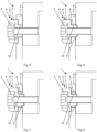
- Figs. 2 and 4-12 are cross-sectional views.
- the OLTC comprises a housing, said housing comprising a housing body 2 and a metal body 3 attached to the housing body 2 using a plurality of fasteners 4.
- Each respective one of said fasteners 4 comprises: a bolt 5 configured to extend from an outside of the housing body 2, through a respective hole of the housing body 2, and to engage with a threaded hole of the metal body 3 on an inside of the housing body 2.
- the fastener 4 further comprises a bushing 6 inserted in the respective hole of the housing body 2, said bushing 6 comprising a central opening through which the bolt 5 extends. Also, the bushing 6 comprises a collar 7 extending around a head of the bolt 5.
- the collar 7 protects the head of the bolt 5, thereby making subsequent service of the OLTC 1 easier by ensuring the bolt head is not damaged and can thus be easily rotated. In other embodiments, the collar 7 may optionally be omitted.
- the bushing 6 provides a smooth interface towards the bolt 5 which mitigates abrasion on the bolt 5 whilst the larger outer diameter of the bushing 6 provides an enlarged wear surface facing the housing body 2.
- the bushing 6 is made of an electrically conductive material.
- the electrically conductive properties of the bushing 6 enables the collar 7 to improve distribution of an electric field extending by the bolt 5/bushing 6.
- the screw is made from an isolation material, such as a ceramic material or a fibre-composite material, a collar is typically not needed on the bushing.
- the bushing 6 may extend into a respective recess 9 of the metal body 3, said recess 9 extending around each respective threaded hole in the metal body 3 and said recess 9 being configured to provide a tight fit with the bushing 6.
- the bushing 6 may optionally instead not engage with a recess of the metal member 3.
- the metal body 3 is a lid of the OLTC 1 configured to cover an open end of the housing body 2.
- the metal body 3 may be any member of the OLTC 1 attached to the housing body 2, such as a bracket or frame.
- the resilient member 8 may be attached to the bushing 6 using moulding or vulcanization. As shown in fig. 10 , the resilient member 8 may alternatively be attached to the housing body 2 on a radial circumference of the respective hole of the housing body 2.
- Affixing the resilient member to either the bushing 6 or the housing body 2 enables more exact positioning of the resilient member 8 and reduces the risk of misplacing the resilient member 8 at manufacturing or maintenance of the OLTC 1.
- the bushing 6 may be provided with a circumferential recess 10, wherein the resilient member 8 extends into said recess 10 and protrudes radially outside of the recess 10 with respect to a central axis of the bolt 5.
- the radially protruding portion of the resilient member 8 will deform elastically upon relative movements between the bushing 6 and the metal member 3. Since the resilient member 8 extends into the circumferential recess 10, a portion of the resilient member 8 within the circumferential recess 10 will also deform, allowing greater movement of the protruding portion of the resilient member 8, which in turn enables use of a tougher material of the resilient member 8, thus increasing resistance to wear of the resilient member 8.
- the resilient member 8 may be formed by any suitable gash et, such as an O-ring or cylindrical member.
- the resilient member 8 may be provided with geometries for engaging with corresponding geometries formed on the bushing 6 and/or on the housing body 2, thus improving alignment of the resilient member 8 with the bushing 6 and/or with the housing body 2.
- the invention is not limited to the specific combination of features illustrated in the examples of the appended figures.
- the recess of the metal body 3 receiving an end of the bushing 6 (examples in figs. 4 and 6-12 ) may be omitted from any of the embodiments in figs. 4 and 6-12 .
- the collar 7 omitted in fig. 12 may be omitted in any embodiment of the bushing 6.
- a washer is typically used between the head of the bolt 5 and the bushing, although that washer may be omitted.
Landscapes
- Engineering & Computer Science (AREA)
- Power Engineering (AREA)
- Insulators (AREA)
Priority Applications (2)
| Application Number | Priority Date | Filing Date | Title |
|---|---|---|---|
| EP23220104.6A EP4576144A1 (de) | 2023-12-22 | 2023-12-22 | Laststufenschalter mit befestigungselement |
| PCT/EP2024/086366 WO2025132116A1 (en) | 2023-12-22 | 2024-12-13 | An on-load tap changer comprising a fastener |
Applications Claiming Priority (1)
| Application Number | Priority Date | Filing Date | Title |
|---|---|---|---|
| EP23220104.6A EP4576144A1 (de) | 2023-12-22 | 2023-12-22 | Laststufenschalter mit befestigungselement |
Publications (1)
| Publication Number | Publication Date |
|---|---|
| EP4576144A1 true EP4576144A1 (de) | 2025-06-25 |
Family
ID=89322008
Family Applications (1)
| Application Number | Title | Priority Date | Filing Date |
|---|---|---|---|
| EP23220104.6A Pending EP4576144A1 (de) | 2023-12-22 | 2023-12-22 | Laststufenschalter mit befestigungselement |
Country Status (2)
| Country | Link |
|---|---|
| EP (1) | EP4576144A1 (de) |
| WO (1) | WO2025132116A1 (de) |
Citations (3)
| Publication number | Priority date | Publication date | Assignee | Title |
|---|---|---|---|---|
| DD159687A1 (de) * | 1981-06-16 | 1983-03-23 | Helmut Kuntzsch | Oelgefaess fuer lastumschalter von stufenschaltern |
| EP0103299A1 (de) * | 1982-09-15 | 1984-03-21 | Maschinenfabrik Reinhausen Gmbh | Zylindrisches Ölgefäss für Stufenschalter von Stufentransformatoren |
| DE4435358A1 (de) * | 1994-09-20 | 1996-03-21 | Siemens Ag | Polsäule eines Hochspannungs-Leistungsschalters |
-
2023
- 2023-12-22 EP EP23220104.6A patent/EP4576144A1/de active Pending
-
2024
- 2024-12-13 WO PCT/EP2024/086366 patent/WO2025132116A1/en active Pending
Patent Citations (3)
| Publication number | Priority date | Publication date | Assignee | Title |
|---|---|---|---|---|
| DD159687A1 (de) * | 1981-06-16 | 1983-03-23 | Helmut Kuntzsch | Oelgefaess fuer lastumschalter von stufenschaltern |
| EP0103299A1 (de) * | 1982-09-15 | 1984-03-21 | Maschinenfabrik Reinhausen Gmbh | Zylindrisches Ölgefäss für Stufenschalter von Stufentransformatoren |
| DE4435358A1 (de) * | 1994-09-20 | 1996-03-21 | Siemens Ag | Polsäule eines Hochspannungs-Leistungsschalters |
Also Published As
| Publication number | Publication date |
|---|---|
| WO2025132116A1 (en) | 2025-06-26 |
Similar Documents
| Publication | Publication Date | Title |
|---|---|---|
| US9638345B2 (en) | Valve apparatus | |
| CN102781189B (zh) | 用于车载电气装置的密封盖和制造方法 | |
| US7690945B2 (en) | Coaxial cable connector for corrugated cable | |
| CN109713513B (zh) | 一种水下穿舱电气连接耐腐蚀密封的装置及其方法 | |
| KR102931992B1 (ko) | 부싱 및 부싱을 포함한 케이블 글랜드 | |
| EP3084905B1 (de) | Verbindungsstück einer verbindereinheit | |
| US10408700B2 (en) | Oil pressure sensor attaching structure | |
| US2821567A (en) | Flexible liquid-tight conduit connectors | |
| US10047788B2 (en) | Ball joint and method of manufacturing the same | |
| US11965560B2 (en) | Bearing assembly | |
| EP4576144A1 (de) | Laststufenschalter mit befestigungselement | |
| CN109786088B (zh) | 一种变压器套管的导电杆端部装配组件及变压器套管 | |
| US20090166506A1 (en) | Engine Mount With Two Piece Core | |
| US9746081B2 (en) | Low load offset seal | |
| US2406852A (en) | Conductor grommet assembly | |
| GB2122714A (en) | Protective routing sleeve for hose assemblies | |
| US20110006518A1 (en) | Compression Seal | |
| US10718372B2 (en) | Dust boot for a moveable joint | |
| CN110725846A (zh) | 一种密封螺母组件 | |
| KR20260052205A (ko) | 패스너를 포함하는 부하시 탭 절환기 | |
| US6156979A (en) | Bushing device and bushing assembly including it | |
| GB2214728A (en) | Mounting cable gland without twisting cable | |
| CN213598462U (zh) | 全密闭电磁刹车器 | |
| CN210576627U (zh) | 可拆卸线束连接座 | |
| US3652782A (en) | Stress relief apparatus for cable connection |
Legal Events
| Date | Code | Title | Description |
|---|---|---|---|
| PUAI | Public reference made under article 153(3) epc to a published international application that has entered the european phase |
Free format text: ORIGINAL CODE: 0009012 |
|
| STAA | Information on the status of an ep patent application or granted ep patent |
Free format text: STATUS: THE APPLICATION HAS BEEN PUBLISHED |
|
| AK | Designated contracting states |
Kind code of ref document: A1 Designated state(s): AL AT BE BG CH CY CZ DE DK EE ES FI FR GB GR HR HU IE IS IT LI LT LU LV MC ME MK MT NL NO PL PT RO RS SE SI SK SM TR |
|
| STAA | Information on the status of an ep patent application or granted ep patent |
Free format text: STATUS: REQUEST FOR EXAMINATION WAS MADE |
|
| 17P | Request for examination filed |
Effective date: 20251022 |
|
| GRAP | Despatch of communication of intention to grant a patent |
Free format text: ORIGINAL CODE: EPIDOSNIGR1 |
|
| STAA | Information on the status of an ep patent application or granted ep patent |
Free format text: STATUS: GRANT OF PATENT IS INTENDED |