EP4576003A2 - Datenkomprimierungs- und dekomprimierungsverfahren und systeme bei der strahlverfolgung - Google Patents
Datenkomprimierungs- und dekomprimierungsverfahren und systeme bei der strahlverfolgung Download PDFInfo
- Publication number
- EP4576003A2 EP4576003A2 EP25168394.2A EP25168394A EP4576003A2 EP 4576003 A2 EP4576003 A2 EP 4576003A2 EP 25168394 A EP25168394 A EP 25168394A EP 4576003 A2 EP4576003 A2 EP 4576003A2
- Authority
- EP
- European Patent Office
- Prior art keywords
- patch
- values
- sub
- tessellation
- ray
- Prior art date
- Legal status (The legal status is an assumption and is not a legal conclusion. Google has not performed a legal analysis and makes no representation as to the accuracy of the status listed.)
- Pending
Links
Images







Classifications
-
- G—PHYSICS
- G06—COMPUTING OR CALCULATING; COUNTING
- G06T—IMAGE DATA PROCESSING OR GENERATION, IN GENERAL
- G06T17/00—Three-dimensional [3D] modelling for computer graphics
- G06T17/20—Finite element generation, e.g. wire-frame surface description, tesselation
- G06T17/205—Re-meshing
-
- G—PHYSICS
- G06—COMPUTING OR CALCULATING; COUNTING
- G06T—IMAGE DATA PROCESSING OR GENERATION, IN GENERAL
- G06T15/00—Three-dimensional [3D] image rendering
- G06T15/04—Texture mapping
-
- G—PHYSICS
- G06—COMPUTING OR CALCULATING; COUNTING
- G06T—IMAGE DATA PROCESSING OR GENERATION, IN GENERAL
- G06T15/00—Three-dimensional [3D] image rendering
- G06T15/06—Ray-tracing
-
- G—PHYSICS
- G06—COMPUTING OR CALCULATING; COUNTING
- G06T—IMAGE DATA PROCESSING OR GENERATION, IN GENERAL
- G06T15/00—Three-dimensional [3D] image rendering
- G06T15/08—Volume rendering
-
- G—PHYSICS
- G06—COMPUTING OR CALCULATING; COUNTING
- G06T—IMAGE DATA PROCESSING OR GENERATION, IN GENERAL
- G06T17/00—Three-dimensional [3D] modelling for computer graphics
- G06T17/20—Finite element generation, e.g. wire-frame surface description, tesselation
-
- G—PHYSICS
- G06—COMPUTING OR CALCULATING; COUNTING
- G06T—IMAGE DATA PROCESSING OR GENERATION, IN GENERAL
- G06T9/00—Image coding
-
- H—ELECTRICITY
- H04—ELECTRIC COMMUNICATION TECHNIQUE
- H04N—PICTORIAL COMMUNICATION, e.g. TELEVISION
- H04N19/00—Methods or arrangements for coding, decoding, compressing or decompressing digital video signals
- H04N19/50—Methods or arrangements for coding, decoding, compressing or decompressing digital video signals using predictive coding
- H04N19/597—Methods or arrangements for coding, decoding, compressing or decompressing digital video signals using predictive coding specially adapted for multi-view video sequence encoding
-
- H—ELECTRICITY
- H04—ELECTRIC COMMUNICATION TECHNIQUE
- H04N—PICTORIAL COMMUNICATION, e.g. TELEVISION
- H04N19/00—Methods or arrangements for coding, decoding, compressing or decompressing digital video signals
- H04N19/90—Methods or arrangements for coding, decoding, compressing or decompressing digital video signals using coding techniques not provided for in groups H04N19/10-H04N19/85, e.g. fractals
- H04N19/94—Vector quantisation
-
- G—PHYSICS
- G06—COMPUTING OR CALCULATING; COUNTING
- G06T—IMAGE DATA PROCESSING OR GENERATION, IN GENERAL
- G06T2210/00—Indexing scheme for image generation or computer graphics
- G06T2210/12—Bounding box
-
- G—PHYSICS
- G06—COMPUTING OR CALCULATING; COUNTING
- G06T—IMAGE DATA PROCESSING OR GENERATION, IN GENERAL
- G06T2210/00—Indexing scheme for image generation or computer graphics
- G06T2210/21—Collision detection, intersection
-
- G—PHYSICS
- G06—COMPUTING OR CALCULATING; COUNTING
- G06T—IMAGE DATA PROCESSING OR GENERATION, IN GENERAL
- G06T2210/00—Indexing scheme for image generation or computer graphics
- G06T2210/36—Level of detail
Definitions
- the present disclosure is directed to techniques of performing compression and decompression of data for use in ray tracing systems.
- Ray tracing is a computational rendering technique for generating an image of a scene (e.g., a 3D scene) by tracing paths of light ('rays') usually from the viewpoint of a camera through the scene. Rays are often traced towards a light source (e.g., shadow rays), though generally are traced towards (potential) scene geometry. For example, primary rays are modelled as originating from the camera and passing through a pixel into the scene. As a ray traverses the scene it may intersect objects within the scene and may also spawn further rays. The interaction between a ray and an object can be modelled to create realistic visual effects.
- a light source e.g., shadow rays
- Rendering an image of a scene using ray tracing may involve performing a large number of intersection tests, e.g., billions of intersection tests.
- the objects themselves are normally represented using a plurality of polygonated 2D surfaces, whose atomic elements are often called 'primitives' (for example, triangles).
- the intersection tests therefore concern the interaction between rays and the primitives used to represent an object. However, it is usually not necessary or helpful to exhaustively perform intersection tests for every ray against every primitive in a scene.
- ray tracing systems can generate acceleration structures, wherein each node of an acceleration structure represents a region within the scene.
- Acceleration structures are often hierarchical (e.g., having a tree structure) such that they include multiple levels of nodes, wherein nodes near the top of the acceleration structure represent larger regions in the scene (e.g., the root node may represent the whole scene), and nodes near the bottom of the acceleration structure represent smaller regions in the scene.
- a "tree node” refers to a node which has pointers to other nodes in the hierarchical acceleration structure, i.e., a tree node has child nodes in the hierarchical acceleration structure.
- a “leaf node” generally refers to a node which has one or more pointers to one or more primitives, i.e., a leaf node does not have child nodes in the hierarchical acceleration structure.
- a leaf node may simply refer to a primitive or list of primitives.
- leaf nodes of the acceleration structure represent regions bounding one or more primitives in the scene.
- the acceleration structure can have different structures in different examples, e.g., a grid structure, an octree structure, a space partitioning structure (e.g., a k-d tree) or a bounding volume hierarchy.
- the nodes can represent suitable shapes or regions in the scene (which may be referred to herein as "boxes").
- the nodes represent axis-aligned bounding boxes (AABBs), or oriented bounding boxes (OBBs), in the scene.
- AABBs axis-aligned bounding boxes
- OOBs oriented bounding boxes
- the overall hierarchy of an acceleration structure may be called a bounding volume hierarchy (BVH), or more generally an acceleration structure (AS).
- the number of primitives that make up an object determines the geometric level of detail (LOD) of that object in the scene.
- LOD geometric level of detail
- the geometric LOD is usually fixed with respect to a contiguous series of frames because the geometric resolution of the scene (and thus the number of primitives used to represent an object) must be known in advance in order to calculate the topology of the acceleration structure.
- Known ray tracing systems cannot dynamically re-adjust the geometric resolution in real time (i.e., per frame).
- the acceleration structures typically used to make real-time ray tracing tractable restrict the geometric LOD in objects within the structure.
- Known methods for adapting the acceleration structure in response to a change in geometric LOD in a ray tracing regime are 'refit' and 'rebuild'.
- the size of the volumes and bounding boxes within the AS is altered. In practice, this involves changing the shapes/volumes/positions of the regions associated with nodes in the AS, e.g., the position of 'split planes', or the extents of bounding volumes in a BVH.
- the outcome of the refit is selected to reduce the number of ray-primitive or ray-box intersection tests.
- the topology and nodal structure of the AS is unchanged, so in particular a refit maintains the same number of nodes.
- a rebuild the entire acceleration structure is rebuilt.
- a rebuild may be performed where a new heuristic is applied to generate the AS, or a previous heuristic may be reapplied to reflect a change in geometric resolution.
- a rebuild may also be performed in response to changes in the scene, such as a change in the geometric LOD of one or models in the scene (e.g., due to the viewing distance to an object being reduced).
- Rebuilding some or all of the AS nodal structure dependent on a dynamic scene is costly, and generally it is not viable on most GPU hardware to perform a rebuild every frame.
- One further method known in ray tracing to change geometric LOD, via a change in texture LOD, is 'tessellation-free displacement mapping'.
- a common way of organising an AS is to implement a (single) high-level AS called a top-level acceleration structure (TLAS), which may contain one or more 'instances' of (one or more) objects each defined using a second AS called a bottom-level acceleration structure (BLAS).
- TLAS top-level acceleration structure
- BLAS bottom-level acceleration structure
- Geometry defined in the TLAS is usually represented in 'world space'
- geometry contained in the one or more BLASs is usually represented in 'instance space' (also called object space).
- object space also called object space
- a TLAS and one or more BLASs make up an AS. This is a convenient way to store objects in world space, e.g., since multiple versions of the same object may be included by inserting pointers to the same BLAS in different locations (optionally with different transformation matrices applied).
- Leaf nodes of a TLAS usually contain a pointer to a single BLAS.
- Leaf nodes of a TLAS may thus be 'instance transform nodes', i.e., nodes requiring a space-coordinate transform from world space to instance space. Therefore, partial rebuilds and partial refits are possible, e.g., where only a subset of BLASs are rebuilt/refitted (resulting in a rebuild/refit of the TLAS also).
- the (partial) refit and (partial) rebuild methods can result in problems with geometric LOD changes, e.g., "popping" of objects as their geometric resolution suddenly changes due to a change in LOD model. Tessellation-free displacement mapping suffers from the fact that watertight rendering cannot be guaranteed in a variety of use cases and is also very reliant on efficient texture sampling.
- Rasterization involves defining a viewing window for a 3D scene containing geometry, and from the viewing window generating a 2D pixel array to be rendered from the 3D scene.
- the rasterised image is generated from models comprising triangular primitives.
- a higher geometric LOD requires a greater number of primitives of generally smaller size.
- Increasing the geometric LOD is beneficial in situations where the primitives of the rasterised scene cover an excessive number of on-screen pixels.
- any tessellated surface is an approximation to the original surface, but the accuracy of this approximation can be improved by increasing the number, and therefore generally decreasing the size, of generated primitives.
- the amount of tessellation/subdivision is usually determined by the geometric LOD at some granularity (e.g., per scene, object/model, face, edge, vertex, material, texture, etc.). However, use of larger numbers of triangles increases the processing effort required to render the scene.
- a patch may be a polygon.
- a patch may be square, rectangular (or a general quadrilateral, e.g., trapezium, parallelogram, or rhombus) or triangular.
- a patch, being polygonal is represented as planar in any space (e.g., world, instance/model/object, view, etc.), the intention may be for the tessellated patch to be curved to accurately map the surface of the represented object, e.g., by having displacement mapping applied to it to form higher-order surfaces.
- the subdivision itself however is not performed in 3-dimensional space (e.g., world, instance/model/object, view, etc.) since this would be computationally inefficient.
- the tessellation is performed in 2-dimensional space, i.e., in the domain of the patch (in which the patch is planar).
- This 2D space may be defined in terms of (u, v) parameters and referred to as 'parametric space' or 'domain space'.
- 'parametric space' or 'domain space' It is customary for the un-tessellated patch to occupy a normalised region in 2D domain space, e.g., the set [0,1] 2 in the case of a quad patch. This advantageously affords simplified computation, e.g., by leveraging fixed-point arithmetic).
- the tessellation process can be made independent of any intended curvature present in the final displaced surface.
- Tessellation in rasterisation regimes may be performed ahead of time, or may be performed on the fly (e.g., on a per-frame basis, to provide continuously varying or view-dependent levels of detail). Suitable methods of tessellation are described in detail in the following disclosure.
- Ray tracing methods are generally not compatible with live (i.e., online/dynamic), e.g., frame-by-frame, geometric LOD updates to scene geometry.
- live i.e., online/dynamic
- ray tracing and their intrinsic acceleration structures, require large amounts of memory, which would make tessellating an entire surface, and necessarily updating the AS on the fly, non-viable.
- the input surface is pre-tessellated at the required geometric resolution prior to the acceleration structure being generated.
- there is a need to rebuild the entire AS e.g., BVH, whenever a change in the geometric resolution occurs (which is not normally feasible to implement in real-time during rendering using most current computer systems).
- a method of compressing data for representing displacement information in a ray tracing system wherein the displacement information indicates displacements to be applied to geometry in a scene to be rendered by the ray tracing system, the method comprising:
- the method may comprise repeatedly performing the encoding for all pairs of values comprised in the pair of datasets, wherein the compressed dataset may comprise compressed displacement information for all information in the pair of datasets.
- the pair of datasets representing displacement information may represent a mipmap having been sampled from texel data representing a texture to be applied to the geometry in the scene.
- the pair of datasets represents displacement information for a particular level of detail, being a geometric or texture level of detail
- the encoded single value representing the identified predetermined condition may be represented with fewer bits than each value of the pair of values.
- the encoded single value may be an unsigned integer.
- the encoded single value may be represented using 2 or 3 bits.
- the pair values are each represented with 8 bits (i.e., a total of 16 bits), wherein each value in the first and second array of values is a normalised integer (in the 8 bit example, between 0 and 255) that may be representative of a normalised floating point value in the range [0, 1].
- the method may comprise compressing a plurality of pairs of datasets representing displacement information to form a plurality of compressed datasets, wherein each compressed dataset of the plurality of compressed datasets may represent a different level of texture detail in the scene to be rendered.
- Each cell of each compressed dataset may be generated in dependence on a plurality of regionally corresponding cells of a compressed dataset having a finer level of texture detail.
- the level of texture detail for each compressed dataset may corresponds to a level of geometric detail.
- the a method may also comprise: decoding the compressed dataset to obtain at least one pair of values representing an upper and lower bound of a magnitude of displacement, wherein the compressed dataset is associated with a patch within the scene; determining a bounding volume that contains the patch, wherein at least one dimension of the bounding volume is determined in dependence on the pair of values; and responsive to determining that the ray intersects the bounding volume, in dependence on tessellation indications associated with the patch, subdividing the patch one or more times to obtain a plurality of patch sub-units.
- the predetermined condition may be that the pair of values is encompassed by a predetermined range of values, wherein the encoded single value may represents the predetermined range.
- the predetermined range may relate to a magnitude of displacement (e.g., the displacement of a primitive).
- One or more values available to encode the pair of values as a single value may be reserved to represent a property of a texture to be applied to the geometry in the scene.
- the predetermined condition may be that the pair of values satisfy a predetermined condition (e.g., both values are zero) indicating a property of the texture, e.g., transparency.
- a predetermined condition e.g., both values are zero
- Some pairs of values may fall within a range, and a different pair of values may represent a special case, e.g., indicating a particular texture property.
- an integrated circuit definition dataset that, when processed in an integrated circuit manufacturing system, configures the integrated circuit manufacturing system to manufacture a hardware unit as described above, or a graphics processing unit as described above.
- the methods described herein may be embodied in a hardware unit.
- a hardware unit for performing compression of decompression described herein.
- an integrated circuit definition dataset that, when processed in an integrated circuit manufacturing system, configures the system to manufacture a hardware unit as described.
- a non-transitory computer readable storage medium having stored thereon a computer readable description of a hardware unit that, when processed in an integrated circuit manufacturing system, causes the integrated circuit manufacturing system to manufacture an integrated circuit embodying a hardware unit as described herein.
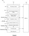
- Figure 1 shows a ray tracing tessellation system 100 comprising a ray tracing unit 102 and a memory 104.
- the ray tracing unit 102 comprises a processing module 106, an intersection testing module 108 and processing logic 110.
- the intersection testing module 108 comprises one or more box intersection testing units 112, one or more primitive (e.g., triangle) intersection testing units 114 (TTU), a tessellation module 116, and an instance transform unit 118 (ITU).
- TTU primitive intersection testing units
- ITU instance transform unit 118
- the intersection testing module 108 may also include one or more procedural tester units (not shown in Figure 1 ) for performing intersection testing with respect to procedural primitives (e.g., those generated programmatically by shader code).
- the ray tracing unit 102 receives geometric data defining objects within the 3D scene.
- the geometric data may comprise geometric data on the patch forming part of the object surface, where the patch is to be tested for intersection and subsequently tessellated.
- the ray tracing unit 102 also receives ray data defining rays that are to be tested for intersection.
- the ray tracing unit also receives tessellation data (also called tessellation indications) indicating how the patch is to be tessellated.
- Figure 1 shows 'tessellation data' being obtained external to the ray tracing unit for simplicity. However, tessellation indications may be obtained from outside and/or inside the ray tracing unit. Thus, in practical examples, the tessellation indications may be partially (or entirely) generated from within the tessellation module 116.
- Tessellation indications generally comprise any data used by the tessellation module 116 to generate new geometry by subdivision. Tessellation indications thus determine the topology (i.e., connectivity) of the final surface.
- Tessellation indications that are generally received externally from ray tracing unit 102 may comprise one or more of: prebaked vertex attributes, samples from a tessellation map/texture, the results of a shader invocation, and some combination thereof. Some or all of these attributes may also be referred to as displacement data, e.g., if they are also used to determine displacement information (e.g., displaced positions of tessellated vertices, or extents of bounding boxes of sub-patches).
- the memory 104 may be local memory used to store a portion of the AS (e.g., one or more BLASs).
- AS e.g., one or more BLASs
- Memory 104 will be utilised to store only as much of the AS that is needed by the ray tracing unit 106 at one time to perform traversal, e.g., enough data to tessellate a particular patch or set of patches.
- Memory 104 may be a local cache.
- pointers may be utilised at the leaf nodes, i.e., such that a BLAS leaf node contains a pointer to any of: a primitive; a list of primitives; a patch; and list of patches.
- BLAS leaf nodes also comprise a bounding volume (which bounds the patch or patches), and patch transform data (i.e., used to apply a transformation from instance space into patch space).
- patch transform data i.e., used to apply a transformation from instance space into patch space.
- the volume (e.g., box) intersection testing unit(s) 112 performs intersection tests to determine whether or not a ray intersects each of the bounding volumes corresponding to nodes of the acceleration structure (where a miss can cull vast swathes of the hierarchical acceleration structure).
- the traversal along the BLAS comprising intersection tests with the bounding volumes (e.g., AABBs), continues until the intersection testing module 108 reaches a node that contains only a bounding volume of a patch, or possibly a small list of patches. This node represents a leaf node in the BLAS.
- bounding volumes or bounding boxes, and the like are, by way of example, presumed to be axis-aligned unless otherwise indicated (e.g., such as an oriented bounding box). If the box intersection testing unit (BTU) indicates a hit with the bounding volume's AABB (fetched from the leaf node of the BLAS) containing the patch, the ray and patch are transformed into a parametric space in which the patch is planar and where the edges of the patch are axis-aligned with the parametric space. In examples, no explicit transformation is performed for the patch, because the space-coordinate system (2D domain space) is derived with reference to the dimension of the patch meaning that the patch becomes implicitly transformed once defined in domain space.
- 2D domain space space-coordinate system
- the instance-space to domain-space transform is specifically chosen such that corner vertices of the patch will be mapped to (algorithmically convenient) predetermined values, e.g., the corners of the patch being mapped to the corners of the set [0,1] 2 , i.e., ⁇ 0,1 ⁇ 2 .
- the ITU 118 that is used to transform from world space to instance space may also be utilised to perform the transform from instance space to patch-based parametric space.
- the attributes of the transform from TLAS to BLAS are stored in (or pointed to by) TLAS leaf nodes, and from BLAS to domain space are stored in (or pointed to by) BLAS leaf nodes.
- the transform information may be explicit (e.g., a matrix transform), or may be derived based on attributes such as corner vertices of a patch. In rasterisation tessellation regimes, such a 2D parametric space may also be referred to as 'domain space'.
- a further 3-dimensional bounding volume/AABB is generated around the 2D patch for testing with the BTU, by extending the parametric domain into 3-dimensional space, such as shown in figure 3 .
- This 3D space is referred to as 'patch space', in which two axes of the space lie within the plane of the patch, and the third axis is orthogonal to the plane of the patch (i.e., parallel to the normal of the patch), or otherwise does not lie in the plane of the patch.
- this AABB is determined according to indicated positive and negative displacement in each axis (which may be a maximal displacement), where this displacement is assumed to be along the direction of the normals associated with each corner vertex of the patch, or along the direction of any normal that may be interpolated from these corner normals.
- the BTU 112 may test a new AABB containing the patch, axis-aligned in respect of the patch space.
- the tessellation module subdivides the patch according to tessellation data. Subsequent intersection tests with the BTU and tessellation operations proceed recursively, dependent on factors such as further 'hits' with new sub-AABBs and the tessellation data. This recursive method of tessellation is described in detail with respect to several examples in the following disclosure, and in figure 5 .
- the recursion proceeds until no more tessellation is required for a given ray, equivalently a sub-patch containing only primitives is reached within the patch wherein the primitives are tested for intersection with the ray, and/or the ray is determined to miss the AABBs of all outstanding sub-patches.
- a new (implicit) hierarchical structure is obtained, which contains the newly-tessellated sub-units of the patch.
- nodes of the hierarchy pertain to sub-patches or sub-triangles (where those sub-triangles are primitives).
- This hierarchy is referred to as a patch-level acceleration structure (PLAS).
- PLAS patch-level acceleration structure
- the PLAS is unique to each ray, i.e., each ray may generate a different hierarchical structure since each ray may induce a different tessellation pattern and/or a different LOD, as a result of different tessellation indications.
- the PLAS is implicitly generated on-the-fly, meaning that it is never fully constructed and stored, but instead partially constructed during traversal.
- a PLAS leaf node is generally a sub-triangle for which no further subdivision can occur, i.e., where the sub-triangle is a primitive.
- the PLAS may be stored in memory and/or cached for subsequent use by other rays.
- a packet of bundled rays, or coherent rays may utilise the same PLAS such that tessellation is not re-performed.
- the triangle intersection testing unit 114 (TTU) performs intersection tests with one or more of the primitives, once they are generated and/or reached during traversal.
- the results of the tessellation and intersection testing are provided to the processing logic 110.
- the processing logic 110 is configured to process the results of the intersection testing to determine rendered values representing the image of the 3D scene.
- the processing logic obtains attribute data to perform the shading, though this is not shown in figure 1 for simplicity.
- the rendered values determined by the processing logic 110 can be passed back to the memory 104, or stored in some other storage area such as global memory (not shown) for storage therein to represent the image of the 3D scene.
- References to LOD (level of detail) in the present disclosure generally refer to a geometric LOD, unless specified as pertaining to another type of LOD (e.g., texture LOD).
- memory 104 shown is generally local memory to the ray tracing module, though in embodiments the processing module 106 and processing logic 110 may store their respective inputs/outputs in any of global memory (not shown) or local memory (such as a local cache) as appropriate, and in a manner that would be derivable by the skilled person.
- the data inputs to the ray tracing unit 108 may actually be received directly from a local memory, e.g., 104 (to improve the efficiency associated with fetching data used for traversing a PLAS), or from another external storage location e.g., global memory.
- Figure 2 shows a patch 204 oriented in object space 210.
- the parallelogram also satisfies
- Reference to model/object space in the following disclosure is interchangeable with 'instance space', and represents the 3D coordinate-space used to represent the geometry of one or more objects sharing a local space, and the patches used to form the surface of those objects.
- the patch 204 in this example is a parallelogram, though other patch configurations (e.g., triangles, or non-parallelograms) are possible as described in the following disclosure.
- the patch 204 is oriented according to object space, i.e., aligned with the surface of an object it is representing.
- the plane of the patch is indicated with respect to patch axes 212. Only one patch is shown, though the surface of an object is represented by a plurality of (usually) contiguous patches (not shown), such that the patches (usually) form a continuous surface with no holes.
- the bounding box 202 shown is axis-aligned with respect to object space axes 210, and is not aligned with the plane of the patch 204.
- Vertices of the patch are V 0 , V 1 , V 2 , and V 3 .
- a ray 208 is indicated which intersects the bounding box 202 at an intersection point 206.
- the bounding box 202 is not configured to tightly bound the 2D patch (i.e., there is free space, e.g., in its normal direction). However, this may be deliberately done, i.e., the object-space bounding box may be arranged to conservatively bound the patch for any combination of tessellation and displacement.
- the bounding box 202 may be constructed to tightly bound an oriented bounding box, OBB, (not shown) that conservatively bounds any tessellated and/or displaced version of the patch.
- the bounding box 202 represents a leaf node of a bottom-level acceleration structure (BLAS), because it contains one or more pointers to one or more patches, i.e., represents regions bounding one or more patches in the scene. Only one patch 204 is shown in figure 2 .
- the ray 208 is tested for intersection with the object-space bounding box 202, preferably by a box testing unit (BTU), as would be understood by a person skilled in the art.
- BTU box testing unit
- the patch 204 will be subsequently tested, after any tessellation of the patch as determined by the tessellation indications, to determine whether the ray intersects sub-patches or primitives generated from the patch by tessellation.
- AABBs aligned with instance space e.g., 202
- resources are not as efficiently utilised due to the degree of misalignment between the plane of the patch and the axes of the instance/object space.
- a new oriented bounding box may be generated in object space (not shown), which is aligned with the plane of the patch and, as mentioned above, conservatively bounds any tessellated and/or displaced version of the patch.
- performing box tests with a non-axis-aligned box may suffer latencies or additional power/area costs that are intrinsic with OBB box tests.
- present embodiments transform the ray into parametric space where, by definition, the edges of the patch are axis-aligned, meaning that a bounding volume can be generated that is axis-aligned and that tightly fits around the patch.
- the bounding volume is constructed in a conservative manner so as to mitigate false-negative hits.
- this allows existing BTUs, e.g., which are already present in the ray-tracing hardware, to be utilised to perform the further intersection tests.
- Box testing against an AABB is also more efficient from an algorithmic perspective than against an OBB. Moreover, box testing with a tightly bound box avoids wasted overlap between bounding volumes of adjacent patches, and thus reduces overall latency. The reduction in latency is more pronounced for smaller patches or sub-patches, i.e., where the extent of displacement applied to the AABB is more significant compared to the size of the patch.
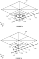
- Figure 3 shows the patch 204 from figure 2 having been transformed into parametric 3D space in which the plane of the patch is aligned with the axes 304 of the space - i.e., patch space.
- the plane of the patch is aligned with the axes 304 of the space - i.e., patch space.
- the present ray tracing embodiments use 3D patch space due to the bounding volumes constructed around the patch.
- the patch 204 is contained within an axis-aligned bounding box 302a (AABB), however this AABB 302a is strictly fitted to the edges of the patch.
- AABB axis-aligned bounding box
- a further, expanded, axis-aligned bounding box 302b is thus generated around the AABB, where the expanded, or 'padded', box is used in examples for the purposes of intersections tests to ensure conservative intersection testing (i.e., to mitigate or avoid false negatives) when displacement along the normals of vertices generated by tessellation is being employed.
- the padded volume 302b is generated, though the tight-fitting box 302a is shown here for illustrative purposes. Padding bounding volumes helps to provide a 'watertight' ray-tracing method and thus avoid artefacts such as cracks in the rendered scene, e.g., resulting from erroneous clipping of displaced primitives.
- the intersection point 308 shown is with respect to padded AABB 302b.
- the patch 204 being a quad, is associated with four vertex normals (306a-d) shown by the four arrows. These indicate the direction of the displacement of the final intersected surface described by the patch. Prior to the final displacement of the primitives, the vertex normals are used, along with a pair of minimum and maximum displacement values, to calculate the padded bounding box (though displacement will not occur if the ray is not found to intersect with any of the lowest level sub-patches within the patch-level acceleration structure). The calculation of padding for bounding volumes according to the present disclosure is described with respect to figure 9 .
- the vertex normals 306a-d encode at least part of the displacement of the primitives contained in the patch, along with the minimum and maximum displacement values.
- Four tessellation factors (TF0, TF1, TF2, TF3) are indicated at the vertices of the patch, which provide the information required to subdivide the patch. These tessellation factors form at least part of (and may form the entirety of) the tessellation indications used by the tessellation module 116.
- a patch is initially associated with four tessellation factors (or generally, one tessellation factor per patch corner vertex).
- tessellation schemes in the present disclosure use tessellation factors that are generated at the per-vertex granularity, however, other examples may generate tessellation factors at other granularities, e.g., per scene, object/model, face, edge, vertex, material, texture, and the like.
- a pre-determined tessellation algorithm determines how subdivision should proceed based on the tessellation factors. Methods of tessellation are described in detail in the following examples.
- the patch 204 is tessellated according to the tessellation indications (TF0, TF1, TF2, TF3) to determine what intersection test to perform next.
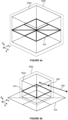
- Figure 4a shows the subdivided patch 204 in patch space, in which the subdivision involves initially subdividing the quad patch into four triangles, and then bisecting each triangle into two sub-triangles within the patch.
- a preferred subdivision operation involves generating a new edge between an existing vertex (for a right-angled triangle, the vertex associated with the right-angled corner) and a point on an existing edge (for a right-angled triangle, the hypotenuse) that bisects that edge into two sub-edges, one for each of the sub-triangles.
- the subdivided patch 204 contains eight sub-units, all of which are triangles, and which themselves can be grouped into four 'sub-patches', i.e., 'sub-quads'.
- the four sub-patches are squares, and thus have the same relative proportions as (i.e., are similar to) the parent patch 204. It may not yet be known whether the triangles are primitives, i.e., whether they are further subdividable. It is not determined at this stage whether the patch sub-units are primitives, since the next step in the algorithm is a box intersection test.
- methods of the present disclosure perform volume-ray intersection tests in preference to primitive-ray intersection tests, because volume-ray tests may be used to rule out a large number of primitives and thus avoid testing excessive primitives. Furthermore, volume-ray tests can be used to rule out unnecessary tessellation. Yet further, volume-ray intersection tests are generally computationally cheaper to perform than primitive-ray intersection tests (in particular when the volume is an AABB). Therefore, it is preferable to increase the ratio of volume-ray tests to primitive-ray tests, and thus to rule out as many expensive primitive tests as possible (which would be performed by the TTU 114) using cheap volume-ray tests performed by a BTU 112.
- an advantage of the present method is that the tessellation (i.e., subdivision) of the patch into sub-patches and/or primitives is performed only on regions of the patch where the ray is determined to intersect.
- this obviates the need to pre-tessellate the entire surface prior to ray tracing, as the traversal of the ray through the patch determines which regions of the patch to tessellate based on which volume-ray intersection tests are successful.
- Figure 4b shows one sub-patch 404 within the larger patch, which contains two triangles.
- a new AABB 402a is formed around the sub patch.
- the AABB 402a of the sub-patch 404 is expanded to form a padded AABB 402b to provide for conservative box-intersection testing (which again provides an inherent watertightness to the final render).
- the sub-AABB for all sub-patches are conservatively constructed in this way (e.g., padded) so that the AABBs for neighbouring sub-patches overlap. This guarantees that a ray which should intersect with a primitive in the patch will also intersect with any sub-patch AABBs higher up the PLAS that are supposed to be bounding it.
- the ray 208 is shown to intersect the padded sub-patch AABB 402b at an intersection point 406.
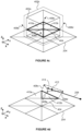
- Figure 4c shows a further level of tessellation having been applied to the sub-patch 404, in response to the 'hit' 406, shown in Figure 4b , between the ray 208 and the padded sub-patch AABB 402b.
- the new tessellation subdivides the two triangles (by bisection) shown in figure 4b to form four new triangles (e.g., 410a, 410b).
- the result of the preferred tessellation step is four triangles of equal size.
- the newly-formed triangles represent a new level of detail in the sense that the patch is now defined with finer granularity.
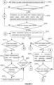
- Figure 5 is a flow chart for a method of performing traversal of a ray through the PLAS associated with a particular ray and patch.
- the method comprises performing box-ray intersections tests and/or tessellation operations and/or primitive-ray intersections tests.
- the flow chart is intended for illustrative purposes only and is not intended to encompass all possible eventualities associated with different patch geometries or tessellation patterns. Certain pathways or groups of steps within the flowchart may also be repeated in a recursive manner. Alternative pathways are thus possible and would be recognised by a person skilled in the art.
- the additional padding value generally corresponds to a small value that almost negligibly increases the extents of the bounding box.
- the functional aim of the additional padding is to ensure watertightness, whilst affecting the latency of the ray tracing to the smallest possible extent.
- the aim of the additional padding is to provide an overlap between bounding volumes of adjacent patches that is small enough not to noticeably impact rendering speed, but which ensures false negative intersection results are avoided.
- the normals of the corner vertices of the patch are generally defined in patch space. These normals can in theory be generated from the instance-space normals and the instance transform on the fly.
- a more computationally efficient method is to generate the corner-vertex normals in patch space offline and subsequently store them as per-patch data (e.g., as part of the BLAS, stored in local memory such as a cache).
- the instance-space normals may be stored elsewhere (e.g., in global memory) and used as shading inputs, whereas the patch-space normals may be stored locally and only used for PLAS traversal.
- the padded AABB e.g., 302b
- the process restarts, via A , and traversal continues along a different pathway (e.g., with a different ray or patch).
- a 'hit' 308 such as indicated in Figure 3 , tessellation of the patch is considered.
- tessellation factors for the patch are obtained. These may comprise tessellation factors, e.g., for each vertex and/or for each edge (and/or possibly a tessellation threshold value).
- tessellation factors e.g., for each vertex and/or for each edge (and/or possibly a tessellation threshold value).
- a positive tessellation factor indicates that some degree of tessellation is required.
- a tessellation factor equal to or less than zero may indicate that the patch should not be tessellated, and may further indicate that the patch should be discarded entirely (i.e., not intersected by any ray).
- Other implementations are possible, and the skilled person will recognise that the meaning associated with different tessellation factor values is implementation-specific.
- tessellation embodiments may shift the position of vertices in parametric/domain space during the generation of new sub-units (e.g., triangles), however, shifting domain-space vertices during subdivision can produce unwanted 'swimming' artefacts in renders after displacement, due to aliasing of the displacement map/function.
- the subdivision maintains the positions of all existing vertices in domain space which has the benefit of avoiding such artefacts.
- the tessellation of a quad patch results in a plurality of initial triangles.
- any hit versus miss for an occluding ray; closest hit versus miss for an non-occluding ray is intended to be the same independent of which branch is followed first (i.e., the result is intended to be deterministic, even if the sequence of volume/primitive testing changes), though the efficiency of the algorithm may depend on the selection of which branch is followed first (e.g., finding an early hit may cull subsequent testing).
- box S512 may never be reached (e.g., where a patch is subdivided into four sub-patches, all of which are missed by the ray). It will be understood by the skilled person that the flow of the method shown in figure 5 is merely exemplary.
- the method determines whether the patch or sub-patch contains any primitives. This step is equivalent to interrogating the tessellation indications to determine whether any further tessellation into primitives is instructed. If it is determined that the (sub-)patch contains no primitives, the method skips via pathway B as if S514 has been answered in the affirmative. In other words, a (sub-)patch that contains no primitives implies that it contains only sub-patches, consistent with an affirmative result in S514. If any primitives are determined to be in the (sub-)patch, then the method continues to S518.
- shading of the primitive is performed, i.e., a shader is triggered for execution (e.g., any-hit shader, closest-hit shader, etc.), with the intersection information (e.g., winding, barycentrics, distance) as input (alongside other data relating to the intersected primitive derived, e.g., interpolated, from the patch per-vertex attributes).
- the results are stored in memory 104 and the traversal continues.
- the sub-patch AABB (e.g., such as the bounding volume 402b in figure 4c ) is tested for intersection with the ray 208.
- the method returns to step S516 to identify a new sub-patch for which to determine a sub-patch AABB and perform a box test.
- the ray 208 missed the AABB 402b in figure 4b , there are three other sub-patches that would be tested for box-ray intersection.
- a 'hit' it is determined what to do next with the sub-patch, e.g., in dependence on the geometric LOD of the sub-patch and any primitives contained within the patch.
- all sub-patches may be tested for volume-ray intersection (at S526), i.e., because a 'hit' AABB may not yield an intersecting primitive (or the closest intersecting primitive for a non-occluding ray), therefore all sub-patches generally are tested for intersection (either upfront in one go, or during a subsequent pass) irrespective of the ray type.
- nodes of the PLAS may be re-used, without having to be regenerated, for subsequent rays for a given patch, and/or for rays bundled together (e.g., for one or more coherent rays).
- Figures 6 and 7 illustrate an alternative embodiment to figure 4 , which shows a method of traversing a PLAS consistent with figure 5 .
- a sub-patch 610 is selected for consideration in the next step.
- step S512 it is determined that the sub-patch does not currently contain any primitives (the two triangular sub-units in the sub-patch 610 may be further subdividable, and thus cannot be deemed primitives at this stage). Since S512 determines that no primitives are present, it is inferred that the sub-patch 610 contains one or more sub-patches to be further subdivided, i.e., it is inferred that S514 is answered in the affirmative. Thus, the method proceeds to step S516 where a new sub-bounding box is generated around the sub-patch 610.
- Figure 6b shows the padded AABB 606b, having been generated around the sub-patch 610 and based on the min/max displacement data and/or vertex normal data, and/or conservatively further padded with an additional padding value.
- the padded sub-patch bounding box 606b is generated in accordance with S516.
- the ray 602 is seen to intersect with the AABB 606b at 'hit' point 608, corresponding to the intersection test at step S526.
- the other three sub-patches have their own sub-patch AABBs that may be generated and tested against the ray 602.
- steps S516 and S526 preferably iterative to test each of the four possible sub-patch AABBs in turn to determine which (if any) intersect with the ray 602.
- pathway D is followed and the new tessellation pattern for the sub-patch 610 is generated (consistent with S510).
- the new tessellation geometry is indicated in figure 6b .
- step S512 it is then determined in accordance with step S512 whether the newly-tessellated sub-patch 610 contains any primitives.
- the local tessellation of the sub-patch 610 shown in figure 6b represents a second LOD.
- S522 determines that all currently-identified primitives within the tessellated sub-patch 610 have been tested.
- the remaining sub-quad 706 is then tested, because step S514 (via branch (2)) is performed either before, after, or concurrently with path (1).
- This sub-patch 706 within a sub-patch 610 may be referred to as a second-order sub-patch.
- Figure 7a shows a second order (axis-aligned) bounding volume 704a (preferably enlarged to a conservatively padded AABB 704b) having been generated around the second order sub-patch 706, in accordance with S516.
- the ray 602 is tested for intersection against the padded sub-AABB 704b.
- the sub-patch 706 does not require further tessellation, and thus implicitly determined (as would be determined in S512) that the second order sub-patch contains primitives (in this case, exclusively primitives).
- the two triangles (710a, 710b in figure 7b ) in sub-patch 706 are primitives and that no more tessellation is required according to the tessellation indications, and by inference determined that the two triangles are primitives (corresponding to a 'yes' at S512).
- step S520 the displaced primitive 712 is tested for intersection with the ray 602 (e.g., by a TTU 114), and a 'hit' 712 is determined. Following the hit, the method proceeds to step S524 for shading of the primitive. Shown according to the dotted arrow after S524, depending on the ray's exit condition, other primitives in the sub-patch (e.g., primitive 710b) may be displaced and tested for intersection with the same (non-occluding) ray 602 even after a hit. Otherwise, following all primitive intersection tests, traversal of a new patch and new corresponding PLAS begins back at step S502 via pathway A.
- primitives in the sub-patch e.g., primitive 710b
- traversal of a new patch and new corresponding PLAS begins back at step S502 via pathway A.
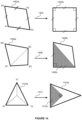
- Figures 8a-8g show seven different local subdivision patterns following a subdivision of a (sub-)patch from one level of detail to a next level of detail.
- all triangles i.e., bounded by solid lines only
- the bold squares are sub-patches that contain a plurality of primitives in some configuration, which may only be found by further subdivision to a higher level of detail.
- Figure 8a shows a minimal tessellation pattern, where the (sub-)patch is bisected between two vertices to form two right angle primitives 800 (and, in some examples, may not be considered a possible initial tessellation pattern for a quad patch).
- Figure 8b has been subdivided to provide four equal-sized primitives 802.
- the tessellation pattern shown in figure 8b is generated by creating a new vertex at the centre of the quad and drawing four new edges between the original vertex corners and the new central vertex.
- Figures 8c and 8d show two (sub-)patches with further subdivisions to produce yet smaller primitives 804 half the size of the primitives 802 in figure 8b .
- the (sub-)patches contain only primitives. If these (sub-)patches were tested consistent with figure 5 , the primitives may be displaced and tested iteratively, i.e., by repeating operation of S518 and S520, including any (intermediate or subsequent) shading necessary. Generally, in the embodiments of this disclosure, sub-triangles (802, 804) that do not collectively form a sub-quad are not further tessellated, and are thus considered primitives.
- All of the sub-triangles formed in figures 8a to 8f are formed after one subdivision operation as per S510, so are of the same geometric LOD, even though the triangles may be of different size (e.g., they differ by a "half" LOD). All triangles in figures 8a to 8f (other than the triangles defined by dashed lines in 8e and 8f) are thus considered primitives because further subdivision cannot occur for them as none of their adjacent sub-triangles can form a sub-patch with them (such as quad 806).
- bounding volumes other than cubic volumes may be created (e.g., prisms for triangular patches, or bounding volumes with simple intersection tests such as spheres).
- cubic bounding boxes e.g., AABBs, OBBs
- this may affect efficiency due to more/less bounding volume hits, because such bounding volumes would either be more or less representative of the underlying patch volume (when fully displaced).
- Figures 8e, 8f show subdivided patches with a mixture of sub-patches 806 and primitives 802, 804.
- the treatment of such patches containing a mixture is consistent with the treatment of the example in figure 6b , i.e., where the sub-patch 610 contains both primitives and a sub-patch 706 around which a bounding box is generated (and where it is not known in the first instance whether the triangles in 706 are primitives or not).
- the primitives are tested for intersection with a ray (i.e., at S518 and S520).
- any sub-patches e.g., such as sub-patch 806 in figure 8e
- each sub-patches each have a bounding volume created around them. This volume is subsequently intersection tested and, if intersected by the ray, the bounded sub-patch is further tessellated.
- the method of iterative tessellation and intersection testing aims to exhaust (i.e., tessellate until no further tessellation operations are indicated) all sub-patches until any non-intersecting sub-patches are ruled out and only primitives remain.
- Figures 6 and 7 imply that primitives generated along the traversal of the PLAS are generally tested first for intersection before testing the sub-patch and (potentially) performing another tessellation step.
- the sub-patch 610 shown in figure 6b replicates the pattern in figure 8e
- the sequence of figures 6 and 7 indicates that the four primitives (804, 802) are intersection tested (e.g., using a TTU 114) first, prior to testing a bounding volume around the sub-patch 706 with a BTU 112.
- This order may be performed, in a serial embodiment, because an early 'hit' with a primitive may help rule out further intersection tests.
- primitive testing (according to path (1) starting with S512 in figure 5 ) is preferably done concurrently with sub-patch testing (according to path (2) starting with step S514 in figure 5 ).
- figures 8a to 8g represent all possible local tessellation patterns (i.e., from one geometric LOD to the next), including both (sub-)patches comprising primitives only, as well as primitive/sub-patch mixtures (which contain primitives that can be grouped into sub-patches, e.g., forming quads).
- Other tessellation methods may have other sets of local tessellation patterns. Therefore, the seven tessellation patterns indicate the seven topological categories (at a given LOD) that may be formed at each stage in the implicit PLAS hierarchy. It is helpful to pre-determine the possible set of nodal structures of a PLAS for memory storage purposes.
- figure 8d represents six primitive nodes
- figure 8f represents 3 primitive nodes and 2 sub-patch nodes.
- the categories shown take account of symmetry. i.e., all possible reflections and rotations of the patterns are accounted for.
- figure 8b has 4-fold rotational symmetry plus reflectional symmetry and therefore only 1 version exists.
- figure 8c has no rotational symmetry but does have reflectional symmetry, and therefore four possible versions exist (all sharing the same nodal structure, i.e., five primitive nodes).
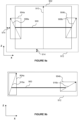
- Figures 9a and 9b show how the patch extents are used to calculate a bounding box around a sub-patch in patch space.
- bounding boxes it would be possible to construct bounding boxes to tightly bound the edges of the patch, e.g., as with the bounding volume 302a around patch 204 in figure 3 .
- tight boxes may not take account of the fact that primitives, once displaced, may protrude the boundary of the tightly bounded box. If the bounding volume does not bound the entire space within which the displaced primitives can exist some intersection tests may result in a 'false negative'.
- a false negative is when an intersection test falsely returns a 'miss' result when in fact the ray should have intersected with the volume (e.g., box) because the ray would have intersected a displaced primitive within that volume.
- False negative results in intersection testing are disadvantageous because they can result in 'cracks' or holes forming in a final render.
- Algorithms which can avoid cracks appearing are referred to as 'watertight'. Consequently, bounding volumes are created in such a way that takes account of the possible extent of displacement of the primitives contained within the bounded patch.
- Patches represented in patch space are planar, and the primitives contained within the patch may not have been formed yet (by tessellation). Also, primitives within the planar patch are thus not displaced into their final 3D position. Therefore, prior to the stage of displacing primitives and triangle-intersection testing (e.g., step S518) it is not known precisely how far outside the boundary of the 2D patch the primitive will lie. Consequently, bounding volumes around patches are padded based on the worst-case displacement of primitives within the patch.
- Figure 9a shows a patch 900 viewed along the XY plane, contained within a bounding box 902 whose faces are flush with the edges of the patch 900.
- the height of the bounding volume 902 is determined by Z min and Z max values which indicate the maximum vertical displacement of a primitive below and above the plane of the patch.
- sub-patches e.g., sub-patch 404 in figure 4b , 610 in figure 6b , and 706 in figure 7a
- these values are a subinterval derived from the original user-supplied interval [Z min , Z max ] and a sequence of predetermined normalised values (e.g., 0 ⁇ 0 and 255 ⁇ 1 for 8-bit values).
- Z min and Z max are used to refer to all min/max ranges at every level of detail, despite the fact that each sub-patch at each LOD represents a different quantized subinterval.
- the min/max displacement values are also region dependent: e.g., the Z min and Z max values for the AABB of the sub-patch 404 in figure 4c may be different to the Z min and Z max values of the AABB surrounding the sub-patch 610 in figure 6b .
- the min/max values for the second order sub-patch 706 in figure 7a are different. Calculation and storage of these values is described with respect to figures 10 and 11 .
- the vertical extents of the bounding volume 910 are all that is needed to form a first bounding volume 902.
- the vertical displacement 910 is calculated by interpolation from the vertex normals 908a, 908b (normals 908a, 908b, and 910 are intended to be the same length, however figure 9a is not drawn to scale for clarity).
- the interpolation is done in figure 9a (and not in figure 9b ) because vertex normals 908a and 908b have opposite horizontal components (i.e., they do not face the same horizontal direction).
- the different directions imply a convex surface, and a 'worst case' vertical normal 910 is calculated based on the vertex normals 908a and 908b.
- the lateral displacement of primitives within the patch must be obtained or conservatively estimated.
- the lateral displacements in respect of the X axis of the patch 900 are notionally indicated by two primitive-displacement boxes 904a, 904b (such boxes may not actually be calculated during generation of the padded bounding volume 912).
- the lateral displacement extents 904a, 904b are indicated by vertex normals 908a, 908b.
- a quad patch will initially be associated with four vertex normals, i.e., one per vertex. New vertex normals are calculated/estimated (e.g., by linear interpolation) for any new vertices generated by tessellation of the patch.
- the vertex normals indicate the direction and magnitude of primitives within the patch and can therefore be used to calculate a 'worst case' primitive displacement. In this way, primitives do not actually have to be displaced to calculate the bounding volume. Moreover, primitives may not yet have been formed by tessellation at this stage, so tessellation is also not required prior to building a bounding volume for a patch or sub-patch.
- All displacement data i.e., the min/max displacement values and the vertex normals
- AS original acceleration structure
- All displacement data are a property of the patch and therefore may be stored with the original acceleration structure (AS) as per-patch data, and may be defined relative to world or instance space.
- AS original acceleration structure
- the magnitude and direction of the vertex normals need to be defined in patch space for PLAS traversal, they may also be transformed into patch/domain space on the fly, prior to calculating the bounding volume extents.
- the displacement data may be stored in the AS defined relative to patch space instead (although world/instance-space normals may still be stored separately for other uses, e.g., as input to rending calculations in shaders).
- the Z axis faces of the tight bounding volume 902 and the lateral-facing faces of the primitive's displacement boxes 904a and 904b can be used to determine the extents of the fully padded bounding volume.
- the generation of padded bounding volumes for patches corresponds to S506 in the case of parent patches, and to S516 in the case of any sub-patches.
- nodes i.e., volumes, primitives
- nodes i.e., volumes, primitives
- This re-use may not be possible for all rays, however, since a PLAS is a function of the ray and therefore may be completely different (apart from the root node) for non-coherent rays.
- references to 'conservative' bounding volumes or 'conservative' AABBs in the present disclosure means a bounding volume that has been expanded or padded along at least one axis to further mitigate false negative tests and therefore ensure watertight rendering.
- some intersection tests may result in a 'false negative' if boxes are not conservatively padded.
- This further padding (corresponding to an additional padding value) is indicated by the small increment 914 shown in figure 9a .
- the additional padding ensures watertightness in the final render by mitigating false negatives during intersection testing.
- the amount is chosen not to be so large as to increase latency (i.e., unnecessarily padded bounding volumes will capture more rays that do not intersect primitives within the patch).
- the small amount 914 may be calculated in a variety of different ways that would be appreciated by the skilled person.
- the additional padding value be a multiple of the machine epsilon, which represents an amount equal to the upper bound on the relative approximation error due to rounding in the floating-point precision used by the volume-ray intersection testing algorithm.
- This type of padding may be particularly suitable for non-zero normal floating-point numbers.
- BTUs 112 implemented in hardware can be implemented with a smaller silicon footprint by reducing the precision used by the hardware, thereby reducing the size of the registers and/or arithmetic operations (e.g., adders, multipliers, etc.) in the hardware.
- This advantage may offset the fact that marginally extended bounding boxes can lead to increased box hits, meaning that slightly less geometry may be culled.
- Figure 10 illustrates one method of generating and storing the min/max displacement data (i.e., Z min and Z max values) used to calculate the extents of bounding volumes 912 as indicated in figures 9a and 9b .
- the patches represented in domain space
- the displacement maps can be correspondingly adapted by adapting the dimensions of the maps (e.g., by affine transformation), as would be recognised by the skilled person.
- the sampled displacement map of texture values 1000 represents a sampling of a texture at the highest possible tessellation level (i.e., the highest texture LOD).
- the map 1000 represents vertical displacement positions.
- the detailed map 1000 in figure 10 is considered normalised to the interval [0, 1] and encoded with eight-bit digits, therefore it can be pre-determined that the lowest and highest values will be 0, considered as the normalised value 0, and 255, considered as the normalised value 1, respectively.
- the values may be stored as unsigned integers to reduce storage requirements.
- cell (1, 7) in the min/max LOD3 grid 1002a/b is '81'/'239' (using an indexing system in which both m and n start at 1), because the lowest/highest value in position 1 7 1 8 2 7 2 8 of the sampled grid 1000 is 81/239 (at the (1,8)/(2,7) position).
- the 9x9 grid of original sampled values 1000 is transformed into 8x8 LOD3 grids 1002a and 1002b.
- the resulting min/max map, at LOD(i) in the min/max mipmap will have dimensions of (2 i ) by (2 i ), for 0 ⁇ i ⁇ n , which advantageously corresponds with geometries produced by the preferred mode of tessellation in this disclosure (which generates new vertices at bisection points, because it is a power of two tessellation scheme).
- the sampled original user-supplied displacement map 1000 advantageously has dimensions (and indices) lining up with the maximum number (and positions) of tessellated vertices at the highest tessellation LOD of the patch.
- each min/max map in the min/max mipmap has dimensions (and indices) lining up with the maximum number (and positions) of bounding volumes at its respective tessellation LOD.
- minimum and maximum tables/grids are calculated from these minimum and maximum 1002a, 1002b grids on the principle of conserving the lowest and highest values for a particular region.
- the two grids for the second highest LOD ('LOD2') have 16 cells each. At this level of granularity, each cell corresponds to a sub-patch the size of a second order sub-patch, e.g., as shown in sub-patch 706 in figure 7a .
- the displacement maps at LOD1 can be calculated as shown in minimum LOD1 map 1006a and maximum LOD1 map 1006b in figure 10 .
- the LOD1 maps have four values each, where each cell corresponds to a sub-patch one quarter the area of a parent patch, e.g., the sub-patch 404 of figure 4b .
- the lowest level of detail ('LOD0') corresponding to a whole patch (e.g., 204), is indicated as a single cell having the value of 0 (corresponding to a normalised 0) for the minimum map 1008a and 255 (corresponding to a normalised 1) for the maximum map 1008b.
- the values for the LODO maps are implicit (i.e., require no storage) in examples where the values are normalised, as they will always corresponding to 0 and 2 n -1 for a n-bit binary value.
- the relevant min/max pair of maps can be stored alongside the patch or sub-patch (e.g., as per-patch data in the AS, or otherwise in a cache), depending on the LOD (e.g., lower LODs, which occupy fewer bytes, may be more suitable as per-patch data), to save time in fetching the displacement data.
- the LOD e.g., lower LODs, which occupy fewer bytes, may be more suitable as per-patch data
- the displacement data 1000 based texture sampling does not need to be interrogated every time a lower LOD displacement value is needed.
- pre-computing all displacement data that may be needed for each LOD increases the efficiency of the traversal, allowing for the possibility of real-time (e.g., frame-by-frame) LOD updates in a ray tracing regime.
- figure 4b is used as an example (although the values in figure 10 are not intended to reflect the actual extents of the AABBs shown in figure 4 ).
- LOD1 first level of detail
- four sub-patches are identifiable within the patch 204, one of which is sub-patch 404. Consistent with S512 of figure 5 , sub-patch 404 is identified and the sub-patch extents are retrieved in order to calculate the dimensions of the AABB.
- a maximum value is read from one cell of LOD1 table 1006b (in this case, 255) and a minimum value is read from the minimum LOD1 table 1006a (in this case, 0). It is therefore determined that the upper face of the bounding volume (Z max ) corresponds to a value of 255, and that the lower face corresponds to a value of 0. Ultimately, these values have been derived from the full (sampled) displacement map 1000, however, the pre-computation of the LOD1 min/max tables means that the Z min and Z max values are simply read from tables 1006a and 1006b respectively.
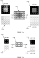
- Figures 11a and 11b illustrate a way of compressing the displacement map data of figure 10 (only LOD2 and LOD1 are illustrated, but an analogous mapping exists for all other LODs, e.g., LOD3).
- the pairs of minimum and maximum displacement dataset values can take up more storage than the detailed map 1000.
- each pair of tables/grids/arrays can be compressed (i.e., quantised) into a single grid having the same number of cells.
- Figure 11a demonstrates this for the LOD2 table of values.
- Grid 1004a represents a set of minimum values for a vertical displacement at LOD2, and 1004b represents corresponding maximum displacement values.
- Each cell in each grid/array corresponds to a cell in the same position in the corresponding grid: e.g., the top-left cell min/max values are 0 and 227 in grids 1004a and 1004b respectively.
- the inventors have identified that each pair of min/max values can be encoded in a single value. Furthermore, the single encoded value may require even fewer bits than each of the original values.
- the pair of 8-bit displacement grids 1004a, 1004b is compressed 1100 in figure 11a to form a compressed LOD2 table 1104 with 16 values.
- data that originally used 32B of storage requires only 4B (sixteen 2-bit values) of storage once compressed, corresponding to a factor of 8 compression.
- max ⁇ 128 and min ⁇ 127 corresponds to [0, 1]
- max,min ⁇ 127 corresponds to [0, 1 ⁇ 2]
- max,min ⁇ 128 corresponds to [1/2, 1].
- the compressed value is encoded as '10'
- the compressed value is encoded as '01'. If the min and max values are not both in the same half of the range (e.g., if max ⁇ 128 and min ⁇ 127) the compressed value is encoded as '00'.
- the compression scheme is nested in that it works down the hierarchy (i.e., from LODO to LOD1 and onwards) during traversal of a PLAS, and is generally performed offline.
- the encoded (compressed) values for each successive LOD make use of the encoded values of previous LODs.
- the interval is updated when transitioning from one LOD to the next.
- An example would be when moving from LODO to LOD1, where the current interval for LODO is [0, 255] (i.e., corresponding to 8-bit values as in 1008b), and the LOD1 encoding for a particular cell is '01'.
- '01' corresponds to max,min ⁇ 127, and the normalised interval of [0, 1 ⁇ 2].
- This result is retained and used as input for the next LOD.
- the decompression scheme also works down the hierarchy during traversal of a PLAS, however the decompression scheme may be performed on-the-fly to benefit from the advantages of compressed data at runtime, such as reduced bandwidth and storage footprints.
- '11' is reserved to indicate some other feature pertaining to the corresponding sub-patch/primitive.
- the value '11' may be reserved to encode transparency/validity information (for example, derived from the alpha channel of a texture), e.g., to allow a ray to immediately skip intersection testing of a primitive or further traversal of a patch sub-quad associated with that value.
- transparency/validity information for example, derived from the alpha channel of a texture
- intersection testing may be immediately avoided (as it is considered fully transparent across the sub-patch and therefore no ray intersection in that subregion should occur.
- the binary encodings are customisable and can be used to represent an arbitrary choice of ranges, provided that the set of encodings include an interval spanning the entire range.
- a 3-bit encoding system i.e., having eight possible values
- the compressed table 1104 may thus be decompressed 1102 according to the inverse of the above formula to provide decompressed minimum LOD2 grid 1106a and decompressed maximum LOD2 grid 1106b. It can be seen that some of the original values in the LOD2 tables 1004a, 1004b have been altered during compression, however, the compression is conservative such that the original minimum values are at worst rounded down, and the original maximum values are at worst rounded up. Consequently, the compressed values still provide displacement values that will generate conservative padded bounding volumes, and thus confer watertightness at least in respect of the box-intersection testing. In some circumstances, the compression results in no loss.
- LOD1 tables 1006a, 1006b are compressed 110 to form a 4x4 compressed grid 1108 with the value '00'.
- the decoded values of the min/max grids 1110a, 1110b are identical to the values in the original grids 1006a, 1006b.
- more precision, and consequently less error is obtained in the compressed values further down the traversal of the hierarchy.
- some LOD grids e.g., LOD1, LOD2 and LOD3 of the compressed min/max mipmap may be storable as part of limited per-patch data in the acceleration structure (AS), and/or more higher LODs may be storable in local memory (e.g., a cache) at one time (due to the reduced footprint).
- AS acceleration structure
- local memory e.g., a cache
- bandwidth and latency are significantly reduced, due to the fact that the number of global memory fetches is reduced overall, which are costly as they have an associated long latency.
- the entire compressed LOD3 table may be fetched in one go, i.e., with a single 16-byte read (in contrast to the eight separate 16B reads required to fetch an uncompressed LOD3 table).
- the forgoing examples describe methods of combining tessellation of a patch with a ray tracing pipeline to generate the LOD required for a given ray on the fly.
- Various methods performing tessellation (i.e., subdivision) of a patch are known in rasterisation embodiments.
- the overall aim of tessellation in any rendering scheme is to produce a tessellation pattern with the desired level of subdivision, per frame, while maintaining the fewest number of visual artefacts and minimal space/time complexity.
- This method has the advantage of avoiding several types of tessellation artefacts including snapping (the effect of large amounts of tessellation occurring instantaneously, known to occur in other discrete, e.g., 'integer' or other 'power of two', methods), popping (the visual artefact where a primitive changed position/orientation suddenly, which mainly arises when newly formed vertices are immediately displaced), cracking or "holes" (where the viewer can see through the object, often as a result of internal T-junctions or inconsistent tessellation at patch edges boundaries), and swimming (where geometry appears to be unstable as a result of the position of a displaced vertex being moved in domain space).
- snapping the effect of large amounts of tessellation occurring instantaneously, known to occur in other discrete, e.g., 'integer' or other 'power of two', methods
- popping the visual artefact where a primitive changed position/orientation suddenly, which mainly arises when newly formed vertices are
- the present tessellation method uses the following parameters: ⁇ 0 ⁇ R ⁇ 0 ⁇ V ⁇ R ⁇ 0
- the tessellation threshold is usually 0.
- the tessellation delta This encodes the amount by which ⁇ V (the tessellation factor) is decremented after each iteration.
- the tessellation delta is usually 0.5 (which, in practice, coincides with one tessellation step representing 'half' of one geometric LOD, i.e., two tessellation steps represent a transition to the next integer LOD).
- ⁇ , f ⁇ R 2 ⁇ R 3 ⁇ R 4 ⁇ R , a symmetric function giving the "average" of two, three or four tessellation factors.
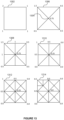
- Figure 12a shows the initial stages of tessellating a quad patch/domain.
- a quad domain 1202 having four vertices labelled TL, TR, BL, BR is fed into a tessellator (such as tessellation module 116).
- a new vertex 1206, M is formed at the centre of the quad.
- the tessellation factor associated with the centre vertex M is given by.
- ⁇ M f ⁇ TL ⁇ TR ⁇ BL ⁇ BR .
- all the tessellation factors associated with of all five vertices is reduced by ⁇ (since one level of tessellation has occurred) to obtain updated tessellation factors.
- each new edge is then created, each between one of TL, TR, BL, BR and the new vertex M.
- four new triangle sub-units are formed within a subdivided quad 1204.
- the four triangle sub-units are then tessellated according to the algorithm, and as shown in figure 12b .
- LOD1 will have been reached. From this stage onwards, each LOD increment will comprise two tessellation steps.
- the quad patch 1202 is a rectangle (preferably a square for numerical convenience) in domain and patch space, though the shape it represents in instance or world space (i.e., in the 3D environment where it forms a portion of an object's surface) may be a different shape (e.g., an arbitrary quad: parallelogram, rhombus, trapezium, kite, delta, irregular quad, etc.). Tessellation is generally performed in domain/patch space, and not in world or instance space.
- a new vertex M is formed as the bisector of the edge LR, i.e., at the point that bisects the longest edge of the triangle 1210.
- the two triangle sub-units in the subdivided unit 1212 are primitives.
- the two triangle sub-units of the subdivided patch 1212 are thus added to the tessellated domain as a primitive (with either a clockwise or anticlockwise convention, inherited from the winding of the patch corner vertices).
- Figure 12c shows the final state of a tessellated quad 1214 whose starting (log-space) tessellation factors are (2, 1, 1, 1), corresponding to vertices ( TL,TR,BL,BR ) .
- the final tessellation pattern of this quad corresponds to the final tessellation pattern of the patch 204 in figure 7b .
- Figure 13 shows an exemplary tessellation of a quad patch consistent with the algorithm described above to generate the pattern in figure 12c , and according to embodiments of the present disclosure.
- the starting quad 1302 is associated with (log-space) tessellation factors (2, 1, 1, 1) as shown.
- the tessellation threshold, ⁇ 0 0.0
- the tessellation delta, ⁇ 0.5.
- a new vertex 1304 is added in the centre of the quad with tessellation factor 1.25 (corresponding to the arithmetic mean calculated using f as described above).
- Four triangle patches are formed in the resulting subdivided unit 1306, corresponding to a first LOD.
- Each tessellation factor for each vertex is then reduced by the tessellation delta, 0.5, though thus can be done before or after formation of the new edges/primitives.
- each of the triangle sub-units in the patch 1306 is subdivided by placing four new vertices in a bisecting position of the edges of the quad. New edges are then generated which connect the new bisecting vertices with each 'top' vertex of each sub-triangle (i.e., corresponding to the centre vertex 1304 of the parent quad patch 1306). Eight new sub-unit triangles are subsequently formed in the new subdivided quad 1308. All tessellation factors of the quad 1308 are then decreased by the tessellation delta, 0.5, as shown in quad 1310 having updated tessellation factors. The resulting subdivided quad 1310 represents a first level of detail (i.e., LOD1).
- the 'bottom' edge of each of the eight sub-triangles is sub-divided (since the tessellation factor of the centre vertex is 0.25, and thus greater than the tessellation threshold of 0) by adding new vertices at the point of bisection (i.e., halfway along the longest edge).
- New tessellation factors are thus calculated for each of the eight new vertices.
- Figure 14 shows three different transforms according to three different patch geometries.
- the patch is a parallelogram 1402a in instance space.
- the parallelogram patch 1402a shown in figure 14 represents a patch in instance or world space, where the diagonal dashes indicate sides having equal lengths.
- the transform of patch 1402a begins with a translation to place one vertex (e.g., P 0 ) at the origin of the instance space coordinates, e.g., the bottom left corner of the square 1402b, corresponding to the origin of coordinate system 210 shown in figure 2 .
- the next step involves applying a matrix transform, M -1 , to the ray, where that transform is a single linear transform .
- M -1 matrix transform
- a single matrix multiplication is applied that preserves lines (collinearity) and parallelism but does not necessarily preserve distance and angles.
- the resulting patch 1402b is preferably a square (i.e., the angles and edge lengths having been transformed, e.g., to right angles and normalised lengths respectively, but the collinearity of the patch is maintained).
- the transform is intentionally constructed to provide convenient 2D coordinates for the patch, thus, the transform is explicitly applied to the ray, but not to the patch.
- the transform of the patch is thus achieved implicitly by having transformed the ray by the inverse matrix described below.
- An arbitrary scale factor may also be applied, by leveraging the degree of freedom in the linear transformation (corresponding to the length of the Z axis in patch-space, i.e., the axis perpendicular to XY domain space).
- the matrix M is given by the three column vectors of x, y, and z.
- the inverse matrix is preferably pre-determined, e.g., computed 'offline' and stored ready for use.
- the values of the matrix can be stored as per-patch data in place of the patch vertex coordinates, which (in domain/patch space) are no longer required as they are embedded in the affine transformation.
- patch-related information is also transformed, e.g., the patch normals used to calculate part of the bounding volumes extents.
- the normals for each vertex of a patch are preferably transformed 'offline' and stored as 'patch-space coordinates' in memory local to the patch. Since the vertex normals for sub-patches are calculated (e.g., by interpolation) from the parent patch data, the transform may be carried out only once for each of the patch vertex normals.
- a non-affine mapping such as a piecewise-affine map
- a non-parallelogram quad patch 1406a may be transformed using a double transformation 1408 into patch space.
- Figure 14 shows a non-parallelogram quadrilateral patch 1406a, e.g., where there are at least three different edge lengths, having vertex coordinates Q 0, , Q 1 ,Q 2 , Q 3 .
- the transformed patch 1406b comprises a portion 1406c (i.e., the right-angled triangle shaded in 1406b) that represents one half of the numerically convenient quad patch in domain space as described above (i.e., where the triangle vertices are aligned with the corners of [0, 1] 2 ).
- One half of the instance-space patch 1406a is transformed to form this portion 1406c, where the other half of the instance space patch has its own transform aligning it with the other half of the numerically convenient quad patch (not shown in figure 14 ).
- the shaded region 1406c (which represents half of a standard (single) quad patch in domain space) is bounded by a standard bounding volume, i.e., a rectangular AABB.
- a standard bounding volume i.e., a rectangular AABB.
- the AABB contains a single triangle rather than a quad/square, and the other (non-shaded) triangle shown in 1406b (as well as any sub-triangles, contained in this triangle, formed by subsequent subdivision of sub-quads along the shared diagonal edge) is culled from consideration (and handled separately with its own transform and bounding volumes, etc.).
- the ray-tracing scheme operates in the same way in terms of intersection testing and tessellation as for a parallelogram quad patch, the difference being that the non-parallelogram quadrilateral patch is handled in a twofold manner, with appropriate masking.
- the shaded portion 1410c represents a right-angled triangle, and occupies a quarter of a quad patch with numerically convenient coordinates, i.e., occupies exactly one sub-triangle of a standard quad patch after initial subdivision.
- this portion 1410c of the transformed triangle patch will preferably have its own transform and be bound by its own AABBs during the ray-tracing process, where tessellation will be handled in the same way as described for the parallelogram embodiments (though in a threefold manner for the triangular patch example).
- At least one tessellation factor of the corner vertices of the triangle patch exceeds the tessellation threshold (e.g., strictly greater than zero) before performing each one of the three piece-wise affine transformations, to ensure that initial subdivision of the triangle patch occurs. Otherwise, no transformation is performed, and the entire triangle patch is tested for intersection with the ray as a single triangle primitive, e.g., by TTU 114.
- the tessellation threshold e.g., strictly greater than zero
- Figure 15 shows a computer system in which the graphics processing systems described herein may be implemented.
- the computer system comprises a CPU 1502, a GPU 1504, a memory 1506, a neural network accelerator (NNA) 1508 and other devices 1514, such as a display 1516, speakers 1518 and a camera 1522.
- a processing block 102 (as in figure 1 ) is implemented on the GPU 1504. In other examples, one or more of the depicted components may be omitted from the system, and/or the processing block 102 may be implemented on the CPU 1502 or within the NNA 1508.
- the components of the computer system can communicate with each other via a communications bus 1520.
- a store 1512 (corresponding to store 104) is implemented as part of the memory 1506.
- the ray tracing system of figure 1 is shown as comprising a number of functional blocks. This is schematic only and is not intended to define a strict division between different logic elements of such entities. Each functional block may be provided in any suitable manner. It is to be understood that intermediate values described herein as being formed by a ray tracing system need not be physically generated by the ray tracing system at any point and may merely represent logical values which conveniently describe the processing performed by the ray tracing system between its input and output.
- the ray tracing units and specifically the intersection testing module and other modules comprised therein including the tessellation module, may be embodied in hardware on an integrated circuit.
- the ray tracing units described herein may be configured to perform any of the methods described herein.
- any of the functions, methods, techniques or components described above can be implemented in software, firmware, hardware (e.g., fixed logic circuitry), or any combination thereof.
- the terms "module,” “functionality,” “component”, “element”, “unit”, “block” and “logic” may be used herein to generally represent software, firmware, hardware, or any combination thereof.
- the module, functionality, component, element, unit, block or logic represents program code that performs the specified tasks when executed on a processor.
- a computer-readable storage medium examples include a random-access memory (RAM), read-only memory (ROM), an optical disc, flash memory, hard disk memory, and other memory devices that may use magnetic, optical, and other techniques to store instructions or other data and that can be accessed by a machine.
- RAM random-access memory
- ROM read-only memory
- optical disc optical disc
- flash memory hard disk memory
- hard disk memory and other memory devices that may use magnetic, optical, and other techniques to store instructions or other data and that can be accessed by a machine.
- Computer program code and computer readable instructions refer to any kind of executable code for processors, including code expressed in a machine language, an interpreted language or a scripting language.
- Executable code includes binary code, machine code, bytecode, code defining an integrated circuit (such as a hardware description language or netlist), and code expressed in a programming language code such as C, Java or OpenCL.
- Executable code may be, for example, any kind of software, firmware, script, module or library which, when suitably executed, processed, interpreted, compiled, executed at a virtual machine or other software environment, cause a processor of the computer system at which the executable code is supported to perform the tasks specified by the code.
- a processor, computer, or computer system may be any kind of device, machine or dedicated circuit, or collection or portion thereof, with processing capability such that it can execute instructions.
- a processor may be or comprise any kind of general purpose or dedicated processor, such as a CPU, GPU, NNA, System-on-chip, state machine, media processor, an application-specific integrated circuit (ASIC), a programmable logic array, a field-programmable gate array (FPGA), or the like.
- a computer or computer system may comprise one or more processors.
- HDL hardware description language
- software which defines a configuration of hardware as described herein, such as HDL (hardware description language) software, as is used for designing integrated circuits, or for configuring programmable chips, to carry out desired functions.
- HDL hardware description language
- a computer readable storage medium having encoded thereon computer readable program code in the form of an integrated circuit definition dataset that when processed (i.e. run) in an integrated circuit manufacturing system configures the system to manufacture a ray tracing system or ray tracing unit configured to perform any of the methods described herein, or to manufacture a ray tracing system or ray tracing unit comprising any apparatus described herein.
- An integrated circuit definition dataset may be, for example, an integrated circuit description.
- a method of manufacturing at an integrated circuit manufacturing system, a ray tracing tessellation system or ray tracing unit as described herein. Furthermore, there may be provided an integrated circuit definition dataset that, when processed in an integrated circuit manufacturing system, causes the method of manufacturing a ray tracing tessellation system or ray tracing unit to be performed.
- An integrated circuit definition dataset may be in the form of computer code, for example as a netlist, code for configuring a programmable chip, as a hardware description language defining hardware suitable for manufacture in an integrated circuit at any level, including as register transfer level (RTL) code, as high-level circuit representations such as Verilog or VHDL, and as low-level circuit representations such as OASIS (RTM) and GDSII.
- RTL register transfer level
- RTM high-level circuit representations
- GDSII GDSI
- one or more intermediate user steps may be required in order for a computer system configured for generating a manufacturing definition of an integrated circuit to execute code defining an integrated circuit so as to generate the manufacturing definition of that integrated circuit.
- the layout processing system 1604 is configured to receive and process the IC definition dataset to determine a circuit layout.
- Methods of determining a circuit layout from an IC definition dataset are known in the art, and for example may involve synthesising RTL code to determine a gate level representation of a circuit to be generated, e.g., in terms of logical components (e.g., NAND, NOR, AND, OR, MUX and FLIP-FLOP components).
- a circuit layout can be determined from the gate level representation of the circuit by determining positional information for the logical components. This may be done automatically or with user involvement in order to optimise the circuit layout.
- the layout processing system 1604 may output a circuit layout definition to the IC generation system 1606.
- a circuit layout definition may be, for example, a circuit layout description.
- the IC generation system 1606 generates an IC according to the circuit layout definition, as is known in the art.
- the IC generation system 1606 may implement a semiconductor device fabrication process to generate the IC, which may involve a multiple-step sequence of photo lithographic and chemical processing steps during which electronic circuits are gradually created on a wafer made of semiconducting material.
- the circuit layout definition may be in the form of a mask which can be used in a lithographic process for generating an IC according to the circuit definition.
- the circuit layout definition provided to the IC generation system 1606 may be in the form of computer-readable code which the IC generation system 1606 can use to form a suitable mask for use in generating an IC.
- the different processes performed by the IC manufacturing system 1602 may be implemented all in one location, e.g., by one party.
- the IC manufacturing system 1602 may be a distributed system such that some of the processes may be performed at different locations, and may be performed by different parties.
- some of the stages of: (i) synthesising RTL code representing the IC definition dataset to form a gate level representation of a circuit to be generated, (ii) generating a circuit layout based on the gate level representation, (iii) forming a mask in accordance with the circuit layout, and (iv) fabricating an integrated circuit using the mask may be performed in different locations and/or by different parties.
- processing of the integrated circuit definition dataset at an integrated circuit manufacturing system may configure the system to manufacture a ray tracing system without the IC definition dataset being processed so as to determine a circuit layout.
- an integrated circuit definition dataset may define the configuration of a reconfigurable processor, such as an FPGA, and the processing of that dataset may configure an IC manufacturing system to generate a reconfigurable processor having that defined configuration (e.g., by loading configuration data to the FPGA).
- an integrated circuit manufacturing definition dataset when processed in an integrated circuit manufacturing system, may cause an integrated circuit manufacturing system to generate a device as described herein.
- the configuration of an integrated circuit manufacturing system in the manner described above with respect to Figure 16 by an integrated circuit manufacturing definition dataset may cause a device as described herein to be manufactured.
- an integrated circuit definition dataset could include software which runs on hardware defined at the dataset or in combination with hardware defined at the dataset.
- the IC generation system may further be configured by an integrated circuit definition dataset to, on manufacturing an integrated circuit, load firmware onto that integrated circuit in accordance with program code defined at the integrated circuit definition dataset or otherwise provide program code with the integrated circuit for use with the integrated circuit.
- performance improvements may include one or more of increased computational performance, reduced latency, increased throughput, and/or reduced power consumption.
- performance improvements can be traded-off against the physical implementation, thereby improving the method of manufacture. For example, a performance improvement may be traded against layout area, thereby matching the performance of a known implementation but using less silicon. This may be done, for example, by reusing functional blocks in a serialised fashion or sharing functional blocks between elements of the devices, apparatus, modules and/or systems.
Landscapes
- Engineering & Computer Science (AREA)
- Physics & Mathematics (AREA)
- General Physics & Mathematics (AREA)
- Theoretical Computer Science (AREA)
- Computer Graphics (AREA)
- Multimedia (AREA)
- Geometry (AREA)
- Software Systems (AREA)
- Signal Processing (AREA)
- Image Generation (AREA)
- Compression, Expansion, Code Conversion, And Decoders (AREA)
Applications Claiming Priority (3)
| Application Number | Priority Date | Filing Date | Title |
|---|---|---|---|
| GB2303378.0A GB2622293B (en) | 2023-03-08 | 2023-03-08 | Data compression and decompression methods and systems in ray tracing |
| GB2303377.2A GB2622292B (en) | 2023-03-08 | 2023-03-08 | Tessellation methods and systems in ray tracing |
| EP24160999.9A EP4429251A1 (de) | 2023-03-08 | 2024-03-01 | Datenkomprimierungs- und dekomprimierungsverfahren und systeme bei der strahlverfolgung |
Related Parent Applications (1)
| Application Number | Title | Priority Date | Filing Date |
|---|---|---|---|
| EP24160999.9A Division EP4429251A1 (de) | 2023-03-08 | 2024-03-01 | Datenkomprimierungs- und dekomprimierungsverfahren und systeme bei der strahlverfolgung |
Publications (2)
| Publication Number | Publication Date |
|---|---|
| EP4576003A2 true EP4576003A2 (de) | 2025-06-25 |
| EP4576003A3 EP4576003A3 (de) | 2025-09-10 |
Family
ID=90123098
Family Applications (3)
| Application Number | Title | Priority Date | Filing Date |
|---|---|---|---|
| EP25168394.2A Pending EP4576003A3 (de) | 2023-03-08 | 2024-03-01 | Datenkomprimierungs- und dekomprimierungsverfahren und systeme bei der strahlverfolgung |
| EP24160999.9A Pending EP4429251A1 (de) | 2023-03-08 | 2024-03-01 | Datenkomprimierungs- und dekomprimierungsverfahren und systeme bei der strahlverfolgung |
| EP24161000.5A Pending EP4428825A1 (de) | 2023-03-08 | 2024-03-01 | Tesselierungsverfahren und systeme in der strahlverfolgung |
Family Applications After (2)
| Application Number | Title | Priority Date | Filing Date |
|---|---|---|---|
| EP24160999.9A Pending EP4429251A1 (de) | 2023-03-08 | 2024-03-01 | Datenkomprimierungs- und dekomprimierungsverfahren und systeme bei der strahlverfolgung |
| EP24161000.5A Pending EP4428825A1 (de) | 2023-03-08 | 2024-03-01 | Tesselierungsverfahren und systeme in der strahlverfolgung |
Country Status (2)
| Country | Link |
|---|---|
| US (2) | US20240303867A1 (de) |
| EP (3) | EP4576003A3 (de) |
Families Citing this family (1)
| Publication number | Priority date | Publication date | Assignee | Title |
|---|---|---|---|---|
| US12626449B2 (en) * | 2023-12-14 | 2026-05-12 | Advanced Micro Devices, Inc. | Ray tracing of displaced micro meshes using a bounding prism hierarchy |
Citations (1)
| Publication number | Priority date | Publication date | Assignee | Title |
|---|---|---|---|---|
| GB2533443B (en) | 2015-06-05 | 2018-06-06 | Imagination Tech Ltd | Tessellation method using recursive sub-division of triangles |
Family Cites Families (8)
| Publication number | Priority date | Publication date | Assignee | Title |
|---|---|---|---|---|
| US8248416B2 (en) * | 2000-06-19 | 2012-08-21 | Mental Images Gmbh | Efficient ray tracing without acceleration data structure |
| GB2539042B (en) * | 2015-06-05 | 2019-08-21 | Imagination Tech Ltd | Tessellation method using displacement factors |
| US10614611B2 (en) * | 2017-04-07 | 2020-04-07 | Intel Corporation | Apparatus and method for implementing bounding volume hierarchy (BVH) operations on tesselation hardware |
| US10825230B2 (en) * | 2018-08-10 | 2020-11-03 | Nvidia Corporation | Watertight ray triangle intersection |
| US11157414B2 (en) * | 2018-08-10 | 2021-10-26 | Nvidia Corporation | Method for efficient grouping of cache requests for datapath scheduling |
| US11995767B2 (en) * | 2020-08-17 | 2024-05-28 | Intel Corporation | Apparatus and method for compressing ray tracing acceleration structure build data |
| US11854138B2 (en) * | 2021-07-23 | 2023-12-26 | Advanced Micro Devices, Inc. | Techniques for introducing oriented bounding boxes into bounding volume hierarchy |
| US12249022B2 (en) * | 2021-09-16 | 2025-03-11 | Nvidia Corporation | Displaced micro-meshes for ray and path tracing |
-
2024
- 2024-03-01 EP EP25168394.2A patent/EP4576003A3/de active Pending
- 2024-03-01 EP EP24160999.9A patent/EP4429251A1/de active Pending
- 2024-03-01 EP EP24161000.5A patent/EP4428825A1/de active Pending
- 2024-03-08 US US18/599,517 patent/US20240303867A1/en active Pending
- 2024-03-08 US US18/599,607 patent/US20240303905A1/en active Pending
Patent Citations (1)
| Publication number | Priority date | Publication date | Assignee | Title |
|---|---|---|---|---|
| GB2533443B (en) | 2015-06-05 | 2018-06-06 | Imagination Tech Ltd | Tessellation method using recursive sub-division of triangles |
Also Published As
| Publication number | Publication date |
|---|---|
| EP4576003A3 (de) | 2025-09-10 |
| US20240303867A1 (en) | 2024-09-12 |
| EP4428825A1 (de) | 2024-09-11 |
| EP4429251A1 (de) | 2024-09-11 |
| US20240303905A1 (en) | 2024-09-12 |
Similar Documents
| Publication | Publication Date | Title |
|---|---|---|
| US12243151B2 (en) | Reduced acceleration structures for ray tracing systems | |
| US11741656B2 (en) | Graphics processing method and system for rendering items of geometry based on their size | |
| US20240078740A1 (en) | Compressed ray direction data in a ray tracing system | |
| CN117280387A (zh) | 用于光线和路径追踪的位移微网格 | |
| CN107657655A (zh) | 在基于图块的图形系统中进行拣出的方法及系统 | |
| EP4099273A1 (de) | Schnittpunktprüfung in einem strahlverfolgungssystem | |
| US20250173948A1 (en) | Intersection Testing in a Ray Tracing System Using Axis-Aligned Box Coordinate Components | |
| EP4113450A1 (de) | Transformation von daten in einem raytracing-system | |
| EP4429251A1 (de) | Datenkomprimierungs- und dekomprimierungsverfahren und systeme bei der strahlverfolgung | |
| US20250131641A1 (en) | Format and mechanism for efficient geometry specification | |
| GB2622293A (en) | Data compression and decompression methods and systems in ray tracing | |
| US12586250B2 (en) | Compression and decompression of sub-primitive presence indications for use in a rendering system | |
| GB2622292A (en) | Tessellation methods and systems in ray tracing | |
| US8031957B1 (en) | Rewritable lossy compression of graphical data | |
| CN117152275A (zh) | 用于渲染系统中的子图元存在指示的压缩和解压缩 | |
| GB2607456A (en) | Intersection testing in a ray tracing system | |
| Wood | Improved isosurfacing through compression and sparse grid orientation estimation | |
| CN117156149A (zh) | 用于渲染系统中的子图元存在指示的压缩和解压缩 | |
| CN117152276A (zh) | 用于渲染系统中的子图元存在指示的压缩和解压缩 | |
| CN117152279A (zh) | 用于渲染系统中的子图元存在指示的压缩和解压缩 |
Legal Events
| Date | Code | Title | Description |
|---|---|---|---|
| PUAI | Public reference made under article 153(3) epc to a published international application that has entered the european phase |
Free format text: ORIGINAL CODE: 0009012 |
|
| STAA | Information on the status of an ep patent application or granted ep patent |
Free format text: STATUS: THE APPLICATION HAS BEEN PUBLISHED |
|
| AC | Divisional application: reference to earlier application |
Ref document number: 4429251 Country of ref document: EP Kind code of ref document: P |
|
| AK | Designated contracting states |
Kind code of ref document: A2 Designated state(s): AL AT BE BG CH CY CZ DE DK EE ES FI FR GB GR HR HU IE IS IT LI LT LU LV MC ME MK MT NL NO PL PT RO RS SE SI SK SM TR |
|
| REG | Reference to a national code |
Ref country code: DE Ref legal event code: R079 Free format text: PREVIOUS MAIN CLASS: G06T0017200000 Ipc: H04N0019597000 |
|
| PUAL | Search report despatched |
Free format text: ORIGINAL CODE: 0009013 |
|
| AK | Designated contracting states |
Kind code of ref document: A3 Designated state(s): AL AT BE BG CH CY CZ DE DK EE ES FI FR GB GR HR HU IE IS IT LI LT LU LV MC ME MK MT NL NO PL PT RO RS SE SI SK SM TR |
|
| RIC1 | Information provided on ipc code assigned before grant |
Ipc: H04N 19/597 20140101AFI20250805BHEP Ipc: H04N 19/94 20140101ALI20250805BHEP Ipc: G06T 15/06 20110101ALI20250805BHEP Ipc: G06T 17/20 20060101ALI20250805BHEP |
|
| P01 | Opt-out of the competence of the unified patent court (upc) registered |
Free format text: CASE NUMBER: UPC_APP_5780_4576003/2025 Effective date: 20250903 |
|
| STAA | Information on the status of an ep patent application or granted ep patent |
Free format text: STATUS: REQUEST FOR EXAMINATION WAS MADE |
|
| 17P | Request for examination filed |
Effective date: 20260305 |