EP4575889A1 - Dispositif d'impression et procédé de commande de dispositif d'impression - Google Patents
Dispositif d'impression et procédé de commande de dispositif d'impression Download PDFInfo
- Publication number
- EP4575889A1 EP4575889A1 EP24221318.9A EP24221318A EP4575889A1 EP 4575889 A1 EP4575889 A1 EP 4575889A1 EP 24221318 A EP24221318 A EP 24221318A EP 4575889 A1 EP4575889 A1 EP 4575889A1
- Authority
- EP
- European Patent Office
- Prior art keywords
- data
- pattern
- medium
- section
- Prior art date
- Legal status (The legal status is an assumption and is not a legal conclusion. Google has not performed a legal analysis and makes no representation as to the accuracy of the status listed.)
- Pending
Links
Images







Classifications
-
- B—PERFORMING OPERATIONS; TRANSPORTING
- B41—PRINTING; LINING MACHINES; TYPEWRITERS; STAMPS
- B41J—TYPEWRITERS; SELECTIVE PRINTING MECHANISMS, i.e. MECHANISMS PRINTING OTHERWISE THAN FROM A FORME; CORRECTION OF TYPOGRAPHICAL ERRORS
- B41J11/00—Devices or arrangements of selective printing mechanisms, e.g. ink-jet printers or thermal printers, for supporting or handling copy material in sheet or web form
- B41J11/008—Controlling printhead for accurately positioning print image on printing material, e.g. with the intention to control the width of margins
-
- B—PERFORMING OPERATIONS; TRANSPORTING
- B41—PRINTING; LINING MACHINES; TYPEWRITERS; STAMPS
- B41J—TYPEWRITERS; SELECTIVE PRINTING MECHANISMS, i.e. MECHANISMS PRINTING OTHERWISE THAN FROM A FORME; CORRECTION OF TYPOGRAPHICAL ERRORS
- B41J3/00—Typewriters or selective printing or marking mechanisms characterised by the purpose for which they are constructed
- B41J3/44—Typewriters or selective printing mechanisms having dual functions or combined with, or coupled to, apparatus performing other functions
- B41J3/445—Printers integrated in other types of apparatus, e.g. printers integrated in cameras
-
- B—PERFORMING OPERATIONS; TRANSPORTING
- B41—PRINTING; LINING MACHINES; TYPEWRITERS; STAMPS
- B41J—TYPEWRITERS; SELECTIVE PRINTING MECHANISMS, i.e. MECHANISMS PRINTING OTHERWISE THAN FROM A FORME; CORRECTION OF TYPOGRAPHICAL ERRORS
- B41J29/00—Details of, or accessories for, typewriters or selective printing mechanisms not otherwise provided for
- B41J29/38—Drives, motors, controls or automatic cut-off devices for the entire printing mechanism
- B41J29/393—Devices for controlling or analysing the entire machine ; Controlling or analysing mechanical parameters involving printing of test patterns
-
- B—PERFORMING OPERATIONS; TRANSPORTING
- B41—PRINTING; LINING MACHINES; TYPEWRITERS; STAMPS
- B41J—TYPEWRITERS; SELECTIVE PRINTING MECHANISMS, i.e. MECHANISMS PRINTING OTHERWISE THAN FROM A FORME; CORRECTION OF TYPOGRAPHICAL ERRORS
- B41J3/00—Typewriters or selective printing or marking mechanisms characterised by the purpose for which they are constructed
- B41J3/407—Typewriters or selective printing or marking mechanisms characterised by the purpose for which they are constructed for marking on special material
-
- B—PERFORMING OPERATIONS; TRANSPORTING
- B41—PRINTING; LINING MACHINES; TYPEWRITERS; STAMPS
- B41J—TYPEWRITERS; SELECTIVE PRINTING MECHANISMS, i.e. MECHANISMS PRINTING OTHERWISE THAN FROM A FORME; CORRECTION OF TYPOGRAPHICAL ERRORS
- B41J3/00—Typewriters or selective printing or marking mechanisms characterised by the purpose for which they are constructed
- B41J3/407—Typewriters or selective printing or marking mechanisms characterised by the purpose for which they are constructed for marking on special material
- B41J3/4078—Printing on textile
-
- B—PERFORMING OPERATIONS; TRANSPORTING
- B41—PRINTING; LINING MACHINES; TYPEWRITERS; STAMPS
- B41J—TYPEWRITERS; SELECTIVE PRINTING MECHANISMS, i.e. MECHANISMS PRINTING OTHERWISE THAN FROM A FORME; CORRECTION OF TYPOGRAPHICAL ERRORS
- B41J3/00—Typewriters or selective printing or marking mechanisms characterised by the purpose for which they are constructed
- B41J3/44—Typewriters or selective printing mechanisms having dual functions or combined with, or coupled to, apparatus performing other functions
-
- G—PHYSICS
- G06—COMPUTING OR CALCULATING; COUNTING
- G06K—GRAPHICAL DATA READING; PRESENTATION OF DATA; RECORD CARRIERS; HANDLING RECORD CARRIERS
- G06K15/00—Arrangements for producing a permanent visual presentation of the output data, e.g. computer output printers
- G06K15/02—Arrangements for producing a permanent visual presentation of the output data, e.g. computer output printers using printers
- G06K15/18—Conditioning data for presenting it to the physical printing elements
- G06K15/1801—Input data handling means
- G06K15/1822—Analysing the received data before processing
-
- G—PHYSICS
- G06—COMPUTING OR CALCULATING; COUNTING
- G06K—GRAPHICAL DATA READING; PRESENTATION OF DATA; RECORD CARRIERS; HANDLING RECORD CARRIERS
- G06K15/00—Arrangements for producing a permanent visual presentation of the output data, e.g. computer output printers
- G06K15/02—Arrangements for producing a permanent visual presentation of the output data, e.g. computer output printers using printers
- G06K15/18—Conditioning data for presenting it to the physical printing elements
- G06K15/1801—Input data handling means
- G06K15/1825—Adapting the print data to an output condition, e.g. object trapping
-
- G—PHYSICS
- G06—COMPUTING OR CALCULATING; COUNTING
- G06K—GRAPHICAL DATA READING; PRESENTATION OF DATA; RECORD CARRIERS; HANDLING RECORD CARRIERS
- G06K15/00—Arrangements for producing a permanent visual presentation of the output data, e.g. computer output printers
- G06K15/02—Arrangements for producing a permanent visual presentation of the output data, e.g. computer output printers using printers
- G06K15/18—Conditioning data for presenting it to the physical printing elements
- G06K15/1835—Transforming generic data
- G06K15/1842—Geometric transformations, e.g. on raster data
- G06K15/1843—Changing size or raster resolution
-
- G—PHYSICS
- G06—COMPUTING OR CALCULATING; COUNTING
- G06K—GRAPHICAL DATA READING; PRESENTATION OF DATA; RECORD CARRIERS; HANDLING RECORD CARRIERS
- G06K15/00—Arrangements for producing a permanent visual presentation of the output data, e.g. computer output printers
- G06K15/02—Arrangements for producing a permanent visual presentation of the output data, e.g. computer output printers using printers
- G06K15/18—Conditioning data for presenting it to the physical printing elements
- G06K15/1848—Generation of the printable image
- G06K15/1852—Generation of the printable image involving combining data of different types
-
- B—PERFORMING OPERATIONS; TRANSPORTING
- B41—PRINTING; LINING MACHINES; TYPEWRITERS; STAMPS
- B41J—TYPEWRITERS; SELECTIVE PRINTING MECHANISMS, i.e. MECHANISMS PRINTING OTHERWISE THAN FROM A FORME; CORRECTION OF TYPOGRAPHICAL ERRORS
- B41J2203/00—Embodiments of or processes related to the control of the printing process
- B41J2203/01—Inspecting a printed medium or a medium to be printed using a sensing device
Definitions
- the present disclosure relates to a printing device and a method for controlling the printing device.
- JP-A-2023-63795 a device is known that acquires surface information about a surface of a medium using an imaging device to adjust an amount of ink, and then prints on the medium.
- the medium may deform as it is transported, for example by stretching, and the pattern may also deform.
- the printing would be shifted with respect to the deformed pattern.
- a printing device includes a transport section that transports a medium having a pattern; an imaging section that captures an image of the medium; a printing section that performs printing on the medium; and a control section that performs a print process after performing a pre-print process, wherein the control section, as the pre-print process, acquires pattern data that relates to the pattern of the medium and expands print data that is to be printed by the printing section to generate expansion data and, as the print process, acquires captured pattern data that relates to the pattern of the medium captured by the imaging section, generates, based on the captured pattern data, conversion data based on the expansion data, and prints the conversion data on the medium using the printing section.
- a method for controlling a printing device that includes a transport section that transports a medium having a pattern, an imaging section that captures an image of the medium, and a printing section that performs printing on the medium, and performs a print process after performing a pre-print process
- the method for controlling the printing device includes, as the pre-print process, acquiring pattern data that relates to the pattern of the medium and expanding print data that is to be printed by the printing section to generate expansion data, and, as the print process, acquiring captured pattern data that relates to the pattern of the medium captured by the imaging section, generating, based on the captured pattern data, conversion data based on the expansion data, and printing the conversion data on the medium using the printing section.
- the positive direction of a Z-axis is referred to as an upward direction, upward, or simply up
- the negative direction is referred to as a downward direction, downward, or simply down
- the positive direction of an X-axis is referred to as a right direction, right side, or simply right
- the negative direction is referred to as a left direction, left side, or simply left
- the positive direction of a Y-axis is referred to as a rear direction, rear side, or simply rear
- the negative direction is referred to as a front direction, front side, or simply front.
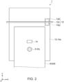
- a printing device 1 includes a control section 10, a storage section 11, a printing section 12, a transport section 13, an imaging section 14, and an input and output section 15. With reference also to FIGS. 2 and 3 , a configuration of the printing device 1 will be described.
- the control section 10 includes a central processing unit (CPU) that integrally controls the respective sections of the printing device 1, a universal asynchronous receiver transmitter (UART) that manages input and output, a field programmable gate array (FPGA) that is a logic circuit, a programmable logic device (PLD), and the like.
- the CPU is also referred to as a processor.
- the storage section 11 includes a flash read only memory (ROM) or a hard disk drive (HDD) which is a rewritable non-volatile memory, a random access memory (RAM) which is a volatile memory, and the like.
- the CPU of the control section 10 reads a program such as firmware stored in the nonvolatile memory of storage section 11 and executes the program using the RAM of storage section 11 as a working area.
- the control section 10 and the storage section 11 are mounted on a circuit substrate (not shown).
- a medium M shown in FIGS. 2 and 3 is, for example, a long cloth made of natural fibers or synthetic fibers.
- the long cloth is also called a roll of cloth.
- the printing device 1 performs printing on the medium M.
- "Printing on cloth” is also referred to as textile printing, and the medium M is also referred to as textile to be printed on.
- the medium M may be any of plain paper, synthetic paper, film, and the like.
- the carriage 12b includes a carriage motor (not shown).
- the head 12a is mounted on the carriage 12b. Head 12a can move reciprocally to the left and right directions above the medium M, which is placed on the transport belt 13a, together with carriage 12b by the carriage motor.
- the head 12a ejects ink droplets from the nozzles onto the medium M while moving above the medium M under control based on print data by the control section 10, and performs printing.
- the print data is stored in the storage section 11.
- the print data may be acquired from an external device such as a computer that is connectable to the printing device 1.
- the imaging section 14 is configured with a camera that has a solid-state imaging element, such as a charge coupled device (CCD) image sensor. Further, the imaging section 14 may be equipped with a lighting device.
- the imaging section 14 is located at a position above the transport belt 13a and facing the transport belt 13a.
- the imaging section 14 can capture an image of the medium M placed on the transport belt 13a. As shown in FIG. 3 , the imaging section 14 can capture at least an entire width of the right and left sides of the medium M. As shown in FIG. 2 , the imaging section 14 is located upstream of the printing section 12.
- the imaging section 14 can capture the pattern P of the medium M before being printed by the printing section 12.
- control section 10 of the printing device 1 performs a predetermined process on print data D0 before the printing section 12 attempts to print the print data D0.
- FIGS. 5 to 11 a control of pre-print process executed by the control section 10 will be described.
- the control section 10 acquires the pattern data P (S100).
- the pattern data P is information relating to the pattern P of the medium M.
- the pattern data P is, for example, CAD data including information indicating a position and a shape of the pattern P in the medium M.
- the pattern data P shown in FIG. 5 is data corresponding to the pattern P of the medium M shown in FIG. 2 , and is denoted by the same reference numerals for convenience of explaining in correspondence with the pattern P of the medium M.
- the control section 10 performs a binarization process on the acquired pattern data P, and sets a first feature point related to an edge of the pattern data P that was subjected to the binarization process. At this time, the control section 10 may perform a smoothing process on the pattern data P that was subjected to the binarization processing.
- the control section 10 can display the pattern data P that was subjected to the binarization process by the input and output section 15, and can set the first feature point by detecting the operation of the user.
- the storage section 11 may store an algorithm for setting the first feature point.
- the control section 10 can read the algorithm from the storage section 11 and execute it, and can set the first feature point.
- the control section 10 may set the first feature point by an external device.
- the print data D0 has first print data D10 that is located within the pattern data P.
- the print data D0 also has second print data D20, which is blank data located within the pattern data P and within the first print data D10.
- the print data D0 is superimposed on the pattern data P shown in FIG. 5 .
- the outer periphery of the pattern data P and the outer periphery of the first print data D10 have the same position and shape.
- the print data D0 has third print data D30 that is located outside the pattern data P.
- the third print data D30 includes third A print data D30a that is located on the left and third B print data D30b that is located on the right.
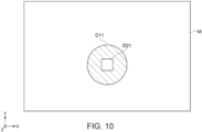
- the control section 10 separates the print data D0 (S102). Specifically, the control section 10 separates the third print data D30 that is outside the pattern data P from the print data D0 as shown in FIG. 7 . The third print data D30 is located outside the pattern data P and does not overlap with the pattern data P. The control section 10 also separates the first print data D10 within the pattern data P from the print data D0 as shown in FIG. 9 . The first print data D10 is located within the pattern data P and overlaps with the pattern data P. If the print data D0 has second print data D20, which is located within the first print data D10, the control section 10 separates the second print data D20 together with the first print data D10. In this case, the second print data D20 is also located within the pattern data P and overlaps with the pattern data P.
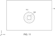
- the control section 10 when the control section 10 expands the first print data D10 to generate the first expansion data D11, the second print data D20 in the pattern data P becomes smaller and contracts to become second reduction data D21. Therefore, as shown in FIG. 11 , the control section 10 corrects the contracted second reduction data D21 so as to replace it with the original second print data D20. In this way, when generating the first expansion data D11, the control section 10 corrects the second print data D20 so that it will be located within the first expansion data D11.
- the third expansion data D31, the first expansion data D11, and the replaced second print data D20 are collectively referred to as expansion data.
- the control section 10 can convert the generated expansion data so that it covers a deformed pattern P (to be described later).
- the control section 10 may, based on the expansion data, use the input and output section 15 to emphasize and display the expanded portion of the original print data D0.
- control section 10 of the printing device 1 performs a print process after the above pre-print process.
- the control section 10 can start the print process based on the user's operation of the input and output section 15.
- the control section 10 can perform the above pre-print process in advance using the time until the user operates the input and output section 15.
- FIGS. 13 to 18 show conceptual diagrams of the medium M when data in a process of being processed by the control section 10 is reflected on the captured medium data MS, which is a captured image of the medium M. Similar to the pre-print process above, the control section 10 can write and read each set of data to and from the memory address of the storage section 11 so as to correspond to the conceptual diagrams of FIGS. 13 to 18 . Note that in the following description, it is omitted that the control section 10 writes and reads each set of the data from the storage section 11.
- the control section 10 acquires the captured pattern data PS that was captured by the imaging section 14 (S200). Specifically, the control section 10 transports the medium M in the transport direction by the transport section 13, captures an image of the pattern P of the medium M using the imaging section 14, and acquires the captured medium data MS and the captured pattern data PS as shown in FIG. 13 .
- the control section 10 generates, based on the acquired captured pattern data PS, conversion data based on the expansion data that was generated in the above pre-print process (S201). More specifically, the control section 10 performs affine transformation on the expansion data to generate the conversion data.
- Affine transformation is a transformation, such as rotation, movement, deformation, expansion, and contraction, of data that is target of processes. The following is a specific explanation of the affine transformation process of the control section 10.
- the medium M and the pattern P When the medium M is transported by the transport section 13, the medium M and the pattern P may be stretched or bent by being pulled, and may be deformed such as by rotation, movement, deformation, expansion, or contraction. Then, the captured medium data MS and the captured pattern data PS, which were captured by the imaging section 14, also become values reflecting the deformation. Specifically, the captured pattern data PS, which was actually captured by the imaging section 14, may be deformed by rotation, movement, expansion, contraction, or the like, compared to the pattern data P, which is the CAD data used to weave the medium M shown in FIG. 5 .
- the captured pattern data PS shown in FIG. 13 shows, as an example of deformation, a case where the pattern data P is stretched and expanded in the transport direction.
- the control section 10 performs the binarization process on the acquired captured pattern data PS.
- the control section 10 extracts a second feature point that corresponds to the first feature point that was set in the pre-print process, from the captured pattern data PS that was subjected to the binarization process.
- the control section 10 may perform a smoothing process on the captured pattern data PS that was subjected to the binarization process.
- the control section 10 can calculate a correction amount for the affine transformation, which includes transformations such as rotation, movement, deformation, expansion, or contraction.
- the pattern data P shown in FIG. 5 is stretched and expanded in the transport direction.
- the correction amount of the affine transformation is a correction amount such that it stretches and expands in the transport direction.
- the control section 10 performs the affine transformation on the expansion data based on the calculated correction amount of the affine transformation to generate the conversion data (S201). In other words, the control section 10 performs the affine transformation on the expansion data so as to correspond to the deformed captured pattern data PS, and generates the conversion data.
- the control section 10 also corrects the generated conversion data (S202).
- control section 10 can perform the affine transformation on a region such that covers the deformed captured pattern data PS.
- the affine transformation for the third expansion data D31 and the first expansion data D11 will be described in order.
- the correction of the generated conversion data will also be described.
- the control section 10 performs the affine transformation on the third expansion data D31, and generates third expansion conversion data DS31 shown in FIG. 14 (S201).
- the third expansion conversion data DS31 includes third A expansion conversion data DS31a that was obtained by affine transformation of the third A expansion data D31a, and the third B expansion conversion data DS31b that was obtained by affine transformation of the third B expansion data D31b.
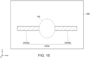
- the control section 10 virtually superimposes the captured pattern data PS on the third expansion conversion data DS31.
- the control section 10 corrects the third expansion conversion data DS31 so as to remove third elimination data DS32, which is an overlapping portion that overlaps with the captured pattern data PS (S202), and obtains the third conversion data DS30 shown in FIG. 15 .
- the third elimination data DS32 includes third A elimination data DS32a and third B elimination data DS32b.
- the control section 10 corrects the third A expansion conversion data DS31a so as to remove the third A elimination data DS32a from the third A expansion data DS31a, and then obtains third A conversion data DS30a as shown in FIG. 15 .
- the control section 10 corrects the third B expansion conversion data DS31b so as to remove the third B elimination data DS32b from the third B expansion data DS31b, and then obtains third B conversion data DS30b as shown in FIG. 15 .
- the control section 10 performs the affine transformation on the first expansion data D11 to generate first expansion conversion data DS11 (S201).
- the first expansion conversion data DS11 indicates the inside of the outermost circumference of the ellipse.
- the control section 10 virtually superimposes the captured pattern data PS on the first expansion conversion data DS11.
- the control section 10 corrects the first expansion conversion data DS11 so as to remove the first elimination data DS13, which is a portion protruding outward from the captured pattern data PS (S202).
- the first elimination data DS13 is a ring-shaped portion between the outer periphery of the first expansion conversion data DS11 and the outer periphery of the captured pattern data PS. Note that in FIG. 16 , for convenience of explanation of the first elimination data DS13, which protrudes outward from the captured pattern data PS, second conversion data DS20 (to be described later) is covered and hidden by the captured pattern data PS.
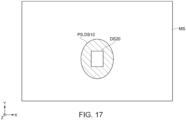
- FIG. 17 shows the first conversion data DS10 obtained by removing the first elimination data DS13 from the first expansion conversion data DS11.
- the outer circumference and the size of the captured pattern data PS are the same as those of the first conversion data DS10.
- the control section 10 places the second conversion data DS20 obtained by affine transformation of the second print data D20, which was replaced in the pre-print process, in the first conversion data DS10.
- the control section 10 combines (S203) the first conversion data DS10 and the second conversion data DS20, which are within the captured pattern data PS, and the third conversion data DS30, which is outside the captured pattern data PS, to obtain the conversion data DS.
- the control section 10 expands and corrects each of the print data D0, which was separated into the inside and the outside of the pattern data P, then in the print process, the control section 10 performs affine transformation to correct them and combines them to obtain the conversion data DS.
- the control section 10 virtually superimposes the conversion data DS on the captured pattern data PS. Therefore, the captured pattern data PS appears on the second conversion data DS20, which is the blank data.
- the control section 10 prints the conversion data DS on the medium M by the printing section 12 (S 204). Specifically, the control section 10 uses the transport section 13 to transport the medium M in the transport direction, and uses the printing section 12 to print the conversion data DS on the medium M. As described above, at this time, the control section 10 captures the pattern P of the medium M by using the imaging section 14. In the print process, the control section 10 can sequentially acquire the captured pattern data PS on the upstream side in the transport direction to generate the conversion data DS, and can print the conversion data DS.
- the control section 10 may print the conversion data DS on the medium M using the printing section 12 while transporting the medium M in the transport direction using the transport section 13.
- the control section 10 may use the imaging section 14 to capture an image of the pattern P of the medium M while using the transport section 13 to transport the medium M in the transport direction.
- the control section 10 simultaneously executes, with respect to the medium M, transport using the transport section 13, printing using the printing section 12, and capturing using the imaging section 14.
- the control section 10 may print the conversion data DS on the medium M by repeating printing using the printing section 12 after transporting the medium M in the transport direction for a predetermined length using the transport section 13.
- the imaging section 14 can capture the pattern P of the medium M whose transportation is stopped while the printing section 12 is printing.
- the imaging section 14 can also capture the pattern P of the medium M being transported when the printing section 12 is not printing.
- FIG. 18 can also be shown as corresponding to the result of the control section 10 that actually printed the conversion data DS on the medium M using the printing section 12.
- the captured medium data MS and the captured pattern data PS in FIG. 18 can be shown as corresponding to the deformed medium M and pattern P.
- the conversion data DS in FIG. 18 including the first conversion data DS10, the second conversion data DS20, and the third conversion data DS30, can be shown as corresponding to the print result.
- the control section 10 can generate and print the conversion data DS in accordance with the pattern P of the deformed medium M.
- the printing device 1 is provided with the transport section 13 that transports the medium M having the pattern P, the imaging section 14 that captures the medium M being transported by the transport section 13, the printing section 12 that performs printing on the medium M, and the control section 10 that performs the print process after the pre-print process.
- the control section 10 acquires pattern data P relating to the pattern P of the medium M and generates expansion data using expanding print data D0 to be printed by the printing section 12.
- the control section 10 acquires captured pattern data PS relating to the pattern P of the medium M captured using the imaging section 14, generates, based on the captured pattern data PS, the conversion data DS based on the expansion data, and uses the printing section 12 to print the conversion data DS on the medium M.
- the printing device 1 attempts to print the print data D0 in accordance with the pattern P of the medium M or at a position corresponding to a position of the pattern P. If the control section 10 prints the print data D0 on the deformed medium M as it is, the print position of the print data D0 may be shifted from an intended position with respect to the deformation pattern P.
- the printing device 1 of the above embodiment it is possible to generate and print the conversion data DS in accordance with the pattern P of the deformed medium M. Therefore, it is possible to suppress printing from being shifted from the intended position with respect to the deformed pattern P.
- the pattern P of the medium M may be printed in advance on the opposite surface of the printing surface of the medium M.
- the control section 10 may first process the first print data D10 within the separated pattern data, and then process the third print data D30 outside the separated pattern data P.
- the control section 10 may first process the first expansion data D11 within the separated pattern data, and then process the third expansion data D31 outside the separated pattern data P.
- a method other than affine transformation may be used.
- a non-linear transformation such as a projective transformation, a B-spline method, or a Thin-plate spline method may be used.
Landscapes
- Engineering & Computer Science (AREA)
- General Engineering & Computer Science (AREA)
- Physics & Mathematics (AREA)
- General Physics & Mathematics (AREA)
- Theoretical Computer Science (AREA)
- Textile Engineering (AREA)
- Image Processing (AREA)
- Accessory Devices And Overall Control Thereof (AREA)
- Record Information Processing For Printing (AREA)
- Ink Jet (AREA)
Applications Claiming Priority (1)
| Application Number | Priority Date | Filing Date | Title |
|---|---|---|---|
| JP2023216596A JP2025099712A (ja) | 2023-12-22 | 2023-12-22 | 印刷装置、及び、印刷装置の制御方法 |
Publications (1)
| Publication Number | Publication Date |
|---|---|
| EP4575889A1 true EP4575889A1 (fr) | 2025-06-25 |
Family
ID=93926581
Family Applications (1)
| Application Number | Title | Priority Date | Filing Date |
|---|---|---|---|
| EP24221318.9A Pending EP4575889A1 (fr) | 2023-12-22 | 2024-12-18 | Dispositif d'impression et procédé de commande de dispositif d'impression |
Country Status (4)
| Country | Link |
|---|---|
| US (1) | US20250206050A1 (fr) |
| EP (1) | EP4575889A1 (fr) |
| JP (1) | JP2025099712A (fr) |
| CN (1) | CN120191133A (fr) |
Citations (7)
| Publication number | Priority date | Publication date | Assignee | Title |
|---|---|---|---|---|
| US20030161002A1 (en) * | 2002-02-27 | 2003-08-28 | Hirofumi Nishiwaki | Image formation apparatus and method, charge counting device, charging method, and computer products |
| US20050041087A1 (en) * | 2003-08-19 | 2005-02-24 | Funai Electric Co., Ltd. | Photoprinter printing image on recording paper |
| JP2006098727A (ja) * | 2004-09-29 | 2006-04-13 | Fuji Photo Film Co Ltd | 伸縮状態の検出手段を設けた長尺の可撓性記録媒体と、この可撓性記録媒体に伸縮状態を補正して画像を描画可能な描画方法及び装置 |
| US20210162776A1 (en) * | 2019-11-28 | 2021-06-03 | Seiko Epson Corporation | Printing apparatus and printing method |
| US20210221152A1 (en) * | 2018-09-21 | 2021-07-22 | SCREEN Holdings Co., Ltd. | Printing apparatus |
| JP2023063795A (ja) | 2021-10-25 | 2023-05-10 | ブラザー工業株式会社 | 液滴吐出装置、液滴吐出方法および液滴吐出プログラム |
| US20230166933A1 (en) * | 2021-11-30 | 2023-06-01 | Nidec Sankyo Corporation | Medium issuing device, medium issuing system and medium issuing method |
-
2023
- 2023-12-22 JP JP2023216596A patent/JP2025099712A/ja active Pending
-
2024
- 2024-12-18 EP EP24221318.9A patent/EP4575889A1/fr active Pending
- 2024-12-19 CN CN202411883039.2A patent/CN120191133A/zh active Pending
- 2024-12-20 US US18/990,475 patent/US20250206050A1/en active Pending
Patent Citations (7)
| Publication number | Priority date | Publication date | Assignee | Title |
|---|---|---|---|---|
| US20030161002A1 (en) * | 2002-02-27 | 2003-08-28 | Hirofumi Nishiwaki | Image formation apparatus and method, charge counting device, charging method, and computer products |
| US20050041087A1 (en) * | 2003-08-19 | 2005-02-24 | Funai Electric Co., Ltd. | Photoprinter printing image on recording paper |
| JP2006098727A (ja) * | 2004-09-29 | 2006-04-13 | Fuji Photo Film Co Ltd | 伸縮状態の検出手段を設けた長尺の可撓性記録媒体と、この可撓性記録媒体に伸縮状態を補正して画像を描画可能な描画方法及び装置 |
| US20210221152A1 (en) * | 2018-09-21 | 2021-07-22 | SCREEN Holdings Co., Ltd. | Printing apparatus |
| US20210162776A1 (en) * | 2019-11-28 | 2021-06-03 | Seiko Epson Corporation | Printing apparatus and printing method |
| JP2023063795A (ja) | 2021-10-25 | 2023-05-10 | ブラザー工業株式会社 | 液滴吐出装置、液滴吐出方法および液滴吐出プログラム |
| US20230166933A1 (en) * | 2021-11-30 | 2023-06-01 | Nidec Sankyo Corporation | Medium issuing device, medium issuing system and medium issuing method |
Also Published As
| Publication number | Publication date |
|---|---|
| CN120191133A (zh) | 2025-06-24 |
| US20250206050A1 (en) | 2025-06-26 |
| JP2025099712A (ja) | 2025-07-03 |
Similar Documents
| Publication | Publication Date | Title |
|---|---|---|
| CN112848679B (zh) | 印刷装置以及印刷方法 | |
| US11697290B2 (en) | Printing apparatus and printing method | |
| US20150174925A1 (en) | Printing method, printing apparatus, and computer readable non-transitory recording medium storing printing program | |
| JP7604855B2 (ja) | 印刷装置および印刷方法 | |
| CN108016149B (zh) | 印刷装置以及印刷装置的调整方法 | |
| EP4575889A1 (fr) | Dispositif d'impression et procédé de commande de dispositif d'impression | |
| CN114559753B (zh) | 印刷装置及印刷方法 | |
| US11514279B2 (en) | Printing apparatus for printing image on fabric formed with pattern and printing method for printing image on fabric formed with pattern | |
| JP6895857B2 (ja) | インクジェット印刷装置および濃淡補正方法 | |
| CN114571873B (zh) | 印刷装置及印刷方法 | |
| JP2020082419A (ja) | 画像形成装置、画像形成装置のシェーディング補正方法およびシェーディング補正プログラム | |
| CN119590111A (zh) | 印刷装置以及印刷方法 | |
| US10919310B1 (en) | Methods for operating printhead inkjets to attenuate ink drying in the inkjets during printing operations | |
| US11727234B2 (en) | Performance of printing based on detected end portions of medium | |
| JP7835014B2 (ja) | 印刷装置 | |
| US12377660B2 (en) | Density unevenness correction data creation method, density unevenness correction data creation apparatus, printing system, program, test chart, and test chart data creation apparatus | |
| EP4718833A1 (fr) | Procédé d'impression, appareil d'impression et support d'informations lisible par ordinateur non transitoire stockant un programme | |
| JP2018205239A (ja) | 搬送量検出装置および記録装置 |
Legal Events
| Date | Code | Title | Description |
|---|---|---|---|
| PUAI | Public reference made under article 153(3) epc to a published international application that has entered the european phase |
Free format text: ORIGINAL CODE: 0009012 |
|
| STAA | Information on the status of an ep patent application or granted ep patent |
Free format text: STATUS: THE APPLICATION HAS BEEN PUBLISHED |
|
| AK | Designated contracting states |
Kind code of ref document: A1 Designated state(s): AL AT BE BG CH CY CZ DE DK EE ES FI FR GB GR HR HU IE IS IT LI LT LU LV MC ME MK MT NL NO PL PT RO RS SE SI SK SM TR |
|
| STAA | Information on the status of an ep patent application or granted ep patent |
Free format text: STATUS: REQUEST FOR EXAMINATION WAS MADE |
|
| 17P | Request for examination filed |
Effective date: 20260102 |