EP4575700A1 - Verfahren, system und computerprogramme zur steuerung von multikopterdrohnen - Google Patents
Verfahren, system und computerprogramme zur steuerung von multikopterdrohnen Download PDFInfo
- Publication number
- EP4575700A1 EP4575700A1 EP23217553.9A EP23217553A EP4575700A1 EP 4575700 A1 EP4575700 A1 EP 4575700A1 EP 23217553 A EP23217553 A EP 23217553A EP 4575700 A1 EP4575700 A1 EP 4575700A1
- Authority
- EP
- European Patent Office
- Prior art keywords
- lookahead
- point
- velocity
- arc
- computed
- Prior art date
- Legal status (The legal status is an assumption and is not a legal conclusion. Google has not performed a legal analysis and makes no representation as to the accuracy of the status listed.)
- Pending
Links
Images


Classifications
-
- G—PHYSICS
- G05—CONTROLLING; REGULATING
- G05D—SYSTEMS FOR CONTROLLING OR REGULATING NON-ELECTRIC VARIABLES
- G05D1/00—Control of position, course, altitude or attitude of land, water, air or space vehicles, e.g. using automatic pilots
- G05D1/40—Control within particular dimensions
- G05D1/46—Control of position or course in three dimensions [3D]
-
- G—PHYSICS
- G05—CONTROLLING; REGULATING
- G05D—SYSTEMS FOR CONTROLLING OR REGULATING NON-ELECTRIC VARIABLES
- G05D1/00—Control of position, course, altitude or attitude of land, water, air or space vehicles, e.g. using automatic pilots
- G05D1/20—Control system inputs
- G05D1/22—Command input arrangements
- G05D1/229—Command input data, e.g. waypoints
-
- G—PHYSICS
- G05—CONTROLLING; REGULATING
- G05D—SYSTEMS FOR CONTROLLING OR REGULATING NON-ELECTRIC VARIABLES
- G05D1/00—Control of position, course, altitude or attitude of land, water, air or space vehicles, e.g. using automatic pilots
- G05D1/60—Intended control result
- G05D1/646—Following a predefined trajectory, e.g. a line marked on the floor or a flight path
-
- G—PHYSICS
- G05—CONTROLLING; REGULATING
- G05D—SYSTEMS FOR CONTROLLING OR REGULATING NON-ELECTRIC VARIABLES
- G05D1/00—Control of position, course, altitude or attitude of land, water, air or space vehicles, e.g. using automatic pilots
- G05D1/60—Intended control result
- G05D1/656—Interaction with payloads or external entities
- G05D1/689—Pointing payloads towards fixed or moving targets
-
- G—PHYSICS
- G05—CONTROLLING; REGULATING
- G05D—SYSTEMS FOR CONTROLLING OR REGULATING NON-ELECTRIC VARIABLES
- G05D2109/00—Types of controlled vehicles
- G05D2109/20—Aircraft, e.g. drones
- G05D2109/25—Rotorcrafts
- G05D2109/254—Flying platforms, e.g. multicopters
Definitions
- the present invention relates generally to the field of flight control systems for unmanned aircrafts and specifically to path follower controllers for multicopter drones (i.e. multi-rotor and single-rotor drones).
- Controlling the flight of multicopter drones using traditional pure-pursuit controllers has encountered several limitations. These controllers are primarily designed for twodimensional (2D) path tracking on flat surfaces, restricting their application in three-dimensional (3D) space.
- multicopter are flying at a wide range of velocity.
- Traditional pure-pursuit controllers have difficulties adapting to varying velocities without re-tuning and are often less efficient at high speed.
- Some pure-pursuit controllers attempt to address these issues by using a dynamic lookahead distance based on current velocity.
- they also try to improve performances at high speed by using additional heuristic constraints to regulate the velocity command based on the curvature of the path.
- additional heuristic constraints to regulate the velocity command based on the curvature of the path.
- no controller includes those features for 3D path and according to the specific dynamics of multicopter drones.
- the controller introduces advancements to traditional pure-pursuit techniques, enabling precise 3D path following within an extended velocity range.
- Key features include (1) a path discretization algorithm to select a lookahead point on a 3D path, (2) independent yaw control loop and combined yaw input with linear velocity commands, (3) refined velocity commands using heuristics based on multicopter dynamics and capabilities to cover multicopter velocity range.
- the invention provides improved motion control and enhanced path following capabilities for drones and is specifically tailored for multicopter drone commercial applications
- embodiments of the present invention provide, according to one aspect, a method for controlling multicopter drones, including both multi-rotor and single-rotor drones.
- the method comprises performing by one or more processors the following steps: selecting a lookahead point to a multicopter drone on a given 3D path; computing an angular yaw velocity command using a given yaw input; computing linear horizontal and vertical velocity commands given horizontal and vertical distances to the selected lookahead point and a desired cruise velocity; creating an arc going from the multicopter drone to the selected lookahead point by combining the computed angular yaw velocity command with the computed linear horizontal and vertical velocity commands, and computing a velocity vector command using the created arc; and refining the computed velocity vector command based on previous computed velocity commands and an allowed maximum acceleration.
- the selecting step is done by relying on a dynamic lookahead distance and by discretizing and pruning the given 3D path.
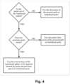
- the lookahead point is selected by computing a lookahead radius using a velocity of the multicopter drone and a lookahead time parameter, and by looking if all the points of the discretized and pruned 3D path are out of the computed lookahead radius, if so, the first point of the pruned path is used as lookahead point p lookahead , otherwise, the first point that is out of the lookahead radius is looked for.
- the last point of the discretized and pruned 3D path is used as lookahead point
- the first point out of lookahead radius is not the first one of the discretized and pruned 3D path
- an intersection point of a lookahead sphere with a segment formed by the intersection point and the previous point is used as lookahead
- the first point out of lookahead radius is the first one of the discretized and pruned 3D path, it is used as lookahead point.
- the method also comprises projecting the created arc onto a 3D cylinder.
- the given yaw input comprises a yaw setpoint and a given gain parameter, the yaw setpoint being obtained from an external source or comprising a point of interest.
- the method also comprises defining a first rotated frame R B using an angle a between a velocity vector in a xy plane, and transforming the selected lookahead point to the defined first rotated frame R B .
- an angle ⁇ can also be used to define a second rotated frame R C around a y-axis.
- the selected lookahead point can be transformed to the defined second rotated frame R C .
- the method can also create a 3D arc from the multicopter drone to this transformed lookahead point, and the computed velocity vector command can be penalized based on the radius of a sphere derived from the created 3D arc. Particularly, this radius is variable/dynamic and depends on the desired cruise velocity. This allows the present invention to be used on a wide range of velocity.
- a computer program product is one embodiment that has a computer-readable medium including computer program instructions encoded thereon that when executed on at least one processor in a computer system causes the processor to perform the operations indicated herein as embodiments of the invention.
- the present invention provides a path follower controller method and system adapted to multicopter drone operation that is able to (1) make a multicopter drone follow a 3D path; (2) while orienting the multicopter drone according to an independent yaw input, and (3) able work on a wide velocity range by using heuristic constraints respecting multicopter dynamics.
- Present invention provides a novel three-dimensional (3D) path follower controller particularly tailored for multicopter drones.
- the invention enables 3D path following within an extended velocity range.
- the invention incorporates vital features essential for multicopter drone operation, including independent yaw control and precise motion at high velocities. To ensure smooth and accurate motion, it uses a dynamic lookahead distance and applies heuristic constraints based on path curvature and drone velocity to regulate velocity commands. Additionally, velocity commands are further refined considering the multicopter's maximum velocity and acceleration, resulting in improved performance.
- present invention is based on the theory of adaptive pure-pursuit controllers and adapts it for the specificity of multicopter drones.
- the invention logic extends the classic 2D pure-pursuit controller to work in 3D in a way that fits multicopter dynamics.
- body frame velocity input to control a multicopter drone only 3D linear velocity and angular yaw velocity can be inputted because roll and pitch angles are not controllable.
- classic pure-pursuit control algorithms require the heading to be constrained and dependent on following the arc from the drone to the lookahead point.
- the present invention uses an extended logic to allow for multicopter drones (and any holonomic robot) to be able to follow a yaw input command while following a given path.
- the present invention extends the existing heuristic constraints used in some pure-pursuit controllers to work in 3D.
- Some pure-pursuit controllers have been using the curvature of the arc going from the drone to the lookahead point to penalize velocity when the radius of the arc is smaller than a previously defined radius.
- the present invention extends the logic by using the curvature of a 3D arc and the radius of the sphere derived from this arc to penalize velocity.
- the minimum arc radius is made dynamic and dependent on the desired cruise velocity.
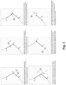
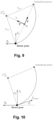
- FIG. 1 and 2 A schematic view of the controller is given in Figs. 1 and 2 , that, according to an embodiment, works by (1) finding a lookahead point on a given 3D paths (in the Lookahead Point Selection block), (2) computing an angular yaw velocity command given a yaw input (in the Yaw Controller block), (3) computing the linear horizontal and vertical velocity commands given the horizontal and vertical distances to the lookahead point and the desired cruise velocity (in the Linear Velocity Computation block), (4) combining both linear and angular velocity to find an arc going from the drone position to the lookahead point, and using this arc to compute a velocity vector command in drone body frame (in the Pure-Pursuit Control block), and (5) refining the velocity command based on previous command and allowed maximum acceleration (in the Command Smoother block).
- the path Before being able to use the path, in some embodiments, the path needs to be transformed into the drone frame of reference and pruned from the closest point. This process is carried out by the Lookahead Point Selection block illustrated in Figs.1 and 2 .
- the selection process of the lookahead point on the previously discretized and pruned path is as follows:
- another adaptation required for going from the 2D controller to a 3D controller is the use of a lookahead sphere instead of a lookahead circle when interpolating the lookahead point on a segment.
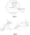
- the intersection point of the sphere and segment is obtained by first looking for the intersecting points between the sphere and the line defined by the segment, and then refining to only get the points on the segment, as shown in Fig. 5 .
- the point P ( x, y, z ) is also at a distance of a radius R to the center of the lookahead sphere:
- the segment is chosen by having one point inside the sphere and another point outside the sphere. Therefore, only one point of the intersection of the line with the sphere is on the segment.
- sphere ( R ) is a sphere of center (0,0,0) and radius R; and ⁇ is found as explained in the section above.
- the path granularity is important. One end of the segment should be inside of the lookahead sphere and the other end outside of it. This is guaranteed by the path pruning and the lookahead point selection process previously executed. Interpolation is always done on a segment formed by a point within the lookahead radius and a point out of the lookahead radius.
- the main loop is itself divided into three elements used to achieve independent yaw control and the pure-pursuit path following.
- a yaw control loop generates a yaw rate command from the yaw setpoint and current yaw of the drone.
- another control loop computes the vertical velocity command and the horizontal velocity command norm, using the lookahead point previously chosen.
- the commands are combined using a pure-pursuit algorithm that traces an arc from the drone to the lookahead point according to the horizontal velocity command norm and yaw rate command.
- the horizontal velocity vector is obtained by computing the tangent vector to the arc with a norm of the commanded horizontal velocity.
- the yaw setpoint also called heading angle
- the yaw rate command ⁇ cmd . may be calculated first by using a proportional controller.
- ⁇ cmd . ⁇ setpoint ⁇ ⁇ ⁇ P angular
- the presented control algorithm computes the linear velocities by extending the classic 2D pure-pursuit algorithm to 3D in a way that satisfies multicopter drone dynamics.
- an arc A is created that joins the robot and a point on the path.
- the point on the path also called lookahead point, is chosen by being the intersection of the path with a circle of a radius of the lookahead distance and centered on the robot.
- the center needs to be on the perpendicular line to the robot forward axis. In 2D, only the rotation around the vertical axis is necessary to follow the arc A.
- the circle defining the arc A is not augmented to a sphere but to a cylinder, as shown in Fig. 6 .
- Some approaches to convert the controller to 3D simply set another controller (PID for example) to control the vertical position separately and then track the projected path in the 2D plane xy.
- PID controller
- the approach taken in the present invention is to set the norm of the 3D velocity vector to the desired linear velocity and then obtain the vertical and horizontal components proportionally.
- v ( v x , v y , v z ) T be the desired velocity vector pointing from the origin (the drone).
- the norm of v is set to the desired linear velocity v desired (also referred as cruise velocity):
- the horizontal linear velocity norm and angular velocities obtained previously are then combined within a pure-pursuit algorithm.
- pure-pursuit algorithms existing in the literature an arc from the drone position to the projected lookahead point in the xy plane needs to be drawn first.
- the yaw rate command is not controllable and calculated according to the desired linear velocity and lookahead point.
- the goal is instead to use the yaw rate and linear velocity as given and determine the arc from the drone to the lookahead point that satisfies them both.
- the distance to the lookahead point dist 2 D ( p lookahead ) is checked to be less than twice the radius of the arc. Indeed, if the lookahead point is further away than the diameter of the arc, it is impossible to find an arc that goes from the drone to the lookahead point.
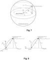
- the center point C arc B of the arc is found first by using the following method illustrated in Fig. 9 .
- the unit vector rotated by ⁇ 2 is n ' ⁇ y lookahead ′ B dist 2 D p lookahead ′ B x lookahead ′ B dist 2 D p lookahead ′ B .
- C arc B x lookahead ′ B 2 ⁇ ⁇ ⁇ b ⁇ y lookahead ′ B dist 2 D p lookahead ′ B , y lookahead ′ B 2 + ⁇ ⁇ b ⁇ y lookahead ′ B dist 2 D p lookahead ′ B .
- the commands computed previously are refined to ensure smooth operation over a greater velocity range.
- This refinement operation is in two steps: first adjustment of the velocity based on the curvature of the arc from the drone to the lookahead point, and secondly an acceleration-based smoothing.
- the velocity command is reduced on high curvature of the arc going from the drone to the lookahead point to avoid overshooting.
- This technic already exists in the literature but only with arc in 2D in the xy plane.
- the arc taken in consideration for this velocity regulation is not the previously calculated arc of center C arc and radius r arc in the xy plane, but another arc in 3D to address thigh curve motion vertically as well.
- the arc from the drone to the lookahead point must be tangent to the drone direction of motion in 3D.
- the angle ⁇ is used to define a rotated frame R C ( Fig. 10 ) around the y-axis and transform the chosen lookahead point in this frame (as shown in Fig. 11 ).
- v' x be the refined horizontal x-axis velocity norm based on curvature
- v' y be the refined horizontal y-axis velocity norm based on curvature
- v' z the refined vertical velocity norm based on curvature.
- T r itself is a dynamic value that adapts to the desired velocity of the drone v desired .
- f is the scaling factor to convert velocity to a radius value and Tr min and Tr max are respectively the minimum value and maximum value for Tc.
- T r ⁇ v desired ⁇ f Tr min ⁇ v desired ⁇ f ⁇ Tr max Tr min v desired ⁇ f ⁇ Tr min Tr max v desired ⁇ f > Tr max
- the last element of the velocity regulation is an acceleration and jerk based smoother to adapt the velocity.
- Multicopter are subject to higher accelerations than ground robots and the controller should be able to smooth rough velocity commands (generated from highly curved path for example).
- the smoothing process works in discrete time.
- the notation q[t] is used to distinguish discrete time quantity.
- e smoothed smooth e t , e t ⁇ 1 , a t ⁇ 1 , dt , D , j limit , where e t is the velocity input to be smoothed, e[t - 1] is the previous velocity input, a [ t - 1] the previous acceleration, dt the time increment between t - 1 and t, D the velocity input deadband within which the smoothing process will not apply, j imit the jerk limits.
- the function smooth ( e [ t ], e [ t - 1], a [ t - 1], dt, D,j limit ) works by first having the maximum and minimum value for e[t], respectively e max and e min defined.
- e smoothed ⁇ e t e min ⁇ e t ⁇ e max e min e t ⁇ e min e max e t > e max .
- U smoothed is the velocity command fed to the drone controller.
- Most multicopters will provide the capability for velocity command while handling the low-level aspect of the control (individual thrust generation). This approach is a trade-off between full-body control and position control input.
- Full-body would require a dynamic model of the drone, a long tuning process and a multicopter manufacturer that would allow thrust input commands.
- Position control input would require virtually no tuning but would not be able to reach high performances, especially with highly curved paths.
- Velocity command input allows to reach high performance with minimal tuning by taking advantage of the path controller heuristics and regulation capabilities while also relying on the drone manufacturer fine tuning of the low-level thrust control.
- Certain aspects of the present invention include process steps or operations and instructions described herein in an algorithmic and/or algorithmic-like form. It should be noted that the process steps and/or operations and instructions of the present invention can be embodied in software, firmware, and/or hardware, and when embodied in software, can be downloaded to reside on and be operated from different platforms used by real-time network operating systems.
Landscapes
- Engineering & Computer Science (AREA)
- Aviation & Aerospace Engineering (AREA)
- Radar, Positioning & Navigation (AREA)
- Remote Sensing (AREA)
- Physics & Mathematics (AREA)
- General Physics & Mathematics (AREA)
- Automation & Control Theory (AREA)
- Control Of Position, Course, Altitude, Or Attitude Of Moving Bodies (AREA)
Priority Applications (1)
| Application Number | Priority Date | Filing Date | Title |
|---|---|---|---|
| EP23217553.9A EP4575700A1 (de) | 2023-12-18 | 2023-12-18 | Verfahren, system und computerprogramme zur steuerung von multikopterdrohnen |
Applications Claiming Priority (1)
| Application Number | Priority Date | Filing Date | Title |
|---|---|---|---|
| EP23217553.9A EP4575700A1 (de) | 2023-12-18 | 2023-12-18 | Verfahren, system und computerprogramme zur steuerung von multikopterdrohnen |
Publications (1)
| Publication Number | Publication Date |
|---|---|
| EP4575700A1 true EP4575700A1 (de) | 2025-06-25 |
Family
ID=89223753
Family Applications (1)
| Application Number | Title | Priority Date | Filing Date |
|---|---|---|---|
| EP23217553.9A Pending EP4575700A1 (de) | 2023-12-18 | 2023-12-18 | Verfahren, system und computerprogramme zur steuerung von multikopterdrohnen |
Country Status (1)
| Country | Link |
|---|---|
| EP (1) | EP4575700A1 (de) |
Citations (2)
| Publication number | Priority date | Publication date | Assignee | Title |
|---|---|---|---|---|
| US20100324812A1 (en) * | 2009-05-15 | 2010-12-23 | Thales | Method of short-term rejoining of a flight plan by radar guidance of an aircraft |
| US20190064794A1 (en) * | 2015-12-09 | 2019-02-28 | SZ DJI Technology Co., Ltd. | Systems and methods for uav flight control |
-
2023
- 2023-12-18 EP EP23217553.9A patent/EP4575700A1/de active Pending
Patent Citations (2)
| Publication number | Priority date | Publication date | Assignee | Title |
|---|---|---|---|---|
| US20100324812A1 (en) * | 2009-05-15 | 2010-12-23 | Thales | Method of short-term rejoining of a flight plan by radar guidance of an aircraft |
| US20190064794A1 (en) * | 2015-12-09 | 2019-02-28 | SZ DJI Technology Co., Ltd. | Systems and methods for uav flight control |
Non-Patent Citations (1)
| Title |
|---|
| DE MEL DANIEL H S ET AL: "Vision-based object path following on a quadcopter for GPS-denied environments", 2017 INTERNATIONAL CONFERENCE ON UNMANNED AIRCRAFT SYSTEMS (ICUAS), IEEE, 13 June 2017 (2017-06-13), pages 456 - 461, XP033131908, DOI: 10.1109/ICUAS.2017.7991500 * |
Similar Documents
| Publication | Publication Date | Title |
|---|---|---|
| EP1365301B1 (de) | System und Verfahren zum Manövrieren eines beweglichen Objektes | |
| US11485521B2 (en) | Spacecraft and control device | |
| CA3094757A1 (en) | Aircraft control systems and methods using sliding mode control and feedback linearization | |
| Oliveira et al. | Moving path following for autonomous robotic vehicles | |
| Koo et al. | Hierarchical hybrid system design on Berkeley UAV | |
| CN118051074B (zh) | 一种速度控制模式下的图像伺服软管式自动空中加油对接控制方法 | |
| Bacon | Quaternion-based control architecture for determining controllability/maneuverability limits | |
| Fossen | An amplitude-phase representation of the North-East-Down kinematic differential equations | |
| EP4575700A1 (de) | Verfahren, system und computerprogramme zur steuerung von multikopterdrohnen | |
| Wan et al. | Model predictive neural control of a high-fidelity helicopter model | |
| Schoerling et al. | Experimental test of a robust formation controller for marine unmanned surface vessels | |
| Zhang et al. | Image-based fixed-time visual servoing control for UAV landing on a moving platform with visibility constraints: C. Zhang et al. | |
| Mochurad et al. | An autopilot-based method for unmanned aerial vehicles trajectories control and adjustment | |
| Cabecinhas et al. | Path-following control for coordinated turn aircraft maneuvers | |
| Jensen | Waypoint-following guidance based on feasibility algorithms | |
| Andersen et al. | Path-following in three dimensions using quaternions for a fixed-wing UAV | |
| CN118295397A (zh) | 无人船路径规划与跟踪方法及系统 | |
| US20260029804A1 (en) | System and method for flexible relational maneuvering of leader-follower unmanned aerial vehicles | |
| Häusler et al. | Multiple marine vehicle deconflicted path planning with currents and communication constraints | |
| Yang et al. | Dubins path generation and tracking in 3D for UAVs | |
| Giulietti et al. | Optimal autonomous quadrotor navigation in an obstructed space | |
| Bibuli | Virtual-target based path-following in the 3D underwater environment | |
| Akimov et al. | Aircraft drift away from limiting surfaces along programmed trajectories | |
| Yao | A Singularity-Free Guiding Vector Field for Robot Navigation | |
| Radmanesh et al. | On the effect of different splines on way-point navigation of quad-copters |
Legal Events
| Date | Code | Title | Description |
|---|---|---|---|
| PUAI | Public reference made under article 153(3) epc to a published international application that has entered the european phase |
Free format text: ORIGINAL CODE: 0009012 |
|
| STAA | Information on the status of an ep patent application or granted ep patent |
Free format text: STATUS: THE APPLICATION HAS BEEN PUBLISHED |
|
| AK | Designated contracting states |
Kind code of ref document: A1 Designated state(s): AL AT BE BG CH CY CZ DE DK EE ES FI FR GB GR HR HU IE IS IT LI LT LU LV MC ME MK MT NL NO PL PT RO RS SE SI SK SM TR |
|
| STAA | Information on the status of an ep patent application or granted ep patent |
Free format text: STATUS: THE APPLICATION IS DEEMED TO BE WITHDRAWN |