EP4575648A1 - Electronic apparatus - Google Patents
Electronic apparatus Download PDFInfo
- Publication number
- EP4575648A1 EP4575648A1 EP24220462.6A EP24220462A EP4575648A1 EP 4575648 A1 EP4575648 A1 EP 4575648A1 EP 24220462 A EP24220462 A EP 24220462A EP 4575648 A1 EP4575648 A1 EP 4575648A1
- Authority
- EP
- European Patent Office
- Prior art keywords
- accumulated
- rotations
- operation time
- motor units
- motor
- Prior art date
- Legal status (The legal status is an assumption and is not a legal conclusion. Google has not performed a legal analysis and makes no representation as to the accuracy of the status listed.)
- Pending
Links
Images

Classifications
-
- H—ELECTRICITY
- H04—ELECTRIC COMMUNICATION TECHNIQUE
- H04N—PICTORIAL COMMUNICATION, e.g. TELEVISION
- H04N1/00—Scanning, transmission or reproduction of documents or the like, e.g. facsimile transmission; Details thereof
- H04N1/00002—Diagnosis, testing or measuring; Detecting, analysing or monitoring not otherwise provided for
- H04N1/00026—Methods therefor
- H04N1/00037—Detecting, i.e. determining the occurrence of a predetermined state
-
- G—PHYSICS
- G03—PHOTOGRAPHY; CINEMATOGRAPHY; ANALOGOUS TECHNIQUES USING WAVES OTHER THAN OPTICAL WAVES; ELECTROGRAPHY; HOLOGRAPHY
- G03G—ELECTROGRAPHY; ELECTROPHOTOGRAPHY; MAGNETOGRAPHY
- G03G21/00—Arrangements not provided for by groups G03G13/00 - G03G19/00, e.g. cleaning, elimination of residual charge
- G03G21/16—Mechanical means for facilitating the maintenance of the apparatus, e.g. modular arrangements
- G03G21/1642—Mechanical means for facilitating the maintenance of the apparatus, e.g. modular arrangements for connecting the different parts of the apparatus
- G03G21/1647—Mechanical connection means
-
- G—PHYSICS
- G03—PHOTOGRAPHY; CINEMATOGRAPHY; ANALOGOUS TECHNIQUES USING WAVES OTHER THAN OPTICAL WAVES; ELECTROGRAPHY; HOLOGRAPHY
- G03G—ELECTROGRAPHY; ELECTROPHOTOGRAPHY; MAGNETOGRAPHY
- G03G15/00—Apparatus for electrographic processes using a charge pattern
- G03G15/55—Self-diagnostics; Malfunction or lifetime display
-
- G—PHYSICS
- G03—PHOTOGRAPHY; CINEMATOGRAPHY; ANALOGOUS TECHNIQUES USING WAVES OTHER THAN OPTICAL WAVES; ELECTROGRAPHY; HOLOGRAPHY
- G03G—ELECTROGRAPHY; ELECTROPHOTOGRAPHY; MAGNETOGRAPHY
- G03G15/00—Apparatus for electrographic processes using a charge pattern
- G03G15/65—Apparatus which relate to the handling of copy material
- G03G15/6502—Supplying of sheet copy material; Cassettes therefor
- G03G15/6511—Feeding devices for picking up or separation of copy sheets
-
- H—ELECTRICITY
- H04—ELECTRIC COMMUNICATION TECHNIQUE
- H04N—PICTORIAL COMMUNICATION, e.g. TELEVISION
- H04N1/00—Scanning, transmission or reproduction of documents or the like, e.g. facsimile transmission; Details thereof
- H04N1/0035—User-machine interface; Control console
- H04N1/00405—Output means
- H04N1/00408—Display of information to the user, e.g. menus
- H04N1/00411—Display of information to the user, e.g. menus the display also being used for user input, e.g. touch screen
-
- G—PHYSICS
- G03—PHOTOGRAPHY; CINEMATOGRAPHY; ANALOGOUS TECHNIQUES USING WAVES OTHER THAN OPTICAL WAVES; ELECTROGRAPHY; HOLOGRAPHY
- G03G—ELECTROGRAPHY; ELECTROPHOTOGRAPHY; MAGNETOGRAPHY
- G03G15/00—Apparatus for electrographic processes using a charge pattern
- G03G15/50—Machine control of apparatus for electrographic processes using a charge pattern, e.g. regulating differents parts of the machine, multimode copiers, microprocessor control
- G03G15/5004—Power supply control, e.g. power-saving mode, automatic power turn-off
-
- G—PHYSICS
- G03—PHOTOGRAPHY; CINEMATOGRAPHY; ANALOGOUS TECHNIQUES USING WAVES OTHER THAN OPTICAL WAVES; ELECTROGRAPHY; HOLOGRAPHY
- G03G—ELECTROGRAPHY; ELECTROPHOTOGRAPHY; MAGNETOGRAPHY
- G03G15/00—Apparatus for electrographic processes using a charge pattern
- G03G15/50—Machine control of apparatus for electrographic processes using a charge pattern, e.g. regulating differents parts of the machine, multimode copiers, microprocessor control
- G03G15/5016—User-machine interface; Display panels; Control console
-
- G—PHYSICS
- G03—PHOTOGRAPHY; CINEMATOGRAPHY; ANALOGOUS TECHNIQUES USING WAVES OTHER THAN OPTICAL WAVES; ELECTROGRAPHY; HOLOGRAPHY
- G03G—ELECTROGRAPHY; ELECTROPHOTOGRAPHY; MAGNETOGRAPHY
- G03G15/00—Apparatus for electrographic processes using a charge pattern
- G03G15/50—Machine control of apparatus for electrographic processes using a charge pattern, e.g. regulating differents parts of the machine, multimode copiers, microprocessor control
- G03G15/5016—User-machine interface; Display panels; Control console
- G03G15/502—User-machine interface; Display panels; Control console relating to the structure of the control menu, e.g. pop-up menus, help screens
-
- G—PHYSICS
- G03—PHOTOGRAPHY; CINEMATOGRAPHY; ANALOGOUS TECHNIQUES USING WAVES OTHER THAN OPTICAL WAVES; ELECTROGRAPHY; HOLOGRAPHY
- G03G—ELECTROGRAPHY; ELECTROPHOTOGRAPHY; MAGNETOGRAPHY
- G03G15/00—Apparatus for electrographic processes using a charge pattern
- G03G15/55—Self-diagnostics; Malfunction or lifetime display
- G03G15/553—Monitoring or warning means for exhaustion or lifetime end of consumables, e.g. indication of insufficient copy sheet quantity for a job
-
- G—PHYSICS
- G03—PHOTOGRAPHY; CINEMATOGRAPHY; ANALOGOUS TECHNIQUES USING WAVES OTHER THAN OPTICAL WAVES; ELECTROGRAPHY; HOLOGRAPHY
- G03G—ELECTROGRAPHY; ELECTROPHOTOGRAPHY; MAGNETOGRAPHY
- G03G15/00—Apparatus for electrographic processes using a charge pattern
- G03G15/75—Details relating to xerographic drum, band or plate, e.g. replacing, testing
- G03G15/757—Drive mechanisms for photosensitive medium, e.g. gears
-
- G—PHYSICS
- G03—PHOTOGRAPHY; CINEMATOGRAPHY; ANALOGOUS TECHNIQUES USING WAVES OTHER THAN OPTICAL WAVES; ELECTROGRAPHY; HOLOGRAPHY
- G03G—ELECTROGRAPHY; ELECTROPHOTOGRAPHY; MAGNETOGRAPHY
- G03G21/00—Arrangements not provided for by groups G03G13/00 - G03G19/00, e.g. cleaning, elimination of residual charge
- G03G21/16—Mechanical means for facilitating the maintenance of the apparatus, e.g. modular arrangements
- G03G21/18—Mechanical means for facilitating the maintenance of the apparatus, e.g. modular arrangements using a processing cartridge, whereby the process cartridge comprises at least two image processing means in a single unit
- G03G21/1839—Means for handling the process cartridge in the apparatus body
- G03G21/1857—Means for handling the process cartridge in the apparatus body for transmitting mechanical drive power to the process cartridge, drive mechanisms, gears, couplings, braking mechanisms
-
- G—PHYSICS
- G03—PHOTOGRAPHY; CINEMATOGRAPHY; ANALOGOUS TECHNIQUES USING WAVES OTHER THAN OPTICAL WAVES; ELECTROGRAPHY; HOLOGRAPHY
- G03G—ELECTROGRAPHY; ELECTROPHOTOGRAPHY; MAGNETOGRAPHY
- G03G2221/00—Processes not provided for by group G03G2215/00, e.g. cleaning or residual charge elimination
- G03G2221/16—Mechanical means for facilitating the maintenance of the apparatus, e.g. modular arrangements and complete machine concepts
- G03G2221/1651—Mechanical means for facilitating the maintenance of the apparatus, e.g. modular arrangements and complete machine concepts for connecting the different parts
- G03G2221/1657—Mechanical means for facilitating the maintenance of the apparatus, e.g. modular arrangements and complete machine concepts for connecting the different parts transmitting mechanical drive power
-
- H—ELECTRICITY
- H04—ELECTRIC COMMUNICATION TECHNIQUE
- H04N—PICTORIAL COMMUNICATION, e.g. TELEVISION
- H04N2201/00—Indexing scheme relating to scanning, transmission or reproduction of documents or the like, and to details thereof
- H04N2201/0077—Types of the still picture apparatus
- H04N2201/0094—Multifunctional device, i.e. a device capable of all of reading, reproducing, copying, facsimile transception, file transception
Definitions
- the present invention relates to an electronic apparatus.
- An image forming apparatus includes a built-in sheet transportation device, and determines a lifetime of DC motor or the like in the sheet transportation device on the basis of a rotation speed of the DC motor.
- Another image forming apparatus includes plural sheet feeding cassettes, counts the number of times of sheet feeding by a roller in each sheet feeding cassette, and performs indication to prompt exchange between a roller feeding sheets a large number of times and a roller feeding sheets a small number of times in plural sheet feeding cassettes.
- An electronic apparatus includes plural motor units exchangeable with each other.
- Each of the plural motor units includes a counter configured to count an accumulated number of rotations or accumulated operation time and display any of the accumulated number of rotations, the accumulated operation time and a remaining lifetime based on the accumulated number of rotations or the accumulated operation time.
- Fig. 1 shows a block diagram that indicates a configuration of an electronic apparatus according to an embodiment of the present invention.
- the electronic apparatus includes plural motor units 1, an operation panel 21, and a controller 22.
- the motor units 1 are driving force sources of sheet transportation or the like in an internal device 11.
- this electronic apparatus is an image forming apparatus such as a multi function peripheral, and includes as the internal device 11 a printing device, an image scanning device and/or the like.
- the plural motor units 1 are exchangeable with each other, and each of the motor units 1 is a motor assy (assembly) that includes a motor 1a, a counter 1b, and a connector 1c.
- the counter 1b may be a mechanical counter or an electronic counter. If the counter 1b is an electronic counter, the counter 1b detects the number of rotations using a rotary encoder or the like, counts an accumulated number of rotations or an accumulated operation time using an electronic circuit and stores it into a nonvolatile memory, and displays the accumulated number of rotations, the accumulated operation time, the remaining lifetime and/or the like using a small display panel or an indicator.
- a harness is detachable and attachable.
- the harness makes electric connection between the controller 22 and the motor unit 1 and between the controller 22 and a power supply (not shown).
- the operation panel 21 is arranged in a front side of the image forming apparatus, and includes a display device 21a such as a liquid crystal display and an input device 21b such as a touch panel and/or a hard key.
- the display device 21a displays sorts of information to a user.
- the input device 21b detects a user operation inputted by a user to the hard key or the soft key.
- the controller 22 is a computer or the like, controls the internal device 11 and thereby performs a job (such as printing, scanning, copying or the like).
- the controller 22 may read count values from the respective counters 1d in the plural motor units 1 and may display the count values on the display device 21a.
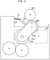
- Fig. 2 shows a side-view diagram that indicates an example of a motor unit 1 shown in Fig. 1 .
- the motor unit 1 further includes a housing 1d to which the motor 1a and the like are fixed, a gear 31b connected to a rotation axis 31a of the motor 1a, a gear 32b that is connected to the gear 31b and rotates around a rotation axis 32a as a center.
- the gear 32b is connected to an external gear 101 and enabled to be apart from the external gear 101 when the plural motor units 1 are exchanged.
- demounting and mounting of the motor unit 1 can be easily performed.
- the motor unit 1 is fixed with a few screws, and therefore a user can easily perform demounting and mounting of the motor unit 1.
- a swinging member 33 is installed such that the swinging member 33 is enabled to swing around the rotation axis 31a as a center, and the rotation axis 32a is installed on the swinging member 33. Further, a spring 34 adds force to the swinging member 33 such that the gear 32b makes contact to the external gear 101.
- the swinging member 33 When exchanging plural motor units 1, the swinging member 33 is caused to swing against a restoring force of the spring 34 by a manual operation or an electromotive operation, and thereby the gear 32b becomes apart from the external gear 101.
- an actuator is installed for the electromotive operation, and the controller 22 displays a soft key to demount the plural motor units 1 on the display device 21a with the aforementioned count values, and if pressing down of the soft key is detected by the input device 21b, causes the actuator to act and thereby causes the swinging member 33 to swing. During this action, power supply to the motor units 1 is cut off.
- the controller 22 controls the internal device 11 (the motor 1a) corresponding to a job to be performed and thereby performs the job.
- the counter 1b in the motor unit 1 counts and renews the accumulated number of rotations and/or the accumulated operation time of the motor 1a correspondingly to operation of the motor 1a, and displays the accumulated number of rotations, the accumulated operation time, the remaining lifetime and/or the like.
- a different internal device 11 is used in accordance with a type of a job to be performed, and operation frequencies of the motor units 1 in the internal device 11 are different from each other. Therefore, the count values (such as the accumulated number of rotations, the accumulated operation time or the remaining lifetime) displayed on the counters 1b in the plural motor units 1 are different from each other.
- a user visually understands the count values such as the accumulated number of rotations, the accumulated operation time or the remaining lifetime displayed on the counters 1b in the plural motor units 1, and exchanges a motor unit 1 of a large count value and a motor unit 1 of a small count value among the plural motor units 1. Consequently, the accumulated number of rotations, the accumulated operation time or the remaining lifetime gets close to evenness among the plural motor units 1.
- the electronic apparatus includes plural motor units 1 exchangeable with each other. Further, each of the plural motor units 1 includes the counter 1b that counts an accumulated number of rotations or accumulated operation time and displays any of the accumulated number of rotations, the accumulated operation time and a remaining lifetime based on the accumulated number of rotations or the accumulated operation time.
- the motor unit 1 may be exchangeable with a motor unit in another electronic apparatus of a different type.
- the motor unit 1 may be exchanged with a brand-new motor unit 1.
Landscapes
- Engineering & Computer Science (AREA)
- General Physics & Mathematics (AREA)
- Physics & Mathematics (AREA)
- Signal Processing (AREA)
- Multimedia (AREA)
- Health & Medical Sciences (AREA)
- Human Computer Interaction (AREA)
- Biomedical Technology (AREA)
- General Health & Medical Sciences (AREA)
- Control Of Electric Motors In General (AREA)
- Control Or Security For Electrophotography (AREA)
- Facsimiles In General (AREA)
- Accessory Devices And Overall Control Thereof (AREA)
Abstract
An electronic apparatus includes plural motor units exchangeable with each other. Each of the plural motor units includes a counter that counts an accumulated number of rotations or accumulated operation time and displays any of the accumulated number of rotations, the accumulated operation time and a remaining lifetime based on the accumulated number of rotations or the accumulated operation time.
Description
- The present invention relates to an electronic apparatus.
- An image forming apparatus includes a built-in sheet transportation device, and determines a lifetime of DC motor or the like in the sheet transportation device on the basis of a rotation speed of the DC motor.
- Another image forming apparatus includes plural sheet feeding cassettes, counts the number of times of sheet feeding by a roller in each sheet feeding cassette, and performs indication to prompt exchange between a roller feeding sheets a large number of times and a roller feeding sheets a small number of times in plural sheet feeding cassettes.
- However, in the aforementioned image forming apparatus, a count value is not maintained by the roller itself or the sheet feeding cassette itself, and consequently, after plural rollers are demounted, these rollers may be mounted to wrong cassettes in error, and it is bothersome because the counting of sheet feeding by the roller must be continued through the exchange.
- An electronic apparatus according to the present invention includes plural motor units exchangeable with each other. Each of the plural motor units includes a counter configured to count an accumulated number of rotations or accumulated operation time and display any of the accumulated number of rotations, the accumulated operation time and a remaining lifetime based on the accumulated number of rotations or the accumulated operation time.
- These and other objects, features and advantages of the present invention will become more apparent upon reading of the following detailed description along with the accompanied drawings.
-
-
Fig. 1 shows a block diagram that indicates a configuration of an electronic apparatus according to an embodiment of the present invention; and -
Fig. 2 shows a side-view diagram that indicates an example of amotor unit 1 shown inFig. 1 . - Hereinafter, an embodiment according to an aspect of the present invention will be explained with reference to drawings.
-
Fig. 1 shows a block diagram that indicates a configuration of an electronic apparatus according to an embodiment of the present invention. The electronic apparatus includesplural motor units 1, anoperation panel 21, and acontroller 22. Themotor units 1 are driving force sources of sheet transportation or the like in aninternal device 11. For example, this electronic apparatus is an image forming apparatus such as a multi function peripheral, and includes as the internal device 11 a printing device, an image scanning device and/or the like. - The
plural motor units 1 are exchangeable with each other, and each of themotor units 1 is a motor assy (assembly) that includes amotor 1a, acounter 1b, and aconnector 1c. - The
counter 1b counts an accumulated number of rotations or accumulated operation time of themotor 1a and displays any of (a) the accumulated number of rotations, (b) the accumulated operation time and (c) a remaining lifetime based on the accumulated number of rotations or the accumulated operation time. Therefore, even when themotor unit 1 is demounted, a user can see (a) the accumulated number of rotations, (b) the accumulated operation time, (c) the remaining lifetime and/or the like of thismotor unit 1. - For example, the
counter 1b may be a mechanical counter or an electronic counter. If thecounter 1b is an electronic counter, thecounter 1b detects the number of rotations using a rotary encoder or the like, counts an accumulated number of rotations or an accumulated operation time using an electronic circuit and stores it into a nonvolatile memory, and displays the accumulated number of rotations, the accumulated operation time, the remaining lifetime and/or the like using a small display panel or an indicator. - To the
connector 1c, a harness is detachable and attachable. The harness makes electric connection between thecontroller 22 and themotor unit 1 and between thecontroller 22 and a power supply (not shown). - The
operation panel 21 is arranged in a front side of the image forming apparatus, and includes adisplay device 21a such as a liquid crystal display and aninput device 21b such as a touch panel and/or a hard key. Thedisplay device 21a displays sorts of information to a user. Theinput device 21b detects a user operation inputted by a user to the hard key or the soft key. - The
controller 22 is a computer or the like, controls theinternal device 11 and thereby performs a job (such as printing, scanning, copying or the like). Thecontroller 22 may read count values from therespective counters 1d in theplural motor units 1 and may display the count values on thedisplay device 21a. -
Fig. 2 shows a side-view diagram that indicates an example of amotor unit 1 shown inFig. 1 . As shown inFig. 2 , for example, themotor unit 1 further includes ahousing 1d to which themotor 1a and the like are fixed, a gear 31b connected to a rotation axis 31a of themotor 1a, agear 32b that is connected to the gear 31b and rotates around arotation axis 32a as a center. - The
gear 32b is connected to anexternal gear 101 and enabled to be apart from theexternal gear 101 when theplural motor units 1 are exchanged. When thegear 32b is apart from theexternal gear 101, demounting and mounting of themotor unit 1 can be easily performed. For example, themotor unit 1 is fixed with a few screws, and therefore a user can easily perform demounting and mounting of themotor unit 1. - As shown in
Fig. 2 , for example, a swingingmember 33 is installed such that the swingingmember 33 is enabled to swing around the rotation axis 31a as a center, and therotation axis 32a is installed on theswinging member 33. Further, aspring 34 adds force to the swingingmember 33 such that thegear 32b makes contact to theexternal gear 101. - When exchanging
plural motor units 1, the swingingmember 33 is caused to swing against a restoring force of thespring 34 by a manual operation or an electromotive operation, and thereby thegear 32b becomes apart from theexternal gear 101. For example, if the swingingmember 33 is caused to swing by an electromotive operation, an actuator is installed for the electromotive operation, and thecontroller 22 displays a soft key to demount theplural motor units 1 on thedisplay device 21a with the aforementioned count values, and if pressing down of the soft key is detected by theinput device 21b, causes the actuator to act and thereby causes the swingingmember 33 to swing. During this action, power supply to themotor units 1 is cut off. - The following part explains the aforementioned electronic apparatus.
- The
controller 22 controls the internal device 11 (themotor 1a) corresponding to a job to be performed and thereby performs the job. At that time, thecounter 1b in themotor unit 1 counts and renews the accumulated number of rotations and/or the accumulated operation time of themotor 1a correspondingly to operation of themotor 1a, and displays the accumulated number of rotations, the accumulated operation time, the remaining lifetime and/or the like. - A different
internal device 11 is used in accordance with a type of a job to be performed, and operation frequencies of themotor units 1 in theinternal device 11 are different from each other. Therefore, the count values (such as the accumulated number of rotations, the accumulated operation time or the remaining lifetime) displayed on thecounters 1b in theplural motor units 1 are different from each other. - A user visually understands the count values such as the accumulated number of rotations, the accumulated operation time or the remaining lifetime displayed on the
counters 1b in theplural motor units 1, and exchanges amotor unit 1 of a large count value and amotor unit 1 of a small count value among theplural motor units 1. Consequently, the accumulated number of rotations, the accumulated operation time or the remaining lifetime gets close to evenness among theplural motor units 1. - As mentioned, in the aforementioned embodiment, the electronic apparatus includes
plural motor units 1 exchangeable with each other. Further, each of theplural motor units 1 includes thecounter 1b that counts an accumulated number of rotations or accumulated operation time and displays any of the accumulated number of rotations, the accumulated operation time and a remaining lifetime based on the accumulated number of rotations or the accumulated operation time. - Consequently, a user can easily understand a lifetime of each of the
motor units 1 and can easily exchange themotor units 1 with each other. - It should be understood that various changes and modifications to the embodiments described herein will be apparent to those skilled in the art. Such changes and modifications may be made without departing from the spirit and scope of the present subject matter and without diminishing its intended advantages. It is therefore intended that such changes and modifications be covered by the appended claims.
- For example, in the aforementioned embodiment, the
motor unit 1 may be exchangeable with a motor unit in another electronic apparatus of a different type. - Further, in the aforementioned embodiment, the
motor unit 1 may be exchanged with a brand-new motor unit 1.
Claims (3)
- An electronic apparatus, comprisingplural motor units exchangeable with each other;wherein each of the plural motor units comprises a counter configured to count an accumulated number of rotations or accumulated operation time and display any of the accumulated number of rotations, the accumulated operation time and a remaining lifetime based on the accumulated number of rotations or the accumulated operation time.
- The electronic apparatus according to claim 1, wherein each of the motor units comprises a housing, a motor, and a gear configured to connect with an external gear; and
the gear is enabled to be apart from the external gear when the plural motor units are exchanged. - The electronic apparatus according to claim 1, further comprising:a display device; anda controller;wherein the controller reads count values of the counters from the plural motor units and displays the count values on the display device.
Applications Claiming Priority (1)
| Application Number | Priority Date | Filing Date | Title |
|---|---|---|---|
| JP2023215456A JP2025099081A (en) | 2023-12-21 | 2023-12-21 | Electronic apparatus |
Publications (1)
| Publication Number | Publication Date |
|---|---|
| EP4575648A1 true EP4575648A1 (en) | 2025-06-25 |
Family
ID=93926711
Family Applications (1)
| Application Number | Title | Priority Date | Filing Date |
|---|---|---|---|
| EP24220462.6A Pending EP4575648A1 (en) | 2023-12-21 | 2024-12-17 | Electronic apparatus |
Country Status (4)
| Country | Link |
|---|---|
| US (1) | US20250211686A1 (en) |
| EP (1) | EP4575648A1 (en) |
| JP (1) | JP2025099081A (en) |
| CN (1) | CN120195942A (en) |
Citations (5)
| Publication number | Priority date | Publication date | Assignee | Title |
|---|---|---|---|---|
| JP2007032712A (en) * | 2005-07-27 | 2007-02-08 | Nachi Fujikoshi Corp | Motor bearing deterioration monitoring device and control system |
| US20070122165A1 (en) * | 2005-11-30 | 2007-05-31 | Brother Kogyo Kabushiki Kaisha | Image forming apparatus and developer cartridge |
| US20140321866A1 (en) * | 2013-04-27 | 2014-10-30 | Kyocera Document Solutions Inc. | Electronic apparatus and image forming apparatus |
| US10649386B2 (en) * | 2016-09-29 | 2020-05-12 | Canon Kabushiki Kaisha | Driving device and image forming apparatus |
| US10719045B2 (en) * | 2018-03-13 | 2020-07-21 | Kabushiki Kaisha Toshiba | Image forming apparatus and control method of image forming apparatus |
Family Cites Families (3)
| Publication number | Priority date | Publication date | Assignee | Title |
|---|---|---|---|---|
| US7273007B2 (en) * | 2004-09-27 | 2007-09-25 | Printing Research, Inc. | Portable printer coater |
| JP4928170B2 (en) * | 2006-06-12 | 2012-05-09 | キヤノン株式会社 | Image forming apparatus |
| US20230251354A1 (en) * | 2022-02-10 | 2023-08-10 | Santec Corporation | Compact beam steering mechanism and system |
-
2023
- 2023-12-21 JP JP2023215456A patent/JP2025099081A/en active Pending
-
2024
- 2024-12-11 CN CN202411817085.2A patent/CN120195942A/en active Pending
- 2024-12-17 EP EP24220462.6A patent/EP4575648A1/en active Pending
- 2024-12-17 US US18/984,883 patent/US20250211686A1/en active Pending
Patent Citations (5)
| Publication number | Priority date | Publication date | Assignee | Title |
|---|---|---|---|---|
| JP2007032712A (en) * | 2005-07-27 | 2007-02-08 | Nachi Fujikoshi Corp | Motor bearing deterioration monitoring device and control system |
| US20070122165A1 (en) * | 2005-11-30 | 2007-05-31 | Brother Kogyo Kabushiki Kaisha | Image forming apparatus and developer cartridge |
| US20140321866A1 (en) * | 2013-04-27 | 2014-10-30 | Kyocera Document Solutions Inc. | Electronic apparatus and image forming apparatus |
| US10649386B2 (en) * | 2016-09-29 | 2020-05-12 | Canon Kabushiki Kaisha | Driving device and image forming apparatus |
| US10719045B2 (en) * | 2018-03-13 | 2020-07-21 | Kabushiki Kaisha Toshiba | Image forming apparatus and control method of image forming apparatus |
Also Published As
| Publication number | Publication date |
|---|---|
| JP2025099081A (en) | 2025-07-03 |
| US20250211686A1 (en) | 2025-06-26 |
| CN120195942A (en) | 2025-06-24 |
Similar Documents
| Publication | Publication Date | Title |
|---|---|---|
| CN114683219B (en) | Electric working machine | |
| EP1965272B1 (en) | Cartridge comprising an engagement gear and a rotation body | |
| JP4492260B2 (en) | Printing control apparatus and effective utilization method and program for consumables mounted on the apparatus | |
| US20180212540A1 (en) | Image forming apparatus, motor controller and method for diagnosing fault thereof | |
| EP3167338B1 (en) | Developer cartridge | |
| US20250211686A1 (en) | Electronic apparatus | |
| JP4492715B2 (en) | Fan control device and image forming apparatus | |
| EP3680109B1 (en) | Printer | |
| EP3643505B1 (en) | Thermal printer and portable terminal | |
| CN111610829A (en) | Hard disk fixing structure and image forming apparatus having the same | |
| EP3437888A1 (en) | Tape cassette | |
| JP2017067885A (en) | Developing cartridge | |
| JP2022110650A (en) | Printing device | |
| JP2008053815A (en) | Image forming apparatus, and control method of image forming apparatus | |
| CN109318604B (en) | Unit assembling structure and printing apparatus | |
| JP2019031023A (en) | Image formation apparatus, control method, and program | |
| JP2004289553A (en) | Rotary drive | |
| TW201400315A (en) | Printer enclosure | |
| JP4169010B2 (en) | Information processing system and information display method in information processing system | |
| JP6696471B2 (en) | Electronics | |
| US8934105B2 (en) | Image forming apparatus and control method with error detecting and line switching function | |
| JP2000304339A (en) | Electrical equipment | |
| EP4703847A1 (en) | Electronic apparatus | |
| JP4087756B2 (en) | Image forming apparatus, information processing method thereof, and information processing program | |
| JP2019174626A (en) | Developing cartridge |
Legal Events
| Date | Code | Title | Description |
|---|---|---|---|
| PUAI | Public reference made under article 153(3) epc to a published international application that has entered the european phase |
Free format text: ORIGINAL CODE: 0009012 |
|
| STAA | Information on the status of an ep patent application or granted ep patent |
Free format text: STATUS: THE APPLICATION HAS BEEN PUBLISHED |
|
| AK | Designated contracting states |
Kind code of ref document: A1 Designated state(s): AL AT BE BG CH CY CZ DE DK EE ES FI FR GB GR HR HU IE IS IT LI LT LU LV MC ME MK MT NL NO PL PT RO RS SE SI SK SM TR |
|
| STAA | Information on the status of an ep patent application or granted ep patent |
Free format text: STATUS: REQUEST FOR EXAMINATION WAS MADE |
|
| 17P | Request for examination filed |
Effective date: 20251211 |