EP4575554A1 - Rekursive deterministische maximalwahrscheinlichkeitsschätzung der einfallsrichtung bei der kraftfahrzeugradarerfassung - Google Patents
Rekursive deterministische maximalwahrscheinlichkeitsschätzung der einfallsrichtung bei der kraftfahrzeugradarerfassung Download PDFInfo
- Publication number
- EP4575554A1 EP4575554A1 EP24219911.5A EP24219911A EP4575554A1 EP 4575554 A1 EP4575554 A1 EP 4575554A1 EP 24219911 A EP24219911 A EP 24219911A EP 4575554 A1 EP4575554 A1 EP 4575554A1
- Authority
- EP
- European Patent Office
- Prior art keywords
- path
- tree structure
- hierarchical tree
- layer
- snapshot
- Prior art date
- Legal status (The legal status is an assumption and is not a legal conclusion. Google has not performed a legal analysis and makes no representation as to the accuracy of the status listed.)
- Pending
Links
Images




Classifications
-
- G—PHYSICS
- G01—MEASURING; TESTING
- G01S—RADIO DIRECTION-FINDING; RADIO NAVIGATION; DETERMINING DISTANCE OR VELOCITY BY USE OF RADIO WAVES; LOCATING OR PRESENCE-DETECTING BY USE OF THE REFLECTION OR RERADIATION OF RADIO WAVES; ANALOGOUS ARRANGEMENTS USING OTHER WAVES
- G01S13/00—Systems using the reflection or reradiation of radio waves, e.g. radar systems; Analogous systems using reflection or reradiation of waves whose nature or wavelength is irrelevant or unspecified
- G01S13/02—Systems using reflection of radio waves, e.g. primary radar systems; Analogous systems
- G01S13/06—Systems determining position data of a target
- G01S13/42—Simultaneous measurement of distance and other co-ordinates
- G01S13/426—Scanning radar, e.g. 3D radar
-
- G—PHYSICS
- G01—MEASURING; TESTING
- G01S—RADIO DIRECTION-FINDING; RADIO NAVIGATION; DETERMINING DISTANCE OR VELOCITY BY USE OF RADIO WAVES; LOCATING OR PRESENCE-DETECTING BY USE OF THE REFLECTION OR RERADIATION OF RADIO WAVES; ANALOGOUS ARRANGEMENTS USING OTHER WAVES
- G01S13/00—Systems using the reflection or reradiation of radio waves, e.g. radar systems; Analogous systems using reflection or reradiation of waves whose nature or wavelength is irrelevant or unspecified
- G01S13/02—Systems using reflection of radio waves, e.g. primary radar systems; Analogous systems
- G01S13/50—Systems of measurement based on relative movement of target
- G01S13/58—Velocity or trajectory determination systems; Sense-of-movement determination systems
- G01S13/583—Velocity or trajectory determination systems; Sense-of-movement determination systems using transmission of continuous unmodulated waves, amplitude-, frequency-, or phase-modulated waves and based upon the Doppler effect resulting from movement of targets
- G01S13/584—Velocity or trajectory determination systems; Sense-of-movement determination systems using transmission of continuous unmodulated waves, amplitude-, frequency-, or phase-modulated waves and based upon the Doppler effect resulting from movement of targets adapted for simultaneous range and velocity measurements
-
- G—PHYSICS
- G01—MEASURING; TESTING
- G01S—RADIO DIRECTION-FINDING; RADIO NAVIGATION; DETERMINING DISTANCE OR VELOCITY BY USE OF RADIO WAVES; LOCATING OR PRESENCE-DETECTING BY USE OF THE REFLECTION OR RERADIATION OF RADIO WAVES; ANALOGOUS ARRANGEMENTS USING OTHER WAVES
- G01S13/00—Systems using the reflection or reradiation of radio waves, e.g. radar systems; Analogous systems using reflection or reradiation of waves whose nature or wavelength is irrelevant or unspecified
- G01S13/88—Radar or analogous systems specially adapted for specific applications
- G01S13/93—Radar or analogous systems specially adapted for specific applications for anti-collision purposes
- G01S13/931—Radar or analogous systems specially adapted for specific applications for anti-collision purposes of land vehicles
-
- G—PHYSICS
- G01—MEASURING; TESTING
- G01S—RADIO DIRECTION-FINDING; RADIO NAVIGATION; DETERMINING DISTANCE OR VELOCITY BY USE OF RADIO WAVES; LOCATING OR PRESENCE-DETECTING BY USE OF THE REFLECTION OR RERADIATION OF RADIO WAVES; ANALOGOUS ARRANGEMENTS USING OTHER WAVES
- G01S7/00—Details of systems according to groups G01S13/00, G01S15/00, G01S17/00
- G01S7/02—Details of systems according to groups G01S13/00, G01S15/00, G01S17/00 of systems according to group G01S13/00
- G01S7/35—Details of non-pulse systems
- G01S7/352—Receivers
- G01S7/354—Extracting wanted echo-signals
-
- G—PHYSICS
- G01—MEASURING; TESTING
- G01S—RADIO DIRECTION-FINDING; RADIO NAVIGATION; DETERMINING DISTANCE OR VELOCITY BY USE OF RADIO WAVES; LOCATING OR PRESENCE-DETECTING BY USE OF THE REFLECTION OR RERADIATION OF RADIO WAVES; ANALOGOUS ARRANGEMENTS USING OTHER WAVES
- G01S7/00—Details of systems according to groups G01S13/00, G01S15/00, G01S17/00
- G01S7/02—Details of systems according to groups G01S13/00, G01S15/00, G01S17/00 of systems according to group G01S13/00
- G01S7/35—Details of non-pulse systems
- G01S7/352—Receivers
- G01S7/356—Receivers involving particularities of FFT processing
Definitions
- the present disclosure is directed in general to radar systems and associated methods of operation.
- the present disclosure relates to a radar system configured to execute a recursive and deterministic maximum likelihood estimation of direction of arrival information for objects observed by the radar system.
- a radar system transmits an electromagnetic signal and receives back reflections of the transmitted signal.
- the time delay and/or time delay variation between the transmitted and received signals can be determined and used to calculate the distance and/or the speed of objects causing the reflections, respectively.
- automotive radar systems can be used to determine the distance and speed of arrival of oncoming vehicles and other obstacles.
- Automotive radar systems enable the implementation of advanced driver-assistance system (ADAS) functions that are likely to enable increasingly safe driving and, eventually, fully autonomous driving platforms.
- ADAS driver-assistance system
- Such automotive platforms use radar systems as the primary sensor for ADAS operations.
- radar systems are configured to detect objects within the vicinity of the radar system and, for the various detected objects, determine direction of arrival information. That information is supplied to the ADAS enabling improved operations.
- Automotive radar systems are used to support advanced driver-assistance system (ADAS) functions like assisted cruise control, emergency braking, and blind spot monitoring and alerts.
- ADAS advanced driver-assistance system
- objects are detected by automotive radar systems and information of those objects, such as their range, velocity, and direction of arrival are determined based upon radar signals being reflected by those objects.
- FMCW modulated continuous wave (FMCW) modulation radars are used to identify the distance, velocity, and/or direction of arrival of a radar object, such as a car or pedestrian, by transmitting Linear Frequency Modulation (LFM) waveforms from transmit antennas so that reflected signals from the radar object are received at receive antennas and processed to determine the radial distance, relative radial velocity, and angle (or direction) for the radar object.
- LFM Linear Frequency Modulation
- FIG. 1 depicts a simplified schematic block diagram of automotive radar system 100.
- Automotive radar system 100 includes MIMO radar device 10 connected to a radar controller processor 20.
- MIMO radar device 10 may be embodied as a line-replaceable unit (LRU) or modular component that is designed to be replaced quickly at an operating location.
- the radar controller processor 20 may be embodied as a line-replaceable unit (LRU) or modular component.
- LRU line-replaceable unit
- LRU line-replaceable unit
- a single or mono-static MIMO radar device 10 is shown, it will be appreciated that additional distributed radar devices may be used to form a distributed or multi-static radar.
- the depicted radar system 100 may be implemented in integrated circuit form with the LFM TD-MIMO radar device 10 and the radar controller processor 20 formed with separate integrated circuits or chips or with a single chip, depending on the application.
- Each radar device 10 includes one or more transmitting antenna elements TXi and receiving antenna elements RXj connected, respectively, to one or more radio frequency (RF) transmitter (TX) units 11 and receiver (RX) units 12.
- RF radio frequency
- each radar device e.g., 10
- each radar device is shown as including individual antenna elements (e.g., TX1,i, RX1,j) connected, respectively, to three transmitter modules (e.g., 11) and four receiver modules (e.g., 12), but these numbers are not limiting and other numbers are also possible, such as four transmitter modules 11 and six receiver modules 12, or a single transmitter module 11 and/or a single receiver modules 12.
- each transmitter element 11 By sequentially using each transmit antenna TX1,i to transmit successive pulses in the chirp signal 113, each transmitter element 11 operates in a time-multiplexed fashion in relation to other transmitter elements because they are programmed to transmit identical waveforms on a temporally separated schedule.
- the radar signal transmitted by the transmitter antenna unit TX1,i, TX2,i may be reflected by an object, and part of the reflected radar signal reaches the receiver antenna units RX1,i at the radar device 10.
- the received (radio frequency) antenna signal is amplified by a low noise amplifier (LNA) 120 and then fed to a mixer 121 where it is mixed with the transmitted chirp signal generated by the RF conditioning module 114.
- the resulting intermediate frequency signal is fed to a first high-pass filter (HPF) 122.
- HPF high-pass filter
- the resulting filtered signal is fed to a first variable gain amplifier 123 which amplifies the signal before feeding it to a first low pass filter (LPF) 124.
- This re-filtered signal is fed to an analog/digital converter (ADC) 125 and is output by each receiver module 12 as a digital signal D1.
- ADC analog/digital converter
- the receiver module compresses object echoes of various delay signals into multiple sinusoidal tones whose frequencies correspond to the round-trip delay of the echo.
- the radar system 100 also includes a radar controller processing unit 20 that is connected to supply input control signals to the radar device 10 and to receive therefrom digital output signals generated by the receiver modules 12.
- the radar controller processing unit 20 may be embodied as a micro-controller unit (MCU) or other processing unit that is configured and arranged for signal processing tasks such as, but not limited to, object identification, computation of object distance, object velocity, and object direction, and generating control signals.
- the radar controller processing unit 20 may, for example, be configured to generate calibration signals, receive data signals, receive sensor signals, generate frequency spectrum shaping signals (such as ramp generation in the case of FMCW radar) and/or register programming or state machine signals for RF (radio frequency) circuit enablement sequences.
- the radar controller processor 20 may be configured to program the modules 11 to operate in a time-division fashion by sequentially transmitting LFM chirps for coordinated communication between the transmit antennas TX1,i, RX1,j.
- the result of the digital processing at the radar controller processing unit 20 is that the digital domain signals D1 are processed for the subsequent fast-time range frequency Fourier transform (FFT) 21, slow-time FFT 22 for Doppler compression, constant false alarm rate (CFAR) object detection 23, spatial angle estimation 24, and object tracking processes 25, with the result being output 26 to other automotive computing or user interfacing devices for further process or display.
- FFT fast-time range frequency Fourier transform
- CFAR constant false alarm rate
- object tracking processes with the result being output 26 to other automotive computing or user interfacing devices for further process or display.
- the radar controller processor 20 is configured to determine a range profile of the reflected radar signals, where peaks in the range profile are indicative of potential objects at known ranges.
- radar controller processor 20 transmits control signals to the various components of one or more radio frequency (RF) transmitter (TX) units 11 and receiver (RX) units 12 to control how the radar signals transmitted by automotive radar system 100 are the transmitted signals are shaped and how the received signals are processed.
- radar controller processor 20 is configured to modulate the power level of signals transmitted by the one or more radio frequency (RF) transmitter (TX) units 11 by transmitting control signal to power amplifier 115 of each of the one or more radio frequency (RF) transmitter (TX) units 11.
- FMCW radar systems such as automotive radar system 100
- automotive radar system 100 are used to estimate the distance and relative velocity of objects in the vicinity of the radar system.
- Using several antennas to transmit and receive radar waveforms e.g., antenna units connected to transmitter units 11 and receiver units 12
- additional information associated with the objects such as the direction in which the object is located (angular position: azimuth and/or elevation), which is sometimes referred to as the direction of arrival (DOA) of the objects.
- DOA direction of arrival
- transmitted radar waveforms are reflected by a object.
- the reflected signal is received the radar system's various receive antenna units connected to receiver units 12.
- the radar signal received at the various receive antenna units is processed in such a fashion that objects detected at different distances (i.e., ranges) and with different (radial) velocities (i.e., Doppler values) are isolated with so-called Range-Doppler processing, which processes the received radar signal into a number of Range-Doppler subdivisions, referred to as bins. If, for a specific Range-Doppler bin (i.e., a specific range and velocity), one or more objects are detected, DoA processing is started by using the values of that Range-Doppler bin from all Transmit-Receive antenna combinations. The use of multiple transmit antennas and multiple receive antennas is called MIMO (Multiple Input Multiple Output) processing.
- MIMO Multiple Input Multiple Output
- N T transmitters and N R receivers there are N T * N R values per Range-Doppler bin. These various signal combinations generate a radar array that is equivalent to a single transmit radar with a virtual N T * N R receiver array.
- the set of values that belong to one Range-Doppler bin is also called a snapshot.
- DoA processing for that object can be performed using beamforming techniques. Specifically, a DoA spectrum is calculated by correlating the received snapshot with so-called beamsteering vectors. For each potential DoA angle, a correlation value is determined. The DoA angle having the largest absolute correlation value is then determined to be the most likely DoA angle for the object.
- a signal amplitude vector s can then be constructed, which represents the complex amplitudes of the individual objects.
- any particular snapshot x is corrupted by antenna noise and that the noise is identical and independent and constitutes distributed zero-mean Gaussian noise with variance ⁇ 2 .
- the snapshot x A s + n .
- each index n is uniquely associated with a set of beamsteering vectors and therefore also with a set of K DoA angles.
- the index n for which the DML objective function is maximal determines the Maximum-Likelihood estimate of the DoA of the K objects.
- the complexity of the DML algorithm is determined by two factors. First, the size of the search space N K (which is typically very, very large - e.g., greater than 30,000 points - N K is linear with N ⁇ K , wherein Ne is the grid size and K is the number of objects per snapshot to search for) and secondly the complexity needed to evaluate the DML objective function at one point in the K-dimensional space. N K is determined by wanted accuracy.
- an inverse of the matrix A H A is calculated.
- this inverse can be determined symbolically, with the resulting inverse matrix being designated B, as follows.
- ⁇ k,n is the in-product between 2 beamsteering vectors and can be calculated once for a specific array and stored in a Look-up-Table (LUT).
- LUT Look-up-Table
- such a LUT will have size N ⁇ 2 , but the choice for using FFT results in ⁇ k,n being a function of (k-n) and therefore the size of the LUT is linear with Ne.
- the size of the table has a gross length of 2Ne and by exploiting symmetries it is possible to reduce its size to Ne/2.
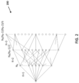
- the DML search algorithm can then be represented using the tree 200 of FIG. 2 .
- the tree structure with depth K represents the search space of all possible combinations of up to K objects. Every node in the tree 200 of FIG. 2 represents a possible set of candidate object DoA angles.
- all possible combinations of DOA angles for 2 objects are represented by each node
- K th vertical layer all possible DOA angle combinations are represented for K objects.
- the tree structure is used to keep track which sets of objects are explored with the DML objective function.
- a branch from the (K-1)th layer to the K-th layer represents the extension of a set of K-1 candidate object's DoA's with an extra candidate DoA.
- the Ne nodes represent the Ne values of the beamforming spectrum, which can be used to find the most likely object in the case of a single object being reflected in the received radar signal.
- the prior-art tree traversal process (illustrated by FIG. 3 and described herein) is consequently called "depth-first" search in coding theory, because first the search in the tree is carried in the depth direction. With such a search, a promising path is extended in the depth of the tree, hence an evaluation of the DML objective function for K objects is followed by the evaluation of the DML objective function for (K+1) objects.
- the Recursive DMLDoA estimation method is based on a recursive formulation of the DML objective function. Assume that the DML objective function is calculated for a set of DoA angles [ ⁇ 1 , ⁇ 2 , ..., ⁇ K ] (K objects) and the algorithm calls for calculating the DML objective for an extra object ⁇ K+1 .
- the DML objective function can then be calculated for a set of DoA angles [ ⁇ 1 , ⁇ 2 , ..., ⁇ K ] including an extra object ⁇ K+1 , which is associated with an additional beamsteering vector a K+1 .
- z y H c .
- y H B y a is a Path Metric
- d (
- ⁇ H B ⁇ ⁇ is the Path Metric of an extended path.
- each node in the tree is associated with a set of candidate object DoA angles.
- the value of the DML objective function can be calculated for each set of object DoA angles.
- a path can be selected through the various nodes in the tree (thereby defining a path) to reach the particular node.
- the path metric can defined as the value of the DML objective function of the corresponding node.
- equation (2) the value of the DML objective function of a certain node can be written as the Path Metric of a previous node/path extended with an extra value.
- This extra value is referred to as the Branch Metric, and that value represents the change in the DML objective function when an extra object DoA is added to the set of candidate object DoA's.
- a difference from conventional approaches i.e., the Viterbi algorithm
- the Viterbi algorithm is usually carried out on a trellis, while the present DoA estimation algorithm can be carried on a tree.
- Another difference is how path merges are dealt with. In the Viterbi algorithm the most likely path is selected as survivor in a node where these paths merge.
- a merging path is a redundant calculation of the DML objective function, i.e., two merging paths will have the same value for the DML objective function because they represent the same set of candidate DoA angles. Therefore, the search on the tree should be organized in such a fashion that these redundant calculations are avoided.
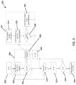
- step 308 is determined when the Branch Metric has a positive value.
- the definition of "success" may be further constrained by requiring that the Branch Metric be larger than some pre-defined positive value. This approach can help in noisy conditions to give favor to sparse solutions of the search: an explanation of the received snapshot with few candidate objects is more likely to be true than an explanation with many candidate obj ects.
- step 304 If, however, in step 304 the path extension does not result in success, the method moves straight to step 310 to determine whether other paths are available to process at the current level D.
- inset 312 provides more detail for the loop including steps 302, 304, and 306.
- steps 314 and 316 represents substeps of step 302.
- path variables A, B, y , and the Path Metric for the current path are determined in a portion of step 302.
- a path extension a K +1 is selected and corresponding values c , d, z, and Branch metric are calculated.
- step 318 (which corresponds to the "success" block of step 314) an evaluation is made of whether the Branch Metric exceeds a predetermined value ⁇ .
- ⁇ has a non-negative value, which might be 0, but in order favor sparse solutions over non-sparse solutions ⁇ may have values greater than 0. If so, the evaluation is successful and the method moves to step 320 (which corresponds to step 306) in which new path variables A, B, y , and a new Path Metric are determined for the successful path.
- step 302 when executing step 302, it is presumed that the following values are known: 1) Path variable A (K beamsteering vectors representing the DoA angles that are hypothesized in the node, 2) Path variable B , 3) Path variable y (Correlation of snapshot with the K beamsteering vectors), and 4) the Path metric representing the FOM-metric of the path that ends in the current node. Additionally, according to a conventional path extension algorithm, the path will be extended with a DoA angle that is represented with a beamsteering vector a K +1 . With the DoA angle of the path extension determined (e.g., via the determination of success step 304), the following calculations are performed unconditionally as part of step 302:
- d 1 a _ K + 1 H a _ K + 1 ⁇ a _ K + 1 H AB A H a _ K + 1 .
- the part B A H a K+1 is available from previous calculation, a _ K + 1 H A can also be read from the alpha LUT and a _ K + 1 H a _ K + 1 is equal to N.
- a ⁇ A a _ K + 1
- Path Metric (new node) Path metric (old node) + d (
- the approach calls for calculating, for each node, a pseudo-spectrum.
- the pseudo-spectrum is the set of complex amplitudes that can be associated with the DoA angles that are hypothesized in a node, i.e., along with estimated DoA angles the pseudo-spectrum provides an estimate of the complex amplitudes of the objects.
- This table can be a 1-Dimensional table when the DoA angles ⁇ to search for are chosen on grid that is uniform in sin( ⁇ ).
- the correlation of the received snapshot x with all possible beamsteering vectors can be carried out prior to the search in order to avoid recalculating these values multiple times during the search, i.e.
- step 310 If, in step 310 it is determined that additional paths remain at depth D within the tree, the method returns to step 302 and a new path extension is designated for evaluation.
- the algorithmic loop formed by step 302, 304, 306, and 308 causes the algorithm to follow successful path extensions down into deeper levels of the tree each time a promising path is identified at a particular level. As those paths become unsuccessful, step 322 moves the algorithm back into higher levels of the tree allowing different paths to be evaluated. Specifically, if in step 310 no paths remain at the current level D (e.g., the algorithm has identified a 'dead-end'), the method moves to step 322 in which the value of depth D is decremented to move the algorithm back higher in the tree to evaluate different paths.
- step 324 a determination is made as to whether the depth D is greater than zero. If so, paths may remain that require exploration. As such, the method moves back to step 310 to identify other paths for evaluation. If, however, in step 324 the current depth D is not greater than zero, that indicates the entire tree has been traversed and the method moves to step 326 in which the best set of DOA angles are output by the algorithm.
- an approach is presented that can optimize the number of nodes visited at each node in the recursive DML algorithm described above.
- a pre-processing approach is presented to reduce the number of nodes that needs to be visited, thus reducing the computation complexity of R-DML.
- the pseudo object spectrum is a vector containing the estimated complex amplitudes of the objects detected so far. Using the pseudo spectrum, it is possible to apply matching pursuit to find the search space for the next node traversal in the depth of the tree as follows.
- a k (of size [N ⁇ N k ] where N k specifies the depth of the tree in which the current node being processed is located.
- the search space is determined by thresholding and picking only the top promising N s nodes from the eta k matched filter response vector.
- FIG. 4 is a flowchart depicting method 400 for implementing an optimized dual object DML approach for DOA estimation, called Fast-DML.
- Method 400 may be implemented by a vehicle radar system (e.g., vehicle radar system 100 of FIG. 1 ) configured to implement MIMO radar signal transmission, reception and processing.
- the radar system receives radar reflections signals (e.g., via receiver units 12 of automotive radar system 100), and processes those signals via various FFTs and other processor (e.g., using radar controller processor 20) to generate Range-Doppler maps where each location in the Range-Doppler maps is associated with a signal snapshot.
- a snapshot is selected from the processed signal received by received elements 12.
- that snapshot can be extended by zero padding to increase the length of the snap shot to a desired length Ne.
- step 406 a FFT of length Ne is executed on the extended snapshot.
- 2 are determined and can be stored in a LUT reference against an identifier of the current snapshot for later use.
- a counter k which identifies a particular path located at a particular depth K within the tree, is initialized to the value 1.
- n is set to a value k +1.
- Variable n is used to explore all Ne paths per node k.
- n is equal to Ne. If so, that indicates all paths have been evaluated and the inner loop formed by steps 418, 420, 422, and 424 is exited. If, however, n is not equal to (i.e., less than) Ne, the method proceeds to step 418 in which the F values for the current path number n (i.e., F n and
- step 424 the value n is incremented and the algorithmic loop of steps 416, 418, 420, and 422 is repeated until all paths have been processed the current object number k. Once all paths have been processed (i.e., the value n is equal to Ne), the method moves to step 426 in which the object counter is incremented and then the method moves to step 410.
- DML objective functions f() are calculated for every combination of 2 objects (up to a maximum of N ⁇ objects) and all paths n (up to a maximum of N ⁇ paths).
- the method moves to step 428 in which a determination is made as to which combination of k and n values resulted in the maximum value of the DML objective function f().
- the radar system can make a determination which 2 objects are the most likely ones explaining the received snapshot.
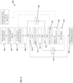
- FIG. 5 is a flowchart depicting method 500 for implementing the proposed approach for optimized R-DMI, for DOA estimation.
- Method 500 may be implemented by a vehicle radar system (e.g., vehicle radar system 100 of FIG. 1 ) configured to implement MIMO radar signal transmission, reception and processing.
- the radar system receives radar reflections signals (e.g., via receiver units 12 of automotive radar system 100), and processes those signals via various FFTs and other processes (e.g., using radar controller processor 20) to generate Range-Doppler maps where each location in the Range-Doppler maps is associated with a signal snapshot.
- a snapshot is selected and, for the selected snapshot, a tree (i.e., of the form of tree 200 of FIG.
- each level of the tree (associated with a depth D) represent a different number of potential objects.
- each node represents a different combination of DOA angles for the each of the number of objects at that particular level.
- a depth variable is initialized to the value 1, indicating that the algorithm begins at depth 1 within the tree processing DOA estimation for a single object.
- variables are calculated for each potential path into deeper levels of the tree associated with additional potential objects.
- a path extension beyond level D in the tree into deeper nodes indicative of additional objects K is selected out of the set of N s promising paths.
- path variables are updated (step 510), the depth counter D is incremented (step 512) and the method continues to step 514 where it is determined whether additional paths are available at the current level D (which has just been incremented).
- step 508 is determined when the Branch Metric has a positive value.
- the definition of "success" may be further constrained by requiring that the Branch Metric be larger than some pre-defined positive value. This approach can help in noisy conditions to give favor to sparse solutions of the search: an explanation of the received snapshot with few candidate objects is more likely to be true than an explanation with many candidate objects.
- step 508 the path extension does not result in success, the method moves straight to step 514 to determine whether other paths are available to process at the current level D.
- inset 516 provides more detail for the loop including steps 506, 508, and 510.
- step 518 provides more detail for step 506.
- a path extension a K+1 is selected from the set of paths Ns and, for the selected path extension, the values c , d, z, and the Branch Metric are calculated.
- Path variable A K beamsteering vectors representing the DoA angles that are hypothesized in the node
- Path variable B 3) Path variable y (Correlation of snapshot with the K beamsteering vectors)
- Path metric representing the FOM-metric of the path that ends in the current node.
- the path will be extended with a DoA angle that is represented with a beamsteering vector a K +1 .
- d 1 a _ K + 1 H a _ K + 1 ⁇ a _ K + 1 H AB A H a _ K + 1 .
- the part B A H a K +1 is available from previous calculation, a _ K + 1 H A can also be read from the alpha LUT and a _ K + 1 H a _ K + 1 is equal to N.
- step 508 If, the determined branch metric for the selected path extension results in success (evaluated in step 508), then the selected path extension is determined to be 'promising' and the path variables and path metric are updated accordingly in step 510:
- a ⁇ A a _ K + 1
- Path Metric (new node) Path metric (old node) + d (
- the set of promising path extensions is then determined as the set N s determined, as desribed herein, using
- N S the set of path extensions to be explored (i.e., N S ) is constrained to only include path extensions with sufficient residual energy (i.e., the magnitude of the vector remaining after the estimated object's power, determined by the current selected path, has been subtracted) to warrant exploration.
- sufficient residual energy i.e., the magnitude of the vector remaining after the estimated object's power, determined by the current selected path, has been subtracted.
- step 514 it is determined whether additional paths remain at depth D within the tree, the method returns to step 506 and a new path extension is selected out of the constrained set N S for evaluation.
- the algorithmic loop formed by steps 506, 508, 510, and 512 causes the algorithm to follow successful path extensions selected out of the constrained set N S down into deeper levels of the tree each time a promising path is identified at a particular level. As those paths become unsuccessful, step 516 moves the algorithm back into higher levels of the tree allowing different paths to be evaluated.
- step 514 if in step 514 no paths remain at the current level D (e.g., the algorithm has identified a 'dead-end'), the method moves to step 524 in which the value of depth D is decremented to move the algorithm back higher in the tree to evaluate different paths.
- step 526 a determination is made as to whether the depth D is greater than zero. If so, paths may remain that require exploration. As such, the method moves back to step 514 to identify other paths for evaluation. If, however, in step 526 the current depth D is not greater than zero, that indicates the promising paths (selected out of the set N S ) of the tree (and not the entire tree as is called for in the method of FIG. 3 ) has been traversed and the method moves to step 528 in which the best set of DOA angles are output by the algorithm.
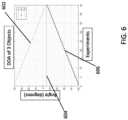
- FIGS. 6 - 8 are graphs depicting the performance of the present optimized R-DMI, approach in comparison with the conventional full search R-DMI, for DOA estimation.
- the horizonal axis represents a number of experiments that are carried out to test the performance of the proposed method and the vertical axis represents DOA angle.
- the traces 602, 604, and 606 shown in FIG. 6 depict the ground truth of three objects in each experiment.
- Object 2, represented by trace 604 is kept constant, object 1 (trace 602) and object 3 (trace 606) are moved close to object 2 (trace 604) in steps of 1 degree for each experiment.
- FIG. 7 depicts the error in DOA estimate for the 3 objects represented in FIG. 6 using both a conventional full search R-DML and the optimized R-DML process of the present disclosure.
- chart 702 represents the error in DOA estimate for the object represented by trace 602 of FIG. 6 .
- Chart 704 represents the error in DOA estimate for the object represented by trace 604 of FIG. 6 .
- Chart 706 represents the error in DOA estimate for the object represented by trace 602 of FIG. 6 .
- the solid line represents DOA algorithm errors when executing a full search.
- the dashed lines represent the DOA algorithm errors when executing a partial search optimized in accordance with the present disclosure. It can be observed that the error seen is similar for both approaches indicating that there is no considerable performance degradation with the reduced search space of the present disclosure.
- FIG. 8 is a chart depicting the number of nodes visited by the conventional exhaustive R-DMI, approach and the present optimized reduced search space approach.
- the horizontal axis of the graph of FIG. 8 represents number of experiments and the vertical axis represents the number of nodes visited.
- Trace 802 represents the number of nodes visited by the conventional algorithm, while trace 804 represents the number of nodes visited by the resent optimized R-DML approach.
- the number of nodes visited is reduced by ⁇ 4.5 times in comparison with R-DML algorithm without any pre-processing step.
- the error slightly increases for both R-DML and optimized R-DMI, as the 3 objects move very close to each other.
- the techniques described herein relate to an automotive radar system, including: at least one transmitter and at least one receiver, wherein the at least one transmitter and the at least one receiver are configured to transmit and receive radar signals, wherein the at least one transmitter and the at least one receiver are coupled to a vehicle; and an automotive radar processor, configured to: transmit, at a first time, a first radar signal, receive, using the at least one receiver, a received signal, process the received signal to generate a plurality of snapshot signals, wherein each snapshot signal in the plurality of snapshot signals is associated with a range-Doppler bin, and execute a direction of arrival analysis of a first snapshot signal of the plurality of snapshot signals, including steps of: determining a hierarchical tree structure, wherein each layer in the hierarchical tree structure is associated with a number of candidate objects and each node in the hierarchical tree structure is associated with a set of direction of arrival angles for the number of candidate objects determined by the layer of the hierarchical tree structure in which the node is located, selecting a first layer in the
- determining the subset of path extensions includes determining path extensions associated with matched filter response vectors having values greater than an average of all matched filter response vectors associated with nodes in the first layer of the hierarchical tree structure.
- the techniques described herein relate to an automotive radar system, wherein the automotive radar processor is configured to determine a beamforming spectrum of the residue value.
- the techniques described herein relate to an automotive radar system, wherein the automotive radar processor is configured to zero pad the first snapshot signal to length N ⁇ and process the first snapshot signal using a fast Fourier transform of length N ⁇ , and N ⁇ defines a grid size of the direction of arrival analysis.
- the techniques described herein relate to an automotive radar system, wherein the automotive radar processor is further configured to: determine the first path extension is associated with a value in the matched filter response vector that is greater than values in the matched filter response vector associated with other path extensions in the subset of path extensions; calculating, for the second layer in the hierarchical tree structure, a second set of path variables, wherein the second set of path variables includes a residue value and a matched filter response vector based upon the residue value; and determining a second subset of second path extensions using the matched filter response vector out of a second set of path extensions that connect to nodes within the hierarchical tree structure associated with a third layer in the hierarchical tree structure and are associated with the first node in the second layer.
- the techniques described herein relate to an automotive radar system, wherein the automotive radar processor is configured to determine, for each path extension in the subset of path extensions, path metric value.
- the techniques described herein relate to an automotive radar system, wherein the path metric values are determined by the deterministic maximum likelihood (DML) objective function of a node in the first layer that is associated with a corresponding path extension.
- DML deterministic maximum likelihood
- the techniques described herein relate to an automotive radar system, wherein the automotive radar processor is configured to determine the path metric values associated with the path extensions in the subset of path extension each exceed a threshold value.
- the techniques described herein relate to a radar system, including: a processor; and a memory. Or to a memory, or other computer-readable storage medium, storing instructions that, when executed by the processor, cause the processor to perform steps including: processing a received radar signal to generate a snapshot signal; determining a hierarchical tree structure using the snapshot signal, wherein each layer in the hierarchical tree structure is associated with a number of candidate objects and each node in the hierarchical tree structure is associated with a set of direction of arrival angles; calculating, for a first layer in the hierarchical tree structure, a first set of path variables; determining a subset of path extensions using the path variables out of a set of path extensions that connect to nodes within the hierarchical tree structure associated with a second layer in the hierarchical tree structure; determining, for a first path extension out of the subset of path extensions, a path metric associated with a first node in the second layer of the hierarchical tree structure; and determining a direction of arrival angle for a
- the techniques described herein relate to a radar system, wherein processor is further configured to determine a beamforming spectrum of a residue value using the first set of path variables.
- the techniques described herein relate to a radar system, wherein the processor is further configured to: determine the first path extension is associated with a value in the matched filter response vector that is greater than values in the matched filter response vector associated with other path extensions in the subset of path extensions; calculating, for the second layer in the hierarchical tree structure, a second set of path variables, wherein the second set of path variables includes a residue value and a matched filter response vector based upon the residue value; and determining a second subset of second path extensions using the matched filter response vector out of a second set of path extensions that connect to nodes within the hierarchical tree structure associated with a third layer in the hierarchical tree structure and are associated with the first node in the second layer.
- the techniques described herein relate to a radar system, wherein the processor is configured to determine, for each path extension in the subset of path extensions, path metric value.
- the techniques described herein relate to a radar system, wherein the path metric values are determined by the deterministic maximum likelihood (DML) objective function of a node in the first layer that is associated with a corresponding path extension.
- DML deterministic maximum likelihood
- the techniques described herein relate to a radar system, wherein the processor is configured to determine the path metric values associated with the path extensions in the subset of path extension each exceed a threshold value.
- the techniques described herein relate to a radar system, wherein the processor is configured use direct correlation of beamsteering vectors to process the first snapshot signal.
- the techniques described herein relate to a method, including: processing a received signal to generate a plurality of snapshot signals, wherein each snapshot signal in the plurality of snapshot signals is associated with a range-Doppler bin, determining a hierarchical tree structure, wherein each layer in the hierarchical tree structure is associated with a number of candidate objects and each node in the hierarchical tree structure is associated with a set of direction of arrival angles for the number of candidate objects determined by the layer of the hierarchical tree structure in which the node is located, selecting a first layer in the hierarchical tree structure, calculating, for the first layer in the hierarchical tree structure, a first set of path variables, wherein the first set of path variables includes a residue value and a matched filter response vector based upon the residue value, determining a subset of path extensions using the matched filter response vector out of a set of path extensions that connect to nodes within the hierarchical tree structure associated with a second layer in the hierarchical tree structure, wherein the second layer is associated with
- determining the subset of path extensions includes determining path extensions associated with matched filter response vectors having values greater than an average of all matched filter response vectors associated with nodes in the first layer of the hierarchical tree structure.
- the techniques described herein relate to a method, further including: determining the path variables include a beamsteering matrix; and calculating the matched filter response vector using the expression AH rk in which is rk the residue value and A is a beamsteering matrix.
Landscapes
- Engineering & Computer Science (AREA)
- Radar, Positioning & Navigation (AREA)
- Remote Sensing (AREA)
- Physics & Mathematics (AREA)
- Computer Networks & Wireless Communication (AREA)
- General Physics & Mathematics (AREA)
- Electromagnetism (AREA)
- Radar Systems Or Details Thereof (AREA)
Applications Claiming Priority (1)
| Application Number | Priority Date | Filing Date | Title |
|---|---|---|---|
| US18/394,386 US12585007B2 (en) | 2023-12-22 | 2023-12-22 | Recursive deterministic maximum likelihood estimation of direction of arrival in automotive radar sensing |
Publications (1)
| Publication Number | Publication Date |
|---|---|
| EP4575554A1 true EP4575554A1 (de) | 2025-06-25 |
Family
ID=93923907
Family Applications (1)
| Application Number | Title | Priority Date | Filing Date |
|---|---|---|---|
| EP24219911.5A Pending EP4575554A1 (de) | 2023-12-22 | 2024-12-13 | Rekursive deterministische maximalwahrscheinlichkeitsschätzung der einfallsrichtung bei der kraftfahrzeugradarerfassung |
Country Status (2)
| Country | Link |
|---|---|
| US (1) | US12585007B2 (de) |
| EP (1) | EP4575554A1 (de) |
Citations (1)
| Publication number | Priority date | Publication date | Assignee | Title |
|---|---|---|---|---|
| EP4345493A1 (de) * | 2022-09-27 | 2024-04-03 | Nxp B.V. | Verfahren und vorrichtung zur bestimmung der richtung des ankunftswinkels |
Family Cites Families (4)
| Publication number | Priority date | Publication date | Assignee | Title |
|---|---|---|---|---|
| US10591586B2 (en) * | 2017-07-07 | 2020-03-17 | Infineon Technologies Ag | System and method for identifying a target using radar sensors |
| DE102020109405A1 (de) | 2020-04-03 | 2021-10-07 | HELLA GmbH & Co. KGaA | Verfahren zur Bestimmung einer Richtungsinformation von Zielobjekten bei einem Radarsystem für ein Fahrzeug |
| WO2022139783A1 (en) * | 2020-12-21 | 2022-06-30 | Intel Corporation | High end imaging radar |
| EP4137844B1 (de) | 2021-08-20 | 2026-06-17 | Nxp B.V. | Verfahren und vorrichtung zur bestimmung eines einfallswinkels |
-
2023
- 2023-12-22 US US18/394,386 patent/US12585007B2/en active Active
-
2024
- 2024-12-13 EP EP24219911.5A patent/EP4575554A1/de active Pending
Patent Citations (1)
| Publication number | Priority date | Publication date | Assignee | Title |
|---|---|---|---|---|
| EP4345493A1 (de) * | 2022-09-27 | 2024-04-03 | Nxp B.V. | Verfahren und vorrichtung zur bestimmung der richtung des ankunftswinkels |
Non-Patent Citations (1)
| Title |
|---|
| KOPPELAAR ARIE G C ET AL: "Sequential DoA estimation using Recursive DML", 2024 21ST EUROPEAN RADAR CONFERENCE (EURAD), EUROPEAN MICROWAVE ASSOCIATION (EUMA), 25 September 2024 (2024-09-25), pages 188 - 191, XP034745443, DOI: 10.23919/EURAD61604.2024.10734932 * |
Also Published As
| Publication number | Publication date |
|---|---|
| US12585007B2 (en) | 2026-03-24 |
| US20250208282A1 (en) | 2025-06-26 |
Similar Documents
| Publication | Publication Date | Title |
|---|---|---|
| US11815585B2 (en) | Method and system for time division multiplexing MIMO radar doppler compensation using spurious angle spectrum hypothesis tests | |
| US9470782B2 (en) | Method and apparatus for increasing angular resolution in an automotive radar system | |
| US10768276B2 (en) | Decentralised radar system | |
| US11754673B2 (en) | Cell-average and ordered-statistic of cell-average CFAR algorithms for log detectors | |
| US12345797B2 (en) | Super-resolution MIMO sparse array automotive radar based on forward and backward hankel matrix completion | |
| CN114966657A (zh) | 使用稀疏阵列处理的基于雷达的检测 | |
| CN107688178A (zh) | 一种基于77GHz毫米波雷达的锯齿波测距测速方法 | |
| WO2008093036A2 (en) | Adaptive radar | |
| US20240111020A1 (en) | Near-range interference mitigation for automotive radar system | |
| EP4053592B1 (de) | Verfahren und system zur einzelziel-ankunftsrichtungsabschätzung für radarsysteme mit verdünnten arrays | |
| US20230288579A1 (en) | Radio frequency (rf) ranging in propagation limited rf environments utilizing aerial vehicles | |
| US12510618B2 (en) | Method and apparatus for determination of direction of arrival angle | |
| CN115856866A (zh) | 利用不同脉冲重复频率组的雷达通信 | |
| EP4345493B1 (de) | Verfahren und vorrichtung zur bestimmung der richtung des ankunftswinkels | |
| US12292496B2 (en) | Method and device for determining an angle of a target object | |
| US12442895B2 (en) | Determining reliability of a direction of arrival (DOA) of a signal received by a radar system from a source and apparatus for determining reliability | |
| US12585007B2 (en) | Recursive deterministic maximum likelihood estimation of direction of arrival in automotive radar sensing | |
| WO2023043818A2 (en) | Methods and systems for processing radar signals to determine relative position and motion of nearby objects | |
| US20260036673A1 (en) | Automotive radar system with interference suppression | |
| EP4524613A1 (de) | Radarsystemsenderstrahlformung unter verwendung von belegungskartendaten | |
| US5231403A (en) | Moving target indicator using higher order statistics | |
| EP4653909A1 (de) | Schätzung des ankunftswinkels für ein kraftfahrzeugradarsystem | |
| EP4417998B1 (de) | Verfahren zur schätzung des feinen nahbereichs für kraftfahrzeugradaranwendungen | |
| US20260118502A1 (en) | Multi-radar joint detection system | |
| US20260118477A1 (en) | Radar system and testing method with interference detection |
Legal Events
| Date | Code | Title | Description |
|---|---|---|---|
| PUAI | Public reference made under article 153(3) epc to a published international application that has entered the european phase |
Free format text: ORIGINAL CODE: 0009012 |
|
| STAA | Information on the status of an ep patent application or granted ep patent |
Free format text: STATUS: THE APPLICATION HAS BEEN PUBLISHED |
|
| AK | Designated contracting states |
Kind code of ref document: A1 Designated state(s): AL AT BE BG CH CY CZ DE DK EE ES FI FR GB GR HR HU IE IS IT LI LT LU LV MC ME MK MT NL NO PL PT RO RS SE SI SK SM TR |
|
| STAA | Information on the status of an ep patent application or granted ep patent |
Free format text: STATUS: REQUEST FOR EXAMINATION WAS MADE |
|
| 17P | Request for examination filed |
Effective date: 20260102 |
|
| GRAP | Despatch of communication of intention to grant a patent |
Free format text: ORIGINAL CODE: EPIDOSNIGR1 |
|
| STAA | Information on the status of an ep patent application or granted ep patent |
Free format text: STATUS: GRANT OF PATENT IS INTENDED |
|
| RIC1 | Information provided on ipc code assigned before grant |
Ipc: G01S 7/35 20060101AFI20260629BHEP Ipc: G01S 13/42 20060101ALI20260629BHEP Ipc: G01S 13/58 20060101ALI20260629BHEP Ipc: G01S 13/931 20200101ALN20260629BHEP |