EP4575510A1 - Dispensing device, and genetic test device provided with same - Google Patents
Dispensing device, and genetic test device provided with same Download PDFInfo
- Publication number
- EP4575510A1 EP4575510A1 EP22955775.6A EP22955775A EP4575510A1 EP 4575510 A1 EP4575510 A1 EP 4575510A1 EP 22955775 A EP22955775 A EP 22955775A EP 4575510 A1 EP4575510 A1 EP 4575510A1
- Authority
- EP
- European Patent Office
- Prior art keywords
- lanes
- dispensing device
- ribs
- dispensing
- spaces
- Prior art date
- Legal status (The legal status is an assumption and is not a legal conclusion. Google has not performed a legal analysis and makes no representation as to the accuracy of the status listed.)
- Pending
Links
Images




Classifications
-
- G—PHYSICS
- G01—MEASURING; TESTING
- G01N—INVESTIGATING OR ANALYSING MATERIALS BY DETERMINING THEIR CHEMICAL OR PHYSICAL PROPERTIES
- G01N35/00—Automatic analysis not limited to methods or materials provided for in any single one of groups G01N1/00 - G01N33/00; Handling materials therefor
- G01N35/10—Devices for transferring samples or any liquids to, in, or from, the analysis apparatus, e.g. suction devices, injection devices
- G01N35/1065—Multiple transfer devices
-
- B—PERFORMING OPERATIONS; TRANSPORTING
- B01—PHYSICAL OR CHEMICAL PROCESSES OR APPARATUS IN GENERAL
- B01L—CHEMICAL OR PHYSICAL LABORATORY APPARATUS FOR GENERAL USE
- B01L3/00—Containers or dishes for laboratory use, e.g. laboratory glassware; Droppers
- B01L3/02—Burettes; Pipettes
- B01L3/021—Pipettes, i.e. with only one conduit for withdrawing and redistributing liquids
-
- G—PHYSICS
- G01—MEASURING; TESTING
- G01N—INVESTIGATING OR ANALYSING MATERIALS BY DETERMINING THEIR CHEMICAL OR PHYSICAL PROPERTIES
- G01N35/00—Automatic analysis not limited to methods or materials provided for in any single one of groups G01N1/00 - G01N33/00; Handling materials therefor
- G01N35/10—Devices for transferring samples or any liquids to, in, or from, the analysis apparatus, e.g. suction devices, injection devices
- G01N35/1002—Reagent dispensers
-
- G—PHYSICS
- G01—MEASURING; TESTING
- G01N—INVESTIGATING OR ANALYSING MATERIALS BY DETERMINING THEIR CHEMICAL OR PHYSICAL PROPERTIES
- G01N35/00—Automatic analysis not limited to methods or materials provided for in any single one of groups G01N1/00 - G01N33/00; Handling materials therefor
- G01N35/10—Devices for transferring samples or any liquids to, in, or from, the analysis apparatus, e.g. suction devices, injection devices
- G01N35/1009—Characterised by arrangements for controlling the aspiration or dispense of liquids
-
- G—PHYSICS
- G01—MEASURING; TESTING
- G01N—INVESTIGATING OR ANALYSING MATERIALS BY DETERMINING THEIR CHEMICAL OR PHYSICAL PROPERTIES
- G01N35/00—Automatic analysis not limited to methods or materials provided for in any single one of groups G01N1/00 - G01N33/00; Handling materials therefor
- G01N35/10—Devices for transferring samples or any liquids to, in, or from, the analysis apparatus, e.g. suction devices, injection devices
- G01N35/1009—Characterised by arrangements for controlling the aspiration or dispense of liquids
- G01N35/1011—Control of the position or alignment of the transfer device
-
- G—PHYSICS
- G01—MEASURING; TESTING
- G01N—INVESTIGATING OR ANALYSING MATERIALS BY DETERMINING THEIR CHEMICAL OR PHYSICAL PROPERTIES
- G01N35/00—Automatic analysis not limited to methods or materials provided for in any single one of groups G01N1/00 - G01N33/00; Handling materials therefor
- G01N35/10—Devices for transferring samples or any liquids to, in, or from, the analysis apparatus, e.g. suction devices, injection devices
- G01N35/1081—Devices for transferring samples or any liquids to, in, or from, the analysis apparatus, e.g. suction devices, injection devices characterised by the means for relatively moving the transfer device and the containers in an horizontal plane
-
- B—PERFORMING OPERATIONS; TRANSPORTING
- B01—PHYSICAL OR CHEMICAL PROCESSES OR APPARATUS IN GENERAL
- B01L—CHEMICAL OR PHYSICAL LABORATORY APPARATUS FOR GENERAL USE
- B01L2200/00—Solutions for specific problems relating to chemical or physical laboratory apparatus
- B01L2200/06—Fluid handling related problems
- B01L2200/0647—Handling flowable solids, e.g. microscopic beads, cells, particles
- B01L2200/0663—Stretching or orienting elongated molecules or particles
-
- B—PERFORMING OPERATIONS; TRANSPORTING
- B01—PHYSICAL OR CHEMICAL PROCESSES OR APPARATUS IN GENERAL
- B01L—CHEMICAL OR PHYSICAL LABORATORY APPARATUS FOR GENERAL USE
- B01L2200/00—Solutions for specific problems relating to chemical or physical laboratory apparatus
- B01L2200/14—Process control and prevention of errors
- B01L2200/141—Preventing contamination, tampering
-
- B—PERFORMING OPERATIONS; TRANSPORTING
- B01—PHYSICAL OR CHEMICAL PROCESSES OR APPARATUS IN GENERAL
- B01L—CHEMICAL OR PHYSICAL LABORATORY APPARATUS FOR GENERAL USE
- B01L2300/00—Additional constructional details
- B01L2300/08—Geometry, shape and general structure
- B01L2300/0809—Geometry, shape and general structure rectangular shaped
- B01L2300/0829—Multi-well plates; Microtitration plates
-
- B—PERFORMING OPERATIONS; TRANSPORTING
- B01—PHYSICAL OR CHEMICAL PROCESSES OR APPARATUS IN GENERAL
- B01L—CHEMICAL OR PHYSICAL LABORATORY APPARATUS FOR GENERAL USE
- B01L2300/00—Additional constructional details
- B01L2300/08—Geometry, shape and general structure
- B01L2300/0861—Configuration of multiple channels and/or chambers in a single devices
-
- B—PERFORMING OPERATIONS; TRANSPORTING
- B01—PHYSICAL OR CHEMICAL PROCESSES OR APPARATUS IN GENERAL
- B01L—CHEMICAL OR PHYSICAL LABORATORY APPARATUS FOR GENERAL USE
- B01L7/00—Heating or cooling apparatus; Heat insulating devices
- B01L7/52—Heating or cooling apparatus; Heat insulating devices with provision for submitting samples to a predetermined sequence of different temperatures, e.g. for treating nucleic acid samples
-
- C—CHEMISTRY; METALLURGY
- C12—BIOCHEMISTRY; BEER; SPIRITS; WINE; VINEGAR; MICROBIOLOGY; ENZYMOLOGY; MUTATION OR GENETIC ENGINEERING
- C12Q—MEASURING OR TESTING PROCESSES INVOLVING ENZYMES, NUCLEIC ACIDS OR MICROORGANISMS; COMPOSITIONS OR TEST PAPERS THEREFOR; PROCESSES OF PREPARING SUCH COMPOSITIONS; CONDITION-RESPONSIVE CONTROL IN MICROBIOLOGICAL OR ENZYMOLOGICAL PROCESSES
- C12Q1/00—Measuring or testing processes involving enzymes, nucleic acids or microorganisms; Compositions therefor; Processes of preparing such compositions
- C12Q1/68—Measuring or testing processes involving enzymes, nucleic acids or microorganisms; Compositions therefor; Processes of preparing such compositions involving nucleic acids
- C12Q1/6844—Nucleic acid amplification reactions
- C12Q1/686—Polymerase chain reaction [PCR]
-
- G—PHYSICS
- G01—MEASURING; TESTING
- G01N—INVESTIGATING OR ANALYSING MATERIALS BY DETERMINING THEIR CHEMICAL OR PHYSICAL PROPERTIES
- G01N35/00—Automatic analysis not limited to methods or materials provided for in any single one of groups G01N1/00 - G01N33/00; Handling materials therefor
- G01N2035/00178—Special arrangements of analysers
- G01N2035/00207—Handling bulk quantities of analyte
-
- G—PHYSICS
- G01—MEASURING; TESTING
- G01N—INVESTIGATING OR ANALYSING MATERIALS BY DETERMINING THEIR CHEMICAL OR PHYSICAL PROPERTIES
- G01N35/00—Automatic analysis not limited to methods or materials provided for in any single one of groups G01N1/00 - G01N33/00; Handling materials therefor
- G01N2035/00346—Heating or cooling arrangements
- G01N2035/00356—Holding samples at elevated temperature (incubation)
- G01N2035/00366—Several different temperatures used
-
- G—PHYSICS
- G01—MEASURING; TESTING
- G01N—INVESTIGATING OR ANALYSING MATERIALS BY DETERMINING THEIR CHEMICAL OR PHYSICAL PROPERTIES
- G01N35/00—Automatic analysis not limited to methods or materials provided for in any single one of groups G01N1/00 - G01N33/00; Handling materials therefor
- G01N35/02—Automatic analysis not limited to methods or materials provided for in any single one of groups G01N1/00 - G01N33/00; Handling materials therefor using a plurality of sample containers moved by a conveyor system past one or more treatment or analysis stations
- G01N35/04—Details of the conveyor system
- G01N2035/0439—Rotary sample carriers, i.e. carousels
- G01N2035/0444—Rotary sample carriers, i.e. carousels for cuvettes or reaction vessels
-
- G—PHYSICS
- G01—MEASURING; TESTING
- G01N—INVESTIGATING OR ANALYSING MATERIALS BY DETERMINING THEIR CHEMICAL OR PHYSICAL PROPERTIES
- G01N35/00—Automatic analysis not limited to methods or materials provided for in any single one of groups G01N1/00 - G01N33/00; Handling materials therefor
- G01N35/10—Devices for transferring samples or any liquids to, in, or from, the analysis apparatus, e.g. suction devices, injection devices
- G01N2035/1027—General features of the devices
- G01N2035/1048—General features of the devices using the transfer device for another function
Definitions
- the present invention relates to a multi-dispensing device which simultaneously handles a plurality of samples and a genetic testing device provided therewith and relates to a dispensing device which reduces a risk of cross contamination and a genetic testing device provided therewith.
- Patent Document 1 there is described a technology of including a multi-dispensing device which simultaneously handles a plurality of samples and using an independent reagent cartridge having a partition wall to manage each sample, thereby suppressing entry, to a solution containing another sample, of fine particles containing the sample and hence possibly causing cross contamination.
- Patent Document 1 Japanese Patent No. 3630493
- the dispensing device is a device which suctions and discharges such liquid as a sample or a reagent in a determined amount in research, a test, or the like in the life science field.
- a dispensing device mounted to a genetic testing device a multi-dispensing device is used to be able to simultaneously test different samples.
- the multi-dispensing device is formed by disposing a plurality of independent dispensing machines in parallel.
- PCR polymerase chain reaction
- Patent Document 1 there is described a structure which provides, when a plurality of rows of reaction lines (hereinafter referred to as lanes) for executing series of reaction processing for one sample are disposed side by side, partition walls for partitioning a space from an adjacent lane as well as air suction openings between the lanes for downward suctioning.
- lanes rows of reaction lines
- partition walls for partitioning a space from an adjacent lane as well as air suction openings between the lanes for downward suctioning.
- Patent Document 1 is a structure which suppress, through the partition walls and the suction from the air suction openings, scattering of the fine particles, which contain the sample and possibly cause the cross contamination, toward an unintended direction and can easily be implemented through a cartridge structure which is independent for each lane. That is, it is only required to provide the partition wall at any one of left and right ends of a cartridge upper surface. By disposing such cartridges side by side in a lateral direction, a gap into which the air can flows is easily formed between the cartridges.
- the device configuration and control can be simplified by integrating the individual cartridges for each lane, but an aluminum seal for sealing a reagent or the like is applied to a surface of the cartridge, and hence, it is difficult to form the partition walls and the air suction openings described in Patent Document 1. It is thus difficult to suppress the movement of the fine particles that contain the sample between the lanes and that possibly cause the cross contamination, and hence, there poses a problem of an increase in risk.
- the present invention provides a dispensing device and a genetic testing device provided therewith which solve the problem of the prior art described above, the dispensing device reducing, when cartridges for reaction formed as a plurality of lanes are integrated, a risk of occurrence of cross contamination without providing, on the cartridges, partition walls for partitioning the lanes and air suction openings.
- a dispensing device includes a plurality of dispensing machines, a dispensing device body that has the plurality of dispensing machines mounted thereto and is capable of moving along a direction of a plurality of lanes of a solution plate including a plurality of containers each of which accommodates a reagent or a sample and that are integrally formed along the lanes, a top plate for test on which the dispensing device body and the solution plate are placed, and a device cover that covers the dispensing device body in combination with the top plate for test, in which a plurality of ribs that separate a space above the plurality of lanes of the container plate into spaces each for each lane of the plurality of lanes and cover the spaces are formed in the dispensing device body.
- a genetic testing device includes a DNA detection unit, a DNA amplification unit that amplifies a detection target detected by the DNA detection unit, an amplicon detection unit that quantitatively evaluates an amplification amount of the detection target amplified by the DNA amplification unit, a control unit that controls the DNA detection unit, the DNA amplification unit, and the amplicon detection unit, and an output unit that outputs a result of the quantitative evaluation of the amplification amount of the detection target performed by the amplicon detection unit
- the DNA detection unit includes a dispensing device that dispenses a solution containing the detection target and a reagent to a container
- the dispensing device includes a plurality of dispensing machines, a dispensing device body that has the plurality of dispensing machines mounted thereto and is capable of moving along a direction of a plurality of lanes of a solution plate including a plurality of containers each of which accommodates a reagent
- the plate formed by integrating reagent/solution cartridges corresponding to a plurality of samples, and hence, the risk of cross contamination can be reduced without providing partition walls, air suction openings, and the like on a solution cartridge surface.
- test lanes are disposed in parallel to simultaneously test a plurality of samples.
- dispensing machines which simultaneously inject samples or reagents into a solution plate corresponding to a plurality of test lanes accompany discharging/stirring by the dispensing machines and movements of the dispensing machines. At this time, there possibly occurs cross contamination in which fine particles are scattered by an airflow and are mixed with other samples.
- the present invention has such a configuration that wall-surface rib structures are provided in a portion positioned below dispensing machines and opposing a solution plate to form a guide for an airflow to separate flows from each other, thereby suppressing the cross contamination of the fine particles in the dispensing machines.
- the present invention provides a dispensing device which integrates reagent/solution cartridges corresponding to a plurality of samples and can reduce a risk of cross contamination without providing, on a solution cartridge surface, partition walls, air suction openings, and the like and a genetic testing device provided therewith.
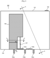
- FIG. 1 illustrates a schematic configuration of a dispensing device 100 according to the first embodiment used for a genetic testing device and the like.
- the dispensing device 100 is formed by a dispensing device body 106, to which a plurality of dispensing machines 107 are mounted, being covered with a top plate 103 for test and a device cover 101.
- an intake opening 102 which causes the air to flow inward from the outside of the device is provided.
- On the top plate 103 for test there are disposed, in addition to exhaust openings 104a to 104c for exhausting, by unillustrated exhaust mean, the air inside the device including the dispensing device body 106 covered with the device cover 101, a solution plate 105a for accommodating reagents and the like for executing test processing and a solution plate 105b for accommodating samples.
- the solution plate 105a functions similarly to conventional solution cartridges described in Patent Document 1, but does not include individual cartridges for each reaction lane 210, and a large number of containers 1051 for accommodating the solution for executing the test processing are formed in each of a length direction and a width direction and are integrated, as illustrated in FIG. 2 . Moreover, in the solution plate 105b, a large number of containers 1052 for accommodating the samples are formed and are integrated. It is assumed that the disposition of the solution plate 105a for executing the test processing and the solution plate 105b for accommodating the samples can be changed as desired according to a sequence of the test processing and the device configuration.
- the exhaust openings 104a to 104c can each have a duct structure formed of, for example, a member in a plate shape made of metal, resin, or the like, and may also be a flow passage, such as a gap between members, which appears as a result of construction of the device and through which an airflow passes.
- the dispensing device body 106 has the plurality of the dispensing machines 107 mounted thereto as described in FIG. 2 and is configured to be movable in a left-right direction of the page of FIG. 1 .
- the dispensing machines 107 move as the dispensing device body 106 moves in the left-right direction.
- the dispensing machine 107 is configured to be movable in the up-down direction of the page of FIG. 1 and has a function of dispensing liquid.
- the dispensing machine 107 has a function of, in cooperation with movement control for the dispensing device body 106 described before, suctioning a certain quantity of the sample or the reagent, for example, accommodated in the container of any one of the solution plates 105a and 105b and discharging the sample or the reagent, for example, in another container.
- the dispensing machine 107 may have a discharging/stirring function of repeating the suction and the discharge of the liquid accommodated in the container of any one of the solution plates 105a and 105b and thereby mixing the liquid.
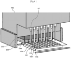
- a rectangle 210 in a dotted line indicates the reaction lane 210 in the present embodiment, and one sample is processing within one reaction lane 210. It is assumed that the present embodiment has such a configuration as the solution plate 105a in which the plurality of containers 1051 which accommodate the reagents and the solutions required for the processing for the reaction lane 210 are integrally formed, which is different from the solution cartridges described in Patent Document 1. Similarly, it is assumed that the solution plate 105b which holds sample solutions also has such a configuration that the plurality of containers 1052 are integrally formed.
- a structure 202 including magnets and the like required for a sample operation using magnetic particles in the reaction processing.
- a plurality of rib structures 203 which extend in a vertical direction with respect to a bottom surface of the structure 202 are formed on a side of the structure 202 and are disposed in such a manner as to partition a space for each reaction lane 210.
- the rib structures 203 are disposed in such a manner as to partition, for each reaction lane 201, a space between an upper surface of the solution plate 105a and the bottom surface of the structure 202.
- the solution plates 105a and 105b, as well as other components required for the genetic testing device, and the rib structures 203 are required to be disposed in such a manner as to avoid interference at the time of operation. For example, it is required to maintain a certain distance between the solution plates 105a and 105b and lower ends of the rib structures 203 to avoid contact. However, as described later, in order to form the space below the structure 202 as spaces independent of each other as much as possible for each reaction lane 210, it is desired that the distance between the lower ends of the rib structures 203 and the solution plate 105a be short.
- a length L of the rib structures 203 is set such that a cross-sectional area of a space 204 surrounded by the bottom surface of the structure 202 including the magnets and the like and the rib structures 203 adjacent to each other is sufficiently wider than a cross-sectional area of a space 205 formed of a surface formed by the lower ends of the rib structures 203 adjacent to each other being connected to each other and the surface of the solution plate 105a.
- the airflow passing below the structure 202 substantially passes through the space 204 for each reaction lane 210, and hence, it is possible to separate the airflow for each reaction lane.
- FIG. 4 is a perspective view of a periphery of the dispensing device body 106 in FIG. 2 .
- the airflow over the solution plate 105a is straightened by the rib structures 203 and hence flows substantially along the reaction lane 210 as an arrow 301 indicates.
- This airflow is a part of a flow structure which flows into the device from the intake opening 102, illustrated in FIG. 1 , for causing the air to flow from the outside of the device to the inside and flows out from the exhaust openings 104a, 104b, and 104c.
- fine particles possibly generated by scattering of the solution that is attached to a distal end of the dispensing machine 107 and that contains the sample and fine particles possibly generated at the time of processing executed on the solution plate 105a, that is, fine particles possibly constituting a cross-contamination source, can be guided by the airflow flowing toward a direction of the arrow 301 and can be collected from the exhaust opening 104a.
- the rib structures 203 are installed on the bottom surface of the structure 202 including the magnets and the like, and the upper surfaces of the solution plates 105a and 105b can thus be flat, so that the plurality of solution plates 105a or 105b can be stored in a stacked state.
- a storage space for the plurality of solution plates 105a or 105b can be smaller than that in a case in which the upper surface is not flat.
- the structure 202 when the rib structures 203 are installed on the bottom surface of the structure 202 including the magnets and the like, the structure 202 may be made of metal, and the rib structures 203 may be cut, thereby integrally forming the rib structures 203 with the structure 202.
- the rib structures 203 may be formed independently of the structure 202, and each rib structure 203 may be formed of a component in a plate form bent into an L shape. In this case, the components bent into the L shape may be adhered to or fixed through screws or the like to the structure 202 to form the rib structures 203.
- the rib structure 203 can be configured to be detached from the structure 202 by sliding the rib structure 203.
- the shape of the rib structure 203 is a rectangular parallelepiped, and hence, the cross-sectional shape of the space formed by the rib structures 203 adjacent to each other is substantially rectangular.
- the cross-sectional shape of the rib structure 203 may also be changed as desired according to necessity. For example, there can be made such a change that a joined portion between the structure 202 and the rib structure 203 has a fillet shape.
- the cross-sectional shape may be changed for each reaction lane 210, thereby being able to change a cross-sectional area distribution.
- the present embodiment focuses on the rib structures 203 according to the first embodiment and achieves balance among flow passage resistances of the spaces formed of the rib structures 203 for the reaction lanes 210, thereby effectively uniformizing the flowrates.
- FIG. 5 illustrates a configuration in the second embodiment corresponding to the rib structures 203 on the cross section made on a plane indicated by B-B of FIG. 1 and a configuration of a periphery of the exhaust opening 104a.
- rib structures 401a and 401b which are among the rib structures 410 and correspond to the reaction lanes 210 at left and right ends among the plurality of reaction lanes 210 formed on the solution plate 105a are thick rib structures
- the rib structures 401c which partition the spaces for the reaction lanes 210 on the inner side of the reaction lanes 210 at the left and right ends (inner reaction lanes 210 between the reaction lanes 210 at the left and right ends) are relatively thin rib structures.
- a width W1 of the flow passage 402a for each of the reaction lanes 210 at the left and right ends among the plurality of reaction lanes 210 is wider than a width W2 of the reaction lanes 210 on the inner side of the reaction lanes 210 at the left and right ends, and hence, a flow passage cross sectional area of the flow passage 402a of each of the reaction lanes 210 at the left and right ends is wider than a flow passage cross sectional area of the flow passage 402b of each of the reaction lanes 210 on the inner side of the reaction lanes 210 at the left and right ends.
- the pressure loss is large at left and right ends in a length direction (left-right direction in FIG. 5 ), and hence, the air less likely to flow.
- the rib structures 410 described in the present embodiment it is possible to balance the pressure losses in the flow passages in which air flows from the reaction lanes 210 and passes through the exhaust opening 104a.
- the cross-sectional shapes of the reaction lanes 210 may be changed to have a distribution of the cross-sectional area, thereby being able to adjust the pressure losses of the flow passages.
- An example is illustrated in FIG. 6 .
- rib structures 501c corresponding to the rib structures 401a and 401b corresponding to the reaction lanes 210 at the left and right ends illustrated in FIG. 5 are connected to each other through a block 501d on a housing inner side to fill the space.
- the rib structures 501a and 501b corresponding to the left and right ends of the reaction lanes 210 do not fill the space on the housing inner side.
- the dispensing device body 106 including the rib structures 501 illustrated in FIG. 6 moves toward directions of an arrow 503.
- the position of the dispensing machine effective as the flow passage can be controlled for each reaction lane 210.
- the flow passage cross-sectional areas of the flow passages 502a and 502b of the reaction lanes 210 at the left and right ends are constant, but the flow passages 502c of the inner reaction lanes 210 between the reaction lanes 210 at the left and right ends are restricted according to the position of the dispensing device body 106, so that the flow passage cross-sectional areas decrease, and the flow passage resistances increase. As a result, it is possible to control the pressure loss in the flow passage for each reaction lane 210, thereby being able to flexibly control the airflow.
- the thickness of the rib structures 401a and 401b are thinner than the thickness of the rib structures 402c on the inner side is described, but the configuration is not limited to this example, and, as long as the width W1 of the flow passages 402a of the reaction lanes 210 at the left and right ends can be set to be wider than the width W2 of the reaction lanes 210 on the inner side of the reaction lanes 210 at the left and right ends, the thickness of the rib structures 401a and 401b may be the same as or thicker than that of the rib structures 402c on the inner side of the reaction lanes 210 at the left and right ends. The same applies to the configuration described in FIG. 6 .
- the present embodiment focuses on the structure 202 including the magnets and the rib structures 203 in the first embodiment, and the airflows passing through the space formed by the structure 202 and the rib structures 203 are more effectively straightened.
- FIG. 7 illustrates the configuration of the structure 202 including magnets and rib structures 601 in the third embodiment. This configuration is the same as that of the first embodiment in such a point that the space below the bottom surface of the structure 202 including the magnets is partitioned for each reaction lane 210 (see FIG. 2 ) by disposing the rib structures 601 on the bottom surface of the structure 202.
- a position the same as a front surface of the structure 202 is set to distal end portions 6011a and 6011b of the rib structures 601a and 601b, respectively.
- distal end portions 6011c are set to a position closer to the dispensing machines 107.
- the distal end portions 6011c of the inner-side rib structures 601c protrude toward the side of the dispensing machines 107 more than the distal end portions 6011a and 6011b of the rib structures 601a and 601b at the left and right ends.
- the straightening effect for each reaction lane 210 can be exerted from the upstream side of the airflow on which the fine particles constituting the cross-contamination source are generated due to the influence of the airflow and the like during the test processing and which hence highly probably constitutes the scattering source.
- the present embodiment focuses on the exhaust opening 104a in a device rear portion in the first embodiment and more effectively straightens the airflow passing through the space formed by the structure 202 and the rib structures 203 described in FIG. 2 .
- FIG. 8 illustrates a configuration of the rib structures 203 and a periphery of an exhaust opening 701 in the fourth embodiment and corresponds to a configuration of the rib structures 203 and the periphery of the exhaust opening 104a as viewed from the cross section indicated by the arrows C-C illustrated in FIG. 1 in the first embodiment.
- the configurations of the rib structures 203, the solution plate 105a, and the dispensing machines 107 in FIG. 8 are the same as those described in the first embodiment.
- the exhaust opening 701 in the present embodiment has a flow passage shape having an opening shape changing in a device left-right direction (left-right direction of the page) as opening regions 7011 and 7012.
- the airflow which passes through a reaction lane 702a at the left end substantially passes through the opening region 7011 having a wide flow passage area of the exhaust opening 701
- the airflow which passes through an adjacent reaction lane 702b substantially passes through the opening region 7012 having a narrow flow passage area of the exhaust opening 701.
- the pressure loss is relatively large at both ends in the length direction of a rectangular pipeline, while the pressure loss is small in a vicinity of the center.
- the pressure loss can be balanced. Therefore, it is possible to uniformize the flowrates of the airflow 703a passing through the lane at the left end and the airflow 703b passing through the adjacent lane, and hence, it is possible to carry, on the stabilized airflows, the fine particles that contain the sample and the like and that constitute the cross-contamination source, thereby more efficiently collecting the fine particles.
- FIG. 8 there is illustrated an example in which a flow passage cross sectional area of the exhaust opening 701 changes stepwise in the device left-right direction, but the flow passage cross sectional area may have any shape, and may have a flow passage cross sectional area distribution which changes continuously.
- the exhaust opening 701 may be configured as a hole provided to the top plate 103 for test (see FIG. 1 ) as well as a duct formed of resin, metal, or the like.
- the exhaust opening 701 may be configured such that an entire region thereof is formed at a width of the opening region 7011 and a member which increases an air resistance, for example, a mesh plate, may be installed in a portion corresponding to the opening region 7012.
- a member which increases an air resistance for example, a mesh plate
- the present embodiment is an example in which the dispensing device 100 described in any one of the first embodiment to the fourth embodiment is applied to a genetic testing device (hereinafter referred to as a PCR device) 800 which uses the PCR reaction.
- a PCR device 800 which uses the PCR reaction.
- the dispensing devices 100 described herein include the dispensing devices obtained by making the changes as described in the second embodiment to the fourth embodiment to the dispensing device 100 described in the first embodiment.
- FIG. 9 is a schematic configuration of the PCR device 800 which uses the dispensing device 100 in the fifth embodiment.
- the PCR device 800 includes a DNA extraction unit 801 provided with the dispensing device 100, a DNA amplification unit 802, an amplicon detection unit 803, a control unit 810 which controls the entire device, and an output unit 820 which outputs a result of the test.
- the DNA extraction unit 801 executes mixing of a solution or the like containing a detection target such as a DNA or an RNA and a reagent, magnetic particles, and the like with each other, discharging/stirring, dispensing, and the like to extract the detection target.
- a detection target such as a DNA or an RNA and a reagent, magnetic particles, and the like
- the number of operations such as the discharging/stirring and the dispensing which use the dispensing device 100 and the movements and the like of the dispensing machines is large, a risk of the contamination is relatively high, and hence, the straightening structure of the reaction lanes 210 achieved by the dispensing devices 100 described in the first embodiment to the fourth embodiment is particularly effective.
- the solution containing the detection target such as a DNA or an RNA extracted by the DNA extraction unit 801 is dispensed and is placed in a device called a thermal cycler (not illustrated).
- the thermal cycler is a device which can execute high-speed and precise temperature adjustment, executes temperature adjustment according to the detection target or the reagent which is used, to execute such operations as denaturation, annealing, and extension, thereby amplifying a DNA or an RNA.
- a container containing the detection target such as a DNA or an RNA which is amplified by the DNA amplification unit 802 is dispensed, and fluorescence intensity and the like are measured, thereby quantitatively evaluating an amplification amount of the detection target.
- the risk of the cross contamination can be reduced, thereby being able to increase reliability of a genetic test result.
Landscapes
- Chemical & Material Sciences (AREA)
- Health & Medical Sciences (AREA)
- General Health & Medical Sciences (AREA)
- Life Sciences & Earth Sciences (AREA)
- Biochemistry (AREA)
- Analytical Chemistry (AREA)
- Physics & Mathematics (AREA)
- General Physics & Mathematics (AREA)
- Immunology (AREA)
- Pathology (AREA)
- Clinical Laboratory Science (AREA)
- Chemical Kinetics & Catalysis (AREA)
- Molecular Biology (AREA)
- Apparatus Associated With Microorganisms And Enzymes (AREA)
- Automatic Analysis And Handling Materials Therefor (AREA)
Abstract
Description
- The present invention relates to a multi-dispensing device which simultaneously handles a plurality of samples and a genetic testing device provided therewith and relates to a dispensing device which reduces a risk of cross contamination and a genetic testing device provided therewith.
- In Patent Document 1, there is described a technology of including a multi-dispensing device which simultaneously handles a plurality of samples and using an independent reagent cartridge having a partition wall to manage each sample, thereby suppressing entry, to a solution containing another sample, of fine particles containing the sample and hence possibly causing cross contamination.
- Patent Document 1:
Japanese Patent No. 3630493 - The dispensing device is a device which suctions and discharges such liquid as a sample or a reagent in a determined amount in research, a test, or the like in the life science field. In particular, as a dispensing device mounted to a genetic testing device, a multi-dispensing device is used to be able to simultaneously test different samples. The multi-dispensing device is formed by disposing a plurality of independent dispensing machines in parallel.
- When such a multi-dispensing device is used, different samples are simultaneously handled, and hence, it is required to suppress occurrence of what is generally called cross contamination, which is mixture of a certain sample with another sample. In a case where the cross contamination occurs, reliability of a test result decreases. In particular, in a genetic testing device that uses polymerase chain reaction (hereinafter referred to as PCR), a DNA, an RNA, or the like, which is a detection target, is exponentially amplified and detected, and hence, the cross contamination particularly poses a problem.
- In Patent Document 1, there is described a structure which provides, when a plurality of rows of reaction lines (hereinafter referred to as lanes) for executing series of reaction processing for one sample are disposed side by side, partition walls for partitioning a space from an adjacent lane as well as air suction openings between the lanes for downward suctioning.
- The structure described in Patent Document 1 is a structure which suppress, through the partition walls and the suction from the air suction openings, scattering of the fine particles, which contain the sample and possibly cause the cross contamination, toward an unintended direction and can easily be implemented through a cartridge structure which is independent for each lane. That is, it is only required to provide the partition wall at any one of left and right ends of a cartridge upper surface. By disposing such cartridges side by side in a lateral direction, a gap into which the air can flows is easily formed between the cartridges.
- However, when such independent cartridges are used, there occurs such work that the cartridges are individually disposed one at a time at the time of the test and are removed when the test is finished. When this series of work is manually executed by a worker, touch on each portion of the device while the sample is attached to the fingers also possibly causes the occurrence of the cross contamination. Further, in a case where the sample has pathogenicity, it is desired that a frequency of access of the worker to the solution containing the sample or the like be as low as possible. For these reasons, it is desired to automate a process required for the test.
- However, in order to automate the work of disposing, side by side, a plurality cartridges described in Patent Document 1, it is required to repeat a procedure of extracting the cartridge from a storage place for the cartridges, moving the cartridge to a target position of each lane, then disposing the cartridge at the target position, and returning the cartridge to the storage place for as many number of times as the number of lanes, and hence, there is a risk in that a device configuration and control may become complicated.
- Moreover, a common cartridge shape is unavoidably to be used, flow passage shapes for the lanes are the same, and hence, it is impossible to provide such a configuration as finely controlling flow passage cross-sectional areas.
- Meanwhile, the device configuration and control can be simplified by integrating the individual cartridges for each lane, but an aluminum seal for sealing a reagent or the like is applied to a surface of the cartridge, and hence, it is difficult to form the partition walls and the air suction openings described in Patent Document 1. It is thus difficult to suppress the movement of the fine particles that contain the sample between the lanes and that possibly cause the cross contamination, and hence, there poses a problem of an increase in risk.
- The present invention provides a dispensing device and a genetic testing device provided therewith which solve the problem of the prior art described above, the dispensing device reducing, when cartridges for reaction formed as a plurality of lanes are integrated, a risk of occurrence of cross contamination without providing, on the cartridges, partition walls for partitioning the lanes and air suction openings.
- In order to solve the problem of the prior art described above, in the present invention, a dispensing device includes a plurality of dispensing machines, a dispensing device body that has the plurality of dispensing machines mounted thereto and is capable of moving along a direction of a plurality of lanes of a solution plate including a plurality of containers each of which accommodates a reagent or a sample and that are integrally formed along the lanes, a top plate for test on which the dispensing device body and the solution plate are placed, and a device cover that covers the dispensing device body in combination with the top plate for test, in which a plurality of ribs that separate a space above the plurality of lanes of the container plate into spaces each for each lane of the plurality of lanes and cover the spaces are formed in the dispensing device body.
- Moreover, in order to solve the problem of the prior art described above, in the present invention, a genetic testing device includes a DNA detection unit, a DNA amplification unit that amplifies a detection target detected by the DNA detection unit, an amplicon detection unit that quantitatively evaluates an amplification amount of the detection target amplified by the DNA amplification unit, a control unit that controls the DNA detection unit, the DNA amplification unit, and the amplicon detection unit, and an output unit that outputs a result of the quantitative evaluation of the amplification amount of the detection target performed by the amplicon detection unit, the DNA detection unit includes a dispensing device that dispenses a solution containing the detection target and a reagent to a container, the dispensing device includes a plurality of dispensing machines, a dispensing device body that has the plurality of dispensing machines mounted thereto and is capable of moving along a direction of a plurality of lanes of a solution plate including a plurality of containers each of which accommodates a reagent or a sample and that are integrally formed along the plurality of lanes, a top plate for test on which the dispensing device body and the solution plate are placed, and a device cover that covers the dispensing device body in combination with the top plate for test, and a plurality of ribs that separate a space above the plurality of lanes of the container plate into spaces each for each lane of the plurality of lanes and cover the spaces are formed in the dispensing device body.
- According to the present invention, in the dispensing device and the genetic testing device provided therewith, there is used the plate formed by integrating reagent/solution cartridges corresponding to a plurality of samples, and hence, the risk of cross contamination can be reduced without providing partition walls, air suction openings, and the like on a solution cartridge surface.
-
-
FIG. 1 is a cross-sectional view of a dispensing device according to a first embodiment for illustrating a schematic configuration of the dispensing device. -
FIG. 2 is a perspective view of a front surface of the dispensing device according to the first embodiment as viewed in a direction A-A ofFIG. 1 . -
FIG. 3 is a cross-sectional view made in a direction indicated by arrows B-B ofFIG. 1 . -
FIG. 4 is a perspective view of the dispensing device for illustrating a relation between a dispensing device body and dispensing machines, a solution plate, and rib structures according to the first embodiment. -
FIG. 5 is a cross-sectional view that is made on a plane indicated by arrows C-C ofFIG. 1 and that illustrates a relation between the solution plate and the rib structures of the dispensing device according to a second embodiment. -
FIG. 6 is a cross-sectional view that is made on the plane indicated by the arrows C-C inFIG. 1 and that illustrates a relation between the solution plate and the rib structures of the dispensing device according to the second embodiment, which is different from that ofFIG. 5 . -
FIG. 7 is a perspective view for illustrating a relation between the dispensing machines and the rib structures of the dispensing device according to a third embodiment. -
FIG. 8 is a cross-sectional view made on the plane indicated by the arrows C-C inFIG. 1 and illustrating the relation between the solution plate and the rib structures of the dispensing device according to a fourth embodiment. -
FIG. 9 is a block diagram for illustrating a configuration of a genetic testing device according to a fifth embodiment provided with any one of the dispensing devices described in the first embodiment to the fourth embodiment. - There is a genetic testing device having such a configuration that test lanes are disposed in parallel to simultaneously test a plurality of samples. In this configuration provided with the test lanes, dispensing machines which simultaneously inject samples or reagents into a solution plate corresponding to a plurality of test lanes accompany discharging/stirring by the dispensing machines and movements of the dispensing machines. At this time, there possibly occurs cross contamination in which fine particles are scattered by an airflow and are mixed with other samples.
- Meanwhile, the present invention has such a configuration that wall-surface rib structures are provided in a portion positioned below dispensing machines and opposing a solution plate to form a guide for an airflow to separate flows from each other, thereby suppressing the cross contamination of the fine particles in the dispensing machines.
- The present invention provides a dispensing device which integrates reagent/solution cartridges corresponding to a plurality of samples and can reduce a risk of cross contamination without providing, on a solution cartridge surface, partition walls, air suction openings, and the like and a genetic testing device provided therewith.
- A description is now given of embodiments of the dispensing device and the genetic testing device according to the present invention with reference to the drawings. Note that components having identical functional configurations in a description given below and the drawings are denoted by identical reference symbols to omit a redundant description.
- Note that the present invention is not to be interpreted as being limited to described contents of the embodiments given below. It is easily understood by those skilled in the art that a specific configuration of the present invention can be modified within a scope not departing from the idea or the purport of the present invention.
-
FIG. 1 illustrates a schematic configuration of adispensing device 100 according to the first embodiment used for a genetic testing device and the like. Thedispensing device 100 is formed by a dispensingdevice body 106, to which a plurality ofdispensing machines 107 are mounted, being covered with atop plate 103 for test and adevice cover 101. - On the
device cover 101, anintake opening 102 which causes the air to flow inward from the outside of the device is provided. On thetop plate 103 for test, there are disposed, in addition toexhaust openings 104a to 104c for exhausting, by unillustrated exhaust mean, the air inside the device including the dispensingdevice body 106 covered with thedevice cover 101, asolution plate 105a for accommodating reagents and the like for executing test processing and asolution plate 105b for accommodating samples. - The
solution plate 105a functions similarly to conventional solution cartridges described in Patent Document 1, but does not include individual cartridges for eachreaction lane 210, and a large number ofcontainers 1051 for accommodating the solution for executing the test processing are formed in each of a length direction and a width direction and are integrated, as illustrated inFIG. 2 . Moreover, in thesolution plate 105b, a large number of containers 1052 for accommodating the samples are formed and are integrated. It is assumed that the disposition of thesolution plate 105a for executing the test processing and thesolution plate 105b for accommodating the samples can be changed as desired according to a sequence of the test processing and the device configuration. - The
exhaust openings 104a to 104c can each have a duct structure formed of, for example, a member in a plate shape made of metal, resin, or the like, and may also be a flow passage, such as a gap between members, which appears as a result of construction of the device and through which an airflow passes. - The dispensing
device body 106 has the plurality of thedispensing machines 107 mounted thereto as described inFIG. 2 and is configured to be movable in a left-right direction of the page ofFIG. 1 . Thedispensing machines 107 move as the dispensingdevice body 106 moves in the left-right direction. Moreover, the dispensingmachine 107 is configured to be movable in the up-down direction of the page ofFIG. 1 and has a function of dispensing liquid. That is, thedispensing machine 107 has a function of, in cooperation with movement control for the dispensingdevice body 106 described before, suctioning a certain quantity of the sample or the reagent, for example, accommodated in the container of any one of thesolution plates machine 107 may have a discharging/stirring function of repeating the suction and the discharge of the liquid accommodated in the container of any one of thesolution plates - A schematic configuration of the first embodiment is illustrated in
FIG. 2 as viewed from a cross section indicated by A-A ofFIG. 1 . The dispensingdevice body 106 is configured to be movable in a direction indicated by an arrow 11 inFIG. 2 while guided bylinear guides - A
rectangle 210 in a dotted line indicates thereaction lane 210 in the present embodiment, and one sample is processing within onereaction lane 210. It is assumed that the present embodiment has such a configuration as thesolution plate 105a in which the plurality ofcontainers 1051 which accommodate the reagents and the solutions required for the processing for thereaction lane 210 are integrally formed, which is different from the solution cartridges described in Patent Document 1. Similarly, it is assumed that thesolution plate 105b which holds sample solutions also has such a configuration that the plurality of containers 1052 are integrally formed. As described above, with the configuration that thesolution plates containers 1051 and 1052 being integrated, respectively, automatic disposition to a predetermined position is facilitated, and time required to dispose each of the plurality ofcontainers 1051 and 1052 can be reduced, which contributes to automation of genetic test processing work. - In a lower portion of the
dispensing device body 106 illustrated inFIG. 2 , there is installed astructure 202 including magnets and the like required for a sample operation using magnetic particles in the reaction processing. Further, a plurality ofrib structures 203 which extend in a vertical direction with respect to a bottom surface of thestructure 202 are formed on a side of thestructure 202 and are disposed in such a manner as to partition a space for eachreaction lane 210. For example, when thestructure 202 including the magnets and the like is present above thesolution plate 105a, therib structures 203 are disposed in such a manner as to partition, for each reaction lane 201, a space between an upper surface of thesolution plate 105a and the bottom surface of thestructure 202. The same applies to thesolution plate 105b. - The
solution plates rib structures 203 are required to be disposed in such a manner as to avoid interference at the time of operation. For example, it is required to maintain a certain distance between thesolution plates rib structures 203 to avoid contact. However, as described later, in order to form the space below thestructure 202 as spaces independent of each other as much as possible for eachreaction lane 210, it is desired that the distance between the lower ends of therib structures 203 and thesolution plate 105a be short. - Meanwhile, as illustrated in
FIG. 3 as a cross-sectional view made on a plane indicated by arrows B-B ofFIG. 1 , a length L of therib structures 203 is set such that a cross-sectional area of aspace 204 surrounded by the bottom surface of thestructure 202 including the magnets and the like and therib structures 203 adjacent to each other is sufficiently wider than a cross-sectional area of aspace 205 formed of a surface formed by the lower ends of therib structures 203 adjacent to each other being connected to each other and the surface of thesolution plate 105a. With this configuration, the airflow passing below thestructure 202 substantially passes through thespace 204 for eachreaction lane 210, and hence, it is possible to separate the airflow for each reaction lane. -
FIG. 4 is a perspective view of a periphery of thedispensing device body 106 inFIG. 2 . The airflow over thesolution plate 105a is straightened by therib structures 203 and hence flows substantially along thereaction lane 210 as anarrow 301 indicates. This airflow is a part of a flow structure which flows into the device from theintake opening 102, illustrated inFIG. 1 , for causing the air to flow from the outside of the device to the inside and flows out from theexhaust openings machine 107 and that contains the sample and fine particles possibly generated at the time of processing executed on thesolution plate 105a, that is, fine particles possibly constituting a cross-contamination source, can be guided by the airflow flowing toward a direction of thearrow 301 and can be collected from theexhaust opening 104a. - Thus, according to the present embodiment, it is possible to reduce a risk of the occurrence of the cross contamination between the
reaction lanes 210 adjacent to each other. - Moreover, according to the present embodiment, the
rib structures 203 are installed on the bottom surface of thestructure 202 including the magnets and the like, and the upper surfaces of thesolution plates solution plates solution plates - In the present embodiment, when the
rib structures 203 are installed on the bottom surface of thestructure 202 including the magnets and the like, thestructure 202 may be made of metal, and therib structures 203 may be cut, thereby integrally forming therib structures 203 with thestructure 202. Moreover, therib structures 203 may be formed independently of thestructure 202, and eachrib structure 203 may be formed of a component in a plate form bent into an L shape. In this case, the components bent into the L shape may be adhered to or fixed through screws or the like to thestructure 202 to form therib structures 203. As another example, by providing a slide mechanism between thestructure 202 and a component forming therib structure 203, therib structure 203 can be configured to be detached from thestructure 202 by sliding therib structure 203. - Moreover, in
FIG. 2 andFIG. 4 , the shape of therib structure 203 is a rectangular parallelepiped, and hence, the cross-sectional shape of the space formed by therib structures 203 adjacent to each other is substantially rectangular. However, the cross-sectional shape of therib structure 203 may also be changed as desired according to necessity. For example, there can be made such a change that a joined portion between thestructure 202 and therib structure 203 has a fillet shape. Moreover, the cross-sectional shape may be changed for eachreaction lane 210, thereby being able to change a cross-sectional area distribution. As a result, it is possible to control, for each reaction lane, a pressure loss of the space formed of thestructure 202 and therib structures 203, thereby being able to more flexibly control the airflow. Moreover, other than the space of the open type formed of the rib structures, there can be made such a change that a tubular cross-sectional shape is formed to more clearly divide the flow passage for each lane and the like. - A description is now given of a configuration according to a second embodiment of the present invention. The present embodiment focuses on the
rib structures 203 according to the first embodiment and achieves balance among flow passage resistances of the spaces formed of therib structures 203 for thereaction lanes 210, thereby effectively uniformizing the flowrates. -
FIG. 5 illustrates a configuration in the second embodiment corresponding to therib structures 203 on the cross section made on a plane indicated by B-B ofFIG. 1 and a configuration of a periphery of theexhaust opening 104a. In the present embodiment,rib structures rib structures 410 and correspond to thereaction lanes 210 at left and right ends among the plurality ofreaction lanes 210 formed on thesolution plate 105a are thick rib structures, and therib structures 401c which partition the spaces for thereaction lanes 210 on the inner side of thereaction lanes 210 at the left and right ends (inner reaction lanes 210 between thereaction lanes 210 at the left and right ends) are relatively thin rib structures. - With this configuration, a width W1 of the
flow passage 402a for each of thereaction lanes 210 at the left and right ends among the plurality ofreaction lanes 210 is wider than a width W2 of thereaction lanes 210 on the inner side of thereaction lanes 210 at the left and right ends, and hence, a flow passage cross sectional area of theflow passage 402a of each of thereaction lanes 210 at the left and right ends is wider than a flow passage cross sectional area of theflow passage 402b of each of thereaction lanes 210 on the inner side of thereaction lanes 210 at the left and right ends. As a result, it is possible to achieve such a configuration that a pressure loss of theflow passage 402a of each of thereaction lanes 210 at the left and right ends is smaller than a pressure loss of theflow passage 402b of each of thereaction lanes 210 on the inner side of thereaction lanes 210 at the left and right ends. - When the
exhaust opening 104a is a rectangle, the pressure loss is large at left and right ends in a length direction (left-right direction inFIG. 5 ), and hence, the air less likely to flow. But, by employing therib structures 410 described in the present embodiment, it is possible to balance the pressure losses in the flow passages in which air flows from thereaction lanes 210 and passes through theexhaust opening 104a. As a result, it is possible to uniformize the flowrates of theairflow 403a passing through thereaction lane 210 at the left end and theairflow 403b passing through theadjacent reaction lane 210, and hence, it is possible to carry, on the stabilized airflows, the fine particles that contain the sample and the like and that constitute the cross-contamination source, thereby more efficiently collecting the fine particles from theexhaust opening 104a. - Moreover, the cross-sectional shapes of the
reaction lanes 210 may be changed to have a distribution of the cross-sectional area, thereby being able to adjust the pressure losses of the flow passages. An example is illustrated inFIG. 6 . InFIG. 6 ,rib structures 501c corresponding to therib structures reaction lanes 210 at the left and right ends illustrated inFIG. 5 are connected to each other through ablock 501d on a housing inner side to fill the space. - Meanwhile, it is assumed that the
rib structures reaction lanes 210 do not fill the space on the housing inner side. The dispensingdevice body 106 including therib structures 501 illustrated inFIG. 6 moves toward directions of anarrow 503. Thus, with therib structure 501 as illustrated inFIG.6 , the position of the dispensing machine effective as the flow passage can be controlled for eachreaction lane 210. - That is, the flow passage cross-sectional areas of the
flow passages reaction lanes 210 at the left and right ends are constant, but theflow passages 502c of theinner reaction lanes 210 between thereaction lanes 210 at the left and right ends are restricted according to the position of thedispensing device body 106, so that the flow passage cross-sectional areas decrease, and the flow passage resistances increase. As a result, it is possible to control the pressure loss in the flow passage for eachreaction lane 210, thereby being able to flexibly control the airflow. - According to the present embodiment, in addition to the effects described in the first embodiment, it is possible to increase a degree of freedom in a flow passage design for each
reaction lane 210 by providing the straightening structure to each of therib structures 203 formed on the bottom surface of thestructure 202 including the magnet and the like. In the conventional structure of disposing the solution cartridges side by side to form the reaction lanes, it has been difficult to flexibly execute the flow passage design as described above. - Note that, in the example illustrated in
FIG. 5 , the example in which the thickness of therib structures flow passages 402a of thereaction lanes 210 at the left and right ends can be set to be wider than the width W2 of thereaction lanes 210 on the inner side of thereaction lanes 210 at the left and right ends, the thickness of therib structures reaction lanes 210 at the left and right ends. The same applies to the configuration described inFIG. 6 . - A description is now given of a configuration according to a third embodiment of the present invention. The present embodiment focuses on the
structure 202 including the magnets and therib structures 203 in the first embodiment, and the airflows passing through the space formed by thestructure 202 and therib structures 203 are more effectively straightened. -
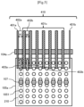
FIG. 7 illustrates the configuration of thestructure 202 including magnets andrib structures 601 in the third embodiment. This configuration is the same as that of the first embodiment in such a point that the space below the bottom surface of thestructure 202 including the magnets is partitioned for each reaction lane 210 (seeFIG. 2 ) by disposing therib structures 601 on the bottom surface of thestructure 202. - However, for
rib structures reaction lanes 210 at the left and right ends, a position the same as a front surface of thestructure 202 is set todistal end portions rib structures side rib structures 601c between therib structures distal end portions 6011c are set to a position closer to the dispensingmachines 107. - That is, the
distal end portions 6011c of the inner-side rib structures 601c protrude toward the side of the dispensingmachines 107 more than thedistal end portions rib structures - It is considered that, in a vicinity of a distal end of the dispensing
machine 107 close to the side of thesolution plates FIG. 2 ), the fine particles constituting the cross-contamination source are generated by influence of an airflow and the like during the test processing and the vicinity hence highly probably constitutes a scattering source. Thus, it is possible to exert the straightening effect for eachreaction lane 210 from an upstream side of the airflow by extending thedistal end portion 6011c to the vicinity of the dispensingmachine 107 as therib structure 601c. - Moreover, it is possible to form flow passages each of which causes an airflow in a lateral direction to flow toward the
reaction lanes 210 at the left and right ends as indicated by a direction of an arrow 402, by setting thedistal end portions structure 202 as in therib structures distal end portions rib structures 601 appropriate for eachreaction lane 210. - Moreover, it is possible to use such a mechanism as an actuator to dynamically change the positions of the
distal end portions rib structures 601a to 601c. By enabling the dynamic change in positions of thedistal end portions solution plates machines 107, and the like are automatically executed. - According to the present embodiment, in addition to the effects described in the first embodiment and the second embodiment, the straightening effect for each
reaction lane 210 can be exerted from the upstream side of the airflow on which the fine particles constituting the cross-contamination source are generated due to the influence of the airflow and the like during the test processing and which hence highly probably constitutes the scattering source. - A description is now given of a configuration according to a fourth embodiment of the present invention. The present embodiment focuses on the
exhaust opening 104a in a device rear portion in the first embodiment and more effectively straightens the airflow passing through the space formed by thestructure 202 and therib structures 203 described inFIG. 2 . -
FIG. 8 illustrates a configuration of therib structures 203 and a periphery of anexhaust opening 701 in the fourth embodiment and corresponds to a configuration of therib structures 203 and the periphery of theexhaust opening 104a as viewed from the cross section indicated by the arrows C-C illustrated inFIG. 1 in the first embodiment. The configurations of therib structures 203, thesolution plate 105a, and the dispensingmachines 107 inFIG. 8 are the same as those described in the first embodiment. - It is assumed that the
exhaust opening 701 in the present embodiment has a flow passage shape having an opening shape changing in a device left-right direction (left-right direction of the page) as openingregions FIG. 8 , the airflow which passes through areaction lane 702a at the left end substantially passes through theopening region 7011 having a wide flow passage area of theexhaust opening 701, and the airflow which passes through anadjacent reaction lane 702b substantially passes through theopening region 7012 having a narrow flow passage area of theexhaust opening 701. In general, the pressure loss is relatively large at both ends in the length direction of a rectangular pipeline, while the pressure loss is small in a vicinity of the center. Thus, achieving such a flow passage shape that the flow passage area is wide at both ends and the flow passage area is narrow at the center as 701, the pressure loss can be balanced. Therefore, it is possible to uniformize the flowrates of theairflow 703a passing through the lane at the left end and theairflow 703b passing through the adjacent lane, and hence, it is possible to carry, on the stabilized airflows, the fine particles that contain the sample and the like and that constitute the cross-contamination source, thereby more efficiently collecting the fine particles. - In
FIG. 8 , there is illustrated an example in which a flow passage cross sectional area of theexhaust opening 701 changes stepwise in the device left-right direction, but the flow passage cross sectional area may have any shape, and may have a flow passage cross sectional area distribution which changes continuously. Moreover, theexhaust opening 701 may be configured as a hole provided to thetop plate 103 for test (seeFIG. 1 ) as well as a duct formed of resin, metal, or the like. - Further, the
exhaust opening 701 may be configured such that an entire region thereof is formed at a width of theopening region 7011 and a member which increases an air resistance, for example, a mesh plate, may be installed in a portion corresponding to theopening region 7012. - With the configuration described above, according to the present embodiment, effects similar to those described in the first embodiment to the third embodiment can be obtained.
- A description is now given of a configuration according to a fifth embodiment of the present invention. The present embodiment is an example in which the
dispensing device 100 described in any one of the first embodiment to the fourth embodiment is applied to a genetic testing device (hereinafter referred to as a PCR device) 800 which uses the PCR reaction. Note that the dispensingdevices 100 described herein include the dispensing devices obtained by making the changes as described in the second embodiment to the fourth embodiment to thedispensing device 100 described in the first embodiment. -
FIG. 9 is a schematic configuration of thePCR device 800 which uses thedispensing device 100 in the fifth embodiment. ThePCR device 800 includes aDNA extraction unit 801 provided with thedispensing device 100, aDNA amplification unit 802, anamplicon detection unit 803, acontrol unit 810 which controls the entire device, and anoutput unit 820 which outputs a result of the test. - The
DNA extraction unit 801 executes mixing of a solution or the like containing a detection target such as a DNA or an RNA and a reagent, magnetic particles, and the like with each other, discharging/stirring, dispensing, and the like to extract the detection target. In theDNA extraction unit 801, the number of operations such as the discharging/stirring and the dispensing which use thedispensing device 100 and the movements and the like of the dispensing machines is large, a risk of the contamination is relatively high, and hence, the straightening structure of thereaction lanes 210 achieved by the dispensingdevices 100 described in the first embodiment to the fourth embodiment is particularly effective. - In the
DNA amplification unit 802, the solution containing the detection target such as a DNA or an RNA extracted by theDNA extraction unit 801 is dispensed and is placed in a device called a thermal cycler (not illustrated). The thermal cycler is a device which can execute high-speed and precise temperature adjustment, executes temperature adjustment according to the detection target or the reagent which is used, to execute such operations as denaturation, annealing, and extension, thereby amplifying a DNA or an RNA. - Moreover, in the
amplicon detection unit 803, a container containing the detection target such as a DNA or an RNA which is amplified by theDNA amplification unit 802 is dispensed, and fluorescence intensity and the like are measured, thereby quantitatively evaluating an amplification amount of the detection target. - As a result of the use of the
dispensing device 100 described in any one of the first embodiment to the fourth embodiment in thegenetic testing device 800 which uses the PCR reaction as described in the fifth embodiment, the risk of the cross contamination can be reduced, thereby being able to increase reliability of a genetic test result. - The description has been given of the invention made by the present inventors, on the basis of the embodiments, but the present invention is not limited to the embodiments, and it should be understood that the present invention can be modified in various ways within a scope not departing from the gist thereof. For example, the above-mentioned embodiments are detailed for an easy-to-understand description of the present invention, and the present invention is not necessarily limited to a case including all of the described configurations. Moreover, to a part of the configuration of each of the embodiments, another configuration can be added, the part can be deleted, or the part can be replaced by another configuration.
-
- 100: Dispensing device
- 101: Device cover
- 102: Intake opening
- 103: Top plate for test
- 104a, 104b, 104c, 701: Exhaust opening
- 105a, 105b: Solution plate
- 106: Dispensing device body
- 107: Dispensing machine
- 201a, 201b: Guide
- 202: Structure
- 203, 410, 501, 601: Rib structure
- 210: Reaction lane
- 800: Genetic testing device
Claims (8)
- A dispensing device comprising:a plurality of dispensing machines;a dispensing device body that has the plurality of dispensing machines mounted thereto and is capable of moving along a direction of a plurality of lanes of a solution plate including a plurality of containers each of which accommodates a reagent or a sample and that are integrally formed along the lanes;a top plate for test on which the dispensing device body and the solution plate are placed; anda device cover that covers the dispensing device body in combination with the top plate for test,wherein a plurality of ribs that separate a space above the plurality of lanes of the solution plate into spaces each for each lane of the plurality of lanes and cover the spaces are formed in the dispensing device body.
- The dispensing device according to claim 1,
wherein an intake opening is formed in the device cover, an exhaust opening is formed in the top plate for test, and the plurality of ribs are formed such that a part of air that flows from the intake opening into an inside of the device cover and flows out from the exhaust opening flows along spaces formed by the plurality of ribs. - The dispensing device according to claim 2,
wherein the plurality of ribs are formed such that resistances against the air flowing in a vicinity of a surface of the solution plate along the spaces formed by the plurality of ribs are different from one another according to positions of the plurality of ribs. - The dispensing device according to claim 3,
wherein intervals between the plurality of ribs that separate the space above the plurality of lanes of the solution plate into the spaces each for each lane of the plurality of lanes and cover the spaces are different from one another according to the position of each rib of the plurality of ribs. - The dispensing device according to claim 4,
wherein the interval of the ribs that are among the plurality of ribs and cover the space above the lane in an end portion among the plurality of lanes of the solution plate is formed in such a manner as to be wider than the interval of the ribs that are among the plurality of ribs and cover the space above the lane on an inner side of the lane in the end portion. - The dispensing device according to claim 1,
wherein the plurality of dispensing machines are mounted to the dispensing device body in correspondence to the plurality of lanes, and intervals of the plurality of ribs that separate the space above the plurality of lanes of the solution plate into the spaces each for each lane of the plurality of lanes and cover the spaces and the dispensing machine vary according to positions of the plurality of ribs. - The dispensing device according to claim 2,
wherein the exhaust opening of the top plate for test is formed in such a manner as to cross the plurality of lanes of the solution plate, and a vicinity to an end portion of the exhaust opening in a direction crossing the plurality of lanes of the solution plate is formed in such a manner as to be lower in resistance against the air passing through the exhaust opening than an inner side of the vicinity to the end portion. - A genetic testing device comprising:a DNA detection unit;a DNA amplification unit that amplifies a detection target detected by the DNA detection unit;an amplicon detection unit that quantitatively evaluates an amplification amount of the detection target amplified by the DNA amplification unit;a control unit that controls the DNA detection unit, the DNA amplification unit, and the amplicon detection unit; andan output unit that outputs a result of the quantitative evaluation of the amplification amount of the detection target performed by the amplicon detection unit,wherein the DNA detection unit includes a dispensing device that dispenses a solution containing the detection target and a reagent to a container,the dispensing device includesa plurality of dispensing machines,a dispensing device body that has the plurality of dispensing machines mounted thereto and is capable of moving along a direction of a plurality of lanes of a solution plate including a plurality of containers each of which accommodates a reagent or a sample and that are integrally formed along the plurality of lanes,a top plate for test on which the dispensing device body and the solution plate are placed, anda device cover that covers the dispensing device body in combination with the top plate for test, anda plurality of ribs that separate a space above the plurality of lanes of the solution plate into spaces each for each lane of the plurality of lanes and cover the spaces are formed in the dispensing device body.
Applications Claiming Priority (1)
| Application Number | Priority Date | Filing Date | Title |
|---|---|---|---|
| PCT/JP2022/031443 WO2024038603A1 (en) | 2022-08-19 | 2022-08-19 | Dispensing device, and genetic test device provided with same |
Publications (2)
| Publication Number | Publication Date |
|---|---|
| EP4575510A1 true EP4575510A1 (en) | 2025-06-25 |
| EP4575510A4 EP4575510A4 (en) | 2026-07-01 |
Family
ID=89941707
Family Applications (1)
| Application Number | Title | Priority Date | Filing Date |
|---|---|---|---|
| EP22955775.6A Pending EP4575510A4 (en) | 2022-08-19 | 2022-08-19 | Dispensing device and genetic testing device so that |
Country Status (7)
| Country | Link |
|---|---|
| US (1) | US20250277806A1 (en) |
| EP (1) | EP4575510A4 (en) |
| JP (1) | JP7724381B2 (en) |
| KR (1) | KR102979383B1 (en) |
| CN (1) | CN119053864A (en) |
| TW (1) | TWI872601B (en) |
| WO (1) | WO2024038603A1 (en) |
Families Citing this family (1)
| Publication number | Priority date | Publication date | Assignee | Title |
|---|---|---|---|---|
| KR20260063512A (en) | 2024-10-30 | 2026-05-07 | 주식회사 엘지에너지솔루션 | Top cap welding apparatus of cylindrical battery cell and top cap welding method of cylindrical battery cell using the same |
Family Cites Families (11)
| Publication number | Priority date | Publication date | Assignee | Title |
|---|---|---|---|---|
| JPS57143444A (en) | 1981-02-27 | 1982-09-04 | Nippon Steel Corp | Continuous heat treating furnace having convection type preheating zone |
| US5895631A (en) * | 1995-03-20 | 1999-04-20 | Precision System Science Co., Ltd. | Liquid processing method making use of pipette device and apparatus for same |
| JP4141384B2 (en) * | 2001-09-17 | 2008-08-27 | 株式会社日立製作所 | Sample processing apparatus and sample processing method |
| TWI415770B (en) | 2006-01-13 | 2013-11-21 | Universal Bio Research Co Ltd | Variable form dispensing tube, deformation type dispensing device and deformation type dispensing processing method |
| US8562920B2 (en) * | 2006-03-28 | 2013-10-22 | Universal Bio Research Co., Ltd. | Micro plate treating device and micro plate treating method |
| KR20130029128A (en) * | 2010-07-23 | 2013-03-21 | 베크만 컬터, 인코포레이티드 | Vessel for real time pcr |
| JP2013134069A (en) * | 2011-12-26 | 2013-07-08 | Hitachi High-Technologies Corp | Automatic analyzer |
| TWI481446B (en) * | 2012-09-17 | 2015-04-21 | Univ Nat Taiwan | Digital microfluidic manipulation device and control method |
| AU2016253147B2 (en) * | 2015-04-24 | 2021-07-22 | Mesa Biotech, Inc. | Fluidic test cassette |
| WO2022003915A1 (en) * | 2020-07-02 | 2022-01-06 | 株式会社日立ハイテク | Cassette stand, reaction unit and genetic testing device |
| US11577513B2 (en) * | 2020-10-06 | 2023-02-14 | Funai Electric Co., Ltd. | Photoimageable nozzle member for reduced fluid cross-contamination and method therefor |
-
2022
- 2022-08-19 EP EP22955775.6A patent/EP4575510A4/en active Pending
- 2022-08-19 WO PCT/JP2022/031443 patent/WO2024038603A1/en not_active Ceased
- 2022-08-19 US US18/859,385 patent/US20250277806A1/en active Pending
- 2022-08-19 CN CN202280094807.9A patent/CN119053864A/en active Pending
- 2022-08-19 JP JP2024541395A patent/JP7724381B2/en active Active
- 2022-08-19 KR KR1020247031967A patent/KR102979383B1/en active Active
-
2023
- 2023-07-11 TW TW112125793A patent/TWI872601B/en active
Also Published As
| Publication number | Publication date |
|---|---|
| CN119053864A (en) | 2024-11-29 |
| KR20240151236A (en) | 2024-10-17 |
| US20250277806A1 (en) | 2025-09-04 |
| KR102979383B1 (en) | 2026-06-19 |
| TW202408661A (en) | 2024-03-01 |
| WO2024038603A1 (en) | 2024-02-22 |
| TWI872601B (en) | 2025-02-11 |
| EP4575510A4 (en) | 2026-07-01 |
| JP7724381B2 (en) | 2025-08-15 |
| JPWO2024038603A1 (en) | 2024-02-22 |
Similar Documents
| Publication | Publication Date | Title |
|---|---|---|
| EP3264102B1 (en) | Automatic analysis apparatus | |
| EP1470427B1 (en) | Low volume, non-contact liquid dispensing method | |
| EP2058664B1 (en) | Apparatus and method for handling fluids for analysis | |
| US12320820B2 (en) | Sample pretreatment device, analysis system including the device, and autosampler | |
| CN111604098B (en) | Micro-fluidic chip with side sample adding function | |
| EP1839756A1 (en) | Apparatus for separating magnetic particles from liquids containing said particles, and an array of vessels suitable for use with such an apparatus | |
| US20250277806A1 (en) | Dispensing Device and Genetic Testing Device Provided Therewith | |
| EP0408147A2 (en) | Evaporation covers | |
| US9795967B2 (en) | Sample analyzer and reagent container | |
| US20050281707A1 (en) | Clinical specimen processing apparatus and clinical specimen processing system | |
| US8840851B2 (en) | Pipette tip supplying apparatus, sample analyzer and pipette tip supplying method | |
| EP3992636B1 (en) | Automated analyzer | |
| CN103175977A (en) | Automatic analyzing device | |
| JPWO2007111347A1 (en) | Microplate processing apparatus and microplate processing method | |
| EP3677918A1 (en) | Digital dispense system | |
| US20220126285A1 (en) | Fluid delivery device and method for carrying out chemical or biological assays | |
| JP7458882B2 (en) | Automatic analyzer, dispensing device and dispensing control method | |
| WO2018190336A1 (en) | Liquid delivery device and liquid delivery method | |
| EP3950134A1 (en) | Specimen container and cap | |
| US20230219088A1 (en) | Nucleic acid analyzer | |
| JPH10293089A (en) | Dispensing device | |
| US12222361B2 (en) | Method for dispensing a liquid sample by means of a dispensing apparatus | |
| EP4235187A1 (en) | Automatic analysis device | |
| EP4592688A1 (en) | Automated analysis device | |
| WO2015152296A1 (en) | Pinch valve and automatic analysis device provided with pinch valve |
Legal Events
| Date | Code | Title | Description |
|---|---|---|---|
| STAA | Information on the status of an ep patent application or granted ep patent |
Free format text: STATUS: THE INTERNATIONAL PUBLICATION HAS BEEN MADE |
|
| PUAI | Public reference made under article 153(3) epc to a published international application that has entered the european phase |
Free format text: ORIGINAL CODE: 0009012 |
|
| STAA | Information on the status of an ep patent application or granted ep patent |
Free format text: STATUS: REQUEST FOR EXAMINATION WAS MADE |
|
| 17P | Request for examination filed |
Effective date: 20241018 |
|
| AK | Designated contracting states |
Kind code of ref document: A1 Designated state(s): AL AT BE BG CH CY CZ DE DK EE ES FI FR GB GR HR HU IE IS IT LI LT LU LV MC MK MT NL NO PL PT RO RS SE SI SK SM TR |
|
| DAV | Request for validation of the european patent (deleted) | ||
| DAX | Request for extension of the european patent (deleted) | ||
| A4 | Supplementary search report drawn up and despatched |
Effective date: 20260529 |
|
| RIC1 | Information provided on ipc code assigned before grant |
Ipc: G01N 35/10 20060101AFI20260522BHEP Ipc: G01N 1/00 20060101ALI20260522BHEP Ipc: B01L 7/00 20060101ALI20260522BHEP Ipc: C12Q 1/686 20180101ALI20260522BHEP |