EP4575415A1 - Verteiltes erfassungssystem mit kohärenter detektion - Google Patents
Verteiltes erfassungssystem mit kohärenter detektion Download PDFInfo
- Publication number
- EP4575415A1 EP4575415A1 EP23218873.0A EP23218873A EP4575415A1 EP 4575415 A1 EP4575415 A1 EP 4575415A1 EP 23218873 A EP23218873 A EP 23218873A EP 4575415 A1 EP4575415 A1 EP 4575415A1
- Authority
- EP
- European Patent Office
- Prior art keywords
- radiation
- light
- fibre
- light combining
- combining system
- Prior art date
- Legal status (The legal status is an assumption and is not a legal conclusion. Google has not performed a legal analysis and makes no representation as to the accuracy of the status listed.)
- Pending
Links
Images


Classifications
-
- G—PHYSICS
- G01—MEASURING; TESTING
- G01D—MEASURING NOT SPECIALLY ADAPTED FOR A SPECIFIC VARIABLE; ARRANGEMENTS FOR MEASURING TWO OR MORE VARIABLES NOT COVERED IN A SINGLE OTHER SUBCLASS; TARIFF METERING APPARATUS; MEASURING OR TESTING NOT OTHERWISE PROVIDED FOR
- G01D5/00—Mechanical means for transferring the output of a sensing member; Means for converting the output of a sensing member to another variable where the form or nature of the sensing member does not constrain the means for converting; Transducers not specially adapted for a specific variable
- G01D5/26—Mechanical means for transferring the output of a sensing member; Means for converting the output of a sensing member to another variable where the form or nature of the sensing member does not constrain the means for converting; Transducers not specially adapted for a specific variable characterised by optical transfer means, i.e. using infrared, visible, or ultraviolet light
- G01D5/32—Mechanical means for transferring the output of a sensing member; Means for converting the output of a sensing member to another variable where the form or nature of the sensing member does not constrain the means for converting; Transducers not specially adapted for a specific variable characterised by optical transfer means, i.e. using infrared, visible, or ultraviolet light with attenuation or whole or partial obturation of beams of light
- G01D5/34—Mechanical means for transferring the output of a sensing member; Means for converting the output of a sensing member to another variable where the form or nature of the sensing member does not constrain the means for converting; Transducers not specially adapted for a specific variable characterised by optical transfer means, i.e. using infrared, visible, or ultraviolet light with attenuation or whole or partial obturation of beams of light the beams of light being detected by photocells
- G01D5/353—Mechanical means for transferring the output of a sensing member; Means for converting the output of a sensing member to another variable where the form or nature of the sensing member does not constrain the means for converting; Transducers not specially adapted for a specific variable characterised by optical transfer means, i.e. using infrared, visible, or ultraviolet light with attenuation or whole or partial obturation of beams of light the beams of light being detected by photocells influencing the transmission properties of an optical fibre
- G01D5/35338—Mechanical means for transferring the output of a sensing member; Means for converting the output of a sensing member to another variable where the form or nature of the sensing member does not constrain the means for converting; Transducers not specially adapted for a specific variable characterised by optical transfer means, i.e. using infrared, visible, or ultraviolet light with attenuation or whole or partial obturation of beams of light the beams of light being detected by photocells influencing the transmission properties of an optical fibre using other arrangements than interferometer arrangements
- G01D5/35354—Sensor working in reflection
- G01D5/35358—Sensor working in reflection using backscattering to detect the measured quantity
-
- G—PHYSICS
- G01—MEASURING; TESTING
- G01D—MEASURING NOT SPECIALLY ADAPTED FOR A SPECIFIC VARIABLE; ARRANGEMENTS FOR MEASURING TWO OR MORE VARIABLES NOT COVERED IN A SINGLE OTHER SUBCLASS; TARIFF METERING APPARATUS; MEASURING OR TESTING NOT OTHERWISE PROVIDED FOR
- G01D5/00—Mechanical means for transferring the output of a sensing member; Means for converting the output of a sensing member to another variable where the form or nature of the sensing member does not constrain the means for converting; Transducers not specially adapted for a specific variable
- G01D5/26—Mechanical means for transferring the output of a sensing member; Means for converting the output of a sensing member to another variable where the form or nature of the sensing member does not constrain the means for converting; Transducers not specially adapted for a specific variable characterised by optical transfer means, i.e. using infrared, visible, or ultraviolet light
- G01D5/32—Mechanical means for transferring the output of a sensing member; Means for converting the output of a sensing member to another variable where the form or nature of the sensing member does not constrain the means for converting; Transducers not specially adapted for a specific variable characterised by optical transfer means, i.e. using infrared, visible, or ultraviolet light with attenuation or whole or partial obturation of beams of light
- G01D5/34—Mechanical means for transferring the output of a sensing member; Means for converting the output of a sensing member to another variable where the form or nature of the sensing member does not constrain the means for converting; Transducers not specially adapted for a specific variable characterised by optical transfer means, i.e. using infrared, visible, or ultraviolet light with attenuation or whole or partial obturation of beams of light the beams of light being detected by photocells
- G01D5/353—Mechanical means for transferring the output of a sensing member; Means for converting the output of a sensing member to another variable where the form or nature of the sensing member does not constrain the means for converting; Transducers not specially adapted for a specific variable characterised by optical transfer means, i.e. using infrared, visible, or ultraviolet light with attenuation or whole or partial obturation of beams of light the beams of light being detected by photocells influencing the transmission properties of an optical fibre
- G01D5/35338—Mechanical means for transferring the output of a sensing member; Means for converting the output of a sensing member to another variable where the form or nature of the sensing member does not constrain the means for converting; Transducers not specially adapted for a specific variable characterised by optical transfer means, i.e. using infrared, visible, or ultraviolet light with attenuation or whole or partial obturation of beams of light the beams of light being detected by photocells influencing the transmission properties of an optical fibre using other arrangements than interferometer arrangements
- G01D5/35354—Sensor working in reflection
- G01D5/35358—Sensor working in reflection using backscattering to detect the measured quantity
- G01D5/35361—Sensor working in reflection using backscattering to detect the measured quantity using elastic backscattering to detect the measured quantity, e.g. using Rayleigh backscattering
-
- G—PHYSICS
- G01—MEASURING; TESTING
- G01D—MEASURING NOT SPECIALLY ADAPTED FOR A SPECIFIC VARIABLE; ARRANGEMENTS FOR MEASURING TWO OR MORE VARIABLES NOT COVERED IN A SINGLE OTHER SUBCLASS; TARIFF METERING APPARATUS; MEASURING OR TESTING NOT OTHERWISE PROVIDED FOR
- G01D5/00—Mechanical means for transferring the output of a sensing member; Means for converting the output of a sensing member to another variable where the form or nature of the sensing member does not constrain the means for converting; Transducers not specially adapted for a specific variable
- G01D5/26—Mechanical means for transferring the output of a sensing member; Means for converting the output of a sensing member to another variable where the form or nature of the sensing member does not constrain the means for converting; Transducers not specially adapted for a specific variable characterised by optical transfer means, i.e. using infrared, visible, or ultraviolet light
- G01D5/32—Mechanical means for transferring the output of a sensing member; Means for converting the output of a sensing member to another variable where the form or nature of the sensing member does not constrain the means for converting; Transducers not specially adapted for a specific variable characterised by optical transfer means, i.e. using infrared, visible, or ultraviolet light with attenuation or whole or partial obturation of beams of light
- G01D5/34—Mechanical means for transferring the output of a sensing member; Means for converting the output of a sensing member to another variable where the form or nature of the sensing member does not constrain the means for converting; Transducers not specially adapted for a specific variable characterised by optical transfer means, i.e. using infrared, visible, or ultraviolet light with attenuation or whole or partial obturation of beams of light the beams of light being detected by photocells
- G01D5/344—Mechanical means for transferring the output of a sensing member; Means for converting the output of a sensing member to another variable where the form or nature of the sensing member does not constrain the means for converting; Transducers not specially adapted for a specific variable characterised by optical transfer means, i.e. using infrared, visible, or ultraviolet light with attenuation or whole or partial obturation of beams of light the beams of light being detected by photocells using polarisation
-
- G—PHYSICS
- G01—MEASURING; TESTING
- G01D—MEASURING NOT SPECIALLY ADAPTED FOR A SPECIFIC VARIABLE; ARRANGEMENTS FOR MEASURING TWO OR MORE VARIABLES NOT COVERED IN A SINGLE OTHER SUBCLASS; TARIFF METERING APPARATUS; MEASURING OR TESTING NOT OTHERWISE PROVIDED FOR
- G01D5/00—Mechanical means for transferring the output of a sensing member; Means for converting the output of a sensing member to another variable where the form or nature of the sensing member does not constrain the means for converting; Transducers not specially adapted for a specific variable
- G01D5/26—Mechanical means for transferring the output of a sensing member; Means for converting the output of a sensing member to another variable where the form or nature of the sensing member does not constrain the means for converting; Transducers not specially adapted for a specific variable characterised by optical transfer means, i.e. using infrared, visible, or ultraviolet light
- G01D5/32—Mechanical means for transferring the output of a sensing member; Means for converting the output of a sensing member to another variable where the form or nature of the sensing member does not constrain the means for converting; Transducers not specially adapted for a specific variable characterised by optical transfer means, i.e. using infrared, visible, or ultraviolet light with attenuation or whole or partial obturation of beams of light
- G01D5/34—Mechanical means for transferring the output of a sensing member; Means for converting the output of a sensing member to another variable where the form or nature of the sensing member does not constrain the means for converting; Transducers not specially adapted for a specific variable characterised by optical transfer means, i.e. using infrared, visible, or ultraviolet light with attenuation or whole or partial obturation of beams of light the beams of light being detected by photocells
- G01D5/353—Mechanical means for transferring the output of a sensing member; Means for converting the output of a sensing member to another variable where the form or nature of the sensing member does not constrain the means for converting; Transducers not specially adapted for a specific variable characterised by optical transfer means, i.e. using infrared, visible, or ultraviolet light with attenuation or whole or partial obturation of beams of light the beams of light being detected by photocells influencing the transmission properties of an optical fibre
- G01D5/35306—Mechanical means for transferring the output of a sensing member; Means for converting the output of a sensing member to another variable where the form or nature of the sensing member does not constrain the means for converting; Transducers not specially adapted for a specific variable characterised by optical transfer means, i.e. using infrared, visible, or ultraviolet light with attenuation or whole or partial obturation of beams of light the beams of light being detected by photocells influencing the transmission properties of an optical fibre using an interferometer arrangement
-
- G—PHYSICS
- G01—MEASURING; TESTING
- G01D—MEASURING NOT SPECIALLY ADAPTED FOR A SPECIFIC VARIABLE; ARRANGEMENTS FOR MEASURING TWO OR MORE VARIABLES NOT COVERED IN A SINGLE OTHER SUBCLASS; TARIFF METERING APPARATUS; MEASURING OR TESTING NOT OTHERWISE PROVIDED FOR
- G01D5/00—Mechanical means for transferring the output of a sensing member; Means for converting the output of a sensing member to another variable where the form or nature of the sensing member does not constrain the means for converting; Transducers not specially adapted for a specific variable
- G01D5/26—Mechanical means for transferring the output of a sensing member; Means for converting the output of a sensing member to another variable where the form or nature of the sensing member does not constrain the means for converting; Transducers not specially adapted for a specific variable characterised by optical transfer means, i.e. using infrared, visible, or ultraviolet light
- G01D5/32—Mechanical means for transferring the output of a sensing member; Means for converting the output of a sensing member to another variable where the form or nature of the sensing member does not constrain the means for converting; Transducers not specially adapted for a specific variable characterised by optical transfer means, i.e. using infrared, visible, or ultraviolet light with attenuation or whole or partial obturation of beams of light
- G01D5/34—Mechanical means for transferring the output of a sensing member; Means for converting the output of a sensing member to another variable where the form or nature of the sensing member does not constrain the means for converting; Transducers not specially adapted for a specific variable characterised by optical transfer means, i.e. using infrared, visible, or ultraviolet light with attenuation or whole or partial obturation of beams of light the beams of light being detected by photocells
- G01D5/353—Mechanical means for transferring the output of a sensing member; Means for converting the output of a sensing member to another variable where the form or nature of the sensing member does not constrain the means for converting; Transducers not specially adapted for a specific variable characterised by optical transfer means, i.e. using infrared, visible, or ultraviolet light with attenuation or whole or partial obturation of beams of light the beams of light being detected by photocells influencing the transmission properties of an optical fibre
- G01D5/35338—Mechanical means for transferring the output of a sensing member; Means for converting the output of a sensing member to another variable where the form or nature of the sensing member does not constrain the means for converting; Transducers not specially adapted for a specific variable characterised by optical transfer means, i.e. using infrared, visible, or ultraviolet light with attenuation or whole or partial obturation of beams of light the beams of light being detected by photocells influencing the transmission properties of an optical fibre using other arrangements than interferometer arrangements
- G01D5/35354—Sensor working in reflection
- G01D5/35358—Sensor working in reflection using backscattering to detect the measured quantity
- G01D5/35364—Sensor working in reflection using backscattering to detect the measured quantity using inelastic backscattering to detect the measured quantity, e.g. using Brillouin or Raman backscattering
Definitions
- the present invention relates to a distributed sensing system and a respective method of performing distributed sensing, wherein coherent detection is provided.
- the present invention relates to a distributed acoustic sensing system and a distributed temperature sensing system and a distributed strain sensing system each providing coherent detection.
- the present invention relates to multi-channel distributed sensing systems providing coherent detection.
- US 11,469,816 B2 discloses a distributed sensing apparatus based on optical time domain reflectometry (OTDR).
- An optical splitter being in optical communication with an optical source has first and second outputs, a sensing fibre being in optical communication with the first output of the optical splitter.
- a combining unit combines a reference signal derived from the second output of the optical splitter with a backscattered signal derived from the sensing fibre.
- the combining unit comprises one or more 3x3 fused fibre couplers.
- the combining unit comprises a polarisation diversity arrangement and is configured to align, in the combining unit, the polarisation of a first signal derived from the backscattered signal with that of a first signal derived from the reference signal which is derived from the second output of the optical splitter.
- polarisation of a second signal derived from the backscattered signal with that of a second signal derived from the reference signal is aligned.
- this document utilizes a separate polarisation beam splitter which receives the reference signal from the optical splitter.
- the patent EP 2 816 323 B1 discloses polarisation-diverse coherent detection for distributed acoustic sensing analysing acoustic pressure.
- a distributed sensing system comprises a light source, in particular laser source, for providing a primary radiation; a primary radiation splitter arranged to receive the primary radiation at an input port and provide at least one injection radiation, a first reference radiation and a second reference radiation at at least three output ports; one or more optical fibres arrangeable to receive a respective fibre input radiation portion which is derived from the injection radiation; a light combining system configured, in particular for every one of the one or more optical fibres, to receive backscatter light returned from the one or more optical fibres, or light derived from the backscatter light, to receive the first reference radiation or light derived from the first reference radiation, and in particular to receive the second reference radiation or light derived from the second reference radiation, as light combining system radiation inputs and provide one or more light combining system radiation outputs based on the light combining system radiation inputs; a detection system configured to detect the one or more light combining system radiation outputs, thereby providing coherent
- the light source may provide and/or generate coherent electromagnetic radiation, for example having a coherence length between 10 m and more than 100 km.
- the primary radiation may consist or comprise light in the near-infrared spectral region or in the visible optical region.
- the primary radiation may or may not have a defined polarisation state.
- the light source may be configured to provide primary radiation having adjustable wavelength/frequency and/or adjustable polarisation state.
- the light source may generate or provide primary radiation having substantially constant wavelength not changing with time, stepped wavelengths or a continuously variable (chirped) wavelength. (For performing distributed temperature sensing, the light source may be configured to provide primary radiation which may have different adjustable wavelengths depending on the circumstances or requirements.)
- the primary radiation splitter may be in optical communication with the light source by an optical fibre or optical waveguide and/or by free space optical paths.
- the primary radiation splitter may receive light which is based on the primary radiation.
- Optional optical components may for example include collimation optics, and/or isolator and/or filter and/or an optical fibre.
- the primary radiation splitter may be or may consist of one or more only one optical device or components, for example optical elements or devices which are in optical communication with each other by for example intermediate optical fibres or free space optical paths.
- the primary radiation splitter may or may not be a hybrid system comprising solid components and free space radiation paths.
- the fused fibre coupler For manufacturing the fused fibre coupler, at least three fibres may be partially uncoated, heated above the softening point and/or twisted and/or stretched and/or connected or fused together, cooled down and/or recoated. In the fused region, interaction of radiation with the different cores leads to a transfer of radiation between cores. Length of the interaction region and distance of cores may be adjusted to achieve the desired power rations in the output fibers.
- the primary radiation splitter may be a fused fibre optic coupler or may be configured as a fused fibre optic coupler, for example providing the splitting functionality by a single fused optical structure.
- the primary radiation splitter may have even or uneven splitting characteristics or splitting ratio which may be adjusted or selected depending on the application.
- the relative light powers of the at least one injection radiation, the first reference radiation and the second reference radiation may be different or may be equal.
- the respective power ratios for the different output radiations may be adjusted such that a desired or demanded launch pulse power (power levels downstream the modulator which may contain an amplifier) or power of the fibre input radiation is injected into the one or more optical fibres, for example in order to achieve a satisfactory or optimum signal-to-noise performance and/or a desired or demanded light power into the modulator, For example, to achieve optimum modulation and/or amplification.
- the one or more optical fibres may be in direct or indirect optical communication with the primary radiation splitter, in particular the output port which outputs the injection radiation.
- the respective fibre input radiation portion may be derived from the injection radiation by for example passing through a modulator and/or passing through one or more further radiation splitters being for example arranged between the primary radiation splitter and the respective modulator or between the modulator and the respective optical fibre.
- the light combining system may enable to provide coherent detection by the detection system.
- the distributed sensing system may be configured to provide coherent detection with or without polarisation-diverse detection for one or plural optical fibres.
- the backscatter light may include Rayleigh backscatter light and/or Brillouin backscatter light and/or Raman backscatter light which may be generated within the respective optical fibre due to the injection of the respective fibre input radiation portion.
- the backscatter light may be dependent on a (temporal change of) a refractive index of the optical fibre which may in turn be dependent on strain, acoustic disturbance and/or temperature of the optical fibre.
- the backscatter light may then optionally be split or divided with respect to its polarisation state, in order for example to obtain light which is derived from the backscatter light.
- the light combining system may be configured, in particular for every one of the one or more optical fibres, to receive light which is based on the backscatter light returned from the respective optical fibre.
- the light combining system may receive light which is based on the first reference radiation and also light which is based on the second reference radiation.
- one or more further light splitting or dividing elements may be arranged between the primary radiation splitter and the light combining system.
- no other optical element or splitting device may be arranged between the primary radiation splitter and the light combining system.
- the light combining system may comprise one or more optical components which may be configured to combine at least two light portions and/or which are configured to provide or achieve splitting or dividing the combined lights, depending on the application, as will be described in more detail below.
- the light combining system may comprise four input ports and two, four or six output ports, depending on the manner of detection.
- the light combining system may comprise eight input ports, and four or eight or twelve output ports.
- the light combining system may comprise 2xN input ports and N or 2N or 3N output ports.
- the detection system may comprise one or more radiation light or backscatter light sensitive devices or elements, such as photo diodes.
- the detection system may be configured to detect (an intensity of) the one or more light combining system radiation outputs separately.
- coherent detection in particular polarisation-diverse coherent detection, for one or more optical fibres may be provided in a simple and non-complex implementation.
- the distributed sensing system may in particular be configured to switch between a coherent non-polarisation diverse detection to a coherent polarisation-diverse detection.
- the system may be configured to provide polarisation-diverse coherent detection for zero or one or more of the one or more optical fibres and may be configured to provide non-polarisation-diverse coherent detection for the remaining of the one or more optical fibres. Thereby, flexibility may be increased depending for example on monitoring requirements.
- the distributed sensing system may be configured to perform optical time domain reflectometry (OTDR) or coherent optical time domain reflectrometry (COTDR). According to other embodiments, the distributed sensing system may be configured to provide a Brillouin optical time domain analyzer (BOTDA) or optical frequency domain reflectrometry (OFDR). Or it may be configured for fiber bragg gratings (FBG) or other reflector sources in the fibre.
- OTDR optical time domain reflectometry
- COTDR coherent optical time domain reflectrometry
- BOTDA Brillouin optical time domain analyzer
- OFDR optical frequency domain reflectrometry
- FBG fiber bragg gratings
- the light source may be fibre-coupled to downstream elements.
- the at least one injection radiation may, in particular using a modulator, be modulated in amplitude and/or frequency and/or phase and/or polarization and then a respective fibre input radiation portion may be injected into the respective sensing optical fibre. Due to light-matter interactions in the optical fibre backscatter signals or backscatter light may evolve. Due to the environment at different locations of the optical fibre properties of the backscatter may change.
- the distributed sensing system may detect the one or more light combining system radiation outputs in a time resolved manner enabling, due to time-of-flight considerations, to provide location sensitive or spatially resolved distributed sensing.
- the frequency-dependend response of the fibre may be converted into time-domain using Fourier transformation.
- the power level for each photodetector may depend on the maximum current load of the receivers and the power level required to minimize signal noise, for example power levels in the range of less than 1 to 5 mW may be used for each detector.
- the primary radiation splitter may be configured or comprise a 1xN or 1xM coupler, for example to create more local oscillator signals for multi-fibre channel schemes or for multiple pulse generation sections that create different pulse configuration for different sensing fibres.
- the DFOS may use for example a single laser source and a coherent detection scheme where multiple backscatter signals are mixed with multiple local oscillator signals (reference radiation signals).
- Plural backscatter signals can be created by multiple sensor fibres and/or by polarisation splitting for polarisation-diverse detection.
- the coherent detection can be homodyne, i.e., without intermediate frequency (IF) between backscattering and local oscillator or heterodyne, i.e., with intermediate frequency.
- Mixing and detection of backscatter and local oscillator can be performed using 2x1 couplers, 2x2 couplers, 2x3 couplers, 3x3 couplers, single photo diodes or balanced photo diodes.
- 1x2 couplers or 2x3 couplers may be implemented with 2x2 or 3x3 couplers, respectively, where one input port (or fibre) or one output port (or fibre) it not provided or not used.
- Embodiments of the present invention provide a distributed acoustic sensing (DAS) and/or Brillouin optical time domain reflectometry (BOTDR).
- DAS distributed acoustic sensing
- BOTDR Brillouin optical time domain reflectometry
- one laser source may be utilized and optionally an additional component (e.g., AOM) may create a frequency shift between backscattering and local oscillator (intermediate frequency for heterodyne coherent detection).
- the distributed sensing system further comprises in particular for at least one or for every one of the one or more optical fibres: a respective polarisation splitting device arranged to receive the backscatter light from the respective fibre and to provide at least a first polarisation component and a second polarisation component of the respective backscatter light at outputs for light combining system radiation inputs.
- the polarisation splitting device (in particular for every one of the one or more optical fibres) may not be comprised in the light combining system but may be a respective component outside the combining system but which may provide input to the light combining system.
- the first and second polarisation components of the backscatter light may for example be polarisation components being perpendicular to each other.
- the polarisation splitting device may provide more than two polarisation components, such as three, four, five or even a higher number of different polarisation components, depending on the application.
- the polarisation splitting device may substantially be configured as a fibre-optic polarisation beam splitter.
- a polarisation beam splitter may be considered as a single optical component (e.g. including optically anisotropic material, e.g. birefringent (or birefractive) material) which performs the splitting of input radiation to at least to output radiation portions which are differently polarized, in particular having polarisation directions being substantially perpendicular to each other.
- PBS polarisation beam splitter
- the polarisation splitting device may comprise one or more components or units, for example a unit which merely splits the light (in two or more portions) and one or more components which only polarizes light portions for example output by the splitting element.
- the light combining system thereby receives four input radiation portions.
- the first and the second polarisation component of the respective backscatter light may thereby be output by the polarisation splitting device which is associated or provided for the respective optical sensing fibre.
- the system further comprises at least one modulator configured to receive one of the at least one injection radiation and provide fibre input radiation, the modulator in particular being configured to modulate the injection radiation with respect to amplitude and/or frequency and/or phase and/or forming a pulse pattern and/or forming temporary intensity and/or phase and/or frequency and/or polarisation profile, in order to obtain the fibre input radiation, wherein for at least one or for every fibre the respective fibre input radiation portion is derived from the fibre input radiation.
- only one modulator may be provided which provides fibre input radiation from which the respective fibre input radiation portion for each of the one or more optical fibres is derived.
- Embodiments of the present invention also support that more than one modulator is present which potentially provides differently modulated fibre input radiation (e.g. including pulse patterns having different characteristic) for different groups or different sets of optical sensing fibres.
- the fibre input radiation portions for the particular one or more optical fibres may be designed and configured as required by the particular application.
- the sensing system further comprises in particular in case the system comprises plural optical fibres: a fibre input radiation splitter, in particular 1xN splitter for N fibres, configured to receive the fibre input radiation and to output for the plural optical fibres a respective fibre input radiation portion.
- a fibre input radiation splitter in particular 1xN splitter for N fibres, configured to receive the fibre input radiation and to output for the plural optical fibres a respective fibre input radiation portion.
- the fibre input radiation splitter may be configured as a single optical device (e.g. fused fibre coupler) or unit or comprise different components, for example splitters in a cascade, depending on the application. Thereby multi-channel distributed sensing may be enabled. In case more than one modulator is provided, downstream each of the modulators, an associated fibre input radiation splitter may be arranged, such that the distributed sensing system may comprise plural fibre input radiation splitters, for example arranged downstream the one or more modulators.
- the primary radiation splitter may be configured as required by the application and depending on whether polarisation-diverse detection is required or not.
- a 1xM coupler e.g. fused 1xM fibre coupler
- a commercially available optical element can be utilized for implementation and furthermore manufacturing costs may be reduced and complexity may be reduced.
- optical losses may be reduced using a 1 ⁇ M coupler where M ⁇ 3 compared to conventionally utilized splitting arrangements.
- the system further comprises one or more further primary radiation splitters, in particular 1x2 splitters (e.g. fused couplers), arranged downstream or upstream the primary radiation splitter in one or more stages or in a cascade receiving input from or providing input to the primary radiation splitter, thereby providing a primary radiation splitting system having as many output ports in order to provide for every fibre one reference radiation portion or a first reference radiation portion and a second reference radiation portion as light combining system radiation inputs.
- 1x2 splitters e.g. fused couplers
- the number of radiation portions which are output may be adapted depending on the application and in particular thereby more optical sensing fibres may be supported.
- the light combining system is configured, for every one of plural optical fibres for which a first reference radiation portion and a second reference radiation portion are provided: to receive the first polarisation component of the respective backscatter light and the first reference radiation portion, and provide a first light combining system radiation output based on the first polarisation component and the first reference radiation portion; to receive the second polarisation component of the respective backscatter light and the second reference radiation portion, and provide a second light combining system radiation output based on the second polarisation component and the second reference radiation portion; wherein the detection system is configured to detect the first light combining system radiation output and the second light combining system radiation output separately.
- polarisation-diverse coherent detection is enabled for one or more optical fibres.
- more than two different polarisation components may be interfered or combined with respective reference radiation portions and separately detected, in particular for every one or a subgroup of the optical sensing fibres.
- the light combining system is configured, for every one of plural optical fibres for which one reference radiation portion but not two reference radiation portions are provided: to receive the respective backscatter light and the reference radiation portion, and provide the one mixing output radiation based on the respective backscatter light and the reference radiation portion; wherein the detection system is configured to detect the one mixing output radiation.
- non-polarisation-diverse coherent detection is provided or enabled for one or more optical sensing fibres.
- the one and/or the first and/or the second light combining system radiation output comprises: one or more (light combining system radiation output) components, in particular one, two or three components shifted in phase, which are detected separately, wherein for each component a light sensitive element is provided, in particular a photo diode.
- the respective light combining system radiation output(s) comprise one or more components, for example being different in phase or shifted in phase
- efficient denoising and/or phase demodulation may be performed.
- the signals may be shifted in phase by 120° (180°) with respect to each other.
- the system further comprises in particular for every of the one or more optical fibres: a fibre associated circulator, arranged in an injection radiation path between the modulator and the respective fibre; and/or arranged in a detection radiation path between the polarisation splitting device or the light combining system and the respective fibre.
- the respective circulator may provide particular or distinctive optical communication between different input/output ports.
- the respective circulator may enable proper injection of the fibre input radiation portion into the fibre and may enable to guide the respective backscatter light to the light combining system and/or to the respective polarisation splitting device.
- the circulator is configured: to pass the respective fibre input radiation portion, which is in particular output from at least one modulator or a splitter downstream the modulator, to the respective fibre; and/or to pass the respective backscatter light returned from the respective fibre to the respective polarisation splitting device or to the light combining system.
- the circulator may in particular prohibit to pass the respective fibre input radiation portion to the combining system or the respective polarisation splitting device. Further, the circulator may be configured to prohibit to pass the backscatter light returning from the optical fibre to the modulator or the primary radiation splitter. Thereby, an injection path and a detection path may properly be defined and separated from each other reducing disturbance.
- the light combining device may either be a fused fibre optic coupler or may be implemented as an optical hybrid including more optical elements or photonics on chip, photonics integrated circuits (PIC), or including in and out coupling or light splitting with free beam optics.
- PIC photonics integrated circuits
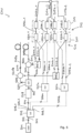
- the system 100 further comprises one or more optical fibres (collectively labelled with reference sign 109), which may be arranged close to an object to be monitored, wherein the illustrated embodiment comprises the optical fibre 109a.
- the one or more optical fibres 109 may be arranged close to or in proximity to one or more objects (such as a pipe, a cable, not illustrated) to be monitored for acoustic disturbance and/or temperature and/or strain.
- the optical fibres 109 may for example have a length of between 5 km and 50 km or more than 100 km.
- the system 100 further comprises a light combining system 110 which is configured to receive backscatter light 111 or light 111_1, 111_2 which is derived from the backscatter light 111 which returns from the optical fibre 109a.
- the combining system 110 is further configured and arranged to receive the first reference radiation 106_1 and in particular also the second reference radiation 106_2 as light combining system radiation inputs 112 and provide one or more light combining system radiation outputs 113 based on the light combining system radiation inputs 112.
- the system 100 further comprises a detection system 114 which is configured to detect the one or more light combining system radiation outputs 113.
- the embodiment illustrated in Fig. 1 provides polarisation-diverse coherent detection for at least one sensing fibre 109a. Therefore, the embodiment 100 illustrated in Fig. 1 further comprises (in particular for every one of the one or more optical fibres 109) a respective polarisation splitting device 115, in particular for the optical fibre 109a a polarisation splitting device 115a which is arranged to receive the backscatter light 111a from the respective fibre 109a and to provide at least a first polarisation component 111a_1 and a second polarisation component 111a_2 of the respective backscatter light 111a at outputs 116a, 116a_2.
- the components 111a_1, 111a_2 may have for example polarisation directions which are perpendicular to each other.
- the polarisation splitting device 115a may be configured as a polarisation beam splitter (PBS) that splits the backscatter light into two signals with orthogonal polarisations (preferably having polarization-maintaining (PM) optical fibres connected at outputs). Depending on the input polarization all light may exit at or through one output pf the PBS, or the other, or mixed between both outputs.
- PBS polarisation beam splitter
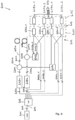
- the embodiment illustrated in Fig. 1 similarly as the embodiments illustrated in Figs. 2 to 4 , comprises exactly one optical fibre 109a.
- the light combining system 110 is configured to receive the first polarisation component 111a_1 of the respective backscatter light 111a and to receive the first reference radiation 106_1 and to provide a first light combining system radiation output 116a_1 based on the inputs 111a_1, 106_1.
- the combining system 110 is configured to receive the second polarisation component 111a_2 of the respective backscatter 111a and to receive the second reference radiation 106_2 and to provide a second light combining system radiation output 116a_2 based on the inputs 111a_2, 106_2.
- the detection system 114 is configured to detect the first light combining system radiation output 116a_1 and the second light combining system radiation output 116a_2 separately.
- the detection system 114 comprises the first detection component 117_1 and a second detection component 117_2 which each comprises one or more light sensitive elements.
- the embodiment 100 of Fig. 1 further comprises at least one modulator 118 which is configured to receive one of the at least one injection radiation 105 and provide fibre input radiation 119.
- the modulator 118 is configured to modulate the injection radiation with respect to at least one optical characteristics, as has been explained above.
- the respective fibre input radiation portion 120a (injected into the fibre 109a) is thereby derived from the fibre input radiation 119.
- the respective fibre input radiation portions 120a substantially correspond to or are equal to the fibre input radiation 119, while in embodiments of multiple optical sensing fibres, the fibre input radiation 119 may be divided into plural equal power (or different power) in fibre input radiation portions.
- the light combining system radiation outputs 116a_1, 116a_2 may comprise each one or more components, for example which are shifted in phase which are then detected separately by the detection components 117_1, 117_2.
- the system 100 further comprises in particular for every one of the one or more optical fibres 109, a fibre associated circulator 121a which is arranged in an injection radiation path between the modulator 118 and the respective fibre 109a and/or which is arranged in a detection radiation path between the polarisation splitting device 115a (or the combining system 110) and the respective fibre 109a.
- the circulator 121a allows direction specific optical communication between different input/output ports. For example, the circulator 121a allows to pass the fibre input radiation 119 (as the respective fibre input radiation portion 120a), to the respective fibre 109a and/or to pass the respective backscatter light 111a returned from the respective fibre 109a to the respective polarisation splitting device 115a or to the light combining system 110.
- the light combining system 110 comprises in the embodiment illustrated in Fig. 1 for every one of the one or more optical fibres and for each polarisation component of the backscatter light or for the backscatter light, a respective light combining device 122a (in particular 122a_1, 122a_2).
- the light combining device 122a_1 is configured to receive the first polarisation component 111a_1 of the backscatter light 111a and the first reference radiation portion 106_1 and is configured to combine the input radiations and output the first light combining system radiation output 116a_1.
- the light combining device 122a_2 performs a similar function based on the second polarisation component 111a_2 and the second reference radiation portion 106_2 to provide the second combining system radiation output 116a_2.
- only one light combining device may be provided for each of the optical fibres 109 which is then configured to combine the respective backscatter light with a reference radiation portion.
- the embodiment 100 illustrated in Fig. 1 further comprises a processor or in general processing system 123 which receives from the detection system 114 signals indicating the intensities of the detected light combining system radiation outputs 113 and is configured to determine strain and/or temperature and/or acoustic disturbance of the one or more optical fibres (see the description of the processor above).
- a processor or in general processing system 123 which receives from the detection system 114 signals indicating the intensities of the detected light combining system radiation outputs 113 and is configured to determine strain and/or temperature and/or acoustic disturbance of the one or more optical fibres (see the description of the processor above).
- the respective light combining devices 322a_1, 322a_2 are configured or comprise each a 2x2 (e.g. fused) fibre coupler having two inputs and two outputs each.
- the first/second polarisation component 311a_1, 311a_2 are respectively combined with the first/second reference radiation portion 306_1, 306_2 and the combined outputs 316a_1 and 316a_2 each comprise two components, in particular components which are shifted in phase which are supplied to the detection components 317_1, 317_2.
- the detection components 317_1, 317_2 detect the two components of each of the outputs 316a_1, 316a_2 separately.
- the detection components 317_1, 317_2 could especially be balanced photodiodes which may rely on the two phase-shifted outputs of the 2x2 couplers.
- the system 500 illustrated in Fig. 5 enables or provides polarisation-diverse coherent detection for two optical fibres 509a, 509b.
- the system 500 comprises downstream the primary radiation splitter 503 - which is configured as a 1x3 (e.g. fused) fibre coupler or splitter - two 1x2 (e.g.
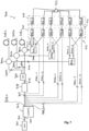
- the distributed sensing system 700 illustrated in a schematic manner in Fig. 7 provides polarisation-diverse coherent detection for N optical sensing fibres, in the present case the three fibres 709a, 709b, 709c.
- the primary radiation splitter 703 has one input port and 2xN+1 output ports. Thereby, for every of the N fibres, two reference radiation portions are provided which are combined in the combining system 710 with respective two different polarisation components of the respective backscatter light. Additionally, the primary radiation splitter 703 provides the one injection radiation 705 which is supplied to a modulator 718 which outputs fibre input radiation 719.
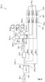
- the respective reference radiation portions 806a, 806b, 806c are combined in the combining system 810 with the respective backscatter light 811a, 811b, 811c and the respective combined outputs are supplied to the detection system 814 which separately detects the combined outputs from the different fibres.
- Embodiments of the present invention support COTDR (coherent optical time-domain reflectometry) or BOTDR (Brillouin OTDR). Other embodiments may support DAS (distributed acoustic sensing) or DTS (distributed temperature sensing) or DSS (distributed strain sensing) for one or multiple optical fibres. Embodiments of the present invention may support detection, in particular coherent detection, of two or more differently polarized signals from each backscatter light.
- the processor may be configured to receive digital signals or to perform a conversion of analogue signals to digital signals.
Landscapes
- Physics & Mathematics (AREA)
- General Physics & Mathematics (AREA)
- Optical Transform (AREA)
Priority Applications (2)
| Application Number | Priority Date | Filing Date | Title |
|---|---|---|---|
| EP23218873.0A EP4575415A1 (de) | 2023-12-20 | 2023-12-20 | Verteiltes erfassungssystem mit kohärenter detektion |
| US18/988,297 US20250207955A1 (en) | 2023-12-20 | 2024-12-19 | Distributed sensing system providing coherent detection |
Applications Claiming Priority (1)
| Application Number | Priority Date | Filing Date | Title |
|---|---|---|---|
| EP23218873.0A EP4575415A1 (de) | 2023-12-20 | 2023-12-20 | Verteiltes erfassungssystem mit kohärenter detektion |
Publications (1)
| Publication Number | Publication Date |
|---|---|
| EP4575415A1 true EP4575415A1 (de) | 2025-06-25 |
Family
ID=89224807
Family Applications (1)
| Application Number | Title | Priority Date | Filing Date |
|---|---|---|---|
| EP23218873.0A Pending EP4575415A1 (de) | 2023-12-20 | 2023-12-20 | Verteiltes erfassungssystem mit kohärenter detektion |
Country Status (2)
| Country | Link |
|---|---|
| US (1) | US20250207955A1 (de) |
| EP (1) | EP4575415A1 (de) |
Families Citing this family (1)
| Publication number | Priority date | Publication date | Assignee | Title |
|---|---|---|---|---|
| US12436043B2 (en) * | 2022-09-29 | 2025-10-07 | The Government Of The United States Of America, As Represented By The Secretary Of The Navy | Methods providing distributed temperature and strain measurements and related sensors |
Citations (6)
| Publication number | Priority date | Publication date | Assignee | Title |
|---|---|---|---|---|
| US20050134861A1 (en) * | 2003-12-23 | 2005-06-23 | Kringlebotn Jon T. | Wavelength reference system for optical measurements |
| US20180073959A1 (en) * | 2016-09-09 | 2018-03-15 | Viavi Solutions Inc. | Temperature or strain distribution sensor |
| EP2816323B1 (de) | 2013-06-18 | 2019-10-16 | Siemens Aktiengesellschaft | Verfahren und Vorrichtung zur Messung der akustischen Umgebung einer Glasfaser |
| EP3680638A1 (de) * | 2019-01-11 | 2020-07-15 | AiQ Dienstleistungen UG (haftungsbeschränkt) | Verteilte akustische erfassung und sensorintegritätsüberwachung |
| US20200370949A1 (en) * | 2019-05-22 | 2020-11-26 | Nec Laboratories America, Inc | Performance of rayleigh-based phase-otdr with correlation-based diversity combining and bias removal |
| US11469816B2 (en) | 2018-10-03 | 2022-10-11 | Luna Innovations Germany Gmbh | Distributed sensing apparatus |
-
2023
- 2023-12-20 EP EP23218873.0A patent/EP4575415A1/de active Pending
-
2024
- 2024-12-19 US US18/988,297 patent/US20250207955A1/en active Pending
Patent Citations (6)
| Publication number | Priority date | Publication date | Assignee | Title |
|---|---|---|---|---|
| US20050134861A1 (en) * | 2003-12-23 | 2005-06-23 | Kringlebotn Jon T. | Wavelength reference system for optical measurements |
| EP2816323B1 (de) | 2013-06-18 | 2019-10-16 | Siemens Aktiengesellschaft | Verfahren und Vorrichtung zur Messung der akustischen Umgebung einer Glasfaser |
| US20180073959A1 (en) * | 2016-09-09 | 2018-03-15 | Viavi Solutions Inc. | Temperature or strain distribution sensor |
| US11469816B2 (en) | 2018-10-03 | 2022-10-11 | Luna Innovations Germany Gmbh | Distributed sensing apparatus |
| EP3680638A1 (de) * | 2019-01-11 | 2020-07-15 | AiQ Dienstleistungen UG (haftungsbeschränkt) | Verteilte akustische erfassung und sensorintegritätsüberwachung |
| US20200370949A1 (en) * | 2019-05-22 | 2020-11-26 | Nec Laboratories America, Inc | Performance of rayleigh-based phase-otdr with correlation-based diversity combining and bias removal |
Also Published As
| Publication number | Publication date |
|---|---|
| US20250207955A1 (en) | 2025-06-26 |
Similar Documents
| Publication | Publication Date | Title |
|---|---|---|
| CN102519501B (zh) | 一种采用波分复用器的光纤多通道周界传感系统 | |
| US10113935B2 (en) | Distributed multi-channel coherent optical fiber sensing system | |
| Berkoff et al. | Fiber Bragg grating array sensor system using a bandpass wavelength division multiplexer and interferometric detection | |
| CN105136177B (zh) | 一种亚毫米空间分辨率的分布式光纤传感装置及方法 | |
| US4334781A (en) | Optical sensing system | |
| US9939294B2 (en) | Demodulation system for 3D-matrix multi-channel fiber optic sensing | |
| Gubaidullin et al. | Application of Gaussian function for modeling two-frequency radiation from addressed FBG | |
| KR20230124055A (ko) | 헤테로다인 광학 검출을 사용하여 복굴절 섬유 브래그격자 센서를 인터로게이팅하는 방법 및 시스템 | |
| EP4575415A1 (de) | Verteiltes erfassungssystem mit kohärenter detektion | |
| CN207036297U (zh) | 一种光纤光栅测温系统 | |
| JP4797102B2 (ja) | 光ネットワーク監視システム及びその方法 | |
| CN105806379B (zh) | 弱反射光纤布拉格光栅-珐泊腔传感器的解调系统 | |
| IL146075A (en) | Intrinsic security of fiber optic communication links | |
| Naim et al. | Real-time monitoring in passive optical networks using a superluminescent LED with uniform and phase-shifted fiber Bragg gratings | |
| KR100483147B1 (ko) | 광섬유 길이 측정시스템 및 측정방법 | |
| MY201092A (en) | System for distributed monitoring of perturbation in gigabit passive optical network (gpon) architecture and method thereof | |
| RU2624837C1 (ru) | Волоконно-оптическое интерферометрическое устройство для регистрации фазовых сигналов | |
| Sikdar et al. | Polarization multiplexed interrogation technique for FBG sensor array | |
| RU2437063C1 (ru) | Волоконно-оптическая сенсорная система | |
| KR20240017284A (ko) | 광섬유 간섭계 기반의 균형 광 검출기 및 이를 사용한 분포형 음향 측정 센서 시스템 | |
| Wu et al. | Fiber Bragg grating sensors interrogation system using arrayed waveguide gratings demultiplexer | |
| JP5118772B2 (ja) | 光インターコネクト | |
| CN113252088A (zh) | 一种多波长的分布式光纤传感系统及方法 | |
| Mansurov et al. | Universal Fiber Optic Coupler/Sensor | |
| JP3282644B2 (ja) | 光部品検査装置 |
Legal Events
| Date | Code | Title | Description |
|---|---|---|---|
| PUAI | Public reference made under article 153(3) epc to a published international application that has entered the european phase |
Free format text: ORIGINAL CODE: 0009012 |
|
| STAA | Information on the status of an ep patent application or granted ep patent |
Free format text: STATUS: THE APPLICATION HAS BEEN PUBLISHED |
|
| AK | Designated contracting states |
Kind code of ref document: A1 Designated state(s): AL AT BE BG CH CY CZ DE DK EE ES FI FR GB GR HR HU IE IS IT LI LT LU LV MC ME MK MT NL NO PL PT RO RS SE SI SK SM TR |
|
| STAA | Information on the status of an ep patent application or granted ep patent |
Free format text: STATUS: REQUEST FOR EXAMINATION WAS MADE |
|
| 17P | Request for examination filed |
Effective date: 20250813 |
|
| STAA | Information on the status of an ep patent application or granted ep patent |
Free format text: STATUS: EXAMINATION IS IN PROGRESS |
|
| 17Q | First examination report despatched |
Effective date: 20251210 |