EP4575333A2 - Air conditioner - Google Patents
Air conditioner Download PDFInfo
- Publication number
- EP4575333A2 EP4575333A2 EP25175656.5A EP25175656A EP4575333A2 EP 4575333 A2 EP4575333 A2 EP 4575333A2 EP 25175656 A EP25175656 A EP 25175656A EP 4575333 A2 EP4575333 A2 EP 4575333A2
- Authority
- EP
- European Patent Office
- Prior art keywords
- water
- air
- tank
- channel
- sensible heat
- Prior art date
- Legal status (The legal status is an assumption and is not a legal conclusion. Google has not performed a legal analysis and makes no representation as to the accuracy of the status listed.)
- Pending
Links
Images



Classifications
-
- F—MECHANICAL ENGINEERING; LIGHTING; HEATING; WEAPONS; BLASTING
- F24—HEATING; RANGES; VENTILATING
- F24F—AIR-CONDITIONING; AIR-HUMIDIFICATION; VENTILATION; USE OF AIR CURRENTS FOR SCREENING
- F24F1/00—Room units for air-conditioning, e.g. separate or self-contained units or units receiving primary air from a central station
- F24F1/0007—Indoor units, e.g. fan coil units
-
- F—MECHANICAL ENGINEERING; LIGHTING; HEATING; WEAPONS; BLASTING
- F24—HEATING; RANGES; VENTILATING
- F24F—AIR-CONDITIONING; AIR-HUMIDIFICATION; VENTILATION; USE OF AIR CURRENTS FOR SCREENING
- F24F1/00—Room units for air-conditioning, e.g. separate or self-contained units or units receiving primary air from a central station
- F24F1/0007—Indoor units, e.g. fan coil units
- F24F1/0087—Indoor units, e.g. fan coil units with humidification means
-
- F—MECHANICAL ENGINEERING; LIGHTING; HEATING; WEAPONS; BLASTING
- F24—HEATING; RANGES; VENTILATING
- F24F—AIR-CONDITIONING; AIR-HUMIDIFICATION; VENTILATION; USE OF AIR CURRENTS FOR SCREENING
- F24F1/00—Room units for air-conditioning, e.g. separate or self-contained units or units receiving primary air from a central station
- F24F1/02—Self-contained room units for air-conditioning, i.e. with all apparatus for treatment installed in a common casing
- F24F1/032—Self-contained room units for air-conditioning, i.e. with all apparatus for treatment installed in a common casing characterised by heat exchangers
- F24F1/0323—Self-contained room units for air-conditioning, i.e. with all apparatus for treatment installed in a common casing characterised by heat exchangers by the mounting or arrangement of the heat exchangers
-
- F—MECHANICAL ENGINEERING; LIGHTING; HEATING; WEAPONS; BLASTING
- F24—HEATING; RANGES; VENTILATING
- F24F—AIR-CONDITIONING; AIR-HUMIDIFICATION; VENTILATION; USE OF AIR CURRENTS FOR SCREENING
- F24F13/00—Details common to, or for air-conditioning, air-humidification, ventilation or use of air currents for screening
-
- F—MECHANICAL ENGINEERING; LIGHTING; HEATING; WEAPONS; BLASTING
- F24—HEATING; RANGES; VENTILATING
- F24F—AIR-CONDITIONING; AIR-HUMIDIFICATION; VENTILATION; USE OF AIR CURRENTS FOR SCREENING
- F24F13/00—Details common to, or for air-conditioning, air-humidification, ventilation or use of air currents for screening
- F24F13/02—Ducting arrangements
- F24F13/06—Outlets for directing or distributing air into rooms or spaces, e.g. ceiling air diffuser
-
- F—MECHANICAL ENGINEERING; LIGHTING; HEATING; WEAPONS; BLASTING
- F24—HEATING; RANGES; VENTILATING
- F24F—AIR-CONDITIONING; AIR-HUMIDIFICATION; VENTILATION; USE OF AIR CURRENTS FOR SCREENING
- F24F13/00—Details common to, or for air-conditioning, air-humidification, ventilation or use of air currents for screening
- F24F13/22—Means for preventing condensation or evacuating condensate
-
- F—MECHANICAL ENGINEERING; LIGHTING; HEATING; WEAPONS; BLASTING
- F24—HEATING; RANGES; VENTILATING
- F24F—AIR-CONDITIONING; AIR-HUMIDIFICATION; VENTILATION; USE OF AIR CURRENTS FOR SCREENING
- F24F5/00—Air-conditioning systems or apparatus not covered by F24F1/00 or F24F3/00, e.g. using solar heat or combined with household units such as an oven or water heater
- F24F5/0007—Air-conditioning systems or apparatus not covered by F24F1/00 or F24F3/00, e.g. using solar heat or combined with household units such as an oven or water heater cooling apparatus specially adapted for use in air-conditioning
- F24F5/0035—Air-conditioning systems or apparatus not covered by F24F1/00 or F24F3/00, e.g. using solar heat or combined with household units such as an oven or water heater cooling apparatus specially adapted for use in air-conditioning using evaporation
-
- F—MECHANICAL ENGINEERING; LIGHTING; HEATING; WEAPONS; BLASTING
- F24—HEATING; RANGES; VENTILATING
- F24F—AIR-CONDITIONING; AIR-HUMIDIFICATION; VENTILATION; USE OF AIR CURRENTS FOR SCREENING
- F24F1/00—Room units for air-conditioning, e.g. separate or self-contained units or units receiving primary air from a central station
- F24F1/02—Self-contained room units for air-conditioning, i.e. with all apparatus for treatment installed in a common casing
- F24F1/039—Self-contained room units for air-conditioning, i.e. with all apparatus for treatment installed in a common casing using water to enhance cooling, e.g. spraying onto condensers
-
- F—MECHANICAL ENGINEERING; LIGHTING; HEATING; WEAPONS; BLASTING
- F24—HEATING; RANGES; VENTILATING
- F24F—AIR-CONDITIONING; AIR-HUMIDIFICATION; VENTILATION; USE OF AIR CURRENTS FOR SCREENING
- F24F12/00—Use of energy recovery systems in air conditioning, ventilation or screening
-
- F—MECHANICAL ENGINEERING; LIGHTING; HEATING; WEAPONS; BLASTING
- F24—HEATING; RANGES; VENTILATING
- F24F—AIR-CONDITIONING; AIR-HUMIDIFICATION; VENTILATION; USE OF AIR CURRENTS FOR SCREENING
- F24F12/00—Use of energy recovery systems in air conditioning, ventilation or screening
- F24F12/001—Use of energy recovery systems in air conditioning, ventilation or screening with heat-exchange between supplied and exhausted air
-
- F—MECHANICAL ENGINEERING; LIGHTING; HEATING; WEAPONS; BLASTING
- F24—HEATING; RANGES; VENTILATING
- F24F—AIR-CONDITIONING; AIR-HUMIDIFICATION; VENTILATION; USE OF AIR CURRENTS FOR SCREENING
- F24F6/00—Air-humidification, e.g. cooling by humidification
- F24F2006/008—Air-humidifier with water reservoir
-
- Y—GENERAL TAGGING OF NEW TECHNOLOGICAL DEVELOPMENTS; GENERAL TAGGING OF CROSS-SECTIONAL TECHNOLOGIES SPANNING OVER SEVERAL SECTIONS OF THE IPC; TECHNICAL SUBJECTS COVERED BY FORMER USPC CROSS-REFERENCE ART COLLECTIONS [XRACs] AND DIGESTS
- Y02—TECHNOLOGIES OR APPLICATIONS FOR MITIGATION OR ADAPTATION AGAINST CLIMATE CHANGE
- Y02B—CLIMATE CHANGE MITIGATION TECHNOLOGIES RELATED TO BUILDINGS, e.g. HOUSING, HOUSE APPLIANCES OR RELATED END-USER APPLICATIONS
- Y02B30/00—Energy efficient heating, ventilation or air conditioning [HVAC]
- Y02B30/54—Free-cooling systems
Definitions
- the present invention relates to an air conditioner.
- Patent Literature 1 An air conditioner of an evaporative cooling type is known which takes in air in a room and blows air, which is cooled by lowering the ambient temperature using the heat of vaporization of water, into the room (e.g., Patent Literature 1).
- the air conditioner (evaporative cooler) of Patent Literature 1 includes an air blowing means disposed in a casing, a first channel, and a second channel.
- the first channel communicates with an inlet and a first outlet of the casing, and guides an air flow generated by the air blowing means to the first outlet.
- the second channel communicates with the inlet and a second outlet, and guides the air flow generated by the air blowing means to the second outlet.
- a vaporizing means is disposed in the second channel to cool air flowing through the second channel by the heat of vaporization of water.
- a heat exchanger is provided for exchanging heat between the air flow cooled by the vaporizing means in the second channel and the air flow flowing through the first channel.
- the vaporizing means sprays atomized water (unevaporated sprayed water), and air having its absolute humidity increased due to evaporation of the atomized water (evaporated sprayed water) flows in an area downstream of the vaporizing means.
- the air with increased humidity is blown out as exhaust air from the second outlet which is an exit of the second channel.
- the air flow flowing through the first channel cooled via the heat exchanger is blown out from the first outlet to a space to be air-conditioned as supply air.
- Patent Literature 1 the air flowing through the second channel by the air blowing means passes through a plurality of tubes of a sensible heat exchanger, and the air flowing through the first channel by the air blowing means passes around the plurality of tubes, so that heat is exchanged between the air flowing through the second channel and the air flowing through the first channel.
- the present invention has been made in view of such circumstances, and an object thereof is to provide an air conditioner capable of improving cooling capacity.
- An air conditioner includes a housing having a first outlet and a second outlet, a first channel communicating with the first outlet, a second channel communicating with the second outlet, a tank unit to hold water for cooling first air flowing in the first channel and second air flowing in the second channel, a cooling unit to cool the first air by heat of vaporization of the water held in the tank unit, a water supply channel for supplying the water held in the tank unit to the cooling unit, and a water recovery channel for collecting water remaining in the cooling unit to the tank unit.
- the cooling unit and the tank unit are connected by the water recovery channel to collect water remaining in the cooling unit to the tank unit.
- the cooling unit vaporizes water held in the tank unit, and cools the first air by the heat of vaporization of water, that is, latent heat.
- some water supplied from the tank unit to the cooling unit remains in a liquid state in the cooling unit without being vaporized, and the remaining liquid water is collected to the tank unit by the water recovery channel.
- the water remaining in the cooling unit which is also cooled by the heat of vaporization of the vaporized water as with the first air, is collected to the tank unit, whereby the temperature of the water held in the tank unit can be lowered.
- the cooling efficiency in the cooling unit can be improved. That is, the heat of vaporization generated in the cooling unit is reused by collecting the water remaining in the cooling unit as a cold energy medium, whereby the cooling capacity of the air conditioner can be improved.
- the tank unit of the air conditioner includes a first tank communicating with the water supply channel and the water recovery channel, and a second tank to hold water to be supplied from outside the housing and to be supplied to the first tank.
- the tank unit includes a first tank communicating with the water supply channel and the water recovery channel, and a second tank to hold water to be supplied from outside the housing and to be supplied to the first tank. Therefore, in collecting the water remaining in the cooling unit, a circulation path through which the water circulates is formed in the order of the first tank as a starting point, the water supply channel, the cooling unit, the water recovery channel, and the first tank as an endpoint.
- a path configuration is employed in which the second tank is not directly included in the circulation path in this way, which can reduce the influence of the temperature rise due to the temperature of water to be held in the second tank, that is, water to be supplied from the outside, and further improve the cooling efficiency in the cooling unit.
- the first tank of the air conditioner according to an aspect of the present disclosure has a smaller volume than the second tank.
- the volume of the first tank is smaller than the volume of the second tank, which can reduce the influence of the temperature of the water to be held in the second tank, and further improve the cooling efficiency in the cooling unit.
- the second water supply parts 223 are located downstream of the first paths 221 above the entrances of the second paths 222 of the sensible heat exchanger 22. That is, the second water supply parts 223 are provided closer to the exits of the first paths 221 than to the entrances thereof and above the entrances of the second paths 222. In the first paths 221 of the sensible heat exchanger 22, the closer to the second water supply parts 223, the lower the temperature due to the water supplied from the first tank 71.
- the temperature of the first air at the entrance of the first path 221 corresponds to the room temperature of the space to be air-conditioned, and is the highest temperature in the temperature distribution of the first air in the first path 221.
- Portions of the second paths 222 extending from an upper side of the sensible heat exchanger 22 to its lower side, the drain pan 13 provided below the exits of the second paths 222, and the second channel 51 extending upward from the drain pan 13 constitute a gas-liquid separator for separating water from a mixture of the second air and water supplied from the second water supply parts 223.
- the gas-liquid separator separates water from the second air, thus preventing an increase in the absolute humidity of the second air.
- Pairs of parallel ribs 225 provided on side surfaces on the long sides and inner wall surfaces by which the V-shaped notch is defined are defined as vertical ribs.
- the vertical ribs are arranged side by side at equal intervals on the side surfaces and the inner wall surfaces.
- the vertical ribs on one side surface corresponding to the long side and the vertical ribs on the other side surface are staggered so as not to overlap with each other in a side view. That is, the vertical ribs on each side surface are provided such that, in a side view, a vertical rib on one side surface is located between adjacent vertical ribs on the other side surface.
- the vertical ribs on the respective inner wall surfaces facing each other are staggered.
- the vertical ribs constituted by the pairs of parallel ribs 225 are provided in association with the second paths 222 of the sensible heat exchanger 22.
- the second water supply part 223 is located above the sensible heat exchanger 22 so that, as shown in FIG. 5 , a direction where each vertical rib extends agrees with the vertical direction of each of the metal plates constituting the first paths 221 and the second paths 222.
- the second water supply part 223 is provided so that a rib of a pair of ribs 225 constituting a vertical rib is aligned with a second path of adjacent two second paths 222.
- the second water supply part 223 is provided so that a first path 221 is positioned between a pair of ribs 225 constituting a vertical rib.
- the cooling unit 2 employs a configuration in which the remaining water is collected at the first tank 71 by the first water recovery channel 91 and the second water recovery channel 92.
- the cooling unit 2 may employ a configuration in which the first water recovery channel 91 is connected to the second water supply parts 223 and a pump is provided in the first water recovery channel 91 so that only the second water recovery channel 92 is connected to the first tank 71. This allows for cooling the circulating water more efficiently.
- various configurations can be employed for the cooling unit 2 and the shape of channels of water in the cooling unit 2.
- various types of heat exchangers can be applied to the cooling unit 2. As an example, not only heat is exchanged between at least one of the first air and the second air and water, but also a configuration for simply cooling water may be used as a substitute for the vaporization filter 21 or the sensible heat exchanger 22, or be included additionally.
- the vaporization filter is provided downstream of the sensible heat exchanger in a flow direction of the first air and cools the first air by latent heat of water supplied from the tank unit.
- the air conditioner includes a supply channel for supplying water held in the tank unit to the sensible heat exchanger and the vaporization filter of the cooling unit, and a water recovery channel for collecting water remaining in the sensible heat exchanger and the vaporization filter to the tank unit.
- the housing has an outlet for sucking the first air.
- the outlet, the sensible heat exchanger, and the vaporization filter are disposed linearly side by side, the sensible heat exchanger faces the outlet, and the vaporization filter faces the sensible heat exchanger.
- the first outlet and the second outlet are located above the sensible heat exchanger and the vaporization filter, and a first fan for blowing out the first air having passed through the vaporization filter from the first outlet, a second fan for blowing out the second air having passed through the sensible heat exchanger from the second outlet, and a motor for driving both fans are provided below the first outlet and the outlet in the housing and above the sensible heat exchanger and the vaporization filter.
- the outlet, the sensible heat exchanger, and the vaporization filter, which are disposed in the housing, are horizontally linearly aligned.
- the air conditioner according to any one of Appendices A1 to A3 includes a second water supply part that is disposed in a supply channel between the tank unit and the sensible heat exchanger, and disposed at the upper part of the sensible heat exchanger to receive and supply water supplied from the water supply channel to the second channel.
- the second water supply part is provided above the sensible heat exchanger and at a position proximate to an exit of the first air in the first path.
- the air conditioner includes a housing having a first outlet and a second outlet, a first channel communicating with the first outlet, a second channel communicating with the second outlet, a tank unit to hold water for cooling first air flowing in the first channel and second air flowing in the second channel, and a cooling unit that cools the first air by heat of vaporization of water held in the tank unit.
- the cooling unit includes a sensible heat exchanger and a vaporization filter.
- the sensible heat exchanger includes a first channel through which the first air flows and a second channel through which the second air flows, cools the second air by heat exchange with water supplied from the tank unit, and cools the first air by sensible heat exchange between the cooled second air and the first air.
- the vaporization filter is provided downstream of the sensible heat exchanger in a flow direction of the first air and cools the first air by latent heat of water supplied from the tank unit.
- a supply channel for supplying water held in the tank unit to the sensible heat exchanger and the vaporization filter of the cooling unit is provided.
- the air conditioner further includes a second water supply part disposed in the water supply channel between the tank unit and the sensible heat exchanger and provided above the sensible heat exchanger to receive water supplied from the water supply channel and supply the water to the second channel of the heat exchanger.
- the air conditioner according to Appendix B1 further includes a water recovery channel for collecting water remaining in the sensible heat exchanger and the vaporization filter to the tank unit, the tank unit being provided below the sensible heat exchanger.
- the housing has an inlet for sucking the first air
- the housing inlet, the sensible heat exchanger, and the vaporization filter are disposed side by side, and the first outlet and the second outlet are provided at positions above the sensible heat exchanger and the vaporization filter, and in the same order along the same direction as the direction from the sensible heat exchanger toward the vaporization filter.
- the first outlet and the second outlet are located above the sensible heat exchanger and the vaporization filter, and a first fan for blowing out the first air having passed through the vaporization filter from the first outlet, a second fan for blowing out the second air having passed through the sensible heat exchanger from the second outlet, and a motor for driving both fans are provided below the first outlet and the second outlet in the housing and above the sensible heat exchanger and the vaporization filter.
- the first fan, the second fan, and the motor are provided above the second water supply part.
Landscapes
- Engineering & Computer Science (AREA)
- Chemical & Material Sciences (AREA)
- Combustion & Propulsion (AREA)
- Mechanical Engineering (AREA)
- General Engineering & Computer Science (AREA)
- Life Sciences & Earth Sciences (AREA)
- Sustainable Development (AREA)
- Physics & Mathematics (AREA)
- Thermal Sciences (AREA)
- Devices For Blowing Cold Air, Devices For Blowing Warm Air, And Means For Preventing Water Condensation In Air Conditioning Units (AREA)
- Heat-Exchange Devices With Radiators And Conduit Assemblies (AREA)
- Other Air-Conditioning Systems (AREA)
Abstract
Description
- The present invention relates to an air conditioner.
- An air conditioner of an evaporative cooling type is known which takes in air in a room and blows air, which is cooled by lowering the ambient temperature using the heat of vaporization of water, into the room (e.g., Patent Literature 1). The air conditioner (evaporative cooler) of
Patent Literature 1 includes an air blowing means disposed in a casing, a first channel, and a second channel. The first channel communicates with an inlet and a first outlet of the casing, and guides an air flow generated by the air blowing means to the first outlet. The second channel communicates with the inlet and a second outlet, and guides the air flow generated by the air blowing means to the second outlet. A vaporizing means is disposed in the second channel to cool air flowing through the second channel by the heat of vaporization of water. A heat exchanger is provided for exchanging heat between the air flow cooled by the vaporizing means in the second channel and the air flow flowing through the first channel. In the second channel where the vaporizing means is disposed, the vaporizing means sprays atomized water (unevaporated sprayed water), and air having its absolute humidity increased due to evaporation of the atomized water (evaporated sprayed water) flows in an area downstream of the vaporizing means. The air with increased humidity is blown out as exhaust air from the second outlet which is an exit of the second channel. The air flow flowing through the first channel cooled via the heat exchanger is blown out from the first outlet to a space to be air-conditioned as supply air. - In
Patent Literature 1, the air flowing through the second channel by the air blowing means passes through a plurality of tubes of a sensible heat exchanger, and the air flowing through the first channel by the air blowing means passes around the plurality of tubes, so that heat is exchanged between the air flowing through the second channel and the air flowing through the first channel. - [PTL 1]
JP2014-092338A - However, in the air conditioner of
Patent Literature 1, the air that has passed through a vaporization filter included in the vaporization means is discharged from the second outlet after heat exchange with the air that is supplied to the room by the sensible heat exchanger, and thus cannot be efficiently cooled. - The present invention has been made in view of such circumstances, and an object thereof is to provide an air conditioner capable of improving cooling capacity.
- An air conditioner according to an aspect of the present disclosure includes a housing having a first outlet and a second outlet, a first channel communicating with the first outlet, a second channel communicating with the second outlet, a tank unit to hold water for cooling first air flowing in the first channel and second air flowing in the second channel, a cooling unit to cool the first air by heat of vaporization of the water held in the tank unit, a water supply channel for supplying the water held in the tank unit to the cooling unit, and a water recovery channel for collecting water remaining in the cooling unit to the tank unit.
- In this aspect, the cooling unit and the tank unit are connected by the water recovery channel to collect water remaining in the cooling unit to the tank unit. The cooling unit vaporizes water held in the tank unit, and cools the first air by the heat of vaporization of water, that is, latent heat. In this case, some water supplied from the tank unit to the cooling unit remains in a liquid state in the cooling unit without being vaporized, and the remaining liquid water is collected to the tank unit by the water recovery channel. The water remaining in the cooling unit, which is also cooled by the heat of vaporization of the vaporized water as with the first air, is collected to the tank unit, whereby the temperature of the water held in the tank unit can be lowered. By using the water in the tank unit whose temperature has been lowered in this way, the cooling efficiency in the cooling unit can be improved. That is, the heat of vaporization generated in the cooling unit is reused by collecting the water remaining in the cooling unit as a cold energy medium, whereby the cooling capacity of the air conditioner can be improved.
- The tank unit of the air conditioner according to an aspect of the present disclosure includes a first tank communicating with the water supply channel and the water recovery channel, and a second tank to hold water to be supplied from outside the housing and to be supplied to the first tank.
- In this aspect, the tank unit includes a first tank communicating with the water supply channel and the water recovery channel, and a second tank to hold water to be supplied from outside the housing and to be supplied to the first tank. Therefore, in collecting the water remaining in the cooling unit, a circulation path through which the water circulates is formed in the order of the first tank as a starting point, the water supply channel, the cooling unit, the water recovery channel, and the first tank as an endpoint. A path configuration is employed in which the second tank is not directly included in the circulation path in this way, which can reduce the influence of the temperature rise due to the temperature of water to be held in the second tank, that is, water to be supplied from the outside, and further improve the cooling efficiency in the cooling unit.
- The first tank of the air conditioner according to an aspect of the present disclosure has a smaller volume than the second tank.
- In this aspect, the volume of the first tank is smaller than the volume of the second tank, which can reduce the influence of the temperature of the water to be held in the second tank, and further improve the cooling efficiency in the cooling unit.
- In the air conditioner according to an aspect of the present disclosure, water in the second tank is supplied to the first tank when an amount of water in the first tank is smaller than or equal to a predetermined value.
- In this aspect, the second tank has a water supply port at a location, for example, corresponding to a predetermined water level in the first tank, thereby when a level of water in the first tank is lower than or equal to a predetermined level, that is, when the amount of water in the first tank is lower than or equal to a predetermined amount, water in the second tank is supplied to the first tank. The water in the first tank is reduced while being vaporized by the cooling unit and then blown out to the space to be air-conditioned together with the first air, and when the amount of water in the first tank is smaller than or equal to a predetermined value, the water in the second tank is supplied to the first tank. This can prevent a decrease in cooling efficiency due to shortage of water in the first tank.
- In the air conditioner according to an aspect of the present disclosure, an amount of water to be supplied from the second tank to the first tank at a time is smaller than or equal to half a total value of a volume of the first tank and a volume of the water supply channel, and a volume of the water recovery channel.
- In this aspect, when the amount of water in the first tank is smaller than or equal to the predetermined value, the predetermined amount of water in the second tank is supplied to the first tank each time. The predetermined amount, that is, the amount of water to be supplied from the second tank to the first tank at a time is set to be smaller than or equal to half the total value of the volume of the first tank, the volume of the water supply channel, and the volume of the water recovery channel. Therefore, the temperature of water circulating between the first tank and the cooling unit can be stabilized at a relatively low temperature, and the cooling efficiency in the cooling unit can be further improved.
- In the air conditioner according to an aspect of the present disclosure, the first tank is provided below the cooling unit, and a bottom surface of the first tank is provided below a bottom surface of the second tank.
- According to this aspect, the bottom surface of the first tank provided below the cooling unit is provided below the bottom surface of the second tank. Therefore, the first tank provided at the lowermost portion of a circulation path of water circulating between the first tank and the cooling unit can use gravity for collecting of water from the cooling unit and receiving of water from the second tank. This eliminates the need for a pump for collecting and supplying of water, and thus can reduce power consumption.
- The cooling unit of the air conditioner according to an aspect of the present disclosure may include: a sensible heat exchanger cooling first air by heat exchange with water supplied from the tank unit and cooling second air by sensible heat exchange between the cooled first air and the cooled second air; and an evaporation filter cooling the first air by latent heat of water supplied from the tank unit.
- In this aspect, the cooling unit includes: the sensible heat exchanger cooling first air by heat exchange with water supplied from the tank unit and cooling second air by sensible heat exchange between the cooled first air and the second air; and an evaporation filter cooling the first air by latent heat of water supplied from the tank unit. Therefore, the first air can be cooled by the sensible heat exchanger and the vaporization filter in two steps, and the temperature of the first air blown out from the first outlet can be lowered efficiently.
- The vaporization filter of the air conditioner according to an aspect of the present disclosure is provided downstream of the sensible heat exchanger in a flow direction of the first air.
- In this aspect, since the cooling capacity of the sensible heat exchanger with respect to the first air is lower than the cooling capacity of the vaporization filter, the first air can be efficiently cooled by providing the vaporization filter downstream of the sensible heat exchanger in the flow direction of the first air. That is, the sensible heat exchanger and the vaporization filter are provided in the first channel in the flow direction of the first air, so that the first air is cooled by the sensible heat exchanger, and then the vaporization filter having a total heat exchange capacity capable of exchanging not only sensible heat but also latent heat, and the first air can be thus efficiently cooled.
- The water supply channel of the air conditioner according to an aspect of the present disclosure includes a first water supply channel for supplying water to the vaporization filter and a second water supply channel for supplying water to the sensible heat exchanger, and a volumetric flow rate of water in the second supply channel is greater than a volumetric flow rate of water in the first water supply channel.
- In this aspect, the water supply channel includes the first water supply channel for supplying water to the vaporization filter and the second water supply channel for supplying water to the sensible heat exchanger, and the volumetric flow rate of water in the second supply channel is greater than the volumetric flow rate of water in the first water supply channel. That is, the amount of water to be supplied to the vaporization filter per unit time is smaller than the amount of water to be supplied to the sensible heat exchanger. This can increase the amount of water for cooling the second air by sensible heat in the sensible heat exchanger while reducing the amount of water vapor blown out to the space to be air-conditioned together with the first air. The cooling efficiency in the cooling unit can be further improved.
- In the air conditioner according to an aspect of the present disclosure, the second channel has a portion provided downstream of the sensible heat exchanger in a flow direction of the second air and including a gas-liquid separator to turn a direction of the second channel from a lower side to an upper side, and a fan motor to rotate a fan for conveying the first air and the second air is provided downstream of the gas-liquid separator.
- In this aspect, the portion of the second channel provided downstream of the sensible heat exchanger includes the gas-liquid separator to turn the flow direction of the second channel from the lower side to the upper side. Therefore, the water supplied from the tank unit and the second air can be separated by the gas-liquid separator, and the separated water can be efficiently collected to the tank unit via the water recovery channel. Since the fan motor to rotate the fan for conveying the first air and the second air is provided downstream of the gas-liquid separator, the fan motor can be cooled by the second air after being separated from the water supplied from the tank unit. Since the temperature of the second air is lower than that of the fan motor, the cooling capacity for the fan motor is excellent.
- The fan of the air conditioner according to an aspect of the present disclosure includes a first fan to convey first air and a second fan to convey second air, and a fan motor to rotate the first fan and the second fan is shared by the first fan and the second fan.
- In this aspect, the fan includes the first fan to convey the first air and the second fan to convey the second air, and the first fan and the second fan are rotated by the single fan motor. Therefore, it is not necessary to provide a fan motor for each of the first fan and the second fan, and it is possible to reduce the cost of parts, to reduce the size of the housing of the air conditioner, and to reduce the weight of the air conditioner.
- In the air conditioner according to an aspect of the present disclosure, a separation plate that separates the first channel from the second channel is provided between the first fan and the second fan.
- In this aspect, the separation plate that separates the first channel from the second channel is provided between the first fan and the fan motor, which can reliably prevent the first air and the second air from being mixed while cooling the fan motor with the second air. This configuration can prevent the temperature of the first air from rising due to the heat of the fan motor.
- A first water supply part to hold water supplied from the tank unit and to supply water to the vaporization filter is provided above the vaporization filter of the air conditioner according to an aspect of the present disclosure, the first water supply part is provided with a water supply hole communicating with the vaporization filter, and the fan is provided downstream of the vaporization filter in a flow direction of the first air.
- In this aspect, the first water supply part is provided above the vaporization filter, and is provided with the water supply hole communicating with the vaporization filter. Therefore, water supplied from the tank unit is temporarily held by the first water supply part. The held water is dripped from an upper portion of the vaporization filter through the water supply holes and supplied to the vaporization filter. Since the fan for conveying the first air is provided downstream of the vaporization filter in the flow direction of the first air, the inside of the vaporization filter becomes a negative pressure with respect to the atmospheric pressure. Therefore, by using the negative pressure, water held in the first water supply part is efficiently supplied to the vaporization filter through the water supply holes.
- The sensible heat exchanger of the air conditioner according to an aspect of the present disclosure communicates with a left-right direction and an up-down direction, one end of an opening in the left-right direction communicates with the first channel, a lower end in the up-down direction communicates with the second channel, a second water supply part to supply water to the sensible heat exchanger by diverting water supplied from the tank unit into a plurality of paths through which second air flows in the sensible heat exchanger is provided above the sensible heat exchanger, and the second water supply part is provided with a water receiver to receive water supplied from the tank unit, and a plurality of ribs radially provided from the water receiver toward the plurality of paths.
- In this aspect, the second water supply part provided above the sensible heat exchanger is provided with the water receiver to receive water supplied from the tank unit, and the plurality of ribs provided radially from the water receiver toward the plurality of paths. Therefore, water supplied from the tank unit can be diverted by each of the plurality of ribs provided radially, and the diverted water can be dripped into each of the plurality of paths through which the second air flows in the sensible heat exchanger. Accordingly, sensible heat exchange between the second air flowing through each of the plurality of paths of the sensible heat exchanger and water supplied from the tank unit can be efficiently performed, and cooling efficiency for the second air can be improved.
- The second water supply part of the air conditioner according to an aspect of the present disclosure is provided downstream of the plurality of paths in the sensible heat exchanger through which the first air flows in a flow direction of the first air.
- In this aspect, the second water supply part is provided downstream of each of the plurality of paths through which the first air flows in the sensible heat exchanger in the flow direction of the first air, that is, provided closer to an exit of each path through which the first air flows than to an entrance thereof in the sensible heat exchanger. The plurality of paths through which the first air flows in the sensible heat exchanger may have a lower temperature as the paths are located closer to the second water supply port due to the water supplied from the tank unit. By providing the second water supply unit downstream, that is, toward the outlet, a large temperature difference between the first air and the water can develop across the paths, and the cooling efficiency for the first air can be further improved.
- The cooling capacity of the air conditioner can be improved.
-
- [
FIG. 1] FIG. 1 is a schematic sectional view of an air conditioner according to a first embodiment, illustrating an example configuration. - [
FIG. 2] FIG. 2 is an external perspective view of the air conditioner. - [
FIG. 3] FIG. 3 is a schematic perspective view of a vaporization filter, illustrating an example configuration. - [
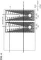
FIG. 4] FIG. 4 is a schematic plan view of second water supply parts of a sensible heat exchanger, illustrating an example configuration. - [
FIG. 5] FIG. 5 is an explanatory view for explaining a main part of a second water supply part. - Hereinafter, an embodiment will be described with reference to the drawings.
FIG. 1 is a schematic sectional view of anair conditioner 1 according to the first embodiment, illustrating an example configuration.FIG. 2 is a perspective view illustrating the appearance of theair conditioner 1. Theair conditioner 1 includes a box-shapedhousing 14, and is placed on a floor surface of a space to be air-conditioned, such as a factory, bycasters 141 provided on a bottom portion of thehousing 14. The placement state of theair conditioner 1 illustrated inFIG. 1 is illustrated as a normal use state of theair conditioner 1, with up, down, left, and right directions.FIG. 1 schematically illustrates a cross section taken along line A-A inFIG. 2 and viewed from the right side inFIG. 2 . - The
air conditioner 1 includes atank unit 7 for storing water, and acooling unit 2 including avaporization filter 21 and asensible heat exchanger 22, and uses the heat of vaporization of water supplied from thetank unit 7 to lower the ambient temperature by thevaporization filter 21 and provide cooling for the space to be air-conditioned, and is, for example, an evaporate coolingtype air conditioner 1. Further, theair conditioner 1 cools the space to be air-conditioned by lowering the ambient temperature mainly by using the sensible heat of water supplied from thetank unit 7 through thesensible heat exchanger 22. - The
housing 14 of theair conditioner 1 is provided with aninlet 3, afirst outlet 4, and asecond outlet 5. Theinlet 3 is for taking in air in the space to be air-conditioned. Thefirst outlet 4 is for discharging air (first air), which has passed through and been cooled by thecooling unit 2 including thesensible heat exchanger 22 and thevaporization filter 21, to the space to be air-conditioned as supply air. Thesecond outlet 5 is for discharging air (second air), which has passed through thesensible heat exchanger 22 and exchanged sensible heat with water and the first air, as exhaust air. - The
first outlet 4 and thesecond outlet 5 are provided on an upper surface of thehousing 14. Theair conditioner 1 is provided with a fan for conveying first air and second air, and the fan includes afirst fan 61 for conveying the first air and asecond fan 62 for conveying the second air. - The fans including the
first fan 61 and thesecond fan 62 may be, for example, centrifugal fans such as sirocco fans or propeller fans. Thefirst fan 61 is provided in proximity to thefirst outlet 4, and thesecond fan 62 is provided in proximity to thesecond outlet 5. That is, when, with respect to a flow of air of theair conditioner 1, theinlet 3 is the most upstream end and thefirst outlet 4 and thesecond outlet 5 are the most downstream ends, thefirst fan 61 and thesecond fan 62 are provided downstream in a flow direction of air. As thefirst fan 61 and thesecond fan 62 are provided downstream, these fans function as so-called suction fans, and ventilation channels in theair conditioner 1 can be maintained under negative pressure. - The
first fan 61 and thesecond fan 62 share asingle fan motor 6, and are connected to shafts at both ends of thefan motor 6, respectively. Apartition plate 63 is provided between thesecond fan 62 and thefirst fan 61. Thepartition plate 63 can reliably prevent the first air conveyed by thefirst fan 61 from being mixed with the second air conveyed by thesecond fan 62. - The
fan motor 6 is located on thesecond fan 62 side. Therefore, thepartition plate 63 is provided between thefan motor 6 and thefirst fan 61. As thefan motor 6 is provided on thesecond fan 62 side in this way, thefan motor 6 can be cooled by the second air conveyed by thesecond fan 62, that is, exhaust air. Therefore, thefan motor 6 can be cooled efficiently using cold energy by the exhaust air without increasing the temperature of the first air conveyed by thefirst fan 61, that is, the supply air. - The
air conditioner 1 is provided with asuction channel 32, afirst channel 41, and asecond channel 51 as ventilation channels. Thesuction channel 32 starts from theinlet 3 and communicates with thesensible heat exchanger 22. That is, thesensible heat exchanger 22 is provided downstream of thesuction channel 32 in a flow direction of suction air flowing in thesuction channel 32. - The
sensible heat exchanger 22 is provided withfirst paths 221 through which the first air flows andsecond paths 222 through which the second air flows. Thefirst paths 221 and thesecond paths 222 in thesensible heat exchanger 22 are defined by a plurality of metal plates disposed in parallel and each having a hollow structure. Each of the metal plates having a hollow structure may be composed of, for example, a plurality of fins or flat tubes. For example, the plate may be formed of a metal excellent in heat transfer, such as aluminum, copper, or an alloy containing these as main components, thereby improving the efficiency of sensible heat exchange. The metal plates constituting thefirst paths 221 and the metal plates constituting thesecond paths 222 are stacked so as to be perpendicular to flow directions of the first air and the second air, and sensible heat is exchanged between the first air and the second air through the metal plates. Thefirst paths 221 constitute part of thefirst channel 41 communicating with thefirst outlet 4. Thesecond paths 222 constitute part of thesecond channel 51 communicating with thesecond outlet 5. Thefirst paths 221 extend through thesensible heat exchanger 22 in the left-right direction (lateral direction) inFIG. 1 , and thesecond paths 222 extend through thesensible heat exchanger 22 in the up-down direction (vertical direction) inFIG. 1 . That is, thefirst paths 221 and thesecond paths 222 are orthogonal to each other. - Suction air having passed through the
suction channel 32 flows into thesensible heat exchanger 22 from entrances of thefirst paths 221 and thesecond paths 222 defined in thesensible heat exchanger 22, and is divided into first air to flow into thefirst paths 221 and second air to flow into thesecond paths 222. That is, thefirst paths 221 and thesecond paths 222 defined in thesensible heat exchanger 22 form a flow dividing mechanism for dividing suction air. - As illustrated in the drawing, the entrances of the
first paths 221 and thesecond paths 222 are defined in a side surface (left side surface in the drawing) of thesensible heat exchanger 22, and theinlet 3 similarly defined in the side surface of thesensible heat exchanger 22 communicates with the entrances of thefirst paths 221 and thesecond paths 222 through thesuction channel 32. Adust collecting filter 31 is disposed between theinlet 3 and the entrances of thefirst paths 221 and thesecond paths 222 or in the middle of thefirst paths 221. - The
dust collecting filter 31 may be attached to the side surface of thesensible heat exchanger 22 where the entrances of thefirst paths 221 and thesecond paths 222 are defined, as illustrated in the drawing. Thedust collection filter 31 can collect dust in suction air sucked from theinlet 3 and prevent dust buildup in the ventilation channels through which air in theair conditioner 1 flows. - As illustrated in the drawing, the
first paths 221 and thesecond paths 222 in thesensible heat exchanger 22 are defined in parallel from the entrances of the respective paths to intermediate points thereof. In a region from these points onward, a crossflow is formed by first air flowing through thefirst paths 221 and second air flowing through thesecond paths 222. After passing through the region where the crossflow is formed, thesecond paths 222 extend toward a lower portion of thesensible heat exchanger 22. That is, exits which are terminal ends of thesecond paths 222 are provided at a bottom surface of thesensible heat exchanger 22. - A
drain pan 13 is provided below the exits of thesecond paths 222 in thesensible heat exchanger 22. Thesecond channel 51 from thedrain pan 13 to thesecond outlet 5 extends upward from thedrain pan 13, and is provided behind thesensible heat exchanger 22 in the drawing. Therefore, thesecond paths 222 of thesensible heat exchanger 22 and thesecond channel 51 from thedrain pan 13 to thesecond outlet 5 form a channel that turns up. As described above, thesecond paths 222 of thesensible heat exchanger 22 constitute part of thesecond channel 51, and are included in thesecond channel 51. Accordingly, thesecond channel 51 extends downward from an upper portion of thesensible heat exchanger 22, and includes a vertically turning portion from which thesecond channel 51 extends upward after passing through a place where thedrain pan 13 is located. - The
second fan 62 for conveying the second air is provided downstream of thesecond channel 51 from thedrain pan 13 to thesecond outlet 5. Thesecond channel 51 from thedrain pan 13 to thesecond outlet 5 extends upward, and thesecond fan 62 is provided above thedrain pan 13. The second air conveyed by thesecond fan 62 is blown out as exhaust air (EA) from thesecond outlet 5. - The exits which are terminal ends of the
first paths 221 are provided on a side surface opposite to the side surface of thesensible heat exchanger 22 on which the entrances of thefirst paths 221 are provided. In the illustrated example, thefirst paths 221 are provided linearly from the left side surface of thesensible heat exchanger 22 to the right side surface. - In the flow direction of the first air, a
vaporization filter 21 is provided downstream of the terminal ends of thefirst paths 221 of thesensible heat exchanger 22, that is, the exits of thefirst paths 221. Thevaporization filter 21 is provided downstream of the exits of thefirst paths 221 and between thesensible heat exchanger 22 and thefirst fan 61. - The
vaporization filter 21 is provided such that one surface of a rectangular filter element faces the side surface of thesensible heat exchanger 22 provided with the exits of thefirst paths 221. Thefirst channel 41 from thevaporization filter 21 to thefirst outlet 4 extends upward from thevaporization filter 21. Thefirst fan 61 for conveying the first air is provided downstream of thefirst channel 41 from thevaporization filter 21 to thefirst outlet 4. Thefirst fan 61 is provided above thevaporization filter 21. The first air conveyed by thefirst fan 61 is blown out as supply air (SA) from thefirst outlet 4. - As described above, the
air conditioner 1 includes thetank unit 7 for storing water to be supplied to thevaporization filter 21 and thesensible heat exchanger 22, and thetank unit 7 includes afirst tank 71 and asecond tank 72. Thefirst tank 71 forms, for example, a rectangular box body having an opening in an upper portion thereof, and is provided below thevaporization filter 21 and thedrain pan 13. - The
first tank 71 is used to hold water collected through awater recovery channel 9 for collecting water remaining in thecooling unit 2. Thewater recovery channel 9 includes a firstwater recovery channel 91 and a secondwater recovery channel 92. Thefirst tank 71 and thevaporization filter 21 are communicated with each other through the firstwater recovery channel 91. Thefirst tank 71 and thedrain pan 13 are communicated with each other through the secondwater recovery channel 92. Ends of the firstwater recovery channel 91 and the secondwater recovery channel 92 proximate to thefirst tank 71, that is, exits of the firstwater recovery channel 91 and the secondwater recovery channel 92, are directed to the opening of thefirst tank 71. Although the details will be described later, water remaining in thecooling unit 2 is water supplied from thefirst tank 71 to thevaporization filter 21 and thesensible heat exchanger 22, and is water remaining in a liquid state without being vaporized. - The
vaporization filter 21 and thedrain pan 13 provided below thesensible heat exchanger 22 are provided above thefirst tank 71. Therefore, the water remaining in a liquid state without being vaporized in thevaporization filter 21 flows into thefirst tank 71 through the firstwater recovery channel 91 by gravity. Water that has not been vaporized in thesensible heat exchanger 22 and remains in a liquid state flows into thefirst tank 71 via thedrain pan 13 and the secondwater recovery channel 92. - The
first tank 71 is provided inside with apump 11 for supplying water held in thefirst tank 71 to thevaporization filter 21 and thesensible heat exchanger 22. Thepump 11 is not limited to a case where thepump 11 is provided inside thefirst tank 71. A main body of thepump 11 may be provided outside thefirst tank 71 to convey water in thefirst tank 71 through a channel that communicates with thepump 11 and thefirst tank 71. - The
pump 11 is connected to acontroller 12 constituted by, for example, a microcomputer, through a communication line, and is driven or stopped based on a control signal output from thecontroller 12. Although thecontroller 12 is illustrated as being provided in a lower portion of theair conditioner 1 in the drawing, thecontroller 12 is not limited to this. For example, thecontroller 12 may be provided proximate to an outer peripheral surface of a channel wall forming thesecond channel 51 from thesensible heat exchanger 22 to thesecond outlet 5, and may be cooled by the second air via the channel wall forming thesecond channel 51. - The
pump 11 is communicated with thevaporization filter 21 and thesensible heat exchanger 22 by asupply channel 8. Therefore, thefirst tank 71 communicates with thevaporization filter 21 and thesensible heat exchanger 22 via thepump 11 and thewater supply channel 8. Thewater supply channel 8 includes a firstwater supply channel 81 and the secondwater recovery channel 92, and is branched into the firstwater supply channel 81 and the secondwater recovery channel 92 in proximity to thevaporization filter 21 and thesensible heat exchanger 22. The firstwater supply channel 81 communicates with thevaporization filter 21. The secondwater supply channel 82 communicates with thesensible heat exchanger 22. - Water supplied from the first
water supply channel 81 is once held in a firstwater supply part 211 provided above thevaporization filter 21, dripped into thevaporization filter 21 from water supply holes 212 provided in the firstwater supply part 211, and permeates into thevaporization filter 21. Water supplied from the secondwater recovery channel 92 is dripped into thesecond paths 222 of thesensible heat exchanger 22 through the secondwater supply parts 223 provided above thesensible heat exchanger 22. The firstwater supply part 211 is formed as a part of thevaporization filter 21. As an example, thevaporization filter 21 may be detachable from a mounting position to the outside of thehousing 14. As the unit includes thewater supply holes 212, a cloggedwater supply hole 212 can be cleaned by removing the unit from the main body. - The second
water supply parts 223 are located downstream of thefirst paths 221 above the entrances of thesecond paths 222 of thesensible heat exchanger 22. That is, the secondwater supply parts 223 are provided closer to the exits of thefirst paths 221 than to the entrances thereof and above the entrances of thesecond paths 222. In thefirst paths 221 of thesensible heat exchanger 22, the closer to the secondwater supply parts 223, the lower the temperature due to the water supplied from thefirst tank 71. The temperature of the first air at the entrance of thefirst path 221 corresponds to the room temperature of the space to be air-conditioned, and is the highest temperature in the temperature distribution of the first air in thefirst path 221. In contrast, as the secondwater supply parts 223 are provided downstream of thefirst paths 221, that is, closer to the exits of thefirst paths 221 than to the entrances thereof, the temperature difference between the first air and the water can be made large over the entire region of thefirst paths 221, and the cooling efficiency for the first air can be improved. - In the present embodiment as illustrated in the drawing, since two second
water supply parts 223 are provided above thesensible heat exchanger 22, the secondwater supply channel 82 is bifurcated corresponding to each of the two secondwater supply parts 223, but the present embodiment is not limited thereto. For example, one secondwater supply part 223 may be provided above the sensible heat exchanger, and the secondwater supply channel 82 may not be branched. Three or more secondwater supply parts 223 may be provided above thesensible heat exchanger 22, and the secondsupply water channel 82 may be branched into the number of the secondwater supply parts 223. Alternatively, the secondwater supply parts 223 provided above thesensible heat exchanger 22 may be combined into one, eliminating the need to branch the secondwater supply part 223. - Water is transported from the
first tank 71 to thevaporization filter 21 and thesensible heat exchanger 22 by thepump 11 provided in thefirst tank 71, and water remaining in thevaporization filter 21 and thesensible heat exchanger 22 in a liquid state without being vaporized is returned to thefirst tank 71 by gravity. That is, thefirst tank 71, thewater supply channel 8, thecooling unit 2, and thewater recovery channel 9 form a circulating water channel. - The
water supply channel 8 is branched into the firstwater supply channel 81 and the secondwater supply channel 82 in response to thevaporization filter 21 and thesensible heat exchanger 22 included in thecooling unit 2. Thewater recovery channel 9 is branched into the firstwater recovery channel 91 and the secondwater recovery channel 92 in response to thevaporization filter 21 and thesensible heat exchanger 22 included in thecooling unit 2. Therefore, the circulating water channel includes a vaporization filter 21-based channel and a sensible heat exchanger 22-based channel that are in parallel. The vaporization filter 21-based channel is constituted by the firstwater supply channel 81, thevaporization filter 21, and the firstwater recovery channel 91. The sensible heat exchanger 22-based channel is constituted by the secondwater supply channel 82, thesecond paths 222 of thesensible heat exchanger 22, and the secondwater recovery channel 92. - In terms of the volumetric flow rate per unit time of water conveyed by driving of the
pump 11, the volumetric flow rate in the firstwater supply channel 81, which is in the vaporization filter 21-based channel, is smaller than the volumetric flow rate in the secondwater supply channel 82, which is in the sensible heat exchanger 22-based channel. For example, the volumetric flow rate in the firstwater supply channel 81 may be 0.3 L/min, the volumetric flow rate in the secondwater supply channel 82 may be 3 L/min, and the volumetric flow rate in the firstwater supply channel 81 may be 1/10 of the volumetric flow rate in the secondwater supply channel 82. This can increase the amount of water for cooling the second air by sensible heat in thesensible heat exchanger 22 while suppressing the amount of water vapor blown out to the space to be air-conditioned together with the first air. The cooling efficiency in thecooling unit 2 can be further improved. - A
heat insulating member 711 may be attached to outer peripheral surfaces of thefirst tank 71, that is, the outer surfaces of a bottom plate and side plates of thefirst tank 71. As described above, water collected from thevaporization filter 21 is held in thefirst tank 71, and the water is cooled by the heat of vaporization. Theheat insulating member 711 on the outer peripheral surfaces of thefirst tank 71 can prevent heat exchange between the water collected from thevaporization filter 21 and the ambient air of thefirst tank 71 via the bottom plate and the side plates of thefirst tank 71, to hold an increase in the temperature of the water collected from thevaporization filter 21. Similarly, theheat insulating member 711 may be attached to the outer peripheral surface of the firstwater recovery channel 91 that communicates with thevaporization filter 21 and thefirst tank 71. - The
second tank 72 forms, for example, a rectangular box body, and is provided above thefirst tank 71 with awater supply hole 212 provided in a bottom surface facing downward. For example, thesecond tank 72 may be detachably provided with respect to thehousing 14, and may be stored in thehousing 14 after being replenished with tap water or other water in a state of being detached from thehousing 14. Alternatively, thesecond tank 72 may be provided with a valve body for receiving replenishment of water from outside thehousing 14, and tap water or the like may be replenished via the valve body. The volume of thesecond tank 72 is larger than the volume of thefirst tank 71. In the present embodiment, twosecond tanks 72 are provided, and the total volume of the twosecond tanks 72 is larger than the volume of thefirst tank 71. The number ofsecond tanks 72 is not limited to two, and may be one or three or more. That is, irrespective of the number of thesecond tanks 72, the volume of thefirst tank 71 is smaller than the total volume of thesecond tanks 72. That is, since the amount of water to be circulated is small, a configuration that makes it easy to maintain a low water temperature is adopted. - The
second tank 72 is provided above thefirst tank 71, that is, the bottom surface of thesecond tank 72 is located above the bottom surface of thefirst tank 71. When a level of water in thefirst tank 71 is lower than or equal to a predetermined value, a predetermined amount of water thesecond tank 72 is supplied to thefirst tank 71. That is, the predetermined amount of water in thesecond tank 72 is supplied to thefirst tank 71 every time the amount of water held in thefirst tank 71 is lower than or equal to a predetermined value, thereby preventing water shortage or depletion in thefirst tank 71. As an example, when the opening for supplying water from thesecond tank 72 to thefirst tank 71 is at a position lower than the water surface of thefirst tank 71, the inside of the tank becomes a negative pressure that is lower than the atmospheric pressure, and water is not supplied. When the opening is at a position higher than the water surface of thefirst tank 71, a mechanism may be adopted in which air enters thesecond tank 72 from the opening and water is supplied to thefirst tank 71. Alternatively, a mechanism may be adopted in which a solenoid valve that can be controlled by thecontroller 12 and a sensor that detects the level of the water surface in thefirst tank 71 are provided, and the solenoid valve is opened for a certain period of time when the sensor detects that the level of the water surface is lower than a predetermined level. - Every time the level of water in the
first tank 71 is lower than or equal to a predetermined value, a predetermined amount of water is to be supplied from thesecond tank 72 to thefirst tank 71. The predetermined amount of water, that is, a water supply amount at a time, is set to be smaller than or equal to half a total value of the volume of thefirst tank 71, the volume of thewater supply channel 8, and the volume of thewater recovery channel 9. As described above, water collected from thevaporization filter 21 is held in thefirst tank 71, and the water is cooled by the heat of vaporization. Therefore, the temperature of the water circulating between thefirst tank 71 and thecooling unit 2 can be stabilized at a relatively low temperature by setting the amount of water to be supplied from thesecond tank 72 to thefirst tank 71 at a time to be smaller than or equal to half the total value of the volume of thefirst tank 71 and the channel volume of thewater supply channel 8 and thewater recovery channel 9. - The
air conditioner 1 sucks air in the space to be air-conditioned from theinlet 3, and the sucked air passes through thesuction channel 32 and thedust collecting filter 31 and flows into thesensible heat exchanger 22. The entrances of the first paths 221 (SA: supply air paths) and the second paths 222 (EA: exhaust air paths) of thesensible heat exchanger 22 are provided on the side surface of thesensible heat exchanger 22 corresponding to an exit of thesuction flow path 32, and suction air is divided into first air (SA) flowing through thefirst paths 221 and second air (EA) flowing through thesecond paths 222. - Water supplied from the
first tank 71 is dripped into thesecond paths 222 through the secondwater supply parts 223 provided above thesensible heat exchanger 22. That is, in thesecond paths 222, the second air and the water dripped from the secondwater supply parts 223 are mixed. The water held in thefirst tank 71 is water collected from thevaporization filter 21 and is water cooled by the heat of vaporization. Therefore, the temperature of the water supplied from thefirst tank 71 is lower than the temperature of the second air immediately after flowing into thesecond paths 222. The second air exchanges sensible heat with water dripped from the secondwater supply parts 223, and is thus cooled by the water. In addition, although the structure of the secondwater supply parts 223 will be described in detail later, the water dripped from the secondwater supply parts 223 is distributed to the metal plates constituting thesecond paths 222 and drips into the metal plates, so that the surface area of the water in contact with the second air increases. Thus, part of the water dripped from the secondwater supply parts 223 is vaporized, and the second air is cooled by the heat of vaporization. - The first air flowing through the
first paths 221 of thesensible heat exchanger 22 and the second air flowing through thesecond paths 222 form a crossflow, and sensible heat is exchanged between the first air and the second air. As described above, the second air flowing through thesecond paths 222 is cooled by the water supplied from thefirst tank 71, and the first air is cooled by the second air cooled by the water supplied from thefirst tank 71. - The first air that has passed through the
first paths 221 of thesensible heat exchanger 22 flows into thefirst channel 41 from thesensible heat exchanger 22 to thefirst outlet 4. In thefirst channel 41, thevaporization filter 21 is provided downstream of thesensible heat exchanger 22, and the first air passes through thevaporization filter 21. - Water supplied from the
first tank 71 is dripped into thevaporization filter 21 through the firstwater supply part 211 provided above thevaporization filter 21. Since the inside of thefirst channel 41 is maintained at a negative pressure, water supplied from thefirst tank 71 is sucked into thevaporization filter 21 from the water supply holes 212 provided in the bottom surface of the firstwater supply part 211, and penetrates into thevaporization filter 21. The water permeating into thevaporization filter 21 is vaporized by the first air passing through thevaporization filter 21, and is contained in the first air as water vapor by vaporization, that is, evaporation. The first air is cooled by the heat of vaporization, and the temperature of the first air is lowered. The cooled first air is blown out as supply air (SA) from thefirst outlet 4 into the space to be air-conditioned by thefirst fan 61. - With such a configuration, the first air blown out to the space to be air-conditioned as supply air (SA) can be cooled with a two-tiered cooling including primary cooling by the
sensible heat exchanger 22 and secondary cooling by thevaporization filter 21. Therefore, the temperature of the first air can be further lowered in comparison with the direct vaporization system using only thevaporization filter 21. - Part of the water supplied from the
first tank 71 to thevaporization filter 21 remains in thevaporization filter 21 as liquid water without being vaporized. The remaining water is also cooled by the heat of vaporization. The water remaining in thevaporization filter 21 moves below thevaporization filter 21 by gravity and is collected in thefirst tank 71 through the firstwater recovery channel 91 provided below thevaporization filter 21. Collecting of the water remaining in thevaporization filter 21 in this way can lower the temperature of the water stored in thefirst tank 71 and stabilize the water at a relatively low temperature. - As described above, the water stored in the
first tank 71 is supplied to thesensible heat exchanger 22 and thevaporization filter 21, and the cooling capacity of thesensible heat exchanger 22 and thevaporization filter 21 can be improved by stabilizing the water stored in thefirst tank 71 so as to have a low temperature. - The second air flowing into the
second paths 222 of thesensible heat exchanger 22 is mixed with water dripped and supplied from the secondwater supply parts 223, and is conveyed toward the exits of thesecond paths 222 located below thesensible heat exchanger 22. Since thesecond paths 222 extend toward the lower portion of thesensible heat exchanger 22 after passing through the region where the crossflow with thefirst paths 221 is formed, the second air mixed with the water supplied from the secondwater supply parts 223 flows from the upper portion of thesensible heat exchanger 22 toward its lower portion. - The
drain pan 13 is provided downstream of the exits of thesecond paths 222 of thesensible heat exchanger 22, and thesecond channel 51 from thedrain pan 13 to thesecond outlet 5 is extended upward from thedrain pan 13. Thesecond channel 51 is formed in a rear direction which is a depth direction ofFIG. 1 . Therefore, the second air mixed with the water supplied from the secondwater supply parts 223 flows out from the exits of thesecond paths 222 of thesensible heat exchanger 22, and then flows upward with respect to a certain point where thedrain pan 13 is located as the lowest point. That is, thesecond channel 51 including thesecond paths 222 of thesensible heat exchanger 22 extends downward from the upper portion of thesensible heat exchanger 22, and includes a vertically turning portion from which thesecond channel 51 extends upward after passing through a place where thedrain pan 13 is located. - When the second air mixed with the water supplied from the second
water supply parts 223 passes through the turning portion, that is, when the flow direction is changed from the downward flow direction to the upward flow direction, centrifugal force is generated. Since water flowing together with the second air has a greater specific gravity than air, the water is moved toward the outer peripheral side of the turning portion due to centrifugal force, and thus separated from the second air, that is, gas-liquid separation is performed. - The water separated from the second air (by gas-liquid separation) is temporarily held in the
drain pan 13, and is collected in thefirst tank 71 via the secondwater recovery channel 92 provided at a bottom surface of thedrain pan 13. The water adhering to inner wall surfaces of thesecond paths 222 of thesensible heat exchanger 22 also moves to the exits of thesecond paths 222 by gravity and drips from the exits, whereby the water is held in thedrain pan 13 and collected via the secondwater recovery channel 92 in thefirst tank 71. - Portions of the
second paths 222 extending from an upper side of thesensible heat exchanger 22 to its lower side, thedrain pan 13 provided below the exits of thesecond paths 222, and thesecond channel 51 extending upward from thedrain pan 13 constitute a gas-liquid separator for separating water from a mixture of the second air and water supplied from the secondwater supply parts 223. The gas-liquid separator separates water from the second air, thus preventing an increase in the absolute humidity of the second air. - The second air having passed through the
drain pan 13 flows into thesecond channel 51 from thedrain pan 13 to thesecond outlet 5. Thesecond channel 51 is provided, for example, between a side surface of thesensible heat exchanger 22 and an inner surface of thehousing 14 opposed to the side surface, and the second air is conveyed from thedrain pan 13 via thesecond channel 51 to a fan chamber in which thefan motor 6 and thesecond fan 62 are mounted. That is, thefan motor 6 is provided in the middle of thesecond channel 51, and thus cooled by the second air. Thefan motor 6 is provided downstream of the gas-liquid separator, and thus can be efficiently cooled by the second air from which water has been separated. The second air that has cooled thefan motor 6 is blown out as exhaust air from thesecond outlet 5. -
FIG. 3 is a schematic perspective view of thevaporization filter 21, illustrating an example configuration. For example, thevaporization filter 21 is detachable, andFIG. 3 shows a state in which thevaporization filter 21 is detached from thehousing 14 for cleaning. Thevaporization filter 21 has a rectangular plate shape, for example, and is formed of rayon polyester, nonwoven fabric, or the like. Thevaporization filter 21 has water absorbency, and water supplied from the firstwater supply part 211 permeates the entire surface of thevaporization filter 21, thereby promoting vaporization of the water. - The first
water supply part 211 constitutes a box body having an opening on an upper side and is placed above thevaporization filter 21. The bottom plate of the box body is formed in a rectangular shape, and a plurality ofwater supply holes 212 are provided in the bottom plate along the longitudinal direction. - The opening of the first
water supply part 211 communicates with the firstwater supply channel 81 branched from thewater supply channel 8 that extends from thefirst tank 71. Water supplied from the firstwater supply channel 81 is once held in the firstwater supply part 211 forming a box body, drips from thewater supply holes 212 into thevaporization filter 21, and permeates into thevaporization filter 21. - The
vaporization filter 21 is provided in a portion of thefirst channel 41 upstream of thefirst fan 61 in the flow direction of the first air. Therefore, the inside of thevaporization filter 21 becomes a negative pressure that is lower than the atmospheric pressure, and water once held in the firstwater supply part 211 is sucked into thevaporization filter 21 from the water supply holes 212. Therefore, the water can efficiently permeate into thevaporization filter 21. That is, a configuration is adopted in which the amount of water to be supplied can be adjusted by the degree of negative pressure due to the number of revolutions of the fan and an air velocity. In the present embodiment, a mechanism for supplying water by utilizing a negative pressure is adopted, but various configurations such as a mechanism for supplying water by its own weight can also be adopted. -
FIG. 4 is a schematic plan view of the secondwater supply parts 223 of thesensible heat exchanger 22, illustrating an example configuration.FIG. 5 is an explanatory view for explaining a main part of the secondwater supply part 223. On the upper surface of thesensible heat exchanger 22, two secondwater supply parts 223 each having a rectangular box shape in a plan view are provided side by side. As described above, each of the secondwater supply parts 223 is provided downstream of thefirst paths 221. Each of the secondwater supply parts 223 is placed on the upper surface of thesensible heat exchanger 22 so that the longitudinal direction of the upper surface is perpendicular to the path directions of thefirst paths 221 and thesecond paths 222. - A
cylindrical water receiver 224 and a plurality ofribs 225 radially extending from thewater receiver 224 are provided on an upper surface of each of the secondwater supply parts 223. Thewater receiver 224 is provided proximate to one side of the upper surface in the longitudinal direction. Thewater receiver 224 communicates with the secondwater supply channel 82 branched from thewater supply channel 8 that extends from thefirst tank 71. - Water supplied from the second
water supply channel 82 is received in thewater receiver 224 and then diverted along theribs 225 radially extending from thewater receiver 224, and diverted water is dripped into thesecond paths 222 of thesensible heat exchanger 22. That is, the secondwater supply part 223 functions as a water spray unit that sprays water supplied from thefirst tank 71 to each of the plurality of metal plates constituting thesecond paths 222 of thesensible heat exchanger 22. - The
ribs 225 radially extending from thewater receiver 224 are provided at equal intervals, and the pitch is, for example, 6 mm. Theribs 225 are each formed in an L-shape, a U-shape (C-shape) or a crank-shape by being bent once or more from thewater receiver 224 toward a long edge portion of the upper surface. - Each of the
ribs 225 is branched into twoparallel ribs 225 at a point proximate to a long edge portion of the upper surface. The branched tworibs 225 are bent from the upper surface of the secondwater supply part 223 toward a side surface thereof and extend downward from an upper portion of the side surface. - On the upper surface of the second
water supply part 223, a V-shaped notch is provided on a short side opposite to a short side where thewater receiver 224 is provided. Some of theribs 225, which are extended from thewater receiver 224 toward the short side provided with the V-shaped notch, are bent toward an inner wall surface by which a V-shaped notch is defined, and extended downward from the upper part of the inner wall surface. - Pairs of
parallel ribs 225 provided on side surfaces on the long sides and inner wall surfaces by which the V-shaped notch is defined, are defined as vertical ribs. The vertical ribs are arranged side by side at equal intervals on the side surfaces and the inner wall surfaces. As shown inFIG. 5 , the vertical ribs on one side surface corresponding to the long side and the vertical ribs on the other side surface are staggered so as not to overlap with each other in a side view. That is, the vertical ribs on each side surface are provided such that, in a side view, a vertical rib on one side surface is located between adjacent vertical ribs on the other side surface. Similarly, as to the inner wall surfaces by which the V-shaped notch is defined, the vertical ribs on the respective inner wall surfaces facing each other are staggered. - The vertical ribs constituted by the pairs of
parallel ribs 225 are provided in association with thesecond paths 222 of thesensible heat exchanger 22. The secondwater supply part 223 is located above thesensible heat exchanger 22 so that, as shown inFIG. 5 , a direction where each vertical rib extends agrees with the vertical direction of each of the metal plates constituting thefirst paths 221 and thesecond paths 222. The secondwater supply part 223 is provided so that a rib of a pair ofribs 225 constituting a vertical rib is aligned with a second path of adjacent twosecond paths 222. The secondwater supply part 223 is provided so that afirst path 221 is positioned between a pair ofribs 225 constituting a vertical rib. - Water diverted from the
water receiver 224 flows betweenadjacent ribs 225 of theribs 225 radially provided on the upper surface of the secondwater supply part 223. Water, which flows downward from the upper surface of the secondwater supply part 223 along its side surfaces or inner wall surfaces by which the V-shaped notch is defined, flows down along outer surfaces of tworibs 225 constituting a vertical rib. Since a rib of a pair ofribs 225 constituting a vertical rib is aligned with a second path of adjacent twosecond paths 222, water flowing down along an outer surface side of the pair ofribs 225 can be dripped into each of the adjacent twosecond paths 222. - In order to keep a spacing between
ribs 225 provided on the upper surface, the number of vertical ribs that can be formed on a side surface is also limited. Thus, one of the side surfaces may have asecond path 222 in which no water is dripped. In contrast, since the vertical ribs provided on the respective side surfaces are formed at staggered positions as shown inFIG. 5 , water can be dripped into asecond path 222 to which water is not dripped on one side surface by a vertical rib provided on the other side surface. Similarly, as to the inner wall surfaces by which the V-shaped notch is defined, water can be dripped into each of the correspondingsecond paths 222 by the vertical ribs provided at staggered positions. By the vertical ribs staggered as described above, the pitch between theribs 225 provided on the upper surface can be sufficiently kept and water supplied from thefirst tank 71 can be dripped into all thesecond paths 222 of thesensible heat exchanger 22. - In the present embodiment, the
cooling unit 2 employs a configuration in which the remaining water is collected at thefirst tank 71 by the firstwater recovery channel 91 and the secondwater recovery channel 92. However, thecooling unit 2 may employ a configuration in which the firstwater recovery channel 91 is connected to the secondwater supply parts 223 and a pump is provided in the firstwater recovery channel 91 so that only the secondwater recovery channel 92 is connected to thefirst tank 71. This allows for cooling the circulating water more efficiently. Similarly, various configurations can be employed for thecooling unit 2 and the shape of channels of water in thecooling unit 2. Further, various types of heat exchangers can be applied to thecooling unit 2. As an example, not only heat is exchanged between at least one of the first air and the second air and water, but also a configuration for simply cooling water may be used as a substitute for thevaporization filter 21 or thesensible heat exchanger 22, or be included additionally. - It should be understood that the embodiment disclosed herein is illustrative in all respects and is not restrictive. The scope of the present invention is defined not by the above description but by the claims, and is intended to include all modifications within the scope and meaning equivalent to the claims.
- The air conditioner includes a housing having a first outlet and a second outlet, a first channel communicating with the first outlet, a second channel communicating with the second outlet, a tank unit to hold water for cooling first air flowing in the first channel and second air flowing in the second channel, and a cooling unit that cools the first air by the heat of vaporization of water held in the tank unit. The cooling unit includes a sensible heat exchanger and a vaporization filter. The sensible heat exchanger includes a first channel through which the first air flows and a second channel through which the second air flows, cools the second air by heat exchange with water supplied from the tank unit, and cools the first air by sensible heat exchange between the cooled second air and the first air. The vaporization filter is provided downstream of the sensible heat exchanger in a flow direction of the first air and cools the first air by latent heat of water supplied from the tank unit. Further, the air conditioner includes a supply channel for supplying water held in the tank unit to the sensible heat exchanger and the vaporization filter of the cooling unit, and a water recovery channel for collecting water remaining in the sensible heat exchanger and the vaporization filter to the tank unit.
- Further, the housing has an outlet for sucking the first air. The outlet, the sensible heat exchanger, and the vaporization filter are disposed linearly side by side, the sensible heat exchanger faces the outlet, and the vaporization filter faces the sensible heat exchanger. In the air conditioner according to Appendix A1, the first outlet and the second outlet are located above the sensible heat exchanger and the vaporization filter, and a first fan for blowing out the first air having passed through the vaporization filter from the first outlet, a second fan for blowing out the second air having passed through the sensible heat exchanger from the second outlet, and a motor for driving both fans are provided below the first outlet and the outlet in the housing and above the sensible heat exchanger and the vaporization filter.
- Further, in the air conditioner according to Appendix A2, the outlet, the sensible heat exchanger, and the vaporization filter, which are disposed in the housing, are horizontally linearly aligned.
- Further, the air conditioner according to any one of Appendices A1 to A3 includes a second water supply part that is disposed in a supply channel between the tank unit and the sensible heat exchanger, and disposed at the upper part of the sensible heat exchanger to receive and supply water supplied from the water supply channel to the second channel.
- Further, in the air conditioner according to Appendix A4, the second water supply part is provided above the sensible heat exchanger and at a position proximate to an exit of the first air in the first path.
- The air conditioner includes a housing having a first outlet and a second outlet, a first channel communicating with the first outlet, a second channel communicating with the second outlet, a tank unit to hold water for cooling first air flowing in the first channel and second air flowing in the second channel, and a cooling unit that cools the first air by heat of vaporization of water held in the tank unit. The cooling unit includes a sensible heat exchanger and a vaporization filter. The sensible heat exchanger includes a first channel through which the first air flows and a second channel through which the second air flows, cools the second air by heat exchange with water supplied from the tank unit, and cools the first air by sensible heat exchange between the cooled second air and the first air. The vaporization filter is provided downstream of the sensible heat exchanger in a flow direction of the first air and cools the first air by latent heat of water supplied from the tank unit. A supply channel for supplying water held in the tank unit to the sensible heat exchanger and the vaporization filter of the cooling unit is provided. The air conditioner further includes a second water supply part disposed in the water supply channel between the tank unit and the sensible heat exchanger and provided above the sensible heat exchanger to receive water supplied from the water supply channel and supply the water to the second channel of the heat exchanger.
- The air conditioner according to Appendix B1 further includes a water recovery channel for collecting water remaining in the sensible heat exchanger and the vaporization filter to the tank unit, the tank unit being provided below the sensible heat exchanger.
- In the air conditioner according to Appendix B1 or B2, the housing has an inlet for sucking the first air, the housing inlet, the sensible heat exchanger, and the vaporization filter are disposed side by side, and the first outlet and the second outlet are provided at positions above the sensible heat exchanger and the vaporization filter, and in the same order along the same direction as the direction from the sensible heat exchanger toward the vaporization filter.
- In the air conditioner according to any one of Appendices B1 to B3, the first outlet and the second outlet are located above the sensible heat exchanger and the vaporization filter, and a first fan for blowing out the first air having passed through the vaporization filter from the first outlet, a second fan for blowing out the second air having passed through the sensible heat exchanger from the second outlet, and a motor for driving both fans are provided below the first outlet and the second outlet in the housing and above the sensible heat exchanger and the vaporization filter.
- Further, in the air conditioner according to Appendix B4, the first fan, the second fan, and the motor are provided above the second water supply part.
- The subject-matter of the following
Statements 1 to 16 shall be included in the present disclosure to maintain the disclosure of all claims of the parent application as filed: - Statement 1: An air conditioner, comprising a housing having a first outlet and a second outlet; a first channel communicating with the first outlet; a second channel communicating with the second outlet; a tank unit to hold water for cooling first air flowing through the first channel and second air flowing through the second channel; a cooling unit to cool the first air by heat of vaporization of the water held in the tank unit; a water supply channel for supplying the water held in the tank unit to the cooling unit; and a water recovery channel for collecting water remaining in the cooling unit to the tank unit.
- Statement 2: The air conditioner according to
Statement 1, wherein the tank unit includes a first tank communicating with the water supply channel and the water recovery channel, and a second tank to hold water to be supplied from outside the housing and to be supplied to the first tank. - Statement 3: The air conditioner according to
Statement 2, wherein the first tank has a volume smaller than the second tank has. - Statement 4: The air conditioner according to
Statement - Statement 5: The air conditioner according to any one of
Statements 2 to 4, wherein an amount of water to be supplied from the second tank to the first tank at a time is smaller than or equal to half a total value of a volume of the first tank, a volume of the water supply channel, and a volume of the water recovery channel. - Statement 6: The air conditioner according to any one of
Statements 2 to 5, wherein the first tank is provided below the cooling unit, and a bottom surface of the first tank is provided below a bottom surface of the second tank. - Statement 7: The air conditioner according to any one of
Statements 1 to 6, wherein the cooling unit includes a sensible heat exchanger to cool the second air by heat exchange with water supplied from the tank unit and cool the first air by sensible heat exchange between the cooled second air and the first air; and a vaporization filter to cool the first air by heat of vaporization of water supplied from the tank unit. - Statement 8: The air conditioner according to
Statement 7, wherein the vaporization filter is provided downstream of the sensible heat exchanger in a flow direction of the first air. - Statement 9: The air conditioner according to
Statement - Statement 10: The air conditioner according to any one of
Statements 7 to 9, wherein the second channel has a portion provided downstream of the sensible heat exchanger in a flow direction of the second air and including a gas-liquid separator to turn a flow direction of the second channel from a lower side to an upper side, and the air conditioner further comprises a fan for conveying the first air and the second air and a fan motor to rotate the fan, wherein the fan and the fan motor is provided downstream of the gas-liquid separator. - Statement 11: The air conditioner according to Statement 10, wherein the fan includes a first fan for conveying the first air and a second fan for conveying the second air, and the fan motor is shared by the first fan and the second fan.
- Statement 12: The air conditioner according to
Statement 11, further comprising a separation plate provided between the first fan and the second fan, the separation plate separating the first channel from the second channel. - Statement 13: The air conditioner according to any one of Statements 10 to 12, further comprising a first water supply part provided above the vaporization filter, the first water supply part being to hold water to be supplied from the tank unit and to be supplied to the vaporization filter, wherein the first water supply part is provided with a water supply hole communicating with the vaporization filter, and wherein the fan is provided downstream of the vaporization filter in a flow direction of the first air.
- Statement 14: The air conditioner according to any one of
Statements 7 to 13, wherein the sensible heat exchanger has a plurality of paths constituting part of the second channel and extending in an up and down direction, the air conditioner further comprises a second water supply part provided above the sensible heat exchanger, the second water supply part being to hold water to be supplied to each of the plurality of paths, and the second water supply part is provided with a water receiver to receive water supplied from the tank unit, and a plurality of ribs each radially extending from the water receiver toward a corresponding path of the plurality of paths. - Statement 15: The air conditioner according to
Statement 14, wherein the second water supply part is provided downstream of the sensible heat exchanger in the flow direction of the second air. - Statement 16: An air conditioner, comprising a housing having a first outlet and a second outlet; a first channel communicating with the first outlet; a second channel communicating with the second outlet; a first fan provided in proximity to the first outlet in the first channel; a second fan provided in proximity to the second outlet in the second channel; a sensible heat exchanger having a first path constituting part of the first channel and a second path constituting part of the second channel; a vaporization filter having water absorbency; a tank unit having a function to hold water; and a water supply channel communicating with the tank unit and the vaporization filter, and communicating with the tank unit and the second path of the sensible heat exchanger, wherein the vaporization filter is provided between the sensible heat exchanger and the first fan in the first channel.
-
- 1 Air conditioner
- 11 Pump
- 12 Controller
- 13 Drain pan
- 14 Housing
- 141 Caster
- 2 Cooling unit
- 21 Vaporization filter
- 211 First water supply part
- 212 Water supply hole
- 22 Sensible heat exchanger
- 221 First path
- 222 Second path
- 223 Second water supply part
- 224 Water receiver
- 225 Rib
- 3 Inlet
- 31 Dust collecting filter
- 32 Suction channel
- 4 First outlet
- 41 First channel
- 5 Second outlet
- 51 Second channel
- 6 Fan motor
- 61 First fan (fan)
- 62 Second fan (fan)
- 63 Separation plate
- 7 Tank unit
- 71 First tank
- 711 Heat insulating member
- 72 Second tank
- 8 Water supply channel
- 81 First water supply channel
- 82 Second water supply channel
- 9 Collecting channel
- 91 First water recovery channel
- 92 Second water recovery channel
Claims (13)
- An air conditioner (1), comprising:a housing (14) having an inlet (3), a first outlet (4) and a second outlet (5);a suction channel (32) communicating with the inlet (3);a first channel (41) communicating with the first outlet (4);a second channel (51) communicating with the second outlet (5);a tank unit (7) configured to hold water for cooling first air and second air, the first air flowing through the first channel (41), the second air flowing through the second channel (51);a cooling unit (2) includes:a sensible heat exchanger (22) to cool the second air by heat exchange with water supplied from the tank unit (7) and cool the first air by sensible heat exchange between the cooled second air and the first air, anda vaporization filter (21) to cool the first air by heat of vaporization of water supplied from the tank unit (7);a water supply channel (8) for supplying water held in the tank unit (7) to the cooling unit (2); anda water recovery channel (9) for collecting water remaining in the cooling unit (2) to the tank unit (7), whereinthe sensible heat exchanger (22) is provided with first paths (221) through which the first air flows and second paths (222) through which the second air flows; andthe inlet (3) is communicated with entrances of the first paths (221) and the second paths (222) through the suction channel (32).
- The air conditioner (1) according to claim 1, further comprising a drain pan (13) provided below the sensible heat exchanger (22), wherein
the tank unit (7) includes a first tank (71) communicating with the drain pan (13) through the water recovery channel (9) and with the water supply channel (8). - The air conditioner (1) according to claim 2, wherein the first tank (71) is provided below the drain pan (13).
- The air conditioner (1) according to claim 3, wherein the water recovery channel (9) includes:a first water recovery channel (91) communicating with the vaporization filter (21) and the first tank (71), anda second water recovery channel (92) communicating with the drain pan (13) and the first tank (71).
- The air conditioner (1) according to claim 2, wherein the tank unit (7) includes a second tank (72) to hold water to be supplied from outside the housing (14) and to be supplied to the first tank (71).
- The air conditioner (1) according to claim 5, wherein the first tank (71) has a volume smaller than the second tank (72) has.
- The air conditioner (1) according to claim 5 or 6, wherein, when an amount of water in the first tank (71) is lower than or equal to a predetermined value, the water in the second tank (72) is supplied to the first tank (71).
- The air conditioner (1) according to any one of claims 5 to 7, wherein an amount of water to be supplied from the second tank (72) to the first tank (71) at a time is smaller than or equal to half a total value of a volume of the first tank (71), a volume of the water supply channel (8), and a volume of the water recovery channel (9).
- The air conditioner (1) according to any one of claims 5 to 8, whereinthe first tank (71) is below the cooling unit (2), anda bottom surface of the first tank (71) is below a bottom surface of the second tank (72).
- The air conditioner (1) according to any one of claims 1 to 9, wherein the vaporization filter (21) is disposed downstream of the sensible heat exchanger (22) in a flow direction of the first air.
- The air conditioner (1) according to any one of claims 1 to 10, further comprising a first fan (61) for conveying the first air and a fan motor (6) to rotate the first fan (61), wherein
the fan motor (6) is provided downstream of the sensible heat exchanger (22) in the flow direction of the second air. - The air conditioner (1) according to claim 11, further comprising a second fan (62) for conveying the second air, wherein
the fan motor (6) is shared by the first fan (61) and the second fan (62). - The air conditioner (1) according to claim 11 or 12, further comprising a partition plate (63) provided between the first fan (61) and the fan motor (6), wherein
the separation plate (63) separates the first channel (41) from the second channel (51).
Applications Claiming Priority (3)
| Application Number | Priority Date | Filing Date | Title |
|---|---|---|---|
| JP2020006967A JP6881623B1 (en) | 2020-01-20 | 2020-01-20 | air conditioner |
| EP21744045.2A EP4095448B1 (en) | 2020-01-20 | 2021-01-15 | Air conditioner |
| PCT/JP2021/001224 WO2021149608A1 (en) | 2020-01-20 | 2021-01-15 | Air conditioner |
Related Parent Applications (2)
| Application Number | Title | Priority Date | Filing Date |
|---|---|---|---|
| EP21744045.2A Division EP4095448B1 (en) | 2020-01-20 | 2021-01-15 | Air conditioner |
| EP21744045.2A Division-Into EP4095448B1 (en) | 2020-01-20 | 2021-01-15 | Air conditioner |
Publications (2)
| Publication Number | Publication Date |
|---|---|
| EP4575333A2 true EP4575333A2 (en) | 2025-06-25 |
| EP4575333A3 EP4575333A3 (en) | 2025-09-17 |
Family
ID=76083867
Family Applications (2)
| Application Number | Title | Priority Date | Filing Date |
|---|---|---|---|
| EP25175656.5A Pending EP4575333A3 (en) | 2020-01-20 | 2021-01-15 | Air conditioner |
| EP21744045.2A Active EP4095448B1 (en) | 2020-01-20 | 2021-01-15 | Air conditioner |
Family Applications After (1)
| Application Number | Title | Priority Date | Filing Date |
|---|---|---|---|
| EP21744045.2A Active EP4095448B1 (en) | 2020-01-20 | 2021-01-15 | Air conditioner |
Country Status (6)
| Country | Link |
|---|---|
| US (2) | US12222129B2 (en) |
| EP (2) | EP4575333A3 (en) |
| JP (3) | JP6881623B1 (en) |
| CN (3) | CN113137676B (en) |
| ES (1) | ES3033553T3 (en) |
| WO (1) | WO2021149608A1 (en) |
Families Citing this family (8)
| Publication number | Priority date | Publication date | Assignee | Title |
|---|---|---|---|---|
| JP7731026B2 (en) | 2021-07-08 | 2025-08-29 | 株式会社Magnolia White | lighting equipment |
| JP2023030647A (en) * | 2021-08-23 | 2023-03-08 | ブラザー工業株式会社 | air conditioner |
| JP2023113425A (en) * | 2022-02-03 | 2023-08-16 | ブラザー工業株式会社 | heat exchangers and air conditioners |
| WO2023149369A1 (en) * | 2022-02-03 | 2023-08-10 | ブラザー工業株式会社 | Air conditioner |
| JP2023113424A (en) * | 2022-02-03 | 2023-08-16 | ブラザー工業株式会社 | air conditioner |
| JP2023113426A (en) * | 2022-02-03 | 2023-08-16 | ブラザー工業株式会社 | air conditioner |
| JP2024176808A (en) | 2023-06-09 | 2024-12-19 | ブラザー工業株式会社 | Air conditioner |
| JP2026007650A (en) * | 2024-07-03 | 2026-01-16 | ブラザー工業株式会社 | air conditioner |
Family Cites Families (34)
| Publication number | Priority date | Publication date | Assignee | Title |
|---|---|---|---|---|
| JPS5825939B2 (en) * | 1976-02-06 | 1983-05-31 | 株式会社東芝 | floodlight |
| IT1119427B (en) | 1978-11-07 | 1986-03-10 | Mitsubishi Electric Corp | SIMPLIFIED AIR CONDITIONER |
| JPS5563334A (en) * | 1978-11-07 | 1980-05-13 | Mitsubishi Electric Corp | Air conditioner |
| JPS61107020A (en) * | 1984-10-30 | 1986-05-24 | Matsushita Seiko Co Ltd | Air conditioner |
| US4771611A (en) * | 1985-08-30 | 1988-09-20 | Dricon Air Pty Limited | Air conditioning means and method |
| JP2878774B2 (en) * | 1990-03-30 | 1999-04-05 | 株式会社東芝 | Air conditioner |
| EP0448935B1 (en) | 1990-03-30 | 1994-12-07 | Kabushiki Kaisha Toshiba | Air conditioner |
| JPH10311691A (en) * | 1997-05-13 | 1998-11-24 | Seibu Giken:Kk | Gas cooling method and apparatus |
| CN1308717A (en) * | 1998-06-30 | 2001-08-15 | 株式会社荏原制作所 | Heat exchanger, heat pump, dehumidifier, and dehumidifying method |
| JP4426263B2 (en) | 2003-11-27 | 2010-03-03 | 株式会社テクノ菱和 | Air conditioner |
| US6935132B1 (en) * | 2004-09-16 | 2005-08-30 | John Francis Urch | Air conditioning apparatus |
| JP4466307B2 (en) * | 2004-09-30 | 2010-05-26 | マックス株式会社 | Ventilator and building |
| JP2006105425A (en) | 2004-09-30 | 2006-04-20 | Max Co Ltd | Ventilation device, ventilation system and building |
| JP2007139334A (en) * | 2005-11-18 | 2007-06-07 | Max Co Ltd | Ventilating device and building |
| JP2007139333A (en) * | 2005-11-18 | 2007-06-07 | Max Co Ltd | Ventilator and building |
| KR100773435B1 (en) * | 2007-02-01 | 2007-11-05 | 한국지역난방공사 | Dehumidification air conditioner for district heating |
| JP3132118U (en) * | 2007-03-15 | 2007-05-31 | 亦瀬 信浩 | Air conditioning exhaust cooling system |
| GB2455332A (en) * | 2007-12-05 | 2009-06-10 | Oxycom Beheer Bv | A combined heat exchange system supplying cooled air |
| JP2012042150A (en) * | 2010-08-20 | 2012-03-01 | Kuwamoto Sogo Sekkei:Kk | Cold air fan |
| JP3193430U (en) * | 2012-01-25 | 2014-10-02 | 株式会社ニットー冷熱製作所 | Cooling system |
| JP2014092338A (en) | 2012-11-06 | 2014-05-19 | Daikin Ind Ltd | Cool air fan |
| JP5818373B2 (en) * | 2013-02-04 | 2015-11-18 | 有限会社アクアテック | Heat exchange device and condenser cooling device using this heat exchange device |
| US9389000B2 (en) * | 2013-03-13 | 2016-07-12 | Rheem Manufacturing Company | Apparatus and methods for pre-heating water with air conditioning unit or heat pump |
| JP6147537B2 (en) * | 2013-03-28 | 2017-06-14 | オルガノ株式会社 | Air conditioner |
| CN203364321U (en) * | 2013-07-05 | 2013-12-25 | 南京佳力图空调机电有限公司 | Machine room air conditioning unit matching device |
| JP2015034675A (en) * | 2013-08-09 | 2015-02-19 | シャープ株式会社 | Vaporization type cooling device |
| JP5705277B2 (en) | 2013-08-09 | 2015-04-22 | 新日鉄住金エンジニアリング株式会社 | Server rack indoor system |
| JP6286660B2 (en) * | 2013-09-26 | 2018-03-07 | パナソニックIpマネジメント株式会社 | Dehumidifier |
| JP5878956B2 (en) | 2014-07-18 | 2016-03-08 | 田中 誠治 | Cold wind fan |
| US9982907B2 (en) * | 2015-07-17 | 2018-05-29 | Valeriy S. Maisotsenko | Method and systems for energy-saving heating and humidifying of buildings using outside air |
| US20170074553A1 (en) | 2015-09-10 | 2017-03-16 | Munters Corporation | Water minimizing method and apparatus for use with evaporative cooling devices |
| JP6805693B2 (en) * | 2016-09-30 | 2020-12-23 | ダイキン工業株式会社 | Air conditioner |
| JPWO2018142607A1 (en) * | 2017-02-06 | 2019-11-07 | 三菱電機株式会社 | Air conditioner |
| JP6975879B2 (en) * | 2017-11-10 | 2021-12-01 | パナソニックIpマネジメント株式会社 | Dehumidifier |
-
2020
- 2020-01-20 JP JP2020006967A patent/JP6881623B1/en active Active
-
2021
- 2021-01-15 ES ES21744045T patent/ES3033553T3/en active Active
- 2021-01-15 EP EP25175656.5A patent/EP4575333A3/en active Pending
- 2021-01-15 WO PCT/JP2021/001224 patent/WO2021149608A1/en not_active Ceased
- 2021-01-15 EP EP21744045.2A patent/EP4095448B1/en active Active
- 2021-01-19 CN CN202110070933.8A patent/CN113137676B/en active Active
- 2021-01-19 CN CN202120140871.9U patent/CN214701007U/en active Active
- 2021-01-19 CN CN202120136893.8U patent/CN214701047U/en active Active
- 2021-04-28 JP JP2021075735A patent/JP6940021B2/en active Active
- 2021-08-31 JP JP2021140814A patent/JP7544005B2/en active Active
-
2022
- 2022-07-15 US US17/866,038 patent/US12222129B2/en active Active
-
2025
- 2025-01-10 US US19/016,048 patent/US20250146702A1/en active Pending
Also Published As
| Publication number | Publication date |
|---|---|
| US20250146702A1 (en) | 2025-05-08 |
| WO2021149608A1 (en) | 2021-07-29 |
| JP2021113676A (en) | 2021-08-05 |
| JP6881623B1 (en) | 2021-06-02 |
| JP2021113652A (en) | 2021-08-05 |
| US12222129B2 (en) | 2025-02-11 |
| EP4575333A3 (en) | 2025-09-17 |
| EP4095448B1 (en) | 2025-06-18 |
| US20220349614A1 (en) | 2022-11-03 |
| JP6940021B2 (en) | 2021-09-22 |
| JP7544005B2 (en) | 2024-09-03 |
| CN214701007U (en) | 2021-11-12 |
| CN113137676B (en) | 2024-11-19 |
| EP4095448A1 (en) | 2022-11-30 |
| CN214701047U (en) | 2021-11-12 |
| CN113137676A (en) | 2021-07-20 |
| EP4095448A4 (en) | 2024-02-21 |
| ES3033553T3 (en) | 2025-08-05 |
| JP2021185336A (en) | 2021-12-09 |
Similar Documents
| Publication | Publication Date | Title |
|---|---|---|
| US12222129B2 (en) | Air conditioner | |
| EP2482006A1 (en) | Heat exchanger | |
| JP7456418B2 (en) | Water supply body, heat exchanger unit and air conditioner | |
| CN113227698A (en) | Heat exchanger | |
| CN113227697A (en) | Heat exchanger | |
| EP3988853A1 (en) | Air conditioning apparatus | |
| WO2009033208A1 (en) | An air conditioning apparatus | |
| EP4459215A1 (en) | Air conditioner | |
| CN219713540U (en) | Heat exchange assembly and air treatment device | |
| WO2023026974A1 (en) | Air conditioner | |
| JP2025150994A (en) | air conditioner | |
| WO2025187468A1 (en) | Air conditioner | |
| WO2025187466A1 (en) | Air conditioner | |
| WO2025187327A1 (en) | Air conditioner | |
| WO2025187467A1 (en) | Air conditioner | |
| WO2025187326A1 (en) | Air conditioner |
Legal Events
| Date | Code | Title | Description |
|---|---|---|---|
| PUAI | Public reference made under article 153(3) epc to a published international application that has entered the european phase |
Free format text: ORIGINAL CODE: 0009012 |
|
| STAA | Information on the status of an ep patent application or granted ep patent |
Free format text: STATUS: THE APPLICATION HAS BEEN PUBLISHED |
|
| AC | Divisional application: reference to earlier application |
Ref document number: 4095448 Country of ref document: EP Kind code of ref document: P |
|
| AK | Designated contracting states |
Kind code of ref document: A2 Designated state(s): AL AT BE BG CH CY CZ DE DK EE ES FI FR GB GR HR HU IE IS IT LI LT LU LV MC MK MT NL NO PL PT RO RS SE SI SK SM TR |
|
| REG | Reference to a national code |
Ref country code: DE Ref legal event code: R079 Free format text: PREVIOUS MAIN CLASS: F24F0005000000 Ipc: F24F0001039000 |
|
| PUAL | Search report despatched |
Free format text: ORIGINAL CODE: 0009013 |
|
| AK | Designated contracting states |
Kind code of ref document: A3 Designated state(s): AL AT BE BG CH CY CZ DE DK EE ES FI FR GB GR HR HU IE IS IT LI LT LU LV MC MK MT NL NO PL PT RO RS SE SI SK SM TR |
|
| RIC1 | Information provided on ipc code assigned before grant |
Ipc: F24F 1/039 20190101AFI20250813BHEP Ipc: F24F 5/00 20060101ALI20250813BHEP Ipc: F24F 1/0007 20190101ALI20250813BHEP Ipc: F24F 1/0087 20190101ALI20250813BHEP Ipc: F24F 1/0323 20190101ALI20250813BHEP |
|
| STAA | Information on the status of an ep patent application or granted ep patent |
Free format text: STATUS: REQUEST FOR EXAMINATION WAS MADE |
|
| STAA | Information on the status of an ep patent application or granted ep patent |
Free format text: STATUS: EXAMINATION IS IN PROGRESS |
|
| 17P | Request for examination filed |
Effective date: 20260306 |
|
| 17Q | First examination report despatched |
Effective date: 20260330 |