EP4575328A1 - A modular de-superheater and water heater system - Google Patents
A modular de-superheater and water heater system Download PDFInfo
- Publication number
- EP4575328A1 EP4575328A1 EP24218486.9A EP24218486A EP4575328A1 EP 4575328 A1 EP4575328 A1 EP 4575328A1 EP 24218486 A EP24218486 A EP 24218486A EP 4575328 A1 EP4575328 A1 EP 4575328A1
- Authority
- EP
- European Patent Office
- Prior art keywords
- water
- heat
- refrigerant
- heat pump
- coil
- Prior art date
- Legal status (The legal status is an assumption and is not a legal conclusion. Google has not performed a legal analysis and makes no representation as to the accuracy of the status listed.)
- Pending
Links
Images



Classifications
-
- F—MECHANICAL ENGINEERING; LIGHTING; HEATING; WEAPONS; BLASTING
- F25—REFRIGERATION OR COOLING; COMBINED HEATING AND REFRIGERATION SYSTEMS; HEAT PUMP SYSTEMS; MANUFACTURE OR STORAGE OF ICE; LIQUEFACTION SOLIDIFICATION OF GASES
- F25B—REFRIGERATION MACHINES, PLANTS OR SYSTEMS; COMBINED HEATING AND REFRIGERATION SYSTEMS; HEAT PUMP SYSTEMS
- F25B40/00—Subcoolers, desuperheaters or superheaters
- F25B40/04—Desuperheaters
-
- F—MECHANICAL ENGINEERING; LIGHTING; HEATING; WEAPONS; BLASTING
- F24—HEATING; RANGES; VENTILATING
- F24D—DOMESTIC- OR SPACE-HEATING SYSTEMS, e.g. CENTRAL HEATING SYSTEMS; DOMESTIC HOT-WATER SUPPLY SYSTEMS; ELEMENTS OR COMPONENTS THEREFOR
- F24D19/00—Details
- F24D19/10—Arrangement or mounting of control or safety devices
- F24D19/1006—Arrangement or mounting of control or safety devices for water heating systems
- F24D19/1066—Arrangement or mounting of control or safety devices for water heating systems for the combination of central heating and domestic hot water
-
- F—MECHANICAL ENGINEERING; LIGHTING; HEATING; WEAPONS; BLASTING
- F24—HEATING; RANGES; VENTILATING
- F24D—DOMESTIC- OR SPACE-HEATING SYSTEMS, e.g. CENTRAL HEATING SYSTEMS; DOMESTIC HOT-WATER SUPPLY SYSTEMS; ELEMENTS OR COMPONENTS THEREFOR
- F24D15/00—Other domestic- or space-heating systems
- F24D15/04—Other domestic- or space-heating systems using heat pumps
-
- F—MECHANICAL ENGINEERING; LIGHTING; HEATING; WEAPONS; BLASTING
- F24—HEATING; RANGES; VENTILATING
- F24D—DOMESTIC- OR SPACE-HEATING SYSTEMS, e.g. CENTRAL HEATING SYSTEMS; DOMESTIC HOT-WATER SUPPLY SYSTEMS; ELEMENTS OR COMPONENTS THEREFOR
- F24D17/00—Domestic hot-water supply systems
- F24D17/02—Domestic hot-water supply systems using heat pumps
-
- F—MECHANICAL ENGINEERING; LIGHTING; HEATING; WEAPONS; BLASTING
- F24—HEATING; RANGES; VENTILATING
- F24D—DOMESTIC- OR SPACE-HEATING SYSTEMS, e.g. CENTRAL HEATING SYSTEMS; DOMESTIC HOT-WATER SUPPLY SYSTEMS; ELEMENTS OR COMPONENTS THEREFOR
- F24D19/00—Details
- F24D19/0095—Devices for preventing damage by freezing
-
- F—MECHANICAL ENGINEERING; LIGHTING; HEATING; WEAPONS; BLASTING
- F24—HEATING; RANGES; VENTILATING
- F24D—DOMESTIC- OR SPACE-HEATING SYSTEMS, e.g. CENTRAL HEATING SYSTEMS; DOMESTIC HOT-WATER SUPPLY SYSTEMS; ELEMENTS OR COMPONENTS THEREFOR
- F24D3/00—Hot-water central heating systems
- F24D3/18—Hot-water central heating systems using heat pumps
-
- F—MECHANICAL ENGINEERING; LIGHTING; HEATING; WEAPONS; BLASTING
- F24—HEATING; RANGES; VENTILATING
- F24F—AIR-CONDITIONING; AIR-HUMIDIFICATION; VENTILATION; USE OF AIR CURRENTS FOR SCREENING
- F24F5/00—Air-conditioning systems or apparatus not covered by F24F1/00 or F24F3/00, e.g. using solar heat or combined with household units such as an oven or water heater
- F24F5/0096—Air-conditioning systems or apparatus not covered by F24F1/00 or F24F3/00, e.g. using solar heat or combined with household units such as an oven or water heater combined with domestic apparatus
-
- F—MECHANICAL ENGINEERING; LIGHTING; HEATING; WEAPONS; BLASTING
- F24—HEATING; RANGES; VENTILATING
- F24H—FLUID HEATERS, e.g. WATER OR AIR HEATERS, HAVING HEAT-GENERATING MEANS, e.g. HEAT PUMPS, IN GENERAL
- F24H15/00—Control of fluid heaters
- F24H15/10—Control of fluid heaters characterised by the purpose of the control
- F24H15/136—Defrosting or de-icing; Preventing freezing
-
- F—MECHANICAL ENGINEERING; LIGHTING; HEATING; WEAPONS; BLASTING
- F24—HEATING; RANGES; VENTILATING
- F24H—FLUID HEATERS, e.g. WATER OR AIR HEATERS, HAVING HEAT-GENERATING MEANS, e.g. HEAT PUMPS, IN GENERAL
- F24H15/00—Control of fluid heaters
- F24H15/20—Control of fluid heaters characterised by control inputs
- F24H15/254—Room temperature
-
- F—MECHANICAL ENGINEERING; LIGHTING; HEATING; WEAPONS; BLASTING
- F24—HEATING; RANGES; VENTILATING
- F24H—FLUID HEATERS, e.g. WATER OR AIR HEATERS, HAVING HEAT-GENERATING MEANS, e.g. HEAT PUMPS, IN GENERAL
- F24H15/00—Control of fluid heaters
- F24H15/30—Control of fluid heaters characterised by control outputs; characterised by the components to be controlled
- F24H15/335—Control of pumps, e.g. on-off control
-
- F—MECHANICAL ENGINEERING; LIGHTING; HEATING; WEAPONS; BLASTING
- F24—HEATING; RANGES; VENTILATING
- F24H—FLUID HEATERS, e.g. WATER OR AIR HEATERS, HAVING HEAT-GENERATING MEANS, e.g. HEAT PUMPS, IN GENERAL
- F24H15/00—Control of fluid heaters
- F24H15/30—Control of fluid heaters characterised by control outputs; characterised by the components to be controlled
- F24H15/335—Control of pumps, e.g. on-off control
- F24H15/34—Control of the speed of pumps
-
- F—MECHANICAL ENGINEERING; LIGHTING; HEATING; WEAPONS; BLASTING
- F24—HEATING; RANGES; VENTILATING
- F24H—FLUID HEATERS, e.g. WATER OR AIR HEATERS, HAVING HEAT-GENERATING MEANS, e.g. HEAT PUMPS, IN GENERAL
- F24H15/00—Control of fluid heaters
- F24H15/30—Control of fluid heaters characterised by control outputs; characterised by the components to be controlled
- F24H15/375—Control of heat pumps
-
- F—MECHANICAL ENGINEERING; LIGHTING; HEATING; WEAPONS; BLASTING
- F24—HEATING; RANGES; VENTILATING
- F24H—FLUID HEATERS, e.g. WATER OR AIR HEATERS, HAVING HEAT-GENERATING MEANS, e.g. HEAT PUMPS, IN GENERAL
- F24H15/00—Control of fluid heaters
- F24H15/30—Control of fluid heaters characterised by control outputs; characterised by the components to be controlled
- F24H15/375—Control of heat pumps
- F24H15/385—Control of expansion valves of heat pumps
-
- F—MECHANICAL ENGINEERING; LIGHTING; HEATING; WEAPONS; BLASTING
- F24—HEATING; RANGES; VENTILATING
- F24H—FLUID HEATERS, e.g. WATER OR AIR HEATERS, HAVING HEAT-GENERATING MEANS, e.g. HEAT PUMPS, IN GENERAL
- F24H15/00—Control of fluid heaters
- F24H15/40—Control of fluid heaters characterised by the type of controllers
- F24H15/414—Control of fluid heaters characterised by the type of controllers using electronic processing, e.g. computer-based
- F24H15/421—Control of fluid heaters characterised by the type of controllers using electronic processing, e.g. computer-based using pre-stored data
- F24H15/429—Control of fluid heaters characterised by the type of controllers using electronic processing, e.g. computer-based using pre-stored data for selecting operation modes
-
- F—MECHANICAL ENGINEERING; LIGHTING; HEATING; WEAPONS; BLASTING
- F24—HEATING; RANGES; VENTILATING
- F24H—FLUID HEATERS, e.g. WATER OR AIR HEATERS, HAVING HEAT-GENERATING MEANS, e.g. HEAT PUMPS, IN GENERAL
- F24H4/00—Fluid heaters characterised by the use of heat pumps
- F24H4/02—Water heaters
- F24H4/04—Storage heaters
-
- F—MECHANICAL ENGINEERING; LIGHTING; HEATING; WEAPONS; BLASTING
- F25—REFRIGERATION OR COOLING; COMBINED HEATING AND REFRIGERATION SYSTEMS; HEAT PUMP SYSTEMS; MANUFACTURE OR STORAGE OF ICE; LIQUEFACTION SOLIDIFICATION OF GASES
- F25B—REFRIGERATION MACHINES, PLANTS OR SYSTEMS; COMBINED HEATING AND REFRIGERATION SYSTEMS; HEAT PUMP SYSTEMS
- F25B13/00—Compression machines, plants or systems, with reversible cycle
-
- F—MECHANICAL ENGINEERING; LIGHTING; HEATING; WEAPONS; BLASTING
- F25—REFRIGERATION OR COOLING; COMBINED HEATING AND REFRIGERATION SYSTEMS; HEAT PUMP SYSTEMS; MANUFACTURE OR STORAGE OF ICE; LIQUEFACTION SOLIDIFICATION OF GASES
- F25B—REFRIGERATION MACHINES, PLANTS OR SYSTEMS; COMBINED HEATING AND REFRIGERATION SYSTEMS; HEAT PUMP SYSTEMS
- F25B30/00—Heat pumps
- F25B30/02—Heat pumps of the compression type
-
- F—MECHANICAL ENGINEERING; LIGHTING; HEATING; WEAPONS; BLASTING
- F24—HEATING; RANGES; VENTILATING
- F24D—DOMESTIC- OR SPACE-HEATING SYSTEMS, e.g. CENTRAL HEATING SYSTEMS; DOMESTIC HOT-WATER SUPPLY SYSTEMS; ELEMENTS OR COMPONENTS THEREFOR
- F24D2200/00—Heat sources or energy sources
- F24D2200/12—Heat pump
- F24D2200/123—Compression type heat pumps
-
- F—MECHANICAL ENGINEERING; LIGHTING; HEATING; WEAPONS; BLASTING
- F25—REFRIGERATION OR COOLING; COMBINED HEATING AND REFRIGERATION SYSTEMS; HEAT PUMP SYSTEMS; MANUFACTURE OR STORAGE OF ICE; LIQUEFACTION SOLIDIFICATION OF GASES
- F25B—REFRIGERATION MACHINES, PLANTS OR SYSTEMS; COMBINED HEATING AND REFRIGERATION SYSTEMS; HEAT PUMP SYSTEMS
- F25B2339/00—Details of evaporators; Details of condensers
- F25B2339/04—Details of condensers
- F25B2339/047—Water-cooled condensers
Definitions
- This invention relates to the field of de-superheaters and domestic water heating systems, and more particularly, to a modular de-superheater and water heater system.
- a modular de-superheater and water heater system comprising a refrigerant-to-water (RW) heat exchanger comprising a first coil, and a second coil in thermal communication with the first coil to facilitate heat exchange therebetween, wherein a first end of the first coil is configured to be fluidically connected to a first port of a heat pump associated with an outdoor unit and a second end of the first coil is configured to be fluidically connected to an inlet of an indoor fan coil unit associated with an area of interest (AOI), and wherein a first end of the second coil is configured to be fluidically connected to an outlet of a domestic hot water (DHW) tank associated with the AOI and a second end of the second coil is configured to be fluidically connected to an inlet of the DHW tank.
- RW refrigerant-to-water
- the system further comprises a solenoid valve configured to be fluidically connected between an outlet of the fan coil unit and a second port of the heat pump, and an electronic expansion valve (EXV) configured to be fluidically connected between the second port of the heat pump and the second end of the first coil of the RW heat exchanger.
- EXV electronic expansion valve
- the system comprises a water pump configured to be fluidically connected between the first end of the second coil and an outlet of the DHW tank to control flow of water between the DHW tank and the RW heat exchanger.
- the water pump is a variable-speed water pump.
- the heat pump is a variable-speed heat pump.
- the system in a de-superheating mode, is configured to close the EXV, open the solenoid valve, and operate the heat pump to enable flow of high-temperature, high-pressure vapor phase of the refrigerant from the first port of the heat pump through the first coil of the RW heat exchanger, and further actuate the water pump to enable flow of the water from the DHW tank through the second coil of the RW heat exchanger, wherein the RW heat exchanger facilitates heat exchange between the vapor phase of the refrigerant and the water while flowing therethrough to de-super heat the vapor and further heat the water.
- the system is configured to supply the heated water into the DHW tank and the de-superheated vapor into the heat pump via the fan coil unit and the solenoid valve.
- the system when the heat pump is operated in a defrost mode, the system is configured to close the solenoid valve, open the EXV, and operate the heat pump to enable flow of the refrigerant from the second port of the heat pump into the first coil of the RW heat exchanger via the EXV while restricting flow of the refrigerant into the fan coil unit, and further actuate the water pump to enable flow of hot water from the DHW tank through the second coil of the RW heat exchanger, wherein the RW heat exchanger facilitates heat exchange between the refrigerant and the hot water while flowing therethrough to heat the refrigerant.
- the system is configured to supply the heated refrigerant into the heat pump via the first port of the heat pump to defrost an outdoor coil associated with the outdoor unit.
- the system when the water in the DHW tank is to be heated in a cooling dominant season or in between heating cycles, the system is configured to close the solenoid valve, open the EXV, and operate the heat pump to enable flow of the refrigerant from the first port of the heat pump through the first coil of the RW heat exchanger while restricting flow of the refrigerant into the fan coil unit, and further actuate the water pump to enable flow of water from the DHW tank through the second coil of the RW heat exchanger, wherein the RW heat exchanger facilitates heat exchange between the refrigerant and the hot water while flowing therethrough to heat the water being supplied back into the DHW tank.
- the system can be configured to operate the water pump to supply the water from the DHW tank through the second coil of the RW heat exchanger at a maximum flow rate and the heat pump is operated at a minimum heating capacity.
- the system when the AOI is to be cooled, is configured to open the solenoid valve, close the EXV, and operate the heat pump to enable flow of the refrigerant from the first port of the heat pump into the inlet of the fan coil unit and further back into the heat pump via the outlet of the fan coil unit, wherein the flow of refrigerant through the fan coil unit facilitates absorption of heat from the AOI to cool the AOI.
- the system comprises a first refrigerant line extending from the first end and the second end of the RW heat exchanger, wherein a first end of the first refrigerant line is configured to be fluidically connected to the first port of the heat pump and a second end of the first refrigerant line is configured to be fluidically connected to the inlet of the fan coil unit, a second refrigerant line extending from an inlet and an outlet of the solenoid valve, wherein a first end of the second refrigerant line is configured to be fluidically connected to the second port of the heat pump and a second end of the second refrigerant line is configured to be fluidically connected to the outlet of the fan coil unit, and a third refrigerant line fluidically connecting the EXV to the first refrigerant line and the second refrigerant line.
- the system comprises a first water line having a first end fluidically connected to the second end of the second coil via the water pump and a second end configured to be fluidically connected to the outlet of the DHW tank, and a second water line having a first end fluidically connected to the first end of the second coil and a second end configured to be fluidically connected to the inlet of DHW tank.
- the RW heat exchanger, the water pump, the solenoid valve, and the EXV are enclosed within a housing, such that corresponding ends of the first and second refrigeration lines, and the first and second water lines extend out of the housing to facilitate fluidic coupling of the system to the heat pump, the fan coil unit, and the DHW tank.
- first and second refrigeration lines, and the first and second water lines comprise a set of conduits.
- the system comprises a control unit in communication with a controller associated with one or more of the heat pump, the water pump, the solenoid valve, and the EXV via a network
- the control unit comprises one or more processor coupled to a memory storing instructions executable by the processors, which causes the control unit to: actuate one or more of the heat pump, the water pump, the solenoid valve, and the EXV to control de-superheating of the refrigerant, adjust the temperature of the AOI at a first predefined temperature, heat the water of the DHW tank to a second predefined temperature, and/or control defrosting of the outdoor coil associated with the outdoor unit.
- control unit is configured to close the EXV, open the solenoid valve, and actuate the heat pump to adjust the heating capacity of the heat pump and/or flow rate of the refrigerant supplied by the heat pump to the RW heat exchanger, and further actuate the water pump to adjust flow rate of the water supplied by the DHW tank to the RW heat exchanger, to de-super heat the refrigerant and further heat the water at the second predefined temperature.
- control unit is configured to open the EXV, close the solenoid valve, and actuate the heat pump to adjust the heating capacity of the heat pump and/or flow rate of the refrigerant supplied by the heat pump to the RW heat exchanger, and further actuate the water pump to adjust flow rate of the hot water supplied by the DHW tank to the RW heat exchanger, to heat the refrigerant and further supply the heated refrigerant to the heat pump to defrost the outdoor coil, while restricting flow of the refrigerant into the fan coil unit.
- control unit when the water in the DHW tank is to be heated in a cooling dominant season or in between heating cycles, the control unit is configured to close the solenoid valve, open the EXV, and actuate the heat pump to adjust the heating capacity of the heat pump and/or flow rate of the refrigerant supplied by the heat pump to the RW heat exchanger, and further actuate the water pump to enable flow of water from the DHW tank through the second coil of the RW heat exchanger, to heat the water and further supply the heated water back into the DHW tank.
- control unit when the water in the DHW tank is to be heated in the cooling dominant season or in between heating cycles, the control unit is configured to actuate the water pump to supply the water at a maximum flow rate from the DHW tank into the RW heat exchanger and further actuate the heat pump to operate at a minimum heating capacity.
- HVAC heating, ventilation, and air conditioning
- a heating, ventilation, and air conditioning (HVAC) system may be installed which may comprise an outdoor heat pump unit and an indoor fan coil unit installed within the space, configured to deliver warm or conditioned air based on occupants' comfort.
- HVAC heating, ventilation, and air conditioning
- DHW domestic hot water
- the existing systems are engineered to configure the heat pump with both the fan coil unit and the DHW unit, allowing the heat pump to either actively heat the DHW or heat the cooler space at a time.
- the existing configuration restricts the heat pump from concurrently performing both functions.
- the heat pump of existing systems lacks provisions for defrosting, a common issue addressed by conventional systems through the application of electric heaters during defrost cycles or by pulling heat from the space for defrosting.
- the use of resistance heat during these defrosting processes may be expensive and inefficient and may also lead to penalization, adversely affecting the system's overall efficiency.
- pulling heat from the space for defrosting the outdoor coils may make the space cooler or uncomfortable for the occupants.
- a modular de-superheater and water heater system 100 (also referred to as modular system 100 or system 100, herein) is disclosed.
- the system 100 can be configured to be connected between a heat pump 108 associated with an outdoor unit and an indoor fan coil unit 112 associated with an area of interest (AOI).
- the heat pump 108 can be a heat exchanger comprising an outdoor coil 110 having a first port 110-1 at one end and a second port 110-2 at another end.
- the outdoor coil 110 of the heat pump 108 may be in thermal communication with an ambient to facilitate heat exchange between a refrigerant flowing through the heat pump 108 and the ambient.
- the fan coil unit 112 can also be a heat exchanger comprising an indoor coil 114 having an inlet 114-1 and an outlet 114-2.
- the indoor coil 114 of the fan coil unit 112 may be in thermal communication with an indoor space associated with the AOI where the fan coil unit 112 is installed to facilitate heat exchange between the refrigerant flowing through the fan coil unit 112 and the indoor space.
- the modular system 100 can also be configured to be connected to a domestic hot water (DHW) tank 116 associated with the AOI.
- DHW domestic hot water
- the modular system 100 can include a refrigerant-to-water (RW) heat exchanger 102 comprising a first coil 104, and a second coil 106 in thermal communication with the first coil 104 to facilitate heat exchange therebetween.
- RW refrigerant-to-water
- a first end 104-1 of the first coil 104 of the RW heat exchanger 102 can be configured to be fluidically connected to the first port 110-1 and a second end 104-2 of the first coil 104 can be configured to be fluidically connected to the inlet 114-1 of the indoor fan coil unit 112.
- a first end 106-1 of the second coil 106 of the RW heat exchanger 102 can be configured to be fluidically connected to an outlet 116-1 of the DHW tank 116 and a second end 106-2 of the second coil 106 can be configured to be fluidically connected to an inlet 116-2 of the DHW tank 116 to enable flow of the water between the DHW tank 116 and the second coil 106 of the RW heat exchanger 102.
- the modular system 100 can include a solenoid valve 118 configured to be fluidically connected between the outlet 114-2 of the fan coil unit 112 and the second port 110-2 of the heat pump 108. Further, the modular system 100 can also include an electronic expansion valve (EXV) 120 that can be configured to be fluidically connected between the second port 110-2 of the heat pump 108 and the second end 104-2 of the first coil 104 of the RW heat exchanger 102.
- EXV electronic expansion valve
- the modular system 100 can further include a water pump 122 configured to be fluidically connected between the first end 106-1 of the second coil 106 and the outlet 116-1 of the DHW tank 116 to control the flow of water between the DHW tank 116 and the RW heat exchanger 102.
- the water pump 122 may be a variable-speed water pump 122; however, the water pump 122 may also be a fixed-speed pump.
- a first refrigerant line R1 comprising a first set of conduits C1, C2 can extend from the first end 104-1 and the second end 104-2 of first coil 104 of the RW heat exchanger 102, where a first end of the first refrigerant line R1 can be configured to be fluidically connected to the first port 110-1 of the heat pump 108 by a conduit C 1 and a second end of the first refrigerant line R1 can be configured to be fluidically connected to the inlet 114-1 of the fan coil unit 112 by another conduit C2.
- a second refrigerant line R2 comprising a second set of conduits C3, C4 can extend from an inlet and an outlet of the solenoid valve 118, where a first end of the second refrigerant line R2 can be configured to be fluidically connected to the second port 110-2 of the heat pump 108 by a conduit C3 and a second end of the second refrigerant line R2 can be configured to be fluidically connected to the outlet 114-2 of the fan coil unit 112 by another conduit C4.
- a third refrigerant line R3 comprising a third set of conduits (not designated) can be used to fluidically connect the EXV 120 to the first refrigerant line R1 and the second refrigerant line R2.
- a first water line W1 and a second water line W2 can fluidically connect the DHW tank 116 to the second coil 106 of the RW heat exchanger 102.
- a first end of the first water line W1 can be fluidically connected to the second end 106-2 of the second coil 106 via the water pump 122 and a second end of the first water line W1 can be configured to be fluidically connected to the outlet 116-1 of the DHW tank 116.
- a first end of the second water line W2 can be fluidically connected to the first end of the second coil 106 and a second end of the second water line W2 can be configured to be fluidically connected to the inlet 116-2 of the DHW tank 116.
- the RW heat exchanger 102, the water pump 122, the solenoid valve 118, and the EXV 120 associated with the system 100 can be enclosed or packaged within a housing 124 to form a modular structure, such that corresponding ends of the first and second refrigeration lines R1, R2, and the first and second water lines W1, W2 extend out of the housing 124 to facilitate fluidic coupling of the system 100 to the heat pump 108, the fan coil unit 112, and the DHW tank 116.
- the housing 124 or the modular system 100 can be adapted to be installed at a predefined position within the AOI in a horizontal or vertical configuration.
- the system 100 is designed in a packaged form factor or modular design, where the components/units of the system 100 are configured within the housing that is compact and easily installable at a desired location in the AOI/building.
- the locations can be but are not limited to rooms, entry halls, above doors, below a floor, on the floor, ceiling, walls, corridors, staircases, basement, and storage spaces associated with the building.
- the packaged system 100/housing 124 can be designed in a horizontal orientation/configuration on each floor above the door in the entry hall or in the corridors, and/or designed in a vertical orientation/ configuration in wet chase risers or at exterior walls, and/or designed to be horizontally or vertically fitted in a closet, and/or configured vertically against the outer wall, but not limited to the like.
- the system 100 in a de-superheating mode, can be configured to close the EXV 120, open the solenoid valve 118, and then operate the heat pump 108 to enable the flow of high-temperature, high-pressure vapor phase of the refrigerant from the first port 110-1 of the heat pump 108 through the first coil 104 of the RW heat exchanger 102 via the refrigerant line R1.
- the system 100 can further actuate the water pump 122 to enable the flow of water from the DHW tank 116 through the second coil 106 of the RW heat exchanger 102 via the water line W1.
- the RW heat exchanger 102 can facilitate heat exchange between the vapor phase of the refrigerant and the water while flowing therethrough to de-superheat the vapor and further heat the water.
- the system 100 can be configured to actuate the water pump 122 to enable the supply of the heated water back into the DHW tank 116 through the water line W2 and further supply the de-superheated vapor back to the heat pump 108 via the fan coil unit 112 and the solenoid valve 118 through the refrigerant line R2.
- the system 100 when the heat pump 108 is operated in a defrost mode, the system 100 can be configured to close the solenoid valve 118, open the EXV 120, and then operate the heat pump 108 to enable the flow of the refrigerant from the second port 110-2 of the heat pump 108 into the first coil 104 of the RW heat exchanger 102 via the EXV 120 through refrigerant line R2 (conduit C3) and R3 while restricting the flow of the refrigerant into the fan coil unit 112 (or through conduit C4) as the solenoid valve 118 is closed.
- the EXV 120 can enable the expansion of the refrigerant into the RW heat exchanger 102.
- the system 100 can further actuate the water pump 122 to enable the flow of hot water from the DHW tank 116 through the second coil 106 of the RW heat exchanger 102 via the water line W1.
- the RW heat exchanger can facilitate heat exchange between the refrigerant flowing through the first coil 104 and the hot water while flowing through the second coil 106 of the RW heat exchanger 102 to heat the refrigerant.
- This heated refrigerant can then be supplied into the heat pump 108 via the first port 110-1 of the heat pump 108 through the conduit C 1 to defrost the outdoor coil 110 associated with the outdoor unit, without using any electric heating or without pulling heat from the indoor space of the AOI.
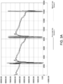
- FIGs. 3A and 3B exemplary plots depicting the psychometric capacity and mass-flow capacity measured during a standard defrosting cycle in a psychometric room (indoor space of the AOI) to determine the amount of heat (in BTU) extracted/absorbed by a typical heat pump (without the modular system 100) from the psychometric room for the defrosting. Further, the calculated amount of heat was observed to calculate the amount of heat that the defrost cycle may draw from the domestic water tank and the drop in temperature in the domestic hot water tank, and further determine how long a de-superheater may take to reheat the water.
- the system 100 when the water in the DHW tank 116 is to be heated in a cooling dominant season or in between heating cycles, the system 100 can be configured to close the solenoid valve 118, open the EXV 120, and then operate the heat pump 108 to enable flow of the refrigerant from the first port 110-1 of the heat pump 108 through the first coil 104 of the RW heat exchanger 102 through conduit C1 while restricting flow of the refrigerant into the fan coil unit 112 (or through conduit C2) as the solenoid valve 118 is closed.
- the system 100 can further actuate the water pump 122 to enable the flow of water from the DHW tank 116 through the second coil 106 of the RW heat exchanger 102 via the water line W1.
- the RW heat exchanger 102 can facilitate heat exchange between the refrigerant flowing through the first coil 104 and the hot water while flowing through the second coil 106 of the RW heat exchanger 102 to heat the water that can be supplied back into the DHW tank 116 via the water line W2.
- the refrigerant can then be supplied back to the heat pump 108 via the refrigerant line R3 and conduit C3.
- the system 100 can be configured to operate the water pump 122 to supply the water from the DHW tank 116 through the second coil 106 of the RW heat exchanger 102 at a maximum flow rate and further operate the heat pump 108 at a minimum (or reduced) heating capacity if the refrigerant is to be fully condensed.
- the system 100 when the AOI is to be cooled, can be configured to open the solenoid valve 118, close the EXV 120, and then operate the heat pump 108 to enable flow of the refrigerant from the first port 110-1 of the heat pump 108 into the inlet 114-1 of the fan coil unit 112 via the refrigerant line R1 (conduit C1 and C2) and further back into the heat pump 108 via the outlet 114-2 of the fan coil unit 112 via the refrigerant line R2 (conduit C3 and C4). Accordingly, the flow of refrigerant through the fan coil unit 112 can facilitate the absorption of heat from the AOI to cool the AOI.
- the process of de-superheating becomes an effective and efficient solution to rapidly reheat DHW (water) following a defrost of the outdoor coil, which may be accomplished within an hour or less.
- This efficient reheat capability enhances the overall responsiveness of the modular system 100.
- the system 100 provides a proactive solution by actively heating the water during off-cycles. As a result, even when the primary demand for heating or cooling at the AOI is reduced, the system 100 remains dynamically engaged in the optimization of the DHW temperature.
- the system 100 can extend the duration of the on-cycle, thereby creating a predetermined interval for an off-cycle. By increasing the heating or cooling capacity during specific periods, the system 100 effectively manages to generate surplus heat energy that can be harnessed during subsequent off-cycles, contributing to enhanced overall efficiency and performance of the modular system 100 and the associated heat pump 108 and fan coil unit 112.
- the system 100 can include a control unit 202 that can be in communication with a controller associated with one or more of the heat pump 108, the water pump 122, the solenoid valve 118, and the EXV 120 via a secured network.
- the control unit 202 can comprise one or more processors 202-1 coupled to a memory 202-2 storing instructions executable by the processors 202-1, which can cause the control unit 202 to perform one or more designated operations.
- the system 100 may further include a thermostat 204 positioned within the AOI.
- the thermostat 204 and/or mobile devices of occupants of the AOI may be in communication with the control unit 202 via the network, which may be configured to enable the occupants of the AOI to set one or more of the first predefined temperature to be maintained within the space of the AOI based on the occupant's comfort and further set the second predefined temperature for the water to be supplied within the AOI by the DHW tank 116.
- the thermostat 204 and/or mobile devices of occupants may further allow the occupants to operate the heat pump 108 in the de-superheating mode, and/or the defrost mode.
- the system 100 can be configured to automatically operate the heat pump 108 in the defrost mode when the system 100 detects an event of frost formation in/on the outdoor coil.
- control unit 202 can be configured to close the EXV 120, open the solenoid valve 118, and actuate the heat pump 108 to adjust the heating capacity of the heat pump 108 and/or flow rate of the refrigerant supplied by the heat pump 108 to the RW heat exchanger 102, and further actuate the water pump 122 to adjust flow rate of the water supplied by the DHW tank 116 to the RW heat exchanger 102, to de-super heat the refrigerant and further heat the water at the second predefined temperature.
- control unit 202 can be configured to open the EXV 120, close the solenoid valve 118, and actuate the heat pump 108 to adjust the heating capacity of the heat pump 108 and/or flow rate of the refrigerant supplied by the heat pump 108 to the RW heat exchanger 102, and further actuate the water pump 122 to adjust the flow rate of the hot water supplied by the DHW tank 116 to the RW heat exchanger 102, to heat the refrigerant and further supply the heated refrigerant to the heat pump 108 to defrost the outdoor coil 110, while restricting the flow of the refrigerant into the fan coil unit 112.
- the control unit 202 can be configured to close the solenoid valve 118, open the EXV 120, and actuate the heat pump 108 to adjust the heating capacity of the heat pump 108 and/or flow rate of the refrigerant supplied by the heat pump 108 to the RW heat exchanger 102, and further actuate the water pump 122 to enable flow of water from the DHW tank 116 through the second coil 106 of the RW heat exchanger 102, to heat the water and further supply the heated water back into the DHW tank 116.
- control unit 202 when the water in the DHW tank 116 is to be heated in the cooling dominant season or in between heating cycles, can be configured to actuate the water pump 122 to supply the water at a maximum flow rate from the DHW tank 116 into the RW heat exchanger 102 and further actuate the heat pump 108 to operate at a minimum heating capacity to fully condense the refrigerant.
- the control unit 202 can be configured to open the solenoid valve 118, close the EXV 120, and operate the heat pump 108 to enable the flow of the refrigerant from the first port 110-1 of the heat pump 108 into the inlet 114-1 of the fan coil unit 112 and further back into the heat pump 108 via the outlet 114-2 of the fan coil unit 112. Accordingly, the flow of refrigerant through the fan coil unit 112 can facilitate the absorption of heat from the AOI to cool and maintain the AOI at the first predefined temperature.
- the modular system utilizes de-superheated heat generated during the heating process to facilitate the warming of the domestic water, which (de-superheating) also makes the fan coil unit's heat exchanger more effective because the system can begin condensing the refrigerant as soon as it gets to the fan coil unit.
- the heat pump functions as a dedicated water heating heat pump that actively raises the temperature of the water without concurrently cooling or providing heating to the indoor environment.
- the heated water resulting from this process serves a dual purpose by being employed as the domestic hot water and also being employed in the defrosting of the outdoor coil. This solution eliminates the need to extract heat from the indoor space of the AOI during defrost cycles, allowing for the utilization of the heat sourced from the domestic water instead, thereby making the overall system efficient and cost-effective.
- this invention overcomes the drawbacks of existing integrated HVAC-DHW systems, by providing a simple, effective, and efficient solution in the form of the modular de-superheater and water heater system.
Landscapes
- Engineering & Computer Science (AREA)
- Mechanical Engineering (AREA)
- General Engineering & Computer Science (AREA)
- Physics & Mathematics (AREA)
- Thermal Sciences (AREA)
- Chemical & Material Sciences (AREA)
- Combustion & Propulsion (AREA)
- Computer Hardware Design (AREA)
- Life Sciences & Earth Sciences (AREA)
- Sustainable Development (AREA)
- Heat-Pump Type And Storage Water Heaters (AREA)
Abstract
A modular de-superheater and water heater system (100). The system comprises a refrigerant-to-water, RW, heat exchanger (102) comprising a first coil (104), and a second coil (106) in thermal communication with each other. A first end (104-1) of the first coil is connected to a first port (110-1) of a heat pump (108) and a second end (104-2) of the first coil is connected to an inlet (114-1) of an indoor fan coil unit (112). A first end (106-1) of the second coil is connected to an outlet (116-1) of a domestic hot water, DHW, tank (116) and a second end (106-2) of the second coil is connected to an inlet (116-2) of the DHW tank. The system further comprises a solenoid valve (118) connected between an outlet (114-2) of the fan coil unit and a second port (110-2) of the heat pump, and an electronic expansion valve (120) connected between the second port of the heat pump and the second end of the first coil.
Description
- This invention relates to the field of de-superheaters and domestic water heating systems, and more particularly, to a modular de-superheater and water heater system.
- According to a first aspect of the invention there is provided a modular de-superheater and water heater system. The system comprises a refrigerant-to-water (RW) heat exchanger comprising a first coil, and a second coil in thermal communication with the first coil to facilitate heat exchange therebetween, wherein a first end of the first coil is configured to be fluidically connected to a first port of a heat pump associated with an outdoor unit and a second end of the first coil is configured to be fluidically connected to an inlet of an indoor fan coil unit associated with an area of interest (AOI), and wherein a first end of the second coil is configured to be fluidically connected to an outlet of a domestic hot water (DHW) tank associated with the AOI and a second end of the second coil is configured to be fluidically connected to an inlet of the DHW tank. The system further comprises a solenoid valve configured to be fluidically connected between an outlet of the fan coil unit and a second port of the heat pump, and an electronic expansion valve (EXV) configured to be fluidically connected between the second port of the heat pump and the second end of the first coil of the RW heat exchanger.
- Optionally, the system comprises a water pump configured to be fluidically connected between the first end of the second coil and an outlet of the DHW tank to control flow of water between the DHW tank and the RW heat exchanger.
- Optionally, the water pump is a variable-speed water pump.
- Optionally, the heat pump is a variable-speed heat pump.
- Optionally, in a de-superheating mode, the system is configured to close the EXV, open the solenoid valve, and operate the heat pump to enable flow of high-temperature, high-pressure vapor phase of the refrigerant from the first port of the heat pump through the first coil of the RW heat exchanger, and further actuate the water pump to enable flow of the water from the DHW tank through the second coil of the RW heat exchanger, wherein the RW heat exchanger facilitates heat exchange between the vapor phase of the refrigerant and the water while flowing therethrough to de-super heat the vapor and further heat the water.
- Optionally, the system is configured to supply the heated water into the DHW tank and the de-superheated vapor into the heat pump via the fan coil unit and the solenoid valve.
- Optionally, when the heat pump is operated in a defrost mode, the system is configured to close the solenoid valve, open the EXV, and operate the heat pump to enable flow of the refrigerant from the second port of the heat pump into the first coil of the RW heat exchanger via the EXV while restricting flow of the refrigerant into the fan coil unit, and further actuate the water pump to enable flow of hot water from the DHW tank through the second coil of the RW heat exchanger, wherein the RW heat exchanger facilitates heat exchange between the refrigerant and the hot water while flowing therethrough to heat the refrigerant.
- Optionally, the system is configured to supply the heated refrigerant into the heat pump via the first port of the heat pump to defrost an outdoor coil associated with the outdoor unit.
- Optionally, when the water in the DHW tank is to be heated in a cooling dominant season or in between heating cycles, the system is configured to close the solenoid valve, open the EXV, and operate the heat pump to enable flow of the refrigerant from the first port of the heat pump through the first coil of the RW heat exchanger while restricting flow of the refrigerant into the fan coil unit, and further actuate the water pump to enable flow of water from the DHW tank through the second coil of the RW heat exchanger, wherein the RW heat exchanger facilitates heat exchange between the refrigerant and the hot water while flowing therethrough to heat the water being supplied back into the DHW tank.
- Optionally, when the water in the DHW tank is to be heated in the cooling dominant season or in between heating cycles, the system can be configured to operate the water pump to supply the water from the DHW tank through the second coil of the RW heat exchanger at a maximum flow rate and the heat pump is operated at a minimum heating capacity.
- Optionally, when the AOI is to be cooled, the system is configured to open the solenoid valve, close the EXV, and operate the heat pump to enable flow of the refrigerant from the first port of the heat pump into the inlet of the fan coil unit and further back into the heat pump via the outlet of the fan coil unit, wherein the flow of refrigerant through the fan coil unit facilitates absorption of heat from the AOI to cool the AOI.
- Optionally, the system comprises a first refrigerant line extending from the first end and the second end of the RW heat exchanger, wherein a first end of the first refrigerant line is configured to be fluidically connected to the first port of the heat pump and a second end of the first refrigerant line is configured to be fluidically connected to the inlet of the fan coil unit, a second refrigerant line extending from an inlet and an outlet of the solenoid valve, wherein a first end of the second refrigerant line is configured to be fluidically connected to the second port of the heat pump and a second end of the second refrigerant line is configured to be fluidically connected to the outlet of the fan coil unit, and a third refrigerant line fluidically connecting the EXV to the first refrigerant line and the second refrigerant line.
- Optionally, the system comprises a first water line having a first end fluidically connected to the second end of the second coil via the water pump and a second end configured to be fluidically connected to the outlet of the DHW tank, and a second water line having a first end fluidically connected to the first end of the second coil and a second end configured to be fluidically connected to the inlet of DHW tank.
- Optionally, the RW heat exchanger, the water pump, the solenoid valve, and the EXV are enclosed within a housing, such that corresponding ends of the first and second refrigeration lines, and the first and second water lines extend out of the housing to facilitate fluidic coupling of the system to the heat pump, the fan coil unit, and the DHW tank.
- Optionally, the first and second refrigeration lines, and the first and second water lines comprise a set of conduits.
- Optionally, the system comprises a control unit in communication with a controller associated with one or more of the heat pump, the water pump, the solenoid valve, and the EXV via a network, wherein the control unit comprises one or more processor coupled to a memory storing instructions executable by the processors, which causes the control unit to: actuate one or more of the heat pump, the water pump, the solenoid valve, and the EXV to control de-superheating of the refrigerant, adjust the temperature of the AOI at a first predefined temperature, heat the water of the DHW tank to a second predefined temperature, and/or control defrosting of the outdoor coil associated with the outdoor unit.
- Optionally, the control unit is configured to close the EXV, open the solenoid valve, and actuate the heat pump to adjust the heating capacity of the heat pump and/or flow rate of the refrigerant supplied by the heat pump to the RW heat exchanger, and further actuate the water pump to adjust flow rate of the water supplied by the DHW tank to the RW heat exchanger, to de-super heat the refrigerant and further heat the water at the second predefined temperature.
- Optionally, the control unit is configured to open the EXV, close the solenoid valve, and actuate the heat pump to adjust the heating capacity of the heat pump and/or flow rate of the refrigerant supplied by the heat pump to the RW heat exchanger, and further actuate the water pump to adjust flow rate of the hot water supplied by the DHW tank to the RW heat exchanger, to heat the refrigerant and further supply the heated refrigerant to the heat pump to defrost the outdoor coil, while restricting flow of the refrigerant into the fan coil unit.
- Optionally, when the water in the DHW tank is to be heated in a cooling dominant season or in between heating cycles, the control unit is configured to close the solenoid valve, open the EXV, and actuate the heat pump to adjust the heating capacity of the heat pump and/or flow rate of the refrigerant supplied by the heat pump to the RW heat exchanger, and further actuate the water pump to enable flow of water from the DHW tank through the second coil of the RW heat exchanger, to heat the water and further supply the heated water back into the DHW tank.
- Optionally, when the water in the DHW tank is to be heated in the cooling dominant season or in between heating cycles, the control unit is configured to actuate the water pump to supply the water at a maximum flow rate from the DHW tank into the RW heat exchanger and further actuate the heat pump to operate at a minimum heating capacity.
- The foregoing summary is illustrative only and is not intended to be in any way limiting. In addition to the illustrative aspects, embodiments, and features described above, further aspects, embodiments, features, and techniques of the invention will become more apparent from the following description taken in conjunction with the drawings.
- The accompanying drawings are included to provide a further understanding of the invention and are incorporated in and constitute a part of this specification. The drawings illustrate exemplary embodiments of the invention and, together with the description, serve to explain the principles of the invention.
- In the drawings, similar components and/or features may have the same reference label. Further, various components of the same type may be distinguished by following the reference label with a second label that distinguishes among the similar components. If only the first reference label is used in the specification, the description is applicable to any one of the similar components having the same first reference label irrespective of the second reference label.
-
FIG. 1 illustrates an exemplary representation of a modular de-superheater and water heater system. -
FIG. 2 illustrates an exemplary control system implemented in the modular de-superheater and water heater system ofFIG. 1 . -
FIGs. 3A and3B illustrate exemplary plots depicting the psychometric capacity and mass-flow capacity measured during a standard defrosting cycle in a psychometric room to determine the amount of heat absorbed from the psychometric room for the defrosting. - The following is a detailed description of embodiments of the invention depicted in the accompanying drawings. The embodiments are in such detail as to clearly communicate the invention. However, the amount of detail offered is not intended to limit the anticipated variations of embodiments; on the contrary, the intention is to cover all modifications, equivalents, and alternatives falling within the scope of the invention as defined by the appended claims.
- Various terms are used herein. To the extent a term used in a claim is not defined below, it should be given the broadest definition persons in the pertinent art have given that term as reflected in printed publications and issued patents at the time of filing.
- In the specification, reference may be made to the spatial relationships between various components and to the spatial orientation of various aspects of components as the devices are depicted in the attached drawings. However, as will be recognized by those skilled in the art after a complete reading of the specification, the components of the invention described herein may be positioned in any desired orientation. Thus, the use of terms such as "above," "below," "upper," "lower," "first", "second" or other like terms to describe a spatial relationship between various components or to describe the spatial orientation of aspects of such components should be understood to describe a relative relationship between the components or a spatial orientation of aspects of such components, respectively, described herein may be oriented in any desired direction.
- In a designated space, a heating, ventilation, and air conditioning (HVAC) system may be installed which may comprise an outdoor heat pump unit and an indoor fan coil unit installed within the space, configured to deliver warm or conditioned air based on occupants' comfort. Additionally, a domestic hot water (DHW) unit may also be integrated to provide hot or warm water within the same space. Notably, the existing systems are engineered to configure the heat pump with both the fan coil unit and the DHW unit, allowing the heat pump to either actively heat the DHW or heat the cooler space at a time. However, the existing configuration restricts the heat pump from concurrently performing both functions.
- Furthermore, the heat pump of existing systems lacks provisions for defrosting, a common issue addressed by conventional systems through the application of electric heaters during defrost cycles or by pulling heat from the space for defrosting. However, the use of resistance heat during these defrosting processes may be expensive and inefficient and may also lead to penalization, adversely affecting the system's overall efficiency. Moreover, pulling heat from the space for defrosting the outdoor coils may make the space cooler or uncomfortable for the occupants. There is therefore a need to overcome the above-mentioned drawbacks, limitations, and shortcomings associated with existing integrated HVAC-DHW systems.
- This invention provides a simple, effective, and efficient solution in the form of a modular de-superheater and water heater system or package that utilizes de-superheated heat generated during the heating process to facilitate the warming of domestic water. The de-superheating also makes the fan coil unit's heat exchanger more effective because the system can begin condensing the refrigerant as soon as it gets to the fan coil unit. In addition, in instances where the system is not engaged in high-capacity heating or lacks adequate de-superheating heat to fully warm the domestic water, the system functions as a dedicated water heating heat pump, actively raising the temperature of the water without concurrently cooling or providing heating to the indoor environment. Furthermore, the heated water resulting from this process serves a dual purpose by also being employed in the defrosting mechanism. This approach eliminates the necessity to extract heat from the indoor environment during defrost cycles, allowing for the utilization of the heat sourced from the domestic water instead, thereby making the overall system efficient and cost-effective.
- Referring to
FIG. 1 , a modular de-superheater and water heater system 100 (also referred to asmodular system 100 orsystem 100, herein) is disclosed. Thesystem 100 can be configured to be connected between aheat pump 108 associated with an outdoor unit and an indoorfan coil unit 112 associated with an area of interest (AOI). In one or more embodiments, theheat pump 108 can be a heat exchanger comprising anoutdoor coil 110 having a first port 110-1 at one end and a second port 110-2 at another end. Theoutdoor coil 110 of theheat pump 108 may be in thermal communication with an ambient to facilitate heat exchange between a refrigerant flowing through theheat pump 108 and the ambient. Further, thefan coil unit 112 can also be a heat exchanger comprising anindoor coil 114 having an inlet 114-1 and an outlet 114-2. Theindoor coil 114 of thefan coil unit 112 may be in thermal communication with an indoor space associated with the AOI where thefan coil unit 112 is installed to facilitate heat exchange between the refrigerant flowing through thefan coil unit 112 and the indoor space. In addition, themodular system 100 can also be configured to be connected to a domestic hot water (DHW)tank 116 associated with the AOI. - In one or more embodiments, the
modular system 100 can include a refrigerant-to-water (RW)heat exchanger 102 comprising afirst coil 104, and asecond coil 106 in thermal communication with thefirst coil 104 to facilitate heat exchange therebetween. A first end 104-1 of thefirst coil 104 of theRW heat exchanger 102 can be configured to be fluidically connected to the first port 110-1 and a second end 104-2 of thefirst coil 104 can be configured to be fluidically connected to the inlet 114-1 of the indoorfan coil unit 112. Further, a first end 106-1 of thesecond coil 106 of theRW heat exchanger 102 can be configured to be fluidically connected to an outlet 116-1 of theDHW tank 116 and a second end 106-2 of thesecond coil 106 can be configured to be fluidically connected to an inlet 116-2 of theDHW tank 116 to enable flow of the water between theDHW tank 116 and thesecond coil 106 of theRW heat exchanger 102. - In addition, in one or more embodiments, the
modular system 100 can include asolenoid valve 118 configured to be fluidically connected between the outlet 114-2 of thefan coil unit 112 and the second port 110-2 of theheat pump 108. Further, themodular system 100 can also include an electronic expansion valve (EXV) 120 that can be configured to be fluidically connected between the second port 110-2 of theheat pump 108 and the second end 104-2 of thefirst coil 104 of theRW heat exchanger 102. - In one or more embodiments, the
modular system 100 can further include awater pump 122 configured to be fluidically connected between the first end 106-1 of thesecond coil 106 and the outlet 116-1 of theDHW tank 116 to control the flow of water between theDHW tank 116 and theRW heat exchanger 102. Thewater pump 122 may be a variable-speed water pump 122; however, thewater pump 122 may also be a fixed-speed pump. - In one or more embodiments, a first refrigerant line R1 comprising a first set of conduits C1, C2 can extend from the first end 104-1 and the second end 104-2 of
first coil 104 of theRW heat exchanger 102, where a first end of the first refrigerant line R1 can be configured to be fluidically connected to the first port 110-1 of theheat pump 108 by a conduit C 1 and a second end of the first refrigerant line R1 can be configured to be fluidically connected to the inlet 114-1 of thefan coil unit 112 by another conduit C2. Further, a second refrigerant line R2 comprising a second set of conduits C3, C4 can extend from an inlet and an outlet of thesolenoid valve 118, where a first end of the second refrigerant line R2 can be configured to be fluidically connected to the second port 110-2 of theheat pump 108 by a conduit C3 and a second end of the second refrigerant line R2 can be configured to be fluidically connected to the outlet 114-2 of thefan coil unit 112 by another conduit C4. In addition, a third refrigerant line R3 comprising a third set of conduits (not designated) can be used to fluidically connect theEXV 120 to the first refrigerant line R1 and the second refrigerant line R2. - In one or more embodiments, a first water line W1 and a second water line W2 can fluidically connect the
DHW tank 116 to thesecond coil 106 of theRW heat exchanger 102. A first end of the first water line W1 can be fluidically connected to the second end 106-2 of thesecond coil 106 via thewater pump 122 and a second end of the first water line W1 can be configured to be fluidically connected to the outlet 116-1 of theDHW tank 116. Further, a first end of the second water line W2 can be fluidically connected to the first end of thesecond coil 106 and a second end of the second water line W2 can be configured to be fluidically connected to the inlet 116-2 of theDHW tank 116. - In one or more embodiments, the
RW heat exchanger 102, thewater pump 122, thesolenoid valve 118, and theEXV 120 associated with thesystem 100 can be enclosed or packaged within ahousing 124 to form a modular structure, such that corresponding ends of the first and second refrigeration lines R1, R2, and the first and second water lines W1, W2 extend out of thehousing 124 to facilitate fluidic coupling of thesystem 100 to theheat pump 108, thefan coil unit 112, and theDHW tank 116. - The
housing 124 or themodular system 100 can be adapted to be installed at a predefined position within the AOI in a horizontal or vertical configuration. Thesystem 100 is designed in a packaged form factor or modular design, where the components/units of thesystem 100 are configured within the housing that is compact and easily installable at a desired location in the AOI/building. The locations can be but are not limited to rooms, entry halls, above doors, below a floor, on the floor, ceiling, walls, corridors, staircases, basement, and storage spaces associated with the building. For instance, the packagedsystem 100/housing 124 can be designed in a horizontal orientation/configuration on each floor above the door in the entry hall or in the corridors, and/or designed in a vertical orientation/ configuration in wet chase risers or at exterior walls, and/or designed to be horizontally or vertically fitted in a closet, and/or configured vertically against the outer wall, but not limited to the like. - In one or more embodiments, in a de-superheating mode, the
system 100 can be configured to close theEXV 120, open thesolenoid valve 118, and then operate theheat pump 108 to enable the flow of high-temperature, high-pressure vapor phase of the refrigerant from the first port 110-1 of theheat pump 108 through thefirst coil 104 of theRW heat exchanger 102 via the refrigerant line R1. Thesystem 100 can further actuate thewater pump 122 to enable the flow of water from theDHW tank 116 through thesecond coil 106 of theRW heat exchanger 102 via the water line W1. Accordingly, theRW heat exchanger 102 can facilitate heat exchange between the vapor phase of the refrigerant and the water while flowing therethrough to de-superheat the vapor and further heat the water. In one or more embodiments, thesystem 100 can be configured to actuate thewater pump 122 to enable the supply of the heated water back into theDHW tank 116 through the water line W2 and further supply the de-superheated vapor back to theheat pump 108 via thefan coil unit 112 and thesolenoid valve 118 through the refrigerant line R2. - In one or more embodiments, when the
heat pump 108 is operated in a defrost mode, thesystem 100 can be configured to close thesolenoid valve 118, open theEXV 120, and then operate theheat pump 108 to enable the flow of the refrigerant from the second port 110-2 of theheat pump 108 into thefirst coil 104 of theRW heat exchanger 102 via theEXV 120 through refrigerant line R2 (conduit C3) and R3 while restricting the flow of the refrigerant into the fan coil unit 112 (or through conduit C4) as thesolenoid valve 118 is closed. TheEXV 120 can enable the expansion of the refrigerant into theRW heat exchanger 102. Thesystem 100 can further actuate thewater pump 122 to enable the flow of hot water from theDHW tank 116 through thesecond coil 106 of theRW heat exchanger 102 via the water line W1. Accordingly, the RW heat exchanger can facilitate heat exchange between the refrigerant flowing through thefirst coil 104 and the hot water while flowing through thesecond coil 106 of theRW heat exchanger 102 to heat the refrigerant. This heated refrigerant can then be supplied into theheat pump 108 via the first port 110-1 of theheat pump 108 through the conduit C 1 to defrost theoutdoor coil 110 associated with the outdoor unit, without using any electric heating or without pulling heat from the indoor space of the AOI. - Referring to
FIGs. 3A and3B , exemplary plots depicting the psychometric capacity and mass-flow capacity measured during a standard defrosting cycle in a psychometric room (indoor space of the AOI) to determine the amount of heat (in BTU) extracted/absorbed by a typical heat pump (without the modular system 100) from the psychometric room for the defrosting. Further, the calculated amount of heat was observed to calculate the amount of heat that the defrost cycle may draw from the domestic water tank and the drop in temperature in the domestic hot water tank, and further determine how long a de-superheater may take to reheat the water. - In one or more embodiments, when the water in the
DHW tank 116 is to be heated in a cooling dominant season or in between heating cycles, thesystem 100 can be configured to close thesolenoid valve 118, open theEXV 120, and then operate theheat pump 108 to enable flow of the refrigerant from the first port 110-1 of theheat pump 108 through thefirst coil 104 of theRW heat exchanger 102 through conduit C1 while restricting flow of the refrigerant into the fan coil unit 112 (or through conduit C2) as thesolenoid valve 118 is closed. Thesystem 100 can further actuate thewater pump 122 to enable the flow of water from theDHW tank 116 through thesecond coil 106 of theRW heat exchanger 102 via the water line W1. Accordingly, theRW heat exchanger 102 can facilitate heat exchange between the refrigerant flowing through thefirst coil 104 and the hot water while flowing through thesecond coil 106 of theRW heat exchanger 102 to heat the water that can be supplied back into theDHW tank 116 via the water line W2. The refrigerant can then be supplied back to theheat pump 108 via the refrigerant line R3 and conduit C3. - In one or more embodiments, when the water in the
DHW tank 116 is to be heated in the cooling dominant season or in between heating cycles, thesystem 100 can be configured to operate thewater pump 122 to supply the water from theDHW tank 116 through thesecond coil 106 of theRW heat exchanger 102 at a maximum flow rate and further operate theheat pump 108 at a minimum (or reduced) heating capacity if the refrigerant is to be fully condensed. - In one or more embodiments, when the AOI is to be cooled, the
system 100 can be configured to open thesolenoid valve 118, close theEXV 120, and then operate theheat pump 108 to enable flow of the refrigerant from the first port 110-1 of theheat pump 108 into the inlet 114-1 of thefan coil unit 112 via the refrigerant line R1 (conduit C1 and C2) and further back into theheat pump 108 via the outlet 114-2 of thefan coil unit 112 via the refrigerant line R2 (conduit C3 and C4). Accordingly, the flow of refrigerant through thefan coil unit 112 can facilitate the absorption of heat from the AOI to cool the AOI. - Accordingly, during periods of elevated heating demand, the process of de-superheating becomes an effective and efficient solution to rapidly reheat DHW (water) following a defrost of the outdoor coil, which may be accomplished within an hour or less. This efficient reheat capability enhances the overall responsiveness of the
modular system 100. Further, in instances where the demand for heating or cooling the DHW is relatively lower, thesystem 100 provides a proactive solution by actively heating the water during off-cycles. As a result, even when the primary demand for heating or cooling at the AOI is reduced, thesystem 100 remains dynamically engaged in the optimization of the DHW temperature. Furthermore, thesystem 100 can extend the duration of the on-cycle, thereby creating a predetermined interval for an off-cycle. By increasing the heating or cooling capacity during specific periods, thesystem 100 effectively manages to generate surplus heat energy that can be harnessed during subsequent off-cycles, contributing to enhanced overall efficiency and performance of themodular system 100 and the associatedheat pump 108 andfan coil unit 112. - Referring to
FIG. 2 , thesystem 100 can include acontrol unit 202 that can be in communication with a controller associated with one or more of theheat pump 108, thewater pump 122, thesolenoid valve 118, and theEXV 120 via a secured network. In one or more embodiments, thecontrol unit 202 can comprise one or more processors 202-1 coupled to a memory 202-2 storing instructions executable by the processors 202-1, which can cause thecontrol unit 202 to perform one or more designated operations. In one or more embodiments, thecontrol unit 202 can actuate one or more of theheat pump 108, thewater pump 122, thesolenoid valve 118, and theEXV 120 to control the de-superheating of the refrigerant, adjust the temperature of the AOI at a first predefined temperature, heat the water of theDHW tank 116 to a second predefined temperature, and/or control defrosting of the outdoor coil associated with the outdoor unit - In one or more embodiments, the
system 100 may further include athermostat 204 positioned within the AOI. Thethermostat 204 and/or mobile devices of occupants of the AOI may be in communication with thecontrol unit 202 via the network, which may be configured to enable the occupants of the AOI to set one or more of the first predefined temperature to be maintained within the space of the AOI based on the occupant's comfort and further set the second predefined temperature for the water to be supplied within the AOI by theDHW tank 116. In one or more embodiments, thethermostat 204 and/or mobile devices of occupants may further allow the occupants to operate theheat pump 108 in the de-superheating mode, and/or the defrost mode. However, thesystem 100 can be configured to automatically operate theheat pump 108 in the defrost mode when thesystem 100 detects an event of frost formation in/on the outdoor coil. - In one or more embodiments, the
control unit 202 can be configured to close theEXV 120, open thesolenoid valve 118, and actuate theheat pump 108 to adjust the heating capacity of theheat pump 108 and/or flow rate of the refrigerant supplied by theheat pump 108 to theRW heat exchanger 102, and further actuate thewater pump 122 to adjust flow rate of the water supplied by theDHW tank 116 to theRW heat exchanger 102, to de-super heat the refrigerant and further heat the water at the second predefined temperature. - In one or more embodiments, the
control unit 202 can be configured to open theEXV 120, close thesolenoid valve 118, and actuate theheat pump 108 to adjust the heating capacity of theheat pump 108 and/or flow rate of the refrigerant supplied by theheat pump 108 to theRW heat exchanger 102, and further actuate thewater pump 122 to adjust the flow rate of the hot water supplied by theDHW tank 116 to theRW heat exchanger 102, to heat the refrigerant and further supply the heated refrigerant to theheat pump 108 to defrost theoutdoor coil 110, while restricting the flow of the refrigerant into thefan coil unit 112. - In one or more embodiments, when the water in the
DHW tank 116 is to be heated in a cooling dominant season or in between heating cycles, thecontrol unit 202 can be configured to close thesolenoid valve 118, open theEXV 120, and actuate theheat pump 108 to adjust the heating capacity of theheat pump 108 and/or flow rate of the refrigerant supplied by theheat pump 108 to theRW heat exchanger 102, and further actuate thewater pump 122 to enable flow of water from theDHW tank 116 through thesecond coil 106 of theRW heat exchanger 102, to heat the water and further supply the heated water back into theDHW tank 116. - In one or more embodiments, when the water in the
DHW tank 116 is to be heated in the cooling dominant season or in between heating cycles, thecontrol unit 202 can be configured to actuate thewater pump 122 to supply the water at a maximum flow rate from theDHW tank 116 into theRW heat exchanger 102 and further actuate theheat pump 108 to operate at a minimum heating capacity to fully condense the refrigerant. - In one or more embodiments, wherein when the AOI is to be cooled or maintained at the first predefined temperature, the
control unit 202 can be configured to open thesolenoid valve 118, close theEXV 120, and operate theheat pump 108 to enable the flow of the refrigerant from the first port 110-1 of theheat pump 108 into the inlet 114-1 of thefan coil unit 112 and further back into theheat pump 108 via the outlet 114-2 of thefan coil unit 112. Accordingly, the flow of refrigerant through thefan coil unit 112 can facilitate the absorption of heat from the AOI to cool and maintain the AOI at the first predefined temperature. - It is to be appreciated by a person skilled in the art that the modular system utilizes de-superheated heat generated during the heating process to facilitate the warming of the domestic water, which (de-superheating) also makes the fan coil unit's heat exchanger more effective because the system can begin condensing the refrigerant as soon as it gets to the fan coil unit. In addition, in instances where the system is not engaged in high-capacity heating or lacks adequate de-superheating heat to fully warm the domestic water, the heat pump functions as a dedicated water heating heat pump that actively raises the temperature of the water without concurrently cooling or providing heating to the indoor environment. In addition, the heated water resulting from this process serves a dual purpose by being employed as the domestic hot water and also being employed in the defrosting of the outdoor coil. This solution eliminates the need to extract heat from the indoor space of the AOI during defrost cycles, allowing for the utilization of the heat sourced from the domestic water instead, thereby making the overall system efficient and cost-effective.
- Thus, this invention overcomes the drawbacks of existing integrated HVAC-DHW systems, by providing a simple, effective, and efficient solution in the form of the modular de-superheater and water heater system.
- While the invention has been described with reference to exemplary embodiments, it will be understood by those skilled in the art that various changes may be made and equivalents may be substituted for elements thereof without departing from the scope of the invention as defined by the appended claims. Modifications may be made to adopt a particular situation or material to the teachings of the invention without departing from the scope thereof as defined by the appended claims. Therefore, it is intended that the invention not be limited to the particular embodiment disclosed, but that the invention includes all embodiments falling within the scope of the invention as defined by the appended claims.
- In interpreting the specification, all terms should be interpreted in the broadest possible manner consistent with the context. In particular, the terms "comprises" and "comprising" should be interpreted as referring to elements, components, or steps in a non-exclusive manner, indicating that the referenced elements, components, or steps may be present, or utilized, or combined with other elements, components, or steps that are not expressly referenced. Where the specification claims refer to at least one of something selected from the group consisting of A, B, C ....and N, the text should be interpreted as requiring only one element from the group, not A plus N, or B plus N, etc.
- The following clauses set out features of the invention which may not presently be claimed in this application, but which may form the basis for future amendment and/or a divisional application.
- 1. A modular de-superheater and water heater system, the system comprising:
- a refrigerant-to-water (RW) heat exchanger comprising a first coil, and a second coil in thermal communication with the first coil to facilitate heat exchange therebetween,
- wherein a first end of the first coil is configured to be fluidically connected to a first port of a heat pump associated with an outdoor unit and a second end of the first coil is configured to be fluidically connected to an inlet of an indoor fan coil unit associated with an area of interest (AOI), and
- wherein a first end of the second coil is configured to be fluidically connected to an outlet of a domestic hot water (DHW) tank associated with the AOI and a second end of the second coil is configured to be fluidically connected to an inlet of the DHW tank;
- a solenoid valve configured to be fluidically connected between an outlet of the fan coil unit and a second port of the heat pump; and
- an electronic expansion valve (EXV) configured to be fluidically connected between the second port of the heat pump and the second end of the first coil of the RW heat exchanger.
- 2. The system of clause 1, wherein the system comprises a water pump configured to be fluidically connected between the first end of the second coil and an outlet of the DHW tank to control flow of water between the DHW tank and the RW heat exchanger.
- 3. The system of clause 2, wherein the water pump is a variable-speed water pump.
- 4. The system of any one of clauses 1 to 3, wherein the heat pump is a variable-speed heat pump.
- 5. The system of any one of clauses 1 to 4, wherein in a de-superheating mode, the system is configured to close the EXV, open the solenoid valve, and operate the heat pump to enable flow of high-temperature, high-pressure vapor phase of the refrigerant from the first port of the heat pump through the first coil of the RW heat exchanger, and further actuate the water pump to enable flow of water from the DHW tank through the second coil of the RW heat exchanger, wherein the RW heat exchanger facilitates heat exchange between the vapor phase of the refrigerant and the water while flowing therethrough to de-super heat the vapor and further heat the water.
- 6. The system of clause 5, wherein the system is configured to supply the heated water into the DHW tank and the de-superheated vapor into the heat pump via the fan coil unit and the solenoid valve.
- 7. The system of any one of clauses 1 to 4, wherein when the heat pump is operated in a defrost mode, the system is configured to close the solenoid valve, open the EXV, and operate the heat pump to enable flow of the refrigerant from the second port of the heat pump into the first coil of the RW heat exchanger via the EXV while restricting flow of the refrigerant into the fan coil unit, and further actuate the water pump to enable flow of hot water from the DHW tank through the second coil of the RW heat exchanger, wherein the RW heat exchanger facilitates heat exchange between the refrigerant and the hot water while flowing therethrough to heat the refrigerant.
- 8. The system of clause 7, wherein the system is configured to supply the heated refrigerant into the heat pump via the first port of the heat pump to defrost an outdoor coil associated with the outdoor unit.
- 9. The system of any one of clauses 1 to 4, wherein when the water in the DHW tank is to be heated in a cooling dominant season or in between heating cycles, the system is configured to close the solenoid valve, open the EXV, and operate the heat pump to enable flow of the refrigerant from the first port of the heat pump through the first coil of the RW heat exchanger while restricting flow of the refrigerant into the fan coil unit, and further actuate the water pump to enable flow of water from the DHW tank through the second coil of the RW heat exchanger, wherein the RW heat exchanger facilitates heat exchange between the refrigerant and the hot water while flowing therethrough to heat the water being supplied back into the DHW tank.
- 10. The system of clause 9, wherein when the water in the DHW tank is to be heated in the cooling dominant season or in between heating cycles, the system can be configured to operate the water pump to supply the water from the DHW tank through the second coil of the RW heat exchanger at a maximum flow rate and the heat pump is operated at a minimum heating capacity.
- 11. The system of any one of clauses 1 to 4, wherein when the AOI is to be cooled, the system is configured to open the solenoid valve, close the EXV, and operate the heat pump to enable flow of the refrigerant from the first port of the heat pump into the inlet of the fan coil unit and further back into the heat pump via the outlet of the fan coil unit, wherein the flow of refrigerant through the fan coil unit facilitates absorption of heat from the AOI to cool the AOI.
- 12. The system of any one of clauses 1 to 11, wherein the system comprises:
- a first refrigerant line extending from the first end and the second end of the RW heat exchanger, wherein a first end of the first refrigerant line is configured to be fluidically connected to the first port of the heat pump and a second end of the first refrigerant line is configured to be fluidically connected to the inlet of the fan coil unit;
- a second refrigerant line extending from an inlet and an outlet of the solenoid valve, wherein a first end of the second refrigerant line is configured to be fluidically connected to the second port of the heat pump and a second end of the second refrigerant line is configured to be fluidically connected to the outlet of the fan coil unit; and
- a third refrigerant line fluidically connecting the EXV to the first refrigerant line and the second refrigerant line;
- 13. The system of any one of clauses 1 to 12, wherein the system comprises:
- a first water line having a first end fluidically connected to the second end of the second coil via the water pump and a second end configured to be fluidically connected to the outlet of the DHW tank; and
- a second water line having a first end fluidically connected to the first end of the second coil and a second end configured to be fluidically connected to the inlet of DHW tank.
- 14. The system of any one of clauses 1 to 13, wherein the RW heat exchanger, the water pump, the solenoid valve, and the EXV are enclosed within a housing, such that corresponding ends of the first and second refrigeration lines, and the first and second water lines extend out of the housing to facilitate fluidic coupling of the system to the heat pump, the fan coil unit, and the DHW tank.
- 15. The system of any one of clauses 12 and 13, wherein the first and second refrigeration lines, and the first and second water lines comprise a set of conduits.
- 16. The system of any one of clauses 1 to 15, wherein the system comprises a control unit in communication with a controller associated with one or more of the heat pump, the water pump, the solenoid valve, and the EXV via a network, wherein the control unit comprises one or more processor coupled to a memory storing instructions executable by the processors, which causes the control unit to:
actuate one or more of the heat pump, the water pump, the solenoid valve, and the EXV to control the de-superheating of the refrigerant, adjust the temperature of the AOI at a first predefined temperature, heat the water of the DHW tank to a second predefined temperature, and/or control defrosting of the outdoor coil associated with the outdoor unit. - 17. The system of clause 16, wherein the control unit is configured to close the EXV, open the solenoid valve, and actuate the heat pump to adjust the heating capacity of the heat pump and/or flow rate of the refrigerant supplied by the heat pump to the RW heat exchanger, and further actuate the water pump to adjust flow rate of the water supplied by the DHW tank to the RW heat exchanger, to de-super heat the refrigerant and further heat the water at the second predefined temperature.
- 18. The system of clause 16, wherein the control unit is configured to open the EXV, close the solenoid valve, and actuate the heat pump to adjust the heating capacity of the heat pump and/or flow rate of the refrigerant supplied by the heat pump to the RW heat exchanger, and further actuate the water pump to adjust flow rate of the hot water supplied by the DHW tank to the RW heat exchanger, to heat the refrigerant and further supply the heated refrigerant to the heat pump to defrost the outdoor coil, while restricting flow of the refrigerant into the fan coil unit.
- 19. The system of clause 16, wherein when the water in the DHW tank is to be heated in a cooling dominant season or in between heating cycles, the control unit is configured to close the solenoid valve, open the EXV, and actuate the heat pump to adjust the heating capacity of the heat pump and/or flow rate of the refrigerant supplied by the heat pump to the RW heat exchanger, and further actuate the water pump to enable flow of water from the DHW tank through the second coil of the RW heat exchanger, to heat the water and further supply the heated water back into the DHW tank.
- 20. The system of clause 19, wherein when the water in the DHW tank is to be heated in the cooling dominant season or in between heating cycles, the control unit is configured to actuate the water pump to supply the water at a maximum flow rate from the DHW tank into the RW heat exchanger and further actuate the heat pump to operate at a minimum heating capacity.
Claims (15)
- A modular de-superheater and water heater system (100), the system comprising:
a refrigerant-to-water, RW, heat exchanger (102) comprising a first coil (104), and a second coil (106) in thermal communication with the first coil to facilitate heat exchange therebetween,wherein a first end (104-1) of the first coil is configured to be fluidically connected to a first port (110-1) of a heat pump (108) associated with an outdoor unit and a second end (104-2) of the first coil is configured to be fluidically connected to an inlet (114-1) of an indoor fan coil unit (112) associated with an area of interest, AOI, andwherein a first end (106-1) of the second coil is configured to be fluidically connected to an outlet (116-1) of a domestic hot water, DHW, tank (116) associated with the AOI and a second end (106-2) of the second coil is configured to be fluidically connected to an inlet (116-2) of the DHW tank;a solenoid valve (118) configured to be fluidically connected between an outlet (114-2) of the fan coil unit and a second port (110-2) of the heat pump; andan electronic expansion valve, EXV, (120) configured to be fluidically connected between the second port of the heat pump and the second end of the first coil of the RW heat exchanger. - The system of claim 1, wherein the heat pump is a variable-speed heat pump.
- The system of claim 1 or 2, wherein the system comprises a water pump (122) configured to be fluidically connected between the first end of the second coil and the outlet of the DHW tank to control flow of water between the DHW tank and the RW heat exchanger;
optionally, wherein the water pump is a variable-speed water pump. - The system of claim 3, wherein in a de-superheating mode, the system is configured to close the EXV, open the solenoid valve, and operate the heat pump to enable flow of high-temperature, high-pressure vapor phase of the refrigerant from the first port of the heat pump through the first coil of the RW heat exchanger, and further actuate the water pump to enable flow of water from the DHW tank through the second coil of the RW heat exchanger, wherein the RW heat exchanger facilitates heat exchange between the vapor phase of the refrigerant and the water while flowing therethrough to de-super heat the vapor and further heat the water;
optionally, wherein the system is configured to supply the heated water into the DHW tank and the de-superheated vapor into the heat pump via the fan coil unit and the solenoid valve. - The system of claim 3 or 4, wherein when the heat pump is operated in a defrost mode, the system is configured to close the solenoid valve, open the EXV, and operate the heat pump to enable flow of the refrigerant from the second port of the heat pump into the first coil of the RW heat exchanger via the EXV while restricting flow of the refrigerant into the fan coil unit, and further actuate the water pump to enable flow of hot water from the DHW tank through the second coil of the RW heat exchanger, wherein the RW heat exchanger facilitates heat exchange between the refrigerant and the hot water while flowing therethrough to heat the refrigerant;
optionally, wherein the system is configured to supply the heated refrigerant into the heat pump via the first port of the heat pump to defrost an outdoor coil associated with the outdoor unit. - The system of any of claims 3 to 5, wherein when the water in the DHW tank is to be heated in a cooling dominant season or in between heating cycles, the system is configured to close the solenoid valve, open the EXV, and operate the heat pump to enable flow of the refrigerant from the first port of the heat pump through the first coil of the RW heat exchanger while restricting flow of the refrigerant into the fan coil unit, and further actuate the water pump to enable flow of water from the DHW tank through the second coil of the RW heat exchanger, wherein the RW heat exchanger facilitates heat exchange between the refrigerant and the hot water while flowing therethrough to heat the water being supplied back into the DHW tank;
and/or, wherein when the water in the DHW tank is to be heated in the cooling dominant season or in between heating cycles, the system can be configured to operate the water pump to supply the water from the DHW tank through the second coil of the RW heat exchanger at a maximum flow rate and the heat pump is operated at a minimum heating capacity. - The system of any of claims 3 to 6, wherein the system comprises:a first water line (W1) having a first end fluidically connected to the second end of the second coil via the water pump and a second end configured to be fluidically connected to the outlet of the DHW tank; anda second water line (W2) having a first end fluidically connected to the first end of the second coil and a second end configured to be fluidically connected to the inlet of the DHW tank.
- The system of any of claims 3 to 7, wherein the system comprises a control unit (202) in communication with a controller associated with one or more of the heat pump, the water pump, the solenoid valve, and the EXV via a network, wherein the control unit comprises one or more processors (202-1) coupled to a memory (202-2) storing instructions executable by the processors, which causes the control unit to:
actuate one or more of the heat pump, the water pump, the solenoid valve, and the EXV to control the de-superheating of the refrigerant, adjust the temperature of the AOI at a first predefined temperature, heat the water of the DHW tank to a second predefined temperature, and/or control defrosting of the outdoor coil associated with the outdoor unit. - The system of claim 8, wherein the control unit is configured to close the EXV, open the solenoid valve, and actuate the heat pump to adjust the heating capacity of the heat pump and/or flow rate of the refrigerant supplied by the heat pump to the RW heat exchanger, and further actuate the water pump to adjust flow rate of the water supplied by the DHW tank to the RW heat exchanger, to de-super heat the refrigerant and further heat the water at the second predefined temperature.
- The system of claim 8 or 9, wherein the control unit is configured to open the EXV, close the solenoid valve, and actuate the heat pump to adjust the heating capacity of the heat pump and/or flow rate of the refrigerant supplied by the heat pump to the RW heat exchanger, and further actuate the water pump to adjust flow rate of the hot water supplied by the DHW tank to the RW heat exchanger, to heat the refrigerant and further supply the heated refrigerant to the heat pump to defrost the outdoor coil, while restricting flow of the refrigerant into the fan coil unit.
- The system of any of claims 8 to 10, wherein when the water in the DHW tank is to be heated in a cooling dominant season or in between heating cycles, the control unit is configured to close the solenoid valve, open the EXV, and actuate the heat pump to adjust the heating capacity of the heat pump and/or flow rate of the refrigerant supplied by the heat pump to the RW heat exchanger, and further actuate the water pump to enable flow of water from the DHW tank through the second coil of the RW heat exchanger, to heat the water and further supply the heated water back into the DHW tank;
and/or wherein when the water in the DHW tank is to be heated in the cooling dominant season or in between heating cycles, the control unit is configured to actuate the water pump to supply the water at a maximum flow rate from the DHW tank into the RW heat exchanger and further actuate the heat pump to operate at a minimum heating capacity. - The system of any preceding claim, wherein when the AOI is to be cooled, the system is configured to open the solenoid valve, close the EXV, and operate the heat pump to enable flow of the refrigerant from the first port of the heat pump into the inlet of the fan coil unit and further back into the heat pump via the outlet of the fan coil unit, wherein the flow of refrigerant through the fan coil unit facilitates absorption of heat from the AOI to cool the AOI.
- The system of any preceding claim, wherein the system comprises:a first refrigerant line extending from the first end and the second end of the RW heat exchanger, wherein a first end of the first refrigerant line is configured to be fluidically connected to the first port of the heat pump and a second end of the first refrigerant line is configured to be fluidically connected to the inlet of the fan coil unit;a second refrigerant line extending from an inlet and an outlet of the solenoid valve, wherein a first end of the second refrigerant line is configured to be fluidically connected to the second port of the heat pump and a second end of the second refrigerant line is configured to be fluidically connected to the outlet of the fan coil unit; anda third refrigerant line fluidically connecting the EXV to the first refrigerant line and the second refrigerant line.
- The system of claim 13 when dependent on claim 7 or when dependent on any of claims 8 to 12 when dependent on claim 7, wherein the RW heat exchanger, the water pump, the solenoid valve, and the EXV are enclosed within a housing (124), such that corresponding ends of the first and second refrigerant lines, and the first and second water lines extend out of the housing to facilitate fluidic coupling of the system to the heat pump, the fan coil unit, and the DHW tank.
- The system of claim 13 when dependent on claim 7 or when dependent on any of claims 8 to 12 when dependent on claim 7, or the system of claim 14, wherein the first and second refrigerant lines, and the first and second water lines comprise a set of conduits (C1, C2, C3, C4).
Applications Claiming Priority (1)
| Application Number | Priority Date | Filing Date | Title |
|---|---|---|---|
| US202363609900P | 2023-12-14 | 2023-12-14 |
Publications (1)
| Publication Number | Publication Date |
|---|---|
| EP4575328A1 true EP4575328A1 (en) | 2025-06-25 |
Family
ID=93843572
Family Applications (1)
| Application Number | Title | Priority Date | Filing Date |
|---|---|---|---|
| EP24218486.9A Pending EP4575328A1 (en) | 2023-12-14 | 2024-12-09 | A modular de-superheater and water heater system |
Country Status (2)
| Country | Link |
|---|---|
| US (1) | US20250198672A1 (en) |
| EP (1) | EP4575328A1 (en) |
Citations (5)
| Publication number | Priority date | Publication date | Assignee | Title |
|---|---|---|---|---|
| US20110259025A1 (en) * | 2010-04-22 | 2011-10-27 | Lg Electronics Inc. | Heat pump type speed heating apparatus |
| WO2011149152A1 (en) * | 2010-05-28 | 2011-12-01 | Lg Electronics Inc. | Hot water supply device associated with heat pump |
| US20170211862A1 (en) * | 2016-01-25 | 2017-07-27 | Sharp Kabushiki Kaisha | Dual temperature heat pump system |
| EP1767879B1 (en) * | 2004-04-28 | 2017-09-20 | Toshiba Carrier Corporation | Heat pump-type hot water supply apparatus |
| US10823471B2 (en) * | 2018-05-23 | 2020-11-03 | Carrier Corporation | Refrigerant transfer control in multi mode air conditioner with hot water generator |
-
2024
- 2024-12-06 US US18/971,101 patent/US20250198672A1/en active Pending
- 2024-12-09 EP EP24218486.9A patent/EP4575328A1/en active Pending
Patent Citations (5)
| Publication number | Priority date | Publication date | Assignee | Title |
|---|---|---|---|---|
| EP1767879B1 (en) * | 2004-04-28 | 2017-09-20 | Toshiba Carrier Corporation | Heat pump-type hot water supply apparatus |
| US20110259025A1 (en) * | 2010-04-22 | 2011-10-27 | Lg Electronics Inc. | Heat pump type speed heating apparatus |
| WO2011149152A1 (en) * | 2010-05-28 | 2011-12-01 | Lg Electronics Inc. | Hot water supply device associated with heat pump |
| US20170211862A1 (en) * | 2016-01-25 | 2017-07-27 | Sharp Kabushiki Kaisha | Dual temperature heat pump system |
| US10823471B2 (en) * | 2018-05-23 | 2020-11-03 | Carrier Corporation | Refrigerant transfer control in multi mode air conditioner with hot water generator |
Also Published As
| Publication number | Publication date |
|---|---|
| US20250198672A1 (en) | 2025-06-19 |
Similar Documents
| Publication | Publication Date | Title |
|---|---|---|
| US20220178566A1 (en) | Hydronic building systems control | |
| US8122944B2 (en) | Combined potable water-surface heating and cooling system | |
| JPWO2008152786A1 (en) | Residential water heater | |
| CN105783121A (en) | Cabinet air conditioner system | |
| CN110579036A (en) | A multi-connected hot and cold water system and its control method | |
| JP2008281319A (en) | Air-conditioning outdoor unit connection type cold / hot water floor air conditioning unit | |
| US10612792B2 (en) | Air conditioning system, peripheral air-conditioning unit thereof and water pipeline upgrading method for heating purposes | |
| US20250198672A1 (en) | Modular de-superheater and water heater system | |
| EP2224189B1 (en) | Water circulation system associated with refrigerant cycle | |
| EP4372287A2 (en) | Modular hvac-shw/dhw system and a method of integrating thereof | |
| JP4110843B2 (en) | AIR CONDITIONER, AIR CONDITIONER INSTALLATION METHOD | |
| JP2012225596A (en) | Heat pump system for heating | |
| WO2002048618A1 (en) | Cooling and heating system using jointly the radient with convection | |
| US20160033145A1 (en) | Room-to-Room Heat Pump | |
| JP6111871B2 (en) | Demand response system | |
| CN104214864A (en) | Energy-saving air conditioner hot water system | |
| Bhatia | HVAC variable refrigerant flow systems | |
| JP2003056905A (en) | Water heater | |
| JPH02166351A (en) | Heat pump type cooling, heating and hot water supply device | |
| Cox | Heating, ventilating and air conditioning systems | |
| EP4624821A1 (en) | A building comprising an interior space having a plurality of rooms | |
| WO2004068036A1 (en) | An integrated fire protection system and cooling system | |
| CN115031318A (en) | Multifunctional air conditioner with water heater | |
| Bhatia | Design Options for HVAC Distribution Systems | |
| Rafferty | Space Heating Equipment |
Legal Events
| Date | Code | Title | Description |
|---|---|---|---|
| PUAI | Public reference made under article 153(3) epc to a published international application that has entered the european phase |
Free format text: ORIGINAL CODE: 0009012 |
|
| STAA | Information on the status of an ep patent application or granted ep patent |
Free format text: STATUS: THE APPLICATION HAS BEEN PUBLISHED |
|
| AK | Designated contracting states |
Kind code of ref document: A1 Designated state(s): AL AT BE BG CH CY CZ DE DK EE ES FI FR GB GR HR HU IE IS IT LI LT LU LV MC ME MK MT NL NO PL PT RO RS SE SI SK SM TR |
|
| STAA | Information on the status of an ep patent application or granted ep patent |
Free format text: STATUS: REQUEST FOR EXAMINATION WAS MADE |
|
| 17P | Request for examination filed |
Effective date: 20251223 |