EP4575264A1 - Two-gear driving assembly and new energy vehicle - Google Patents
Two-gear driving assembly and new energy vehicle Download PDFInfo
- Publication number
- EP4575264A1 EP4575264A1 EP23945619.7A EP23945619A EP4575264A1 EP 4575264 A1 EP4575264 A1 EP 4575264A1 EP 23945619 A EP23945619 A EP 23945619A EP 4575264 A1 EP4575264 A1 EP 4575264A1
- Authority
- EP
- European Patent Office
- Prior art keywords
- gear
- shaft
- transmission
- output shaft
- clutch
- Prior art date
- Legal status (The legal status is an assumption and is not a legal conclusion. Google has not performed a legal analysis and makes no representation as to the accuracy of the status listed.)
- Pending
Links
Images
Classifications
-
- F—MECHANICAL ENGINEERING; LIGHTING; HEATING; WEAPONS; BLASTING
- F16—ENGINEERING ELEMENTS AND UNITS; GENERAL MEASURES FOR PRODUCING AND MAINTAINING EFFECTIVE FUNCTIONING OF MACHINES OR INSTALLATIONS; THERMAL INSULATION IN GENERAL
- F16H—GEARING
- F16H3/00—Toothed gearings for conveying rotary motion with variable gear ratio or for reversing rotary motion
- F16H3/02—Toothed gearings for conveying rotary motion with variable gear ratio or for reversing rotary motion without gears having orbital motion
- F16H3/08—Toothed gearings for conveying rotary motion with variable gear ratio or for reversing rotary motion without gears having orbital motion exclusively or essentially with continuously meshing gears, that can be disengaged from their shafts
- F16H3/087—Toothed gearings for conveying rotary motion with variable gear ratio or for reversing rotary motion without gears having orbital motion exclusively or essentially with continuously meshing gears, that can be disengaged from their shafts characterised by the disposition of the gears
-
- B—PERFORMING OPERATIONS; TRANSPORTING
- B60—VEHICLES IN GENERAL
- B60K—ARRANGEMENT OR MOUNTING OF PROPULSION UNITS OR OF TRANSMISSIONS IN VEHICLES; ARRANGEMENT OR MOUNTING OF PLURAL DIVERSE PRIME-MOVERS IN VEHICLES; AUXILIARY DRIVES FOR VEHICLES; INSTRUMENTATION OR DASHBOARDS FOR VEHICLES; ARRANGEMENTS IN CONNECTION WITH COOLING, AIR INTAKE, GAS EXHAUST OR FUEL SUPPLY OF PROPULSION UNITS IN VEHICLES
- B60K17/00—Arrangement or mounting of transmissions in vehicles
- B60K17/04—Arrangement or mounting of transmissions in vehicles characterised by arrangement, location or kind of gearing
- B60K17/16—Arrangement or mounting of transmissions in vehicles characterised by arrangement, location or kind of gearing of differential gearing
-
- B—PERFORMING OPERATIONS; TRANSPORTING
- B60—VEHICLES IN GENERAL
- B60K—ARRANGEMENT OR MOUNTING OF PROPULSION UNITS OR OF TRANSMISSIONS IN VEHICLES; ARRANGEMENT OR MOUNTING OF PLURAL DIVERSE PRIME-MOVERS IN VEHICLES; AUXILIARY DRIVES FOR VEHICLES; INSTRUMENTATION OR DASHBOARDS FOR VEHICLES; ARRANGEMENTS IN CONNECTION WITH COOLING, AIR INTAKE, GAS EXHAUST OR FUEL SUPPLY OF PROPULSION UNITS IN VEHICLES
- B60K17/00—Arrangement or mounting of transmissions in vehicles
- B60K17/04—Arrangement or mounting of transmissions in vehicles characterised by arrangement, location or kind of gearing
- B60K17/06—Arrangement or mounting of transmissions in vehicles characterised by arrangement, location or kind of gearing of change-speed gearing
-
- F—MECHANICAL ENGINEERING; LIGHTING; HEATING; WEAPONS; BLASTING
- F16—ENGINEERING ELEMENTS AND UNITS; GENERAL MEASURES FOR PRODUCING AND MAINTAINING EFFECTIVE FUNCTIONING OF MACHINES OR INSTALLATIONS; THERMAL INSULATION IN GENERAL
- F16H—GEARING
- F16H1/00—Toothed gearings for conveying rotary motion
- F16H1/28—Toothed gearings for conveying rotary motion with gears having orbital motion
- F16H1/32—Toothed gearings for conveying rotary motion with gears having orbital motion in which the central axis of the gearing lies inside the periphery of an orbital gear
-
- F—MECHANICAL ENGINEERING; LIGHTING; HEATING; WEAPONS; BLASTING
- F16—ENGINEERING ELEMENTS AND UNITS; GENERAL MEASURES FOR PRODUCING AND MAINTAINING EFFECTIVE FUNCTIONING OF MACHINES OR INSTALLATIONS; THERMAL INSULATION IN GENERAL
- F16H—GEARING
- F16H3/00—Toothed gearings for conveying rotary motion with variable gear ratio or for reversing rotary motion
- F16H3/02—Toothed gearings for conveying rotary motion with variable gear ratio or for reversing rotary motion without gears having orbital motion
- F16H3/08—Toothed gearings for conveying rotary motion with variable gear ratio or for reversing rotary motion without gears having orbital motion exclusively or essentially with continuously meshing gears, that can be disengaged from their shafts
- F16H3/087—Toothed gearings for conveying rotary motion with variable gear ratio or for reversing rotary motion without gears having orbital motion exclusively or essentially with continuously meshing gears, that can be disengaged from their shafts characterised by the disposition of the gears
- F16H3/091—Toothed gearings for conveying rotary motion with variable gear ratio or for reversing rotary motion without gears having orbital motion exclusively or essentially with continuously meshing gears, that can be disengaged from their shafts characterised by the disposition of the gears including a single countershaft
-
- F—MECHANICAL ENGINEERING; LIGHTING; HEATING; WEAPONS; BLASTING
- F16—ENGINEERING ELEMENTS AND UNITS; GENERAL MEASURES FOR PRODUCING AND MAINTAINING EFFECTIVE FUNCTIONING OF MACHINES OR INSTALLATIONS; THERMAL INSULATION IN GENERAL
- F16H—GEARING
- F16H37/00—Combinations of mechanical gearings, not provided for in groups F16H1/00 - F16H35/00
- F16H37/02—Combinations of mechanical gearings, not provided for in groups F16H1/00 - F16H35/00 comprising essentially only toothed or friction gearings
- F16H37/04—Combinations of toothed gearings only
- F16H37/042—Combinations of toothed gearings only change gear transmissions in group arrangement
-
- F—MECHANICAL ENGINEERING; LIGHTING; HEATING; WEAPONS; BLASTING
- F16—ENGINEERING ELEMENTS AND UNITS; GENERAL MEASURES FOR PRODUCING AND MAINTAINING EFFECTIVE FUNCTIONING OF MACHINES OR INSTALLATIONS; THERMAL INSULATION IN GENERAL
- F16H—GEARING
- F16H57/00—General details of gearing
- F16H57/02—Gearboxes; Mounting gearing therein
- F16H57/021—Shaft support structures, e.g. partition walls, bearing eyes, casing walls or covers with bearings
-
- F—MECHANICAL ENGINEERING; LIGHTING; HEATING; WEAPONS; BLASTING
- F16—ENGINEERING ELEMENTS AND UNITS; GENERAL MEASURES FOR PRODUCING AND MAINTAINING EFFECTIVE FUNCTIONING OF MACHINES OR INSTALLATIONS; THERMAL INSULATION IN GENERAL
- F16H—GEARING
- F16H57/00—General details of gearing
- F16H57/08—General details of gearing of gearings with members having orbital motion
- F16H57/082—Planet carriers
-
- F—MECHANICAL ENGINEERING; LIGHTING; HEATING; WEAPONS; BLASTING
- F16—ENGINEERING ELEMENTS AND UNITS; GENERAL MEASURES FOR PRODUCING AND MAINTAINING EFFECTIVE FUNCTIONING OF MACHINES OR INSTALLATIONS; THERMAL INSULATION IN GENERAL
- F16H—GEARING
- F16H2200/00—Transmissions for multiple ratios
- F16H2200/0021—Transmissions for multiple ratios specially adapted for electric vehicles
-
- F—MECHANICAL ENGINEERING; LIGHTING; HEATING; WEAPONS; BLASTING
- F16—ENGINEERING ELEMENTS AND UNITS; GENERAL MEASURES FOR PRODUCING AND MAINTAINING EFFECTIVE FUNCTIONING OF MACHINES OR INSTALLATIONS; THERMAL INSULATION IN GENERAL
- F16H—GEARING
- F16H2200/00—Transmissions for multiple ratios
- F16H2200/003—Transmissions for multiple ratios characterised by the number of forward speeds
- F16H2200/0034—Transmissions for multiple ratios characterised by the number of forward speeds the gear ratios comprising two forward speeds
Definitions
- the present disclosure belongs to the technical field of new energy vehicles, and specifically relates to a two-speed drive assembly and a new energy vehicle.
- the drive assembly of a new energy vehicle is generally composed of a motor and a reducer.
- the motor first converts electrical energy into mechanical energy to provide power for the vehicle, and then reduces the motor speed by the reducer while amplifying the output torque of the motor, thereby achieving the effect of decreasing the speed and increasing the torque, so that the drive assembly can operate within a certain rotational speed range and under a certain driving torque.
- the drive assemblies in new energy vehicles mostly use a motor and a reducer with a fixed gear ratio.
- the motor speed should be adjustable within a large range.
- a large power motor needs to be selected to match with the whole vehicle, which increases the production cost of the drive assembly.
- a reducer with a fixed gear ratio is used to match with the motor, when the vehicle is running at low speed or high speed, the vehicle speed can be adjusted only by adjusting the motor speed.
- the output torque and power of the motor are required to be high when the vehicle is running at low speed or starting, and the maximum motor speed is required to be high when the vehicle is running at high speed.
- the high-speed operation of the motor will bring about many problems such as those of NVH (Noise, Vibration, Harshness), sealing and durability.
- the present disclosure discloses a two-speed drive assembly and a new energy vehicle to overcome or at least partially solve the above problems.
- An aspect of the present disclosure provides a two-speed drive assembly, comprising: a drive source, a transmission mechanism and a reduction mechanism;
- an output shaft of the drive source and the input shaft of the transmission mechanism are an integrated structure.
- the output shaft is a hollow shaft, and is sleeved on an output half shaft on a side of the differential.
- the reduction mechanism comprises a sun gear, a planetary gear, a ring gear and a planetary carrier; the sun gear is sleeved on the output shaft, the ring gear is coaxially sleeved on an outer side of the sun gear, the planetary gear is arranged between the sun gear and the ring gear and is respectively meshed with the sun gear and the ring gear, the planetary gear is connected to the planetary carrier via a planetary shaft, and the planetary carrier is connected to a housing of the differential.
- the planetary carrier and the housing of the differential are an integrated structure.
- the third gear and the intermediate shaft are connected for transmission via a first clutch, and a first needle bearing is provided between the third gear and the intermediate shaft; the sixth gear and the output shaft are connected for transmission via a second clutch, and a second needle bearing is provided between the sixth gear and the output shaft.
- connection between the first gear and the input shaft, between the second gear and the intermediate shaft, between the fourth gear and the intermediate shaft, and between the fifth gear and the output shaft are all by splines.
- the fifth gear and the output shaft are connected for transmission via a first clutch, and a first needle bearing is provided between the fifth gear and the output shaft; the sixth gear and the output shaft are connected for transmission via a second clutch, and a second needle bearing is provided between the sixth gear and the output shaft.
- a third clutch is provided between the housing of the differential and an output half shaft on a side of the differential.
- Another aspect of the present disclosure provides a new energy vehicle, which uses the two-speed drive assembly as described above.
- the two-speed drive assembly of the present disclosure by providing the input shaft, the intermediate shaft and the output shaft that are arranged in parallel, a two-stage speed reduction at two gear positions with different gear ratios is realized; moreover, by providing a reduction mechanism between the output shaft and the differential, the two-speed drive assembly can output power with a high transmission ratio, and the requirements for the power, torque and maximum speed of the motor are reduced while the requirements of the maximum speed and power of the vehicle can be satisfied, thereby reducing the cost of the two-speed electric drive assembly and avoiding the NVH, sealing and durability problems caused by the high-speed operation of the motor.
- the two-speed drive assembly has advantages such as large output torque, compact structure, small space occupation, high transmission efficiency, good NVH performance and low production cost.
- a two-speed drive assembly is disclosed in this embodiment. As shown in FIGS. 1 and 2 , the two-speed drive assembly comprises a drive source 1, a transmission mechanism and a reduction mechanism.
- the drive source may be an electric motor or an engine.
- the transmission mechanism comprises an input shaft 2, an intermediate shaft 3 and an output shaft 4 that are arranged in parallel.
- the input shaft 2 is connected to the driving source 1 for transmission.
- the input shaft 2 is provided thereon with a first gear 5.
- the intermediate shaft 3 is provided thereon with a second gear 6, a third gear 7 and a fourth gear 8.
- the output shaft 4 is provided thereon with a fifth gear 9 and a sixth gear 10.
- the first gear 5 and the second gear 6 are meshed for transmission
- the third gear 7 and the fifth gear 9 are meshed for transmission
- the fourth gear 8 and the sixth gear 10 are meshed for transmission.
- the third gear 7 and the intermediate shaft 3 are transmission connected via a first clutch 16, and a first needle bearing 17 is provided between the third gear 7 and the intermediate shaft 3.
- the transmission ratio of the third gear 7 and the fifth gear 9 is different from the transmission ratio of the fourth gear 8 and the sixth gear 10, and two speed ratio outputs are realized. That is, by controlling the first clutch 16 and the second clutch 18, the intermediate shaft 3 and the output shaft 4 can be meshed for transmission via the third gear 7 and the fifth gear 9 or via the fourth gear 8 and the sixth gear 10, thereby realizing the switching of low speed gear and high speed gear, and further satisfying different working conditions.
- the output shaft 4 is a hollow shaft, and is sleeved on the left output half shaft 21 on the left side of the differential 11, so that the output shaft 4 can rotate relative to the left output half shaft 21 while maintaining relatively stationary in the axial direction.
- the output shaft may be sleeved on the right output half shaft on the right side of the differential, which is also within the protection scope of the present disclosure.
- the power on the output shaft 4 is transmitted to the housing of the differential 11 via the sun gear 12, the planetary gear 13 and the planetary carrier 15 in sequence, and the two-speed drive assembly can achieve a large torque output by controlling the transmission ratio of the planetary gear 13 and the sun gear 12.
- the planetary carrier and the housing of the differential are integrally manufactured and formed, which is convenient for the assembly of the two-speed drive assembly and makes the connection structure between the planetary carrier and the housing of the differential simpler and firmer.
- the planetary carrier and the housing of the differential may be separate structures, which are processed and manufactured separately, and then fixedly connected by screw/bolt connection or welding. The separate planetary carrier and housing of the differential are easier to manufacture and process.
Landscapes
- Engineering & Computer Science (AREA)
- General Engineering & Computer Science (AREA)
- Mechanical Engineering (AREA)
- Chemical & Material Sciences (AREA)
- Combustion & Propulsion (AREA)
- Transportation (AREA)
- Structure Of Transmissions (AREA)
- Retarders (AREA)
Abstract
Description
- This application claims priority to the
Chinese patent application No. 202310880041.3 filed with the Chinese Patent Office on July 18, 2023 - The present disclosure belongs to the technical field of new energy vehicles, and specifically relates to a two-speed drive assembly and a new energy vehicle.
- The drive assembly of a new energy vehicle is generally composed of a motor and a reducer. The motor first converts electrical energy into mechanical energy to provide power for the vehicle, and then reduces the motor speed by the reducer while amplifying the output torque of the motor, thereby achieving the effect of decreasing the speed and increasing the torque, so that the drive assembly can operate within a certain rotational speed range and under a certain driving torque.
- At present, the drive assemblies in new energy vehicles mostly use a motor and a reducer with a fixed gear ratio. In order to meet the maximum speed requirement of the whole vehicle, the motor speed should be adjustable within a large range. In order to meet the power requirement of the vehicle, a large power motor needs to be selected to match with the whole vehicle, which increases the production cost of the drive assembly. Moreover, if a reducer with a fixed gear ratio is used to match with the motor, when the vehicle is running at low speed or high speed, the vehicle speed can be adjusted only by adjusting the motor speed. Thus, the output torque and power of the motor are required to be high when the vehicle is running at low speed or starting, and the maximum motor speed is required to be high when the vehicle is running at high speed. The high-speed operation of the motor will bring about many problems such as those of NVH (Noise, Vibration, Harshness), sealing and durability.
- In view of the above problems, the present disclosure discloses a two-speed drive assembly and a new energy vehicle to overcome or at least partially solve the above problems.
- In order to achieve the above object, the present disclosure adopts the following technical solutions.
- An aspect of the present disclosure provides a two-speed drive assembly, comprising: a drive source, a transmission mechanism and a reduction mechanism;
- the transmission mechanism comprises an input shaft, an intermediate shaft and an output shaft that are arranged in parallel, the input shaft is connected to the drive source for transmission, the input shaft is provided thereon with a first gear, the intermediate shaft is provided thereon with a second gear, a third gear and a fourth gear, the output shaft is provided thereon with a fifth gear and a sixth gear, the first gear and the second gear are meshed for transmission, the third gear and the fifth gear are meshed for transmission, the fourth gear and the sixth gear are meshed for transmission, the third gear and the intermediate shaft are connected for transmission via a clutch or the fifth gear and the output shaft are connected for transmission via a clutch, the fourth gear and the intermediate shaft are connected for transmission via a clutch or the sixth gear and the output shaft are connected for transmission via a clutch;
- the reduction mechanism is sleeved on the output shaft and connected to the differential for transmission.
- Further, an output shaft of the drive source and the input shaft of the transmission mechanism are an integrated structure.
- Further, the output shaft is a hollow shaft, and is sleeved on an output half shaft on a side of the differential.
- Further, the reduction mechanism comprises a sun gear, a planetary gear, a ring gear and a planetary carrier;
the sun gear is sleeved on the output shaft, the ring gear is coaxially sleeved on an outer side of the sun gear, the planetary gear is arranged between the sun gear and the ring gear and is respectively meshed with the sun gear and the ring gear, the planetary gear is connected to the planetary carrier via a planetary shaft, and the planetary carrier is connected to a housing of the differential. - Further, the planetary carrier and the housing of the differential are an integrated structure.
- Further, the third gear and the intermediate shaft are connected for transmission via a first clutch, and a first needle bearing is provided between the third gear and the intermediate shaft; the sixth gear and the output shaft are connected for transmission via a second clutch, and a second needle bearing is provided between the sixth gear and the output shaft.
- Further, the connection between the first gear and the input shaft, between the second gear and the intermediate shaft, between the fourth gear and the intermediate shaft, and between the fifth gear and the output shaft are all by splines.
- Further, the fifth gear and the output shaft are connected for transmission via a first clutch, and a first needle bearing is provided between the fifth gear and the output shaft; the sixth gear and the output shaft are connected for transmission via a second clutch, and a second needle bearing is provided between the sixth gear and the output shaft.
- Further, a third clutch is provided between the housing of the differential and an output half shaft on a side of the differential.
- Another aspect of the present disclosure provides a new energy vehicle, which uses the two-speed drive assembly as described above.
- The advantages and beneficial effects of the present disclosure are as follows.
- In the two-speed drive assembly of the present disclosure, by providing the input shaft, the intermediate shaft and the output shaft that are arranged in parallel, a two-stage speed reduction at two gear positions with different gear ratios is realized; moreover, by providing a reduction mechanism between the output shaft and the differential, the two-speed drive assembly can output power with a high transmission ratio, and the requirements for the power, torque and maximum speed of the motor are reduced while the requirements of the maximum speed and power of the vehicle can be satisfied, thereby reducing the cost of the two-speed electric drive assembly and avoiding the NVH, sealing and durability problems caused by the high-speed operation of the motor. The two-speed drive assembly has advantages such as large output torque, compact structure, small space occupation, high transmission efficiency, good NVH performance and low production cost.
- By reading the detailed description of the preferred embodiments below, various other advantages and benefits will become clear to a person of ordinary skill in the art. The accompanying drawings are only used for the purpose of illustrating the preferred embodiments, and should not be considered as a limitation to the present disclosure. Moreover, throughout the drawings, the same reference numerals are used to denote the same components. In the drawings:
-
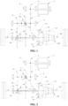
FIG. 1 is a schematic view of the structure of a two-speed drive assembly at a first gear position in an embodiment of the present disclosure; and -
FIG. 2 is a schematic view of the structure of a two-speed drive assembly at a second gear position in an embodiment of the present disclosure. - In the drawings: 1, drive source; 2, input shaft; 3, intermediate shaft; 4, output shaft; 5, first gear; 6, second gear; 7, third gear; 8, fourth gear; 9, fifth gear; 10, sixth gear; 11, differential; 12, sun gear; 13, planetary gear; 14, ring gear; 15, planetary carrier; 16, first clutch; 17, first needle bearing; 18, second clutch; 19, second needle bearing; 20, third clutch; 21, left output half shaft; 22, right output half shaft.
- In order to make the object, technical solutions, and advantages of the present disclosure clearer, the present disclosure will be described clearly and completely in conjunction with the specific embodiments and corresponding drawings. Obviously, the embodiments described are only part of rather than all of the embodiments of the present disclosure. Based on the embodiments in the present disclosure, all other embodiments obtained by those of ordinary skill in the art without paying creative work shall fall within the protection scope of the present disclosure.
- The technical solutions provided by various embodiments of the present disclosure will be described in detail with reference to the accompanying drawings.
- A two-speed drive assembly is disclosed in this embodiment. As shown in
FIGS. 1 and 2 , the two-speed drive assembly comprises adrive source 1, a transmission mechanism and a reduction mechanism. The drive source may be an electric motor or an engine. - Specifically, the transmission mechanism comprises an
input shaft 2, an intermediate shaft 3 and an output shaft 4 that are arranged in parallel. Theinput shaft 2 is connected to thedriving source 1 for transmission. Theinput shaft 2 is provided thereon with afirst gear 5. The intermediate shaft 3 is provided thereon with asecond gear 6, athird gear 7 and afourth gear 8. The output shaft 4 is provided thereon with afifth gear 9 and asixth gear 10. Thefirst gear 5 and thesecond gear 6 are meshed for transmission, thethird gear 7 and thefifth gear 9 are meshed for transmission, and thefourth gear 8 and thesixth gear 10 are meshed for transmission. Thethird gear 7 and the intermediate shaft 3 are transmission connected via afirst clutch 16, and a first needle bearing 17 is provided between thethird gear 7 and the intermediate shaft 3. Thesixth gear 10 and the output shaft 4 are transmission connected via asecond clutch 18, and a second needle bearing 19 is provided between thesixth gear 10 and the output shaft 4. Moreover, the connection between thefirst gear 5 and theinput shaft 2, thesecond gear 6 and the intermediate shaft 3, thefourth gear 8 and the intermediate shaft 3, and thefifth gear 9 and the output shaft 4 are all by splines. - The transmission ratio of the
third gear 7 and thefifth gear 9 is different from the transmission ratio of thefourth gear 8 and thesixth gear 10, and two speed ratio outputs are realized. That is, by controlling thefirst clutch 16 and thesecond clutch 18, the intermediate shaft 3 and the output shaft 4 can be meshed for transmission via thethird gear 7 and thefifth gear 9 or via thefourth gear 8 and thesixth gear 10, thereby realizing the switching of low speed gear and high speed gear, and further satisfying different working conditions. Moreover, the transmission of theinput shaft 2 and the intermediate shaft 3 is realized by the meshing of thefirst gear 5 and thesecond gear 6, and the transmission of the intermediate shaft 3 and the output shaft 4 is realized by the meshing of thethird gear 7 and thefifth gear 9 or the meshing of thefourth gear 8 and thesixth gear 10, and thus two-stage speed reduction can be achieved. - In addition, the reduction mechanism is sleeved on the output shaft 4 and is connected to a
differential 11 for transmission, and the power is transmitted to a leftoutput half shaft 21 and a rightoutput half shaft 22 via thedifferential 11, thereby driving the wheels to rotate and realizing power output. - In the two-speed drive assembly of this embodiment, by providing the input shaft, the intermediate shaft and the output shaft that are arranged in parallel, a two-stage speed reduction at two gear positions with different gear ratios is realized; moreover, by providing a reduction mechanism between the output shaft and the differential, the two-speed drive assembly can output power with a high transmission ratio, and the requirements for the power, torque and maximum speed of the motor are reduced while the requirements of the maximum speed and power of the vehicle can be satisfied, thereby reducing the cost of the two-speed electric drive assembly and avoiding the NVH, sealing and durability problems caused by the high-speed operation of the motor. The two-speed drive assembly has advantages such as large output torque, compact structure, small space occupation, high transmission efficiency, good NVH performance and low production cost.
- In this embodiment, an output shaft of the drive source and the input shaft of the transmission mechanism are an integrated structure, so that when the power is transmitted, the impact of the output shaft of the drive source on the transmission mechanism can be reduced, and the transmission loss can be reduced. In other embodiments of the present disclosure, alternatively, the output shaft of the drive source may be connected to the input shaft of the transmission mechanism via a coupling.
- In addition, as shown in
FIGS. 1 and 2 , the output shaft 4 is a hollow shaft, and is sleeved on the leftoutput half shaft 21 on the left side of the differential 11, so that the output shaft 4 can rotate relative to the leftoutput half shaft 21 while maintaining relatively stationary in the axial direction. Of course, alternatively, the output shaft may be sleeved on the right output half shaft on the right side of the differential, which is also within the protection scope of the present disclosure. By designing that the output shaft is sleeved on the output half shaft on a side of the differential, the original space of the differential can be fully utilized, so that the longitudinal volume of the two-speed drive assembly when it cooperates with the differential is smaller. - Further, the reduction mechanism comprises a
sun gear 12, aplanetary gear 13, aring gear 14 and aplanetary carrier 15. - Specifically, the
sun gear 12 is sleeved on the output shaft 4; thering gear 14 is coaxially sleeved on the outside of thesun gear 12, and can be fixedly connected to the housing of the transmission mechanism; theplanetary gear 13 is arranged between thesun gear 12 and thering gear 14, and meshes with thesun gear 12 and thering gear 14 respectively, theplanetary gear 13 is connected to theplanetary carrier 15 via the planetary shaft, and theplanetary carrier 15 is connected to the housing of the differential 11. In this way, the power on the output shaft 4 is transmitted to the housing of the differential 11 via thesun gear 12, theplanetary gear 13 and theplanetary carrier 15 in sequence, and the two-speed drive assembly can achieve a large torque output by controlling the transmission ratio of theplanetary gear 13 and thesun gear 12. There are multiple, preferably three or four, planetary gears. - Moreover, the planetary carrier and the housing of the differential are integrally manufactured and formed, which is convenient for the assembly of the two-speed drive assembly and makes the connection structure between the planetary carrier and the housing of the differential simpler and firmer. Of course, in other embodiments, alternatively, the planetary carrier and the housing of the differential may be separate structures, which are processed and manufactured separately, and then fixedly connected by screw/bolt connection or welding. The separate planetary carrier and housing of the differential are easier to manufacture and process.
- In addition, a third clutch 20 is provided between the housing of the differential 11 and the right
output half shaft 22 on the right side of the differential 11. When the third clutch 20 is engaged, the housing of the differential 11 and the rightoutput half shaft 22 are locked, thereby realizing the locking of the differential 11. In this way, when a wheel on one side slips or cannot contact the road surface, the differential can be locked by the third clutch, so that the power is transmitted to the wheels that have adhesion to the road surface, thereby getting the car off trouble. Of course, alternatively, the third clutch may be provided between the housing of the differential and the left output half shaft. - The specific working process of the two-speed drive assembly in this embodiment is as follows.
- The implementation process at the first gear position is as follows. As shown in
FIG. 1 , the first clutch 16 is controlled to disengage, and the second clutch 18 is controlled to engage. At this point, the power is generated by the drivingsource 1 and transmitted to thefirst gear 5 via theinput shaft 2. Thefirst gear 5 is meshed with thesecond gear 6 to transmit the power to the intermediate shaft 3, thereby realizing a first-stage speed reduction. The intermediate shaft 3 drives thefourth gear 8 to rotate, and thefourth gear 8 is meshed with thesixth gear 10 to transmit the power to the output shaft 4, thereby realizing a second-stage speed reduction. The output shaft 4 transmits the power to theplanetary carrier 15 via thesun gear 12 and theplanetary gear 13 in sequence, thereby realizing planetary speed reduction and torque increase. Theplanetary carrier 15 drives the housing of the differential 11 to rotate, and the power is transmitted to the wheels via theleft output axle 21 and theright output axle 22, thereby realizing the driving state at the first gear position. - The implementation process at the second gear position is as follows. As shown in
FIG. 2 , the first clutch 16 is controlled to engage, and the second clutch 18 is controlled to disengage. At this point, the power is generated by the drivingsource 1 and transmitted to thefirst gear 5 via theinput shaft 2. Thefirst gear 5 is meshed with thesecond gear 6 to transmit the power to the intermediate shaft 3, thereby realizing a first-stage speed reduction. The intermediate shaft 3 drives thethird gear 7 to rotate, and thethird gear 7 is meshed with thefifth gear 9 to transmit the power to the output shaft 4, thereby realizing a second-stage speed reduction. The output shaft 4 transmits the power to theplanetary carrier 15 via thesun gear 12 and theplanetary gear 13 in sequence, thereby realizing planetary speed reduction and torque increase. Theplanetary carrier 15 drives the housing of the differential 11 to rotate, and the power is transmitted to the wheels via the leftoutput half shaft 21 and the rightoutput half shaft 22, thereby realizing the driving state at the second gear position. - This embodiment differs from the first embodiment in that, the fifth gear is connected to the output shaft for transmission via the first clutch, and a first needle bearing is provided between the fifth gear and the output shaft; the sixth gear is connected to the output shaft for transmission via the second clutch, and a second needle bearing is provided between the sixth gear and the output shaft. In this way, when the two-speed drive assembly is idling, the load of the drive source can be reduced and energy consumption can be reduced.
- Of course, in other embodiments, alternatively, the third gear and the intermediate shaft may be connected for transmission via the first clutch, and the fourth gear and the intermediate shaft may be connected for transmission via the second clutch.
- This embodiment discloses a new energy vehicle, which uses the two-speed drive assembly in the above embodiments, and has advantages such as sufficient output power, low production cost and good NVH performance.
- The above merely describes particular embodiments of the present disclosure. By the teaching of the present disclosure, a person skilled in the art can make other modifications or variations based on the above embodiments. A person skilled in the art should appreciate that, the detailed description above is only for the purpose of explaining the present disclosure, and the protection scope of the present disclosure should be subject to the protection scope of the claims.
Claims (10)
- A two-speed drive assembly, comprising:a drive source (1), a transmission mechanism and a reduction mechanism;characterized in that: the transmission mechanism comprises an input shaft (2), an intermediate shaft (3) and an output shaft (4) that are arranged in parallel, the input shaft (2) is connected to the drive source (1) for transmission, the input shaft (2) is provided thereon with a first gear (5), the intermediate shaft (3) is provided thereon with a second gear (6), a third gear (7) and a fourth gear (8), the output shaft (4) is provided thereon with a fifth gear (9) and a sixth gear (10), the first gear (5) and the second gear (6) are meshed for transmission, the third gear (7) and the fifth gear (9) are meshed for transmission, the fourth gear (8) and the sixth gear (10) are meshed for transmission, the third gear (7) and the intermediate shaft (3) are connected for transmission via a clutch or the fifth gear (9) and the output shaft (4) are connected for transmission via a clutch, the fourth gear (8) and the intermediate shaft (3) are connected for transmission via a clutch or the sixth gear (10) and the output shaft (4) are connected for transmission via a clutch;the reduction mechanism is sleeved on the output shaft (4) and connected to a differential (11) for transmission.
- The two-speed drive assembly according to claim 1, characterized in that: an output shaft (4) of the drive source (1) and the input shaft (2) of the transmission mechanism are an integrated structure.
- The two-speed drive assembly according to claim 1, characterized in that: the output shaft (4) is a hollow shaft, and is sleeved on an output half shaft on a side of the differential (11).
- The two-speed drive assembly according to claim 3, characterized in that: the reduction mechanism comprises a sun gear (12), a planetary gear (13), a ring gear (14) and a planetary carrier (15);
the sun gear (12) is sleeved on the output shaft (4), the ring gear (14) is coaxially sleeved on an outer side of the sun gear (12), the planetary gear (13) is arranged between the sun gear (12) and the ring gear (14) and is respectively meshed with the sun gear (12) and the ring gear (14), the planetary gear (13) is connected to the planetary carrier (15) via a planetary shaft, and the planetary carrier (15) is connected to a housing of the differential (11). - The two-speed drive assembly according to claim 4, characterized in that: the planetary carrier (15) and the housing of the differential (11) are an integrated structure.
- The two-speed drive assembly according to claim 1, characterized in that: the third gear (7) and the intermediate shaft (3) are connected for transmission via a first clutch (16), and a first needle bearing (17) is provided between the third gear (7) and the intermediate shaft (3); the sixth gear (10) and the output shaft (4) are connected for transmission via a second clutch (18), and a second needle bearing (19) is provided between the sixth gear (10) and the output shaft (4).
- The two-speed drive assembly according to claim 6, characterized in that: the connection between the first gear (5) and the input shaft (2), between the second gear (6) and the intermediate shaft (3), between the fourth gear (8) and the intermediate shaft (3), and between the fifth gear (9) and the output shaft (4) are all by splines.
- The two-speed drive assembly according to claim 1, characterized in that: the fifth gear (9) and the output shaft (4) are connected for transmission via a first clutch (16), and a first needle bearing (17) is provided between the fifth gear (9) and the output shaft (4); the sixth gear (10) and the output shaft (4) are connected for transmission via a second clutch (18), and a second needle bearing (19) is provided between the sixth gear (10) and the output shaft (4).
- The two-speed drive assembly according to any one of claims 1 to 8, characterized in that: a third clutch (20) is provided between a housing of the differential (11) and an output half shaft on a side of the differential (11).
- A new energy vehicle using the two-speed drive assembly according to any one of claims 1 to 9.
Applications Claiming Priority (2)
| Application Number | Priority Date | Filing Date | Title |
|---|---|---|---|
| CN202310880041.3A CN116658579A (en) | 2023-07-18 | 2023-07-18 | A two-speed drive assembly and a new energy vehicle |
| PCT/CN2023/126714 WO2025015738A1 (en) | 2023-07-18 | 2023-10-26 | Two-gear driving assembly and new energy vehicle |
Publications (2)
| Publication Number | Publication Date |
|---|---|
| EP4575264A1 true EP4575264A1 (en) | 2025-06-25 |
| EP4575264A4 EP4575264A4 (en) | 2025-08-06 |
Family
ID=87715459
Family Applications (1)
| Application Number | Title | Priority Date | Filing Date |
|---|---|---|---|
| EP23945619.7A Pending EP4575264A4 (en) | 2023-07-18 | 2023-10-26 | TWO-SPEED DRIVELINE AND NEW ENERGY VEHICLE |
Country Status (3)
| Country | Link |
|---|---|
| EP (1) | EP4575264A4 (en) |
| CN (1) | CN116658579A (en) |
| WO (1) | WO2025015738A1 (en) |
Families Citing this family (1)
| Publication number | Priority date | Publication date | Assignee | Title |
|---|---|---|---|---|
| CN116658579A (en) * | 2023-07-18 | 2023-08-29 | 精进电动科技股份有限公司 | A two-speed drive assembly and a new energy vehicle |
Family Cites Families (27)
| Publication number | Priority date | Publication date | Assignee | Title |
|---|---|---|---|---|
| US9303745B2 (en) * | 2010-12-23 | 2016-04-05 | Magna Powertrain Inc. | Multi-speed transaxle for electric and hybrid vehicle application |
| WO2015149874A1 (en) * | 2014-04-04 | 2015-10-08 | Gkn Driveline International Gmbh | Drive arrangement for a motor vehicle |
| KR101640312B1 (en) * | 2014-10-31 | 2016-07-15 | 현대위아 주식회사 | Two-speed transmission for electric vehicle |
| US10221928B2 (en) * | 2015-12-18 | 2019-03-05 | Musashi Seimitsu Industry Co., Ltd. | Differential device |
| EP3165790A1 (en) * | 2016-04-04 | 2017-05-10 | AVL List GmbH | Multi-speed transmission and method for operating a multi-speed transmission |
| CN205780686U (en) * | 2016-04-23 | 2016-12-07 | 中国第一汽车股份有限公司 | A kind of integrated drive device of two grades of electric automobiles |
| JP2017197107A (en) * | 2016-04-28 | 2017-11-02 | 平岩 一美 | Automobile driving device |
| DE102017127146B3 (en) * | 2017-11-17 | 2019-03-14 | Gkn Automotive Ltd. | Manual transmission and electric drive with a manual transmission |
| DE102018203458B4 (en) * | 2018-03-07 | 2019-10-17 | Audi Ag | Drive device for an electrically operated vehicle |
| KR102554881B1 (en) * | 2018-04-11 | 2023-07-12 | 현대자동차주식회사 | Transmission for electric vehicle |
| DE102018111798A1 (en) * | 2018-05-16 | 2019-11-21 | Schaeffler Technologies AG & Co. KG | Drive device with an electric machine |
| WO2019241773A1 (en) * | 2018-06-15 | 2019-12-19 | Dana Automotive Systems Group, Llc | Multi-speed gearbox with high torque ratio and the drive axle made therewith |
| KR20200005338A (en) * | 2018-07-06 | 2020-01-15 | 현대자동차주식회사 | Transmission for electric vehicle |
| DE102018120276A1 (en) * | 2018-08-21 | 2020-02-27 | Schaeffler Technologies AG & Co. KG | gear unit |
| DE102019206075A1 (en) * | 2019-04-29 | 2020-10-29 | Zf Friedrichshafen Ag | Travel drive system for work machine |
| US11148526B2 (en) * | 2020-02-19 | 2021-10-19 | Dana Automotive Systems Group, Llc | Electric drive axle gear train and method for manufacturing said gear train |
| US20230243417A1 (en) * | 2020-07-30 | 2023-08-03 | Aisin Aw Co., Ltd. | Control device |
| JP2022036678A (en) * | 2020-08-24 | 2022-03-08 | いすゞ自動車株式会社 | Hydraulic drive unit and vehicle |
| JP2022045146A (en) * | 2020-09-08 | 2022-03-18 | 株式会社アイシン | Vehicular driving device |
| CN112706597A (en) * | 2021-01-12 | 2021-04-27 | 中国重汽集团济南动力有限公司 | Double-motor electric drive axle |
| CN113775708A (en) * | 2021-08-04 | 2021-12-10 | 一汽奔腾轿车有限公司 | An automatic shift two-speed reducer matching new energy pure electric vehicle |
| CN113978224A (en) * | 2021-11-16 | 2022-01-28 | 江苏华永复合材料有限公司 | Double-motor double-gear electric drive axle |
| CN114516268A (en) * | 2022-03-23 | 2022-05-20 | 精进电动科技股份有限公司 | Transverse driving assembly |
| CN116176173A (en) * | 2023-03-20 | 2023-05-30 | 北京京深深向科技有限公司 | Multi-gear electric drive axle configuration and vehicle with dual-motor alternate gear shifting |
| CN116373596B (en) * | 2023-04-20 | 2026-04-10 | 江苏华永复合材料有限公司 | High-efficiency four-speed electric drive axle transmission system |
| CN116278687B (en) * | 2023-05-26 | 2023-09-22 | 江苏速豹动力科技有限公司 | Electric axles and electric trucks |
| CN116658579A (en) * | 2023-07-18 | 2023-08-29 | 精进电动科技股份有限公司 | A two-speed drive assembly and a new energy vehicle |
-
2023
- 2023-07-18 CN CN202310880041.3A patent/CN116658579A/en active Pending
- 2023-10-26 EP EP23945619.7A patent/EP4575264A4/en active Pending
- 2023-10-26 WO PCT/CN2023/126714 patent/WO2025015738A1/en active Pending
Also Published As
| Publication number | Publication date |
|---|---|
| CN116658579A (en) | 2023-08-29 |
| EP4575264A4 (en) | 2025-08-06 |
| WO2025015738A1 (en) | 2025-01-23 |
Similar Documents
| Publication | Publication Date | Title |
|---|---|---|
| CN218777398U (en) | Three-gear electric drive bridge structure | |
| US12539749B2 (en) | Drive synthesis box with multi-motors flexible torque and electric vehicle | |
| CN103692907B (en) | A kind of power system assembly of electronlmobil | |
| CN115534646B (en) | Electric drivetrains, four-wheel drive systems and automobiles | |
| CN210852020U (en) | Electric vehicle drive system and electric drive axle, electric vehicle | |
| CN113276600A (en) | Coaxial two-gear electric drive axle | |
| CN110654219B (en) | Wheel limit actuating system and vehicle that has it | |
| CN218777413U (en) | Electric drive bridge structure driven by single motor | |
| CN113085541A (en) | Two-gear high-speed electric drive system for automobile | |
| CN115962268A (en) | Speed reducer, control method thereof and electric off-road vehicle with speed reducer | |
| CN117565651A (en) | Electric axles and electric trucks | |
| JP7760606B2 (en) | Electric drive assembly, four-wheel drive system and automobile | |
| EP4579101A1 (en) | Longitudinal two-gear electric drive assembly and new energy vehicle | |
| EP4575264A1 (en) | Two-gear driving assembly and new energy vehicle | |
| CN111791694A (en) | Coaxial two-speed drive system | |
| CN116674374A (en) | A vehicle and its variable speed ratio drive axle | |
| CN219821209U (en) | Vehicle and variable-ratio drive axle thereof | |
| AU2023358399B2 (en) | Electric drive gearbox of construction machine | |
| CN218858157U (en) | Drive assembly and vehicle | |
| CN111853179A (en) | A two-speed reducer device and vehicle | |
| CN218489458U (en) | Coaxial double-motor electric drive axle system for heavy truck | |
| CN216666382U (en) | Two keep off gear drive | |
| CN118457187A (en) | Vehicle driving system and vehicle | |
| CN216895588U (en) | High-low speed shaft transmission rear axle with gear shifting function | |
| CN214404550U (en) | Reduction gear and vehicle |
Legal Events
| Date | Code | Title | Description |
|---|---|---|---|
| STAA | Information on the status of an ep patent application or granted ep patent |
Free format text: STATUS: THE INTERNATIONAL PUBLICATION HAS BEEN MADE |
|
| PUAI | Public reference made under article 153(3) epc to a published international application that has entered the european phase |
Free format text: ORIGINAL CODE: 0009012 |
|
| STAA | Information on the status of an ep patent application or granted ep patent |
Free format text: STATUS: REQUEST FOR EXAMINATION WAS MADE |
|
| 17P | Request for examination filed |
Effective date: 20250317 |
|
| AK | Designated contracting states |
Kind code of ref document: A1 Designated state(s): AL AT BE BG CH CY CZ DE DK EE ES FI FR GB GR HR HU IE IS IT LI LT LU LV MC ME MK MT NL NO PL PT RO RS SE SI SK SM TR |
|
| STAA | Information on the status of an ep patent application or granted ep patent |
Free format text: STATUS: EXAMINATION IS IN PROGRESS |
|
| A4 | Supplementary search report drawn up and despatched |
Effective date: 20250709 |
|
| RIC1 | Information provided on ipc code assigned before grant |
Ipc: F16H 3/089 20060101AFI20250703BHEP Ipc: B60K 17/08 20060101ALI20250703BHEP Ipc: F16H 3/087 20060101ALI20250703BHEP Ipc: F16H 1/32 20060101ALI20250703BHEP Ipc: F16H 57/08 20060101ALI20250703BHEP Ipc: F16H 57/021 20120101ALI20250703BHEP Ipc: B60K 17/04 20060101ALI20250703BHEP Ipc: F16H 3/091 20060101ALI20250703BHEP Ipc: F16H 37/04 20060101ALI20250703BHEP |
|
| 17Q | First examination report despatched |
Effective date: 20250721 |