EP4575251A1 - Bearing arrangement for a rotating component of a wind turbine - Google Patents
Bearing arrangement for a rotating component of a wind turbine Download PDFInfo
- Publication number
- EP4575251A1 EP4575251A1 EP23217477.1A EP23217477A EP4575251A1 EP 4575251 A1 EP4575251 A1 EP 4575251A1 EP 23217477 A EP23217477 A EP 23217477A EP 4575251 A1 EP4575251 A1 EP 4575251A1
- Authority
- EP
- European Patent Office
- Prior art keywords
- bearing
- ring
- roller bearing
- arrangement
- force
- Prior art date
- Legal status (The legal status is an assumption and is not a legal conclusion. Google has not performed a legal analysis and makes no representation as to the accuracy of the status listed.)
- Pending
Links
Images


Classifications
-
- F—MECHANICAL ENGINEERING; LIGHTING; HEATING; WEAPONS; BLASTING
- F16—ENGINEERING ELEMENTS AND UNITS; GENERAL MEASURES FOR PRODUCING AND MAINTAINING EFFECTIVE FUNCTIONING OF MACHINES OR INSTALLATIONS; THERMAL INSULATION IN GENERAL
- F16C—SHAFTS; FLEXIBLE SHAFTS; ELEMENTS OR CRANKSHAFT MECHANISMS; ROTARY BODIES OTHER THAN GEARING ELEMENTS; BEARINGS
- F16C25/00—Bearings for exclusively rotary movement adjustable for wear or play
- F16C25/06—Ball or roller bearings
-
- F—MECHANICAL ENGINEERING; LIGHTING; HEATING; WEAPONS; BLASTING
- F16—ENGINEERING ELEMENTS AND UNITS; GENERAL MEASURES FOR PRODUCING AND MAINTAINING EFFECTIVE FUNCTIONING OF MACHINES OR INSTALLATIONS; THERMAL INSULATION IN GENERAL
- F16C—SHAFTS; FLEXIBLE SHAFTS; ELEMENTS OR CRANKSHAFT MECHANISMS; ROTARY BODIES OTHER THAN GEARING ELEMENTS; BEARINGS
- F16C23/00—Bearings for exclusively rotary movement adjustable for aligning or positioning
- F16C23/06—Ball or roller bearings
- F16C23/08—Ball or roller bearings self-adjusting
-
- F—MECHANICAL ENGINEERING; LIGHTING; HEATING; WEAPONS; BLASTING
- F03—MACHINES OR ENGINES FOR LIQUIDS; WIND, SPRING, OR WEIGHT MOTORS; PRODUCING MECHANICAL POWER OR A REACTIVE PROPULSIVE THRUST, NOT OTHERWISE PROVIDED FOR
- F03D—WIND MOTORS
- F03D80/00—Details, components or accessories not provided for in groups F03D1/00 - F03D17/00
- F03D80/70—Bearing or lubricating arrangements
- F03D80/703—Shaft bearings
-
- F—MECHANICAL ENGINEERING; LIGHTING; HEATING; WEAPONS; BLASTING
- F16—ENGINEERING ELEMENTS AND UNITS; GENERAL MEASURES FOR PRODUCING AND MAINTAINING EFFECTIVE FUNCTIONING OF MACHINES OR INSTALLATIONS; THERMAL INSULATION IN GENERAL
- F16C—SHAFTS; FLEXIBLE SHAFTS; ELEMENTS OR CRANKSHAFT MECHANISMS; ROTARY BODIES OTHER THAN GEARING ELEMENTS; BEARINGS
- F16C19/00—Bearings with rolling contact, for exclusively rotary movement
- F16C19/22—Bearings with rolling contact, for exclusively rotary movement with bearing rollers essentially of the same size in one or more circular rows, e.g. needle bearings
- F16C19/34—Bearings with rolling contact, for exclusively rotary movement with bearing rollers essentially of the same size in one or more circular rows, e.g. needle bearings for both radial and axial load
- F16C19/38—Bearings with rolling contact, for exclusively rotary movement with bearing rollers essentially of the same size in one or more circular rows, e.g. needle bearings for both radial and axial load with two or more rows of rollers
-
- F—MECHANICAL ENGINEERING; LIGHTING; HEATING; WEAPONS; BLASTING
- F16—ENGINEERING ELEMENTS AND UNITS; GENERAL MEASURES FOR PRODUCING AND MAINTAINING EFFECTIVE FUNCTIONING OF MACHINES OR INSTALLATIONS; THERMAL INSULATION IN GENERAL
- F16C—SHAFTS; FLEXIBLE SHAFTS; ELEMENTS OR CRANKSHAFT MECHANISMS; ROTARY BODIES OTHER THAN GEARING ELEMENTS; BEARINGS
- F16C19/00—Bearings with rolling contact, for exclusively rotary movement
- F16C19/22—Bearings with rolling contact, for exclusively rotary movement with bearing rollers essentially of the same size in one or more circular rows, e.g. needle bearings
- F16C19/34—Bearings with rolling contact, for exclusively rotary movement with bearing rollers essentially of the same size in one or more circular rows, e.g. needle bearings for both radial and axial load
- F16C19/38—Bearings with rolling contact, for exclusively rotary movement with bearing rollers essentially of the same size in one or more circular rows, e.g. needle bearings for both radial and axial load with two or more rows of rollers
- F16C19/383—Bearings with rolling contact, for exclusively rotary movement with bearing rollers essentially of the same size in one or more circular rows, e.g. needle bearings for both radial and axial load with two or more rows of rollers with tapered rollers, i.e. rollers having essentially the shape of a truncated cone
- F16C19/385—Bearings with rolling contact, for exclusively rotary movement with bearing rollers essentially of the same size in one or more circular rows, e.g. needle bearings for both radial and axial load with two or more rows of rollers with tapered rollers, i.e. rollers having essentially the shape of a truncated cone with two rows, i.e. double-row tapered roller bearings
- F16C19/386—Bearings with rolling contact, for exclusively rotary movement with bearing rollers essentially of the same size in one or more circular rows, e.g. needle bearings for both radial and axial load with two or more rows of rollers with tapered rollers, i.e. rollers having essentially the shape of a truncated cone with two rows, i.e. double-row tapered roller bearings in O-arrangement
-
- F—MECHANICAL ENGINEERING; LIGHTING; HEATING; WEAPONS; BLASTING
- F16—ENGINEERING ELEMENTS AND UNITS; GENERAL MEASURES FOR PRODUCING AND MAINTAINING EFFECTIVE FUNCTIONING OF MACHINES OR INSTALLATIONS; THERMAL INSULATION IN GENERAL
- F16C—SHAFTS; FLEXIBLE SHAFTS; ELEMENTS OR CRANKSHAFT MECHANISMS; ROTARY BODIES OTHER THAN GEARING ELEMENTS; BEARINGS
- F16C2229/00—Setting preload
-
- F—MECHANICAL ENGINEERING; LIGHTING; HEATING; WEAPONS; BLASTING
- F16—ENGINEERING ELEMENTS AND UNITS; GENERAL MEASURES FOR PRODUCING AND MAINTAINING EFFECTIVE FUNCTIONING OF MACHINES OR INSTALLATIONS; THERMAL INSULATION IN GENERAL
- F16C—SHAFTS; FLEXIBLE SHAFTS; ELEMENTS OR CRANKSHAFT MECHANISMS; ROTARY BODIES OTHER THAN GEARING ELEMENTS; BEARINGS
- F16C2300/00—Application independent of particular apparatuses
- F16C2300/10—Application independent of particular apparatuses related to size
- F16C2300/14—Large applications, e.g. bearings having an inner diameter exceeding 500 mm
-
- F—MECHANICAL ENGINEERING; LIGHTING; HEATING; WEAPONS; BLASTING
- F16—ENGINEERING ELEMENTS AND UNITS; GENERAL MEASURES FOR PRODUCING AND MAINTAINING EFFECTIVE FUNCTIONING OF MACHINES OR INSTALLATIONS; THERMAL INSULATION IN GENERAL
- F16C—SHAFTS; FLEXIBLE SHAFTS; ELEMENTS OR CRANKSHAFT MECHANISMS; ROTARY BODIES OTHER THAN GEARING ELEMENTS; BEARINGS
- F16C2360/00—Engines or pumps
- F16C2360/31—Wind motors
-
- Y—GENERAL TAGGING OF NEW TECHNOLOGICAL DEVELOPMENTS; GENERAL TAGGING OF CROSS-SECTIONAL TECHNOLOGIES SPANNING OVER SEVERAL SECTIONS OF THE IPC; TECHNICAL SUBJECTS COVERED BY FORMER USPC CROSS-REFERENCE ART COLLECTIONS [XRACs] AND DIGESTS
- Y02—TECHNOLOGIES OR APPLICATIONS FOR MITIGATION OR ADAPTATION AGAINST CLIMATE CHANGE
- Y02E—REDUCTION OF GREENHOUSE GAS [GHG] EMISSIONS, RELATED TO ENERGY GENERATION, TRANSMISSION OR DISTRIBUTION
- Y02E10/00—Energy generation through renewable energy sources
- Y02E10/70—Wind energy
- Y02E10/72—Wind turbines with rotation axis in wind direction
Definitions
- the invention relates to a bearing arrangement for a rotating component of a wind turbine.
- Wind turbines with wind turbine rotor blades (hereinafter also referred to as rotor blades) are well known in the prior art and are used to convert wind energy into electrical energy.
- a technical challenge for wind turbines of this type which are designed for a power range of several megawatts of electrical power, for example, is the provision of a bearing arrangement that meets high technical requirements, such as high bending stiffness, a clearance-free bearing arrangement, low-wear kinematics and the simplest possible assembly combined with high cost-efficiency.
- roller bearings e.g. tapered roller bearings
- Some roller bearings such as tapered roller bearings are designed to work in pairs.
- These tapered roller bearings are pretensioned, which means that even with no external load they have a minimum load to allow all rolling elements of the roller bearings to interact with the raceways. This is advantageous in terms of load distribution and contributes to an improved lifetime.
- This pretension should be kept within narrow limits so that, on the one hand, the positive effect of all rolling elements being in contact with the raceways is ensured and, on the other hand, the roller bearings are not overloaded.
- One task underlying the invention is to develop a concept for a bearing arrangement to support a rotating element of a wind turbine, which contributes to an efficient adjustment of the level of pretension.
- a bearing arrangement is disclosed, in particular a rotor bearing arrangement, for a rotating component of a wind turbine, in particular for a rotor shaft.
- the bearing arrangement comprises a first roller bearing and a second roller bearing.
- the bearing arrangement comprises the rotating component having a rotational axis, wherein the rotating component is supported by the first roller bearing and the second roller bearing.
- a stationary component is provided, in particular a bearing housing, for supporting the first roller bearing and the second roller bearing.
- the first roller bearing, the second roller bearing, the rotating component and the stationary component are arranged to form a pretension circuit.
- the first roller bearing comprises a first bearing inner ring, a first bearing outer ring and rolling elements arranged between the first bearing inner ring and the first bearing outer ring.
- the bearing arrangement comprises a pretensioning device being configured such that, upon actuation, the pretensioning device causes a resulting force onto the first bearing inner ring or the first bearing outer ring to adjust the pretension of the bearing arrangement, wherein the resulting force is unevenly distributed over a circumference of the first roller bearing with respect to the rotational axis.
- a predetermined pretension of the bearing arrangement is necessary and is initially set, e.g. during assembly or installation in the field.
- a mean value of pretension is used as a reference value.
- an adjustment of the pretension can be necessary, for example due to wear. Therefore, it is necessary and advantageous to control and adjust the level of pretension, not only during the production/mounting, but even during operation/maintenance.
- the pretension is applied by the pretensioning device by moving/deforming parts (e.g. bearing inner or outer ring). Thereby, an associated friction has to be overcome.
- This friction is mainly influenced by radial forces which are part of the load acting on the bearing arrangement and in particular on the first roller bearing. These radial forces are mainly associated with a static load which is caused by the rotor weight.
- the pretensioning device acts on the stationary ring of the first roller bearing, either the outer ring or the inner ring.
- the invention takes into account that the load acting on the bearing arrangement, in particular on the first roller bearing, is not homogenous around the circumference, but is uneven mainly due to the rotor weight causing a static load acting mainly in a radial direction, such that the friction to be overcome is uneven around the circumference.
- the resulting force of the pretensioning device is unevenly distributed over the circumference.
- This solution serves to achieve all the benefits of the pretension and in particular contributes to reducing wear and to optimizing the lifetime of the bearing arrangement.
- This solution allows a resulting force distribution to be adapted according to what is needed to overcome the friction.
- the distribution of pretensioning force can be optimized.
- the first roller bearing and the second roller bearing can be distant from one another in the axial direction.
- the first roller bearing is preferably the rear bearing, meaning that the first roller bearing is arranged at a gearbox side, facing the gearbox of the wind turbine.
- the second bearing comprises a second bearing inner ring, a second bearing outer ring, and rolling elements therebetween.
- the second roller bearing is preferably facing the rotor side.
- the pretension circuit means that the two roller bearings, e.g. tapered roller bearings, the rotating component and the bearing housing are formed and configured such that these elements can be/are pretensioned against each other.
- the stationary component can be named "stator".
- the stationary component is the bearing housing.
- the bearing housing is the outer housing, being arranged facing the outside of the bearing arrangement. In other words, the bearing housing is arranged away from the rotational axis.
- a homogeneous pretension can be adjusted over the circumference of the first rolling bearing by the unevenly distributed resulting force. This contributes to the above functions and advantages and offers a simple way of implementing the invention. For example, predicting or calculating the resulting force leading to the homogeneous pretension is easy compared to an inhomogeneous pretension. Further, setting a homogeneous pretension is comparably easy to set or adjust via the pretensioning device.
- an inhomogeneous pretension can be adjusted over the circumference of the first rolling bearing by the unevenly distributed resulting force.
- an unevenly distributed pretension is provided, which could be beneficial in certain circumstances.
- such an arrangement could provide an optimized pretension distribution for facing situations in which the load acting on the bearing arrangement is such that a specific bearing area may experience a loss of pretension, thus leading to a risk of slippage in said specific bearing area.
- the inhomogeneous pretension can be adjusted over the circumference of the first rolling bearing by the unevenly distributed resulting force such that the pretension force is higher in the lower bearing area than in the higher bearing area. Thus, the risk of slippage in the lower bearing area can be reduced.
- the first bearing inner ring or the first bearing outer ring upon actuation of the pretensioning device, is axially moved along the rotational axis with respect to the stationary component, and/or radially deformed with respect to the rotational axis.
- the first bearing inner ring or first bearing outer ring is axially moveable along the rotational axis, which means along a direction parallel to the rotational axis.
- the first bearing outer ring is deformed in a radial direction with respect to the rotational axis.
- the movement or deformation is caused by actuation of the pretensioning device, wherein a mechanical force is transferred onto the first bearing outer ring or first bearing inner ring, either directly or indirectly.
- the pretensioning device is either force-controlled or displacement-controlled for applying the uneven force.
- the pretensioning device is either set to exert a non-uniform force around the circumference of the first roller bearing and/or is set to provide a non-uniform displacement of the first bearing inner/outer ring so that the non-uniform load on the bearing is compensated for to realize said pretension target.
- the pretensioning device is located between the first roller bearing and the second roller bearing with respect to the rotational axis.
- the pretensioning device can be easily accessed from outside the bearing housing and it is not necessary to access the pretensioning device from the gearbox side.
- the pretensioning device comprises several single adjustment devices, which are configured to be actuated to commonly cause the resulting force.
- the adjustment devices are screws, hydraulic cylinders, piezo elements, pneumatic elements or thermocouples. These adjustment devices are arranged along the circumference of the first bearing outer ring or first bearing inner ring, more specifically the outer ring or the inner ring at the gearbox side.
- the adjustment devices have the same structure but are unevenly distributed around the circumference of the first roller bearing.
- the adjustment devices are evenly distributed around the circumference of the first roller bearing but are constructed or actuated differently to generate the uneven resulting force.
- each adjustment device extends through an opening of the stationary component and is accessible from outside the stationary component.
- the mentioned opening goes through an entire wall (portion) of the bearing housing, e.g. in contrast to a blind hole.
- the opening is designed such that actuation of the adjustment device is possible. In other words, the opening needs to be large enough to allow actuation, i.e. movement, of the actuation device.
- the opening is slit-shaped and runs over at least a portion of the bearing housing circumferentially around the rotational axis.
- each adjustment device is arranged inside the stationary component.
- each adjustment device directly acts on the first bearing inner ring or the first bearing outer ring.
- no further component(s) is/are arranged between an adjustment device and the respective bearing ring.
- a ring-shaped force transfer element is provided between the adjustment devices and the first bearing inner ring or the first bearing outer ring, such that a force, which is set or adjusted upon actuation of each adjustment device, can be transferred between the adjustment devices and the first bearing inner ring or the first bearing outer ring.
- the force transfer element is formed homogenously around the circumference of the first roller bearing.
- the pretensioning device comprises a hydraulic ring piston, which is arranged in the stationary component around the rotational axis and is in direct contact with the first bearing outer ring, wherein the hydraulic ring piston has a different radial extension along the circumference of the first roller bearing with respect to the rotational axis such that a hydraulic force, which is set or adjusted to act on the hydraulic ring piston, is transferred between the hydraulic ring piston and the first bearing outer ring to cause the unevenly distributed resulting force.
- the pretension of the bearing arrangement can be adjusted very precisely.
- the pretensioning device comprises several hydraulic ring piston segments, which extend inside the stationary component around the rotational axis to form a common segmented ring and are each in direct contact with the first bearing outer ring, wherein the hydraulic ring piston segments are spaced apart from each other and have a different arcuate extension around the rotational axis, such that a hydraulic force, which is set or adjusted to act on the hydraulic ring piston segments, is transferred between the hydraulic ring piston segments and the first bearing outer ring to cause the unevenly distributed resulting force.
- the ring piston segments are differently formed with respect to an extension along the circumference of the first roller bearing.
- the pretensioning device comprises a clamping ring, which surrounds the rotating element at an end face thereof in a form-fit manner and which has a radially inwardly extending shoulder which abuts the end face of the rotating element axially with respect to the rotational axis, wherein the clamping ring is screwed to the end face of the rotating element by means of several adjustment screws in such a way that the clamping ring is pressed against the first bearing inner ring to cause the unevenly distributed resulting force.
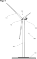
- FIG. 1 shows a schematic view of a wind turbine 100, which comprises a tower 102.
- the tower 102 is fixed to the ground by means of a foundation 104.
- a nacelle 106 is rotatably mounted at one end of the tower 102 opposite to the ground.
- the nacelle 106 for example, comprises a generator which is coupled to a rotor 108 via a rotor shaft (not shown).
- the rotor 108 comprises one or more (wind turbine) rotor blades 110, which are arranged on a rotor hub 112.
- the rotor 108 is set in rotation by an air flow, for example wind. This rotational movement is transmitted to the generator via the rotor shaft and, if necessary, a gearbox.
- the generator converts the kinetic energy of the rotor 108 into electrical energy.
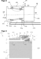
- Fig. 2 shows a simplified representation of an exemplary embodiment of a bearing arrangement 114 within wind turbine 100.
- the bearing arrangement 114 extends in the longitudinal axis 116 along an axis of rotation R from a front rotor side 118 to a rear side 120 (gearbox/generator side).
- the bearing arrangement 114 generally has a rotor shaft 124 as a rotor or rotating component, the rotor shaft 124 being connected to the rotor hub 112 (not illustrated) at the front rotor side 118 of the bearing arrangement 114.
- the bearing arrangement 114 has a bearing housing 126 as a stationary component, the bearing housing 126 being connected to a machine frame 122.
- the rotor shaft 124 and the bearing housing 126 are rotatably mounted on one another via two bearings, namely a gearbox-side bearing 128 (first bearing) and a rotor-side bearing 130 (second bearing).
- the two bearings are tapered roller bearings.
- the rotor shaft 124 rotates in operation about the axis of rotation R (rotational axis), whereas the bearing housing 126 is fixedly connected to the machine frame 122.
- the rotor shaft 124 is connected to a gearbox 132, in particular to a gearbox input shaft (not shown).
- the bearing housing 126 is connected to the gearbox 132, in particular to a housing of the gearbox 132, via a torque support arrangement 131.
- the presence of the torque support arrangement between the bearing housing 126 and the gearbox 132 renders access to the bearing arrangement from the gearbox side difficult or impossible.
- the gearbox 132 is connected to a generator (not shown) via an output shaft 134 of the gearbox 132.
- the bearing housing 126 is connected to a gearbox-generator assembly via a torque support arrangement.
- the gearbox-generator assembly corresponds in particular to a gearbox in which a generator is integrated.
- the wind turbine 100 does not comprise any gearbox (direct drive concept), such that the bearing housing 126 is connected to a generator via a torque support arrangement.
- a pretensioning member designed as a pretension ring 136 which acts on the respective first bearing 128 in the longitudinal axis 116 with a biasing force, so that the entire bearing arrangement 114 is biased and thus no clearance is provided in both the axial direction and in the radial direction with respect to the axis of rotation R.
- the pretensioning member may alternatively be designed e.g. as a shaft nut. The pretensioning force generated by the pretension ring 136 is transmitted via the respective first bearing 128 on the bearing housing 126, from there via the opposite second bearing 130 on the rotor shaft 124.
- the rotor shaft 124 typically comprises a shoulder 137 which serves as an axial abutment for the second bearing 130 on the front rotor side 118.
- the pretensioning force is then transmitted from the rotor shaft 124 back to the first bearing 128.
- a pretension circuit 138 is formed by these components, which is exemplified by the dotted lines in Fig. 2 .
- the bearing arrangement 114 including rotor shaft 124, bearing housing 126, bearings 128, 130 and pretension ring 136 is typically a preassembled unit, which is typically supplied in the assembled state to the site of the wind turbine and is finally mounted there with the rotor hub 112 and the machine frame 122. Alternately, at least part of the components of the bearing arrangement 114 may be separately supplied to the site of the wind turbine and assembled to the remaining components of the bearing arrangement 114 on site.
- the first roller bearing 128 and the second roller bearing 130 are tapered roller bearings and are arranged in the so-called "O"-arrangement.
- the first roller bearing 128 is arranged at the rear side 120 (generator side or gearbox side).
- the rotor shaft 124 is connected to a gearbox (not shown).
- the first roller bearing 128 comprises a first bearing inner ring 140, a first bearing outer ring 142 and rolling elements 143 arranged and supported between the first bearing inner ring 140 and the first bearing outer ring 142.
- the bearing arrangement 114 is operated such that a rotation of the rotor 108 drives the rotor shaft 124.
- the rotation of the rotor shaft 124 is transferred to the gearbox, via which a generator is driven to generate electrical energy.
- the bearing arrangement 114 of Fig. 3 is generally pretensioned as described above and in accordance with Fig. 2 , wherein instead of the pretension ring 136 another pretensioning device is used.
- the first roller bearing 128, the second roller bearing 130, the rotor shaft 124 and the bearing housing 126 are designed and arranged to form a pretension circuit 138.
- Each screw has an at least partially threaded screw shaft and is screwed into a corresponding opening 148 (here: through-hole) of the bearing housing 126 and is arranged such that it can be moved along a moving direction M wherein, in the present example, the moving direction M runs parallel to the rotational axis R, i.e. at an angle of 0° with respect to the rotational axis R.
- a force transfer element 150 is arranged between the adjustment devices 146 and the first bearing outer ring 142.
- the force transfer element 150 is a ring member extending circumferentially around the rotational axis R.
- the force transfer element 150 is washer-like and can also be called a pressure ring.
- the force transfer element 150 is axially moveable along the rotational axis R.
- the adjustment devices 146 are in direct contact with the force transfer element 150, wherein the latter is in direct contact with the first bearing outer ring 142.
- the screws 146 are actuated, i.e. torque is applied to the screws 146.
- the screws 146 are actuated (turned) such that they are moved (further) against the force transfer element 150 (towards the right in Fig. 3 ).
- a force F of each screw 146 is increased and this force F is transferred to the force transfer element 150.
- the force transfer element 150 is configured to distribute the load onto the first bearing outer ring 142, such that a resulting force FR acts on the first bearing outer ring 142. This causes axial movement/displacement of the first bearing outer ring 142 and thus impacts the pretension circuit 138. The pretension of the bearing arrangement 114 is thus adjusted.
- each screw 146 can be actuated such that it is moved away from the first bearing outer ring 142 and the force transfer element 150, meaning that the pretension can be reduced.
- the screws 146 are arranged between the first roller bearing 128 and the second roller bearing.
- the screws 146 are easily accessible from outside 152 of the bearing arrangement 114.
- the bearing housing 126 comprises a step 154 so that the screws 146 can be accommodated.
- the bearing housing 126 and or arrangements of the screws 146 are applicable.
- fine threads are used to allow fine tuning of the pretension, i.e. only fractions of a mm.
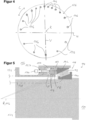
- bearing arrangement 114 is particularly noteworthy in bearing arrangement 114 is the fact that the pretensioning device 144 is configured such that the resulting force FR caused by the screws 146 is unevenly distributed over the circumference of the first roller bearing 128, as schematically indicated in figure 4.
- Figure 4 shows a cross-sectional schematic view of the bearing arrangement 114, wherein the cross section runs in normal direction to the rotational axis R.
- the bearing arrangement 114 as shown represents an intended installation state within the wind turbine 100. Further, a vertical plane V and a horizontal plane H are illustrated. As can be seen, in circumferential direction C several adjustment devices 146 are arranged entering through the bearing housing 126.
- the adjustment devices 146 have the same structure and are unevenly distributed around the circumference of the first roller bearing.
- the adjustment devices 146 are evenly distributed around the circumference of the first roller bearing 128, but are constructed or actuated differently to generate the uneven resulting force FR.
- the pretensioning device 144 i.e. the screws 146, can be force-controlled or displacement-controlled.
- the screws 146 could also act directly on the first bearing outer ring 142.
- the pretensioning device 144 e.g. the screws 146, could directly or indirectly provide a force F onto the first bearing inner ring 140.
- a pretension ring (see ring 136 in figure 2 as described above) can be used for pretension of the first roller bearing 128.
- the adjustment devices 146 can be designed and arranged differently. Further, the transfer of their forces onto the first roller bearing 128 can be carried out differently, e.g. via wedged shaped force transfer elements and so on. In this regard, we refer to the already named prior applications ( EP application numbers 23 17 8381 and 23 17 8382 ).
- FIGS 5 and 6 show a further embodiment of the invention, which differs regarding the pretensioning device 144 and the adjustment of the pretension.
- the above description of the features similarly applies, unless otherwise stated below.
- not all reference signs are necessarily reproduced in the figures and described again.
- the pretensioning device 144 comprises a hydraulic ring piston 156, which is arranged in the bearing housing 126 around the rotational axis R and is in direct contact with the first bearing outer ring 142.
- the hydraulic ring piston 156 has a different radial extension 158 (in other words thickness) along the circumferential direction C of the first roller bearing 128 with respect to the rotational axis R.
- a hydraulic force F can now be applied to the ring piston 156 by a hydraulic system connected to the housing 126 (not shown in figure 5 ).
- the hydraulic force F is generated by introducing a pressurized hydraulic fluid into a chamber 159 formed by the hollow space between the bearing housing 126 and the ring piston 156.
- O-ring seals 157 are provided between the ring piston 156 and the bearing housing 126 and between the screws 160 and the bearing housing 126 in order to prevent the hydraulic fluid from leaking out of the chamber 159.
- This hydraulic force F is transferred between the hydraulic ring piston 156 and the first bearing outer ring 142 and causes the unevenly distributed resulting force FR due to the inhomogeneous radial extension 158.
- One or more locking screws 160 are provided to hold the hydraulic ring piston in position and thus the pretension of the bearing arrangement 114 is maintained after having applied the hydraulic force F. This allows the hydraulic force to be released afterwards and the hydraulic system to be removed.
- Figure 7 shows a further embodiment of the invention, which is similar to the above-described embodiment with respect to figures 5 and 6 .
- the pretensioning device 144 comprises several hydraulic ring piston segments 162 which extend inside the bearing housing 162 around the rotational axis R to form a common segmented ring and are each in direct contact with the first bearing outer ring 142.
- the hydraulic ring piston segments are spaced apart from each other in the circumferential direction C and have a different arcuate extension around the rotational axis R.
- a hydraulic force F which is set or adjusted to act on the hydraulic ring piston segments 162, is transferred between the hydraulic ring piston segments 162 and the first bearing outer ring 142 to cause the unevenly distributed resulting force FR, in particular due to the differently designed segments 162.
- locking screws 160 are used to hold the position of the ring segments 162 and thus to maintain the pretension of the bearing arrangement 114.
- This embodiment enables higher forces at the same pressure and with the same radial space.
- An adaptation of necessary force can be achieved by providing different ring piston segments in the circumferential direction C (even ring piston segments can be used being only cylinders, e.g. at a bottom side of the first roller bearing 128).
- Figure 8 shows a further embodiment of the invention, which differs regarding the pretensioning device 144 and the adjustment of the pretension.
- the above description of the features similarly applies, unless otherwise stated below.
- not all reference signs are necessarily reproduced in the figures and described again.
- the bearing arrangement comprises a stationary shaft 124 as a stationary component and a rotating bearing housing 126 as a rotating component.
- the pretension device 144 is arranged at the stationary shaft 124. Therefore, similarly to the above embodiments, the pretension device 144 is arranged at the stationary component.
- the pretensioning device 144 comprises a clamping ring 164, which surrounds the stationary shaft 124 at an end face 166 thereof in a form-fit manner and which has a radially inwardly extending shoulder 168.
- the shoulder 168 abuts the end face 166 of the stationary shaft 124 axially with respect to the rotational axis R.
- the clamping ring 164 is screwed to the end face 166 of the stationary shaft 124 by means of several adjustment screws 146 in such a way that the clamping ring 164 is pressed against the first bearing inner ring 140 to cause the unevenly distributed resulting force FR.
Landscapes
- Engineering & Computer Science (AREA)
- General Engineering & Computer Science (AREA)
- Mechanical Engineering (AREA)
- Life Sciences & Earth Sciences (AREA)
- Sustainable Development (AREA)
- Sustainable Energy (AREA)
- Chemical & Material Sciences (AREA)
- Combustion & Propulsion (AREA)
- Support Of The Bearing (AREA)
Abstract
Description
- The invention relates to a bearing arrangement for a rotating component of a wind turbine.
- Wind turbines with wind turbine rotor blades (hereinafter also referred to as rotor blades) are well known in the prior art and are used to convert wind energy into electrical energy.
- In wind turbines, there are direct drive concepts in which the rotational motion of the rotor hub is transmitted directly and immediately to a rotating shaft of a generator. Alternatively, there are drive train concepts in which a gearbox is connected between the rotor hub and the generator, wherein the gearbox is connected to the rotor hub via a rotor shaft.
- A technical challenge for wind turbines of this type, which are designed for a power range of several megawatts of electrical power, for example, is the provision of a bearing arrangement that meets high technical requirements, such as high bending stiffness, a clearance-free bearing arrangement, low-wear kinematics and the simplest possible assembly combined with high cost-efficiency.
- It is known to use roller bearings, e.g. tapered roller bearings, to support rotating components of wind turbines, like the rotor shaft. Some roller bearings such as tapered roller bearings are designed to work in pairs. These tapered roller bearings are pretensioned, which means that even with no external load they have a minimum load to allow all rolling elements of the roller bearings to interact with the raceways. This is advantageous in terms of load distribution and contributes to an improved lifetime. This pretension should be kept within narrow limits so that, on the one hand, the positive effect of all rolling elements being in contact with the raceways is ensured and, on the other hand, the roller bearings are not overloaded.
- One task underlying the invention is to develop a concept for a bearing arrangement to support a rotating element of a wind turbine, which contributes to an efficient adjustment of the level of pretension.
- This object is solved by the independent claim. Advantageous embodiments are given in the sub-claims.
- A bearing arrangement is disclosed, in particular a rotor bearing arrangement, for a rotating component of a wind turbine, in particular for a rotor shaft. The bearing arrangement comprises a first roller bearing and a second roller bearing. The bearing arrangement comprises the rotating component having a rotational axis, wherein the rotating component is supported by the first roller bearing and the second roller bearing. A stationary component is provided, in particular a bearing housing, for supporting the first roller bearing and the second roller bearing. The first roller bearing, the second roller bearing, the rotating component and the stationary component are arranged to form a pretension circuit. The first roller bearing comprises a first bearing inner ring, a first bearing outer ring and rolling elements arranged between the first bearing inner ring and the first bearing outer ring. The bearing arrangement comprises a pretensioning device being configured such that, upon actuation, the pretensioning device causes a resulting force onto the first bearing inner ring or the first bearing outer ring to adjust the pretension of the bearing arrangement, wherein the resulting force is unevenly distributed over a circumference of the first roller bearing with respect to the rotational axis.
- As indicated above, a predetermined pretension of the bearing arrangement is necessary and is initially set, e.g. during assembly or installation in the field. For example, a mean value of pretension is used as a reference value. For different reasons, an adjustment of the pretension can be necessary, for example due to wear. Therefore, it is necessary and advantageous to control and adjust the level of pretension, not only during the production/mounting, but even during operation/maintenance.
- The pretension is applied by the pretensioning device by moving/deforming parts (e.g. bearing inner or outer ring). Thereby, an associated friction has to be overcome. This friction is mainly influenced by radial forces which are part of the load acting on the bearing arrangement and in particular on the first roller bearing. These radial forces are mainly associated with a static load which is caused by the rotor weight. Preferably, the pretensioning device acts on the stationary ring of the first roller bearing, either the outer ring or the inner ring.
- The invention takes into account that the load acting on the bearing arrangement, in particular on the first roller bearing, is not homogenous around the circumference, but is uneven mainly due to the rotor weight causing a static load acting mainly in a radial direction, such that the friction to be overcome is uneven around the circumference. In order to compensate for the uneven load, the resulting force of the pretensioning device is unevenly distributed over the circumference. Thus, an optimized pretension distribution around the circumference of the first roller bearing and thus the bearing arrangement can be achieved. This solution serves to achieve all the benefits of the pretension and in particular contributes to reducing wear and to optimizing the lifetime of the bearing arrangement. This solution allows a resulting force distribution to be adapted according to what is needed to overcome the friction. Thus, the distribution of pretensioning force can be optimized.
- The first roller bearing and the second roller bearing can be distant from one another in the axial direction. The first roller bearing is preferably the rear bearing, meaning that the first roller bearing is arranged at a gearbox side, facing the gearbox of the wind turbine. The second bearing comprises a second bearing inner ring, a second bearing outer ring, and rolling elements therebetween. The second roller bearing is preferably facing the rotor side.
- The pretension circuit means that the two roller bearings, e.g. tapered roller bearings, the rotating component and the bearing housing are formed and configured such that these elements can be/are pretensioned against each other.
- The stationary component can be named "stator". Preferably, the stationary component is the bearing housing. For example, the bearing housing is the outer housing, being arranged facing the outside of the bearing arrangement. In other words, the bearing housing is arranged away from the rotational axis.
- According to an embodiment, a homogeneous pretension can be adjusted over the circumference of the first rolling bearing by the unevenly distributed resulting force. This contributes to the above functions and advantages and offers a simple way of implementing the invention. For example, predicting or calculating the resulting force leading to the homogeneous pretension is easy compared to an inhomogeneous pretension. Further, setting a homogeneous pretension is comparably easy to set or adjust via the pretensioning device.
- According to an embodiment, an inhomogeneous pretension can be adjusted over the circumference of the first rolling bearing by the unevenly distributed resulting force. Thus, by providing an uneven resulting force an unevenly distributed pretension is provided, which could be beneficial in certain circumstances. In particular, such an arrangement could provide an optimized pretension distribution for facing situations in which the load acting on the bearing arrangement is such that a specific bearing area may experience a loss of pretension, thus leading to a risk of slippage in said specific bearing area. For example, the inhomogeneous pretension can be adjusted over the circumference of the first rolling bearing by the unevenly distributed resulting force such that the pretension force is higher in the lower bearing area than in the higher bearing area. Thus, the risk of slippage in the lower bearing area can be reduced.
- According to an embodiment, upon actuation of the pretensioning device, the first bearing inner ring or the first bearing outer ring is axially moved along the rotational axis with respect to the stationary component, and/or radially deformed with respect to the rotational axis. For example, the first bearing inner ring or first bearing outer ring is axially moveable along the rotational axis, which means along a direction parallel to the rotational axis. Alternatively or additionally, the first bearing outer ring is deformed in a radial direction with respect to the rotational axis. In any case, the movement or deformation is caused by actuation of the pretensioning device, wherein a mechanical force is transferred onto the first bearing outer ring or first bearing inner ring, either directly or indirectly.
- According to an embodiment, the pretensioning device is either force-controlled or displacement-controlled for applying the uneven force. This means that the pretensioning device is either set to exert a non-uniform force around the circumference of the first roller bearing and/or is set to provide a non-uniform displacement of the first bearing inner/outer ring so that the non-uniform load on the bearing is compensated for to realize said pretension target.
- According to an embodiment, the pretensioning device is located between the first roller bearing and the second roller bearing with respect to the rotational axis. Thus, the pretensioning device can be easily accessed from outside the bearing housing and it is not necessary to access the pretensioning device from the gearbox side.
- According to an embodiment, the pretensioning device comprises several single adjustment devices, which are configured to be actuated to commonly cause the resulting force. For example, the adjustment devices are screws, hydraulic cylinders, piezo elements, pneumatic elements or thermocouples. These adjustment devices are arranged along the circumference of the first bearing outer ring or first bearing inner ring, more specifically the outer ring or the inner ring at the gearbox side.
- According to an embodiment, the adjustment devices have the same structure but are unevenly distributed around the circumference of the first roller bearing.
- According to an embodiment, the adjustment devices are evenly distributed around the circumference of the first roller bearing but are constructed or actuated differently to generate the uneven resulting force.
- According to an embodiment, each adjustment device extends through an opening of the stationary component and is accessible from outside the stationary component. The mentioned opening goes through an entire wall (portion) of the bearing housing, e.g. in contrast to a blind hole. The opening is designed such that actuation of the adjustment device is possible. In other words, the opening needs to be large enough to allow actuation, i.e. movement, of the actuation device. For example, the opening is slit-shaped and runs over at least a portion of the bearing housing circumferentially around the rotational axis.
- According to an embodiment, each adjustment device is arranged inside the stationary component.
- According to an embodiment, each adjustment device directly acts on the first bearing inner ring or the first bearing outer ring. Thus, no further component(s) is/are arranged between an adjustment device and the respective bearing ring.
- According to an embodiment, a ring-shaped force transfer element is provided between the adjustment devices and the first bearing inner ring or the first bearing outer ring, such that a force, which is set or adjusted upon actuation of each adjustment device, can be transferred between the adjustment devices and the first bearing inner ring or the first bearing outer ring. For example, the force transfer element is formed homogenously around the circumference of the first roller bearing.
- According to an embodiment, the pretensioning device comprises a hydraulic ring piston, which is arranged in the stationary component around the rotational axis and is in direct contact with the first bearing outer ring, wherein the hydraulic ring piston has a different radial extension along the circumference of the first roller bearing with respect to the rotational axis such that a hydraulic force, which is set or adjusted to act on the hydraulic ring piston, is transferred between the hydraulic ring piston and the first bearing outer ring to cause the unevenly distributed resulting force. Thus, for example, the pretension of the bearing arrangement can be adjusted very precisely.
- According to an embodiment, the pretensioning device comprises several hydraulic ring piston segments, which extend inside the stationary component around the rotational axis to form a common segmented ring and are each in direct contact with the first bearing outer ring, wherein the hydraulic ring piston segments are spaced apart from each other and have a different arcuate extension around the rotational axis, such that a hydraulic force, which is set or adjusted to act on the hydraulic ring piston segments, is transferred between the hydraulic ring piston segments and the first bearing outer ring to cause the unevenly distributed resulting force. The ring piston segments are differently formed with respect to an extension along the circumference of the first roller bearing.
- According to an embodiment, the pretensioning device comprises a clamping ring, which surrounds the rotating element at an end face thereof in a form-fit manner and which has a radially inwardly extending shoulder which abuts the end face of the rotating element axially with respect to the rotational axis, wherein the clamping ring is screwed to the end face of the rotating element by means of several adjustment screws in such a way that the clamping ring is pressed against the first bearing inner ring to cause the unevenly distributed resulting force.
- Regarding the above embodiments, in particular with regard to the different embodiments of the adjustment devices, we refer to two European patent applications (
EP application numbers 23 17 8381 23 17 8382 - Further advantages, features and further developments are set out by the following exemplary embodiments which are explained in conjunction with the figures. The same or similar elements or elements acting in the same way are provided with the same reference numerals in the figures, wherein:
-
Fig. 1 shows a schematic illustration of a wind turbine, -
Fig. 2 shows a simplified, partial illustration of a bearing arrangement in a final mounted position with a gearbox connected between the bearing arrangement and a generator according to the prior art, and -
Fig. 3 to 8 show schematic sectional views of bearing arrangements according to embodiments of the invention. -
Figure 1 shows a schematic view of awind turbine 100, which comprises atower 102. Thetower 102 is fixed to the ground by means of afoundation 104. Anacelle 106 is rotatably mounted at one end of thetower 102 opposite to the ground. Thenacelle 106, for example, comprises a generator which is coupled to arotor 108 via a rotor shaft (not shown). Therotor 108 comprises one or more (wind turbine)rotor blades 110, which are arranged on arotor hub 112. - During operation, the
rotor 108 is set in rotation by an air flow, for example wind. This rotational movement is transmitted to the generator via the rotor shaft and, if necessary, a gearbox. The generator converts the kinetic energy of therotor 108 into electrical energy. -
Fig. 2 shows a simplified representation of an exemplary embodiment of abearing arrangement 114 withinwind turbine 100. Thebearing arrangement 114 extends in thelongitudinal axis 116 along an axis of rotation R from afront rotor side 118 to a rear side 120 (gearbox/generator side). Thebearing arrangement 114 generally has arotor shaft 124 as a rotor or rotating component, therotor shaft 124 being connected to the rotor hub 112 (not illustrated) at thefront rotor side 118 of thebearing arrangement 114. Furthermore, thebearing arrangement 114 has a bearinghousing 126 as a stationary component, the bearinghousing 126 being connected to amachine frame 122. Therotor shaft 124 and the bearinghousing 126 are rotatably mounted on one another via two bearings, namely a gearbox-side bearing 128 (first bearing) and a rotor-side bearing 130 (second bearing). Typically, the two bearings are tapered roller bearings. - The
rotor shaft 124 rotates in operation about the axis of rotation R (rotational axis), whereas the bearinghousing 126 is fixedly connected to themachine frame 122. In the shown embodiment according toFig. 2 therotor shaft 124 is connected to agearbox 132, in particular to a gearbox input shaft (not shown). The bearinghousing 126 is connected to thegearbox 132, in particular to a housing of thegearbox 132, via a torque support arrangement 131. The presence of the torque support arrangement between the bearinghousing 126 and thegearbox 132 renders access to the bearing arrangement from the gearbox side difficult or impossible. Thegearbox 132 is connected to a generator (not shown) via anoutput shaft 134 of thegearbox 132. - In an alternative non-illustrated embodiment, the bearing
housing 126 is connected to a gearbox-generator assembly via a torque support arrangement. The gearbox-generator assembly corresponds in particular to a gearbox in which a generator is integrated. In a further non-illustrated embodiment, thewind turbine 100 does not comprise any gearbox (direct drive concept), such that the bearinghousing 126 is connected to a generator via a torque support arrangement. - Referring again to the embodiment of
Fig. 2 , at thefirst bearing 128 at the tapered end of therotor shaft 124, a pretensioning member designed as apretension ring 136 is arranged which acts on the respectivefirst bearing 128 in thelongitudinal axis 116 with a biasing force, so that theentire bearing arrangement 114 is biased and thus no clearance is provided in both the axial direction and in the radial direction with respect to the axis of rotation R. The pretensioning member may alternatively be designed e.g. as a shaft nut. The pretensioning force generated by thepretension ring 136 is transmitted via the respectivefirst bearing 128 on the bearinghousing 126, from there via the oppositesecond bearing 130 on therotor shaft 124. Therotor shaft 124 typically comprises ashoulder 137 which serves as an axial abutment for thesecond bearing 130 on thefront rotor side 118. The pretensioning force is then transmitted from therotor shaft 124 back to thefirst bearing 128. Thus, apretension circuit 138 is formed by these components, which is exemplified by the dotted lines inFig. 2 . - The
bearing arrangement 114 includingrotor shaft 124, bearinghousing 126,bearings pretension ring 136 is typically a preassembled unit, which is typically supplied in the assembled state to the site of the wind turbine and is finally mounted there with therotor hub 112 and themachine frame 122. Alternately, at least part of the components of thebearing arrangement 114 may be separately supplied to the site of the wind turbine and assembled to the remaining components of thebearing arrangement 114 on site. - In the following, embodiments of the invention are described which focus on an improved pretensioning mechanism.
-
Fig. 3 shows aschematic bearing arrangement 114 according to an embodiment of the invention. Thebearing arrangement 114 is generally of the type as described with reference toFig. 2 above. Thebearing arrangement 114 has a bearinghousing 126, a rotor shaft 124 (corresponding to a rotating component), afirst roller bearing 128 and a second roller bearing 130 (not shown for the sake of overview). Thebearing arrangement 114 has alongitudinal axis 116 and therotor shaft 124 rotates around a rotational axis R. The bearinghousing 126 supports the first and thesecond roller bearings second roller bearings rotor shaft 124. Thefirst roller bearing 128 and thesecond roller bearing 130 are tapered roller bearings and are arranged in the so-called "O"-arrangement. Thefirst roller bearing 128 is arranged at the rear side 120 (generator side or gearbox side). At therear side 120, therotor shaft 124 is connected to a gearbox (not shown). Thefirst roller bearing 128 comprises a first bearinginner ring 140, a first bearingouter ring 142 and rollingelements 143 arranged and supported between the first bearinginner ring 140 and the first bearingouter ring 142. - In an installed state within the
wind turbine 100, thebearing arrangement 114 is operated such that a rotation of therotor 108 drives therotor shaft 124. The rotation of therotor shaft 124 is transferred to the gearbox, via which a generator is driven to generate electrical energy. - The
bearing arrangement 114 ofFig. 3 is generally pretensioned as described above and in accordance withFig. 2 , wherein instead of thepretension ring 136 another pretensioning device is used. In this regard, thefirst roller bearing 128, thesecond roller bearing 130, therotor shaft 124 and the bearinghousing 126 are designed and arranged to form apretension circuit 138. - A
pretensioning device 144 is provided to set/adjust the pretension of thebearing arrangement 114, i.e. to adjust the pretension of the formedpretension circuit 138. Thepretensioning device 144 comprises severalsingle adjustment devices 146 arranged circumferentially around thefirst roller bearing 140 with respect to the rotational axis R (only oneadjustment device 146 shown). The first bearingouter ring 142 can be axially moved via theadjustment devices 146, i.e. in a direction parallel to the rotational axis R. In the shown embodiment, theadjustment devices 146 are screws (also called "pressure screws"). Each screw has an at least partially threaded screw shaft and is screwed into a corresponding opening 148 (here: through-hole) of the bearinghousing 126 and is arranged such that it can be moved along a moving direction M wherein, in the present example, the moving direction M runs parallel to the rotational axis R, i.e. at an angle of 0° with respect to the rotational axis R. - A
force transfer element 150 is arranged between theadjustment devices 146 and the first bearingouter ring 142. Theforce transfer element 150 is a ring member extending circumferentially around the rotational axis R. For example, theforce transfer element 150 is washer-like and can also be called a pressure ring. Theforce transfer element 150 is axially moveable along the rotational axis R. - In the pretensioned state as shown, the
adjustment devices 146 are in direct contact with theforce transfer element 150, wherein the latter is in direct contact with the first bearingouter ring 142. - To adjust the pretension of the
bearing arrangement 114, thescrews 146 are actuated, i.e. torque is applied to thescrews 146. To increase the pretension, thescrews 146 are actuated (turned) such that they are moved (further) against the force transfer element 150 (towards the right inFig. 3 ). Thus, a force F of eachscrew 146 is increased and this force F is transferred to theforce transfer element 150. Theforce transfer element 150 is configured to distribute the load onto the first bearingouter ring 142, such that a resulting force FR acts on the first bearingouter ring 142. This causes axial movement/displacement of the first bearingouter ring 142 and thus impacts thepretension circuit 138. The pretension of thebearing arrangement 114 is thus adjusted. - Similarly, each
screw 146 can be actuated such that it is moved away from the first bearingouter ring 142 and theforce transfer element 150, meaning that the pretension can be reduced. - As can be seen from
Fig. 3 , thescrews 146 are arranged between thefirst roller bearing 128 and the second roller bearing. Thus, thescrews 146 are easily accessible from outside 152 of thebearing arrangement 114. For adjustment of the pretension, it is thus not necessary to gain access from the rear (gearbox)side 120, which is particularly problematic after thebearing arrangement 114 has been installed in thewind turbine 100 and/or during operation of thewind turbine 100. - In the shown embodiment, the bearing
housing 126 comprises astep 154 so that thescrews 146 can be accommodated. Of course, other designs of the bearinghousing 126 and or arrangements of thescrews 146 are applicable. - With the
screws 146, a very precise adjustment of the pretension is possible. Preferably, fine threads are used to allow fine tuning of the pretension, i.e. only fractions of a mm. - Particularly noteworthy in bearing
arrangement 114 is the fact that thepretensioning device 144 is configured such that the resulting force FR caused by thescrews 146 is unevenly distributed over the circumference of thefirst roller bearing 128, as schematically indicated infigure 4. Figure 4 shows a cross-sectional schematic view of thebearing arrangement 114, wherein the cross section runs in normal direction to the rotational axis R. Thebearing arrangement 114 as shown represents an intended installation state within thewind turbine 100. Further, a vertical plane V and a horizontal plane H are illustrated. As can be seen, in circumferential direction Cseveral adjustment devices 146 are arranged entering through the bearinghousing 126. In the intended installed state of thebearing arrangement 114,more adjustment devices 144 are arranged above the horizontal plane H, in which the rotational axis R runs, than below the horizontal plane H. This configuration allows the resulting force FR to be unevenly distributed in order to compensate for the inhomogeneous loads acting on thebearing arrangement 114, as described in the introductory portion. If eachscrew 146 is essentially equally actuated, e.g. turned, the resulting force FR is unevenly distributed since thescrews 146 are unevenly distributed around the circumference. By this measure, the pretension of thebearing arrangement 114 can be evenly distributed over the whole first bearingouter ring 142. In other words, the pretension is homogeneously set/adjusted over the circumference of thefirst roller bearing 128. - Alternatively, with the described arrangement it is possible that a predetermined uneven pretension is achieved with an unevenly distributed resulting force FR.
- In the described embodiment with regard to
figures 3 and4 , theadjustment devices 146 have the same structure and are unevenly distributed around the circumference of the first roller bearing. In an alternative example, in order to achieve the uneven distribution of the resulting force FR, theadjustment devices 146 are evenly distributed around the circumference of thefirst roller bearing 128, but are constructed or actuated differently to generate the uneven resulting force FR. - The
pretensioning device 144, i.e. thescrews 146, can be force-controlled or displacement-controlled. - Instead of acting on the force-
transfer element 150, thescrews 146 could also act directly on the first bearingouter ring 142. - Alternatively, the
pretensioning device 144, e.g. thescrews 146, could directly or indirectly provide a force F onto the first bearinginner ring 140. For example, a pretension ring (seering 136 infigure 2 as described above) can be used for pretension of thefirst roller bearing 128. - The
adjustment devices 146 can be designed and arranged differently. Further, the transfer of their forces onto thefirst roller bearing 128 can be carried out differently, e.g. via wedged shaped force transfer elements and so on. In this regard, we refer to the already named prior applications (EP application numbers 23 17 8381 23 17 8382 -
Figures 5 and6 show a further embodiment of the invention, which differs regarding thepretensioning device 144 and the adjustment of the pretension. Thus, the above description of the features similarly applies, unless otherwise stated below. For the sake of clarity, however, not all reference signs are necessarily reproduced in the figures and described again. - As a main difference, the
pretensioning device 144 comprises ahydraulic ring piston 156, which is arranged in the bearinghousing 126 around the rotational axis R and is in direct contact with the first bearingouter ring 142. Thehydraulic ring piston 156 has a different radial extension 158 (in other words thickness) along the circumferential direction C of thefirst roller bearing 128 with respect to the rotational axis R. A hydraulic force F can now be applied to thering piston 156 by a hydraulic system connected to the housing 126 (not shown infigure 5 ). The hydraulic force F is generated by introducing a pressurized hydraulic fluid into achamber 159 formed by the hollow space between the bearinghousing 126 and thering piston 156. O-ring seals 157 are provided between thering piston 156 and the bearinghousing 126 and between thescrews 160 and the bearinghousing 126 in order to prevent the hydraulic fluid from leaking out of thechamber 159. This hydraulic force F is transferred between thehydraulic ring piston 156 and the first bearingouter ring 142 and causes the unevenly distributed resulting force FR due to the inhomogeneousradial extension 158. One or more locking screws 160 are provided to hold the hydraulic ring piston in position and thus the pretension of thebearing arrangement 114 is maintained after having applied the hydraulic force F. This allows the hydraulic force to be released afterwards and the hydraulic system to be removed. -
Figure 7 shows a further embodiment of the invention, which is similar to the above-described embodiment with respect tofigures 5 and6 . Thus, the above description of the features and the shown embodiment offigure 5 similarly apply, unless otherwise stated below. As a difference to the above, thepretensioning device 144 comprises several hydraulicring piston segments 162 which extend inside the bearinghousing 162 around the rotational axis R to form a common segmented ring and are each in direct contact with the first bearingouter ring 142. The hydraulic ring piston segments are spaced apart from each other in the circumferential direction C and have a different arcuate extension around the rotational axis R. A hydraulic force F, which is set or adjusted to act on the hydraulicring piston segments 162, is transferred between the hydraulicring piston segments 162 and the first bearingouter ring 142 to cause the unevenly distributed resulting force FR, in particular due to the differently designedsegments 162. Again, lockingscrews 160 are used to hold the position of thering segments 162 and thus to maintain the pretension of thebearing arrangement 114. - This embodiment enables higher forces at the same pressure and with the same radial space. An adaptation of necessary force can be achieved by providing different ring piston segments in the circumferential direction C (even ring piston segments can be used being only cylinders, e.g. at a bottom side of the first roller bearing 128).
-
Figure 8 shows a further embodiment of the invention, which differs regarding thepretensioning device 144 and the adjustment of the pretension. Thus, the above description of the features similarly applies, unless otherwise stated below. For the sake of clarity, however, not all reference signs are necessarily reproduced in the figures and described again. - In the embodiment of
figure 8 the bearing arrangement comprises astationary shaft 124 as a stationary component and a rotating bearinghousing 126 as a rotating component. Thepretension device 144 is arranged at thestationary shaft 124. Therefore, similarly to the above embodiments, thepretension device 144 is arranged at the stationary component. Thepretensioning device 144 comprises aclamping ring 164, which surrounds thestationary shaft 124 at an end face 166 thereof in a form-fit manner and which has a radially inwardly extendingshoulder 168. Theshoulder 168 abuts the end face 166 of thestationary shaft 124 axially with respect to the rotational axis R. Theclamping ring 164 is screwed to the end face 166 of thestationary shaft 124 by means ofseveral adjustment screws 146 in such a way that theclamping ring 164 is pressed against the first bearinginner ring 140 to cause the unevenly distributed resulting force FR. -
- 100
- wind turbine
- 102
- tower
- 104
- foundation
- 106
- nacelle
- 108
- rotor
- 110
- rotor blade
- 112
- rotor hub
- 114
- bearing arrangement
- 116
- longitudinal direction
- 118
- front rotor side
- 120
- rear side
- 122
- machine frame
- 124
- rotor shaft, stationary shaft
- 126
- bearing housing, rotating bearing housing
- 128
- first bearing
- 130
- second bearing
- 131
- torque support arrangement
- 132
- gearbox
- 134
- output shaft
- 136
- pretension ring
- 137
- shoulder
- 138
- pretension circuit
- 140
- first bearing inner ring
- 142
- first bearing outer ring
- 143
- rolling element
- 144
- pretensioning device
- 146
- adjustment device
- 148
- opening
- 150
- force transfer element
- 152
- outside
- 154
- step
- 156
- hydraulic ring piston
- 157
- O-ring seal
- 158
- radial extension
- 159
- chamber
- 160
- locking screws
- 162
- hydraulic ring piston segments
- 164
- clamping ring
- 166
- end face
- 168
- shoulder
- C
- circumferential direction
- F
- force
- H
- horizontal plane
- FR
- resulting force
- M
- moving direction
- R
- rotational axis
- V
- vertical plane
Claims (15)
- Bearing arrangement (114), in particular a rotor bearing arrangement (114), for a rotating component of a wind turbine (100), comprising- a first roller bearing (128) and a second roller bearing (130),- the rotating component having a rotational axis (R), the rotating component being supported by the first roller bearing (128) and the second roller bearing (130), and- a stationary component, in particular a bearing housing (126), supporting the first roller bearing (128) and the second roller bearing (130), whereinthe first roller bearing (128), the second roller bearing (130), the rotating component and the stationary component are arranged to form a pretension circuit (138), andthe first roller bearing (128) comprises a first bearing inner ring (140), a first bearing outer ring (142) and rolling elements (143) arranged between the first bearing inner ring (140) and the first bearing outer ring (142),- a pretensioning device (144) being configured such that, upon actuation, the pretensioning device (144) causes a resulting force (FR) onto the first bearing inner ring (140) or the first bearing outer ring (142) to adjust the pretension of the bearing arrangement (114), wherein the resulting force (FR) is unevenly distributed over a circumference of the first roller bearing (128) with respect to the rotational axis (R) .
- Bearing arrangement (114) according to claim 1, wherein a homogeneous pretension can be adjusted over the circumference of the first rolling bearing (128) by the unevenly distributed resulting force (FR).
- Bearing arrangement (114) according to claim 1, wherein an inhomogeneous pretension can be adjusted over the circumference of the first rolling bearing (128) by the unevenly distributed resulting force (FR).
- Bearing arrangement (114) according to any one of claims 1 to 3, wherein upon actuation of the pretensioning device (144) the first bearing inner ring (140) or the first bearing outer ring (142) is axially moved along the rotational axis (R) with respect to the stationary component, and/or radially deformed with respect to the rotational axis (R).
- Bearing arrangement (114) according to any one of the preceding claims, wherein the pretensioning device (144) is either force-controlled or displacement-controlled for applying the uneven force.
- Bearing arrangement (114) according to any one of the preceding claims, wherein the pretensioning device (144) is located between the first roller bearing (128) and the second roller bearing (130) with respect to the rotational axis (R).
- Bearing arrangement (114) according to any one of the preceding claims, wherein the pretensioning device (144) comprises several single adjustment devices (146), which are configured to be actuated to commonly cause the resulting force (FR).
- Bearing arrangement (114) according to claim 7, wherein the adjustment devices (146) have the same structure, but are unevenly distributed around the circumference of the first roller bearing (128).
- Bearing arrangement (114) according to claim 7, wherein the adjustment devices (146) are evenly distributed around the circumference of the first roller bearing (128), but are constructed or actuated differently to generate the uneven resulting force (FR).
- Bearing arrangement (114) according to any one of claims 7 to 9, wherein each adjustment device (146) extends through an opening (152) of the stationary component and is accessible from outside (158) the stationary component.
- Bearing arrangement (114) according to any one of claims 7 to 9, wherein each adjustment device (146) is arranged inside the stationary component.
- Bearing arrangement (114) according to any one of claims 7 to 11, wherein each adjustment device (146) directly acts on the first bearing inner ring (140) or the first bearing outer ring (142).
- Bearing arrangement (114) according to any one of claims 7 to 11, wherein a ring-shaped force transfer element (156) is provided between the adjustment devices (146) and the first bearing inner ring (140) or the first bearing outer ring (142), such that a force (F), which is set or adjusted upon actuation of each adjustment device (146), can be transferred between the adjustment devices (146) and the first bearing inner ring (140) or the first bearing outer ring (142).
- Bearing arrangement (114) according to any one of claims 1 to 6, wherein the pretensioning device (144) comprises a hydraulic ring piston (156), which is arranged in the stationary component around the rotational axis (R) and is in direct contact with the first bearing outer ring (142), wherein the hydraulic ring piston (156) has a different radial extension along the circumference of the first roller bearing (128) with respect to the rotational axis (R), such that a hydraulic force (F), which is set or adjusted to act on the hydraulic ring piston (156), is transferred between the hydraulic ring piston (156) and the first bearing outer ring (142) to cause the unevenly distributed resulting force (FR) .
- Bearing arrangement (114) according to any one of claims 1 to 6, wherein the pretensioning device (144) comprises several hydraulic ring piston segments (162) which extend inside the stationary component around the rotational axis (R) to form a common segmented ring and are each in direct contact with the first bearing outer ring (142), wherein the hydraulic ring piston segments (162) are spaced apart from each other and have a different arcuate extension around the rotational axis (R), such that a hydraulic force (F), which is set or adjusted to act on the hydraulic ring piston segments (162), is transferred between the hydraulic ring piston segments (162) and the first bearing outer ring (142) to cause the unevenly distributed resulting force (FR).
Priority Applications (2)
| Application Number | Priority Date | Filing Date | Title |
|---|---|---|---|
| EP23217477.1A EP4575251A1 (en) | 2023-12-18 | 2023-12-18 | Bearing arrangement for a rotating component of a wind turbine |
| US18/937,945 US20250198454A1 (en) | 2023-12-18 | 2024-11-05 | Bearing arrangement for a rotating component of a wind turbine |
Applications Claiming Priority (1)
| Application Number | Priority Date | Filing Date | Title |
|---|---|---|---|
| EP23217477.1A EP4575251A1 (en) | 2023-12-18 | 2023-12-18 | Bearing arrangement for a rotating component of a wind turbine |
Publications (1)
| Publication Number | Publication Date |
|---|---|
| EP4575251A1 true EP4575251A1 (en) | 2025-06-25 |
Family
ID=89223618
Family Applications (1)
| Application Number | Title | Priority Date | Filing Date |
|---|---|---|---|
| EP23217477.1A Pending EP4575251A1 (en) | 2023-12-18 | 2023-12-18 | Bearing arrangement for a rotating component of a wind turbine |
Country Status (2)
| Country | Link |
|---|---|
| US (1) | US20250198454A1 (en) |
| EP (1) | EP4575251A1 (en) |
Citations (3)
| Publication number | Priority date | Publication date | Assignee | Title |
|---|---|---|---|---|
| JP2006177268A (en) * | 2004-12-24 | 2006-07-06 | Nsk Ltd | Rotation support device for wind power generator |
| US20150030277A1 (en) * | 2012-04-13 | 2015-01-29 | Eolotec Gmbh | Bearing arrangement of a wind turbine and method for adjusting the preload of a bearing arrangement |
| US20200362917A1 (en) * | 2018-02-07 | 2020-11-19 | The Timken Company | Roller seating device for tapered roller bearings |
Family Cites Families (2)
| Publication number | Priority date | Publication date | Assignee | Title |
|---|---|---|---|---|
| SE506134C2 (en) * | 1995-03-31 | 1997-11-17 | Sprout Bauer Inc Andritz | Biasing device for a radial bearing unit |
| EP2801729B1 (en) * | 2013-05-06 | 2018-01-03 | Eolotec GmbH | Main bearing, in particular main bearing of a wind turbine and method for determining a bearing clearance of a roller bearing and wind turbine |
-
2023
- 2023-12-18 EP EP23217477.1A patent/EP4575251A1/en active Pending
-
2024
- 2024-11-05 US US18/937,945 patent/US20250198454A1/en active Pending
Patent Citations (3)
| Publication number | Priority date | Publication date | Assignee | Title |
|---|---|---|---|---|
| JP2006177268A (en) * | 2004-12-24 | 2006-07-06 | Nsk Ltd | Rotation support device for wind power generator |
| US20150030277A1 (en) * | 2012-04-13 | 2015-01-29 | Eolotec Gmbh | Bearing arrangement of a wind turbine and method for adjusting the preload of a bearing arrangement |
| US20200362917A1 (en) * | 2018-02-07 | 2020-11-19 | The Timken Company | Roller seating device for tapered roller bearings |
Also Published As
| Publication number | Publication date |
|---|---|
| US20250198454A1 (en) | 2025-06-19 |
Similar Documents
| Publication | Publication Date | Title |
|---|---|---|
| US9284949B2 (en) | Bearing arrangement of a wind turbine and method for adjusting the preload of a bearing arrangement | |
| US8858382B2 (en) | Pin retainer | |
| DK2847497T3 (en) | PLANET GEARTRINE WITH SLIDE BEARINGS AS PLANET BEARINGS AND USE THEREOF | |
| US8900092B2 (en) | Planetary gear mechanism | |
| EP2072858B1 (en) | A planetary type gear unit comprising a planet carrier with a planet bogie plate | |
| US9011010B2 (en) | Hybrid wind turbine blade bearing | |
| WO2012146751A2 (en) | Pitch drive system and method | |
| NL2003925C2 (en) | Main bearing for a wind turbine. | |
| US8911211B2 (en) | Wind turbine | |
| US11933362B2 (en) | Method and device for replacing a used bearing, in particular for replacing a main bearing of a wind turbine, and bearing arrangement in particular of a wind turbine | |
| KR20160134840A (en) | Hybrid shaft bearing with a hydrodynamic bearing and a rolling bearing, wind generator comprising a hybrid shaft bearing, use of the hybrid shaft bearing and method of operating the hybrid shaft bearing | |
| US20130292948A1 (en) | Monobearing eolic turbine with radial flow electric generator and external stator | |
| US20180245571A1 (en) | Gearbox for a wind turbine | |
| KR20190042069A (en) | Lever type Brake device | |
| US20240410419A1 (en) | Bearing arrangement for a rotating component of a wind turbine | |
| US20200347829A1 (en) | Torque support arrangement for a wind power gearbox | |
| EP1995454B1 (en) | Device for the adjustment of the pitch of a rotor blade of a wind turbine | |
| US20250198454A1 (en) | Bearing arrangement for a rotating component of a wind turbine | |
| EP4031763B1 (en) | Wind turbine yaw brake with anti-rotation bushing | |
| US12535059B2 (en) | Support apparatus for shaft system, and wind turbine | |
| US20240410420A1 (en) | Bearing arrangement for a rotating component of a wind turbine | |
| US20130259683A1 (en) | Ram air turbine biasing assembly | |
| CN121760888A (en) | Transmission device, transmission system, wind generating set and maintenance method | |
| US20260117747A1 (en) | Transmission mounting for a wind turbine | |
| EP4108944B1 (en) | Yaw bearing assembly |
Legal Events
| Date | Code | Title | Description |
|---|---|---|---|
| PUAI | Public reference made under article 153(3) epc to a published international application that has entered the european phase |
Free format text: ORIGINAL CODE: 0009012 |
|
| STAA | Information on the status of an ep patent application or granted ep patent |
Free format text: STATUS: THE APPLICATION HAS BEEN PUBLISHED |
|
| AK | Designated contracting states |
Kind code of ref document: A1 Designated state(s): AL AT BE BG CH CY CZ DE DK EE ES FI FR GB GR HR HU IE IS IT LI LT LU LV MC ME MK MT NL NO PL PT RO RS SE SI SK SM TR |
|
| STAA | Information on the status of an ep patent application or granted ep patent |
Free format text: STATUS: REQUEST FOR EXAMINATION WAS MADE |
|
| 17P | Request for examination filed |
Effective date: 20251222 |
|
| GRAP | Despatch of communication of intention to grant a patent |
Free format text: ORIGINAL CODE: EPIDOSNIGR1 |
|
| STAA | Information on the status of an ep patent application or granted ep patent |
Free format text: STATUS: GRANT OF PATENT IS INTENDED |
|
| INTG | Intention to grant announced |
Effective date: 20260415 |
|
| GRAS | Grant fee paid |
Free format text: ORIGINAL CODE: EPIDOSNIGR3 |
|
| GRAA | (expected) grant |
Free format text: ORIGINAL CODE: 0009210 |
|
| STAA | Information on the status of an ep patent application or granted ep patent |
Free format text: STATUS: THE PATENT HAS BEEN GRANTED |