EP4575231A1 - Screw compressor - Google Patents
Screw compressor Download PDFInfo
- Publication number
- EP4575231A1 EP4575231A1 EP23854235.1A EP23854235A EP4575231A1 EP 4575231 A1 EP4575231 A1 EP 4575231A1 EP 23854235 A EP23854235 A EP 23854235A EP 4575231 A1 EP4575231 A1 EP 4575231A1
- Authority
- EP
- European Patent Office
- Prior art keywords
- fluid channel
- cavity
- silencing
- screw compressor
- side wall
- Prior art date
- Legal status (The legal status is an assumption and is not a legal conclusion. Google has not performed a legal analysis and makes no representation as to the accuracy of the status listed.)
- Pending
Links
Images



Classifications
-
- F—MECHANICAL ENGINEERING; LIGHTING; HEATING; WEAPONS; BLASTING
- F04—POSITIVE - DISPLACEMENT MACHINES FOR LIQUIDS; PUMPS FOR LIQUIDS OR ELASTIC FLUIDS
- F04C—ROTARY-PISTON, OR OSCILLATING-PISTON, POSITIVE-DISPLACEMENT MACHINES FOR LIQUIDS; ROTARY-PISTON, OR OSCILLATING-PISTON, POSITIVE-DISPLACEMENT PUMPS
- F04C29/00—Component parts, details or accessories of pumps or pumping installations, not provided for in groups F04C18/00 - F04C28/00
- F04C29/12—Arrangements for admission or discharge of the working fluid, e.g. constructional features of the inlet or outlet
-
- F—MECHANICAL ENGINEERING; LIGHTING; HEATING; WEAPONS; BLASTING
- F04—POSITIVE - DISPLACEMENT MACHINES FOR LIQUIDS; PUMPS FOR LIQUIDS OR ELASTIC FLUIDS
- F04C—ROTARY-PISTON, OR OSCILLATING-PISTON, POSITIVE-DISPLACEMENT MACHINES FOR LIQUIDS; ROTARY-PISTON, OR OSCILLATING-PISTON, POSITIVE-DISPLACEMENT PUMPS
- F04C18/00—Rotary-piston pumps specially adapted for elastic fluids
- F04C18/08—Rotary-piston pumps specially adapted for elastic fluids of intermeshing-engagement type, i.e. with engagement of co-operating members similar to that of toothed gearing
- F04C18/12—Rotary-piston pumps specially adapted for elastic fluids of intermeshing-engagement type, i.e. with engagement of co-operating members similar to that of toothed gearing of other than internal-axis type
- F04C18/14—Rotary-piston pumps specially adapted for elastic fluids of intermeshing-engagement type, i.e. with engagement of co-operating members similar to that of toothed gearing of other than internal-axis type with toothed rotary pistons
- F04C18/16—Rotary-piston pumps specially adapted for elastic fluids of intermeshing-engagement type, i.e. with engagement of co-operating members similar to that of toothed gearing of other than internal-axis type with toothed rotary pistons with helical teeth, e.g. chevron-shaped, screw type
-
- F—MECHANICAL ENGINEERING; LIGHTING; HEATING; WEAPONS; BLASTING
- F04—POSITIVE - DISPLACEMENT MACHINES FOR LIQUIDS; PUMPS FOR LIQUIDS OR ELASTIC FLUIDS
- F04C—ROTARY-PISTON, OR OSCILLATING-PISTON, POSITIVE-DISPLACEMENT MACHINES FOR LIQUIDS; ROTARY-PISTON, OR OSCILLATING-PISTON, POSITIVE-DISPLACEMENT PUMPS
- F04C29/00—Component parts, details or accessories of pumps or pumping installations, not provided for in groups F04C18/00 - F04C28/00
- F04C29/0007—Injection of a fluid in the working chamber for sealing, cooling and lubricating
-
- F—MECHANICAL ENGINEERING; LIGHTING; HEATING; WEAPONS; BLASTING
- F04—POSITIVE - DISPLACEMENT MACHINES FOR LIQUIDS; PUMPS FOR LIQUIDS OR ELASTIC FLUIDS
- F04C—ROTARY-PISTON, OR OSCILLATING-PISTON, POSITIVE-DISPLACEMENT MACHINES FOR LIQUIDS; ROTARY-PISTON, OR OSCILLATING-PISTON, POSITIVE-DISPLACEMENT PUMPS
- F04C29/00—Component parts, details or accessories of pumps or pumping installations, not provided for in groups F04C18/00 - F04C28/00
- F04C29/06—Silencing
-
- F—MECHANICAL ENGINEERING; LIGHTING; HEATING; WEAPONS; BLASTING
- F04—POSITIVE - DISPLACEMENT MACHINES FOR LIQUIDS; PUMPS FOR LIQUIDS OR ELASTIC FLUIDS
- F04C—ROTARY-PISTON, OR OSCILLATING-PISTON, POSITIVE-DISPLACEMENT MACHINES FOR LIQUIDS; ROTARY-PISTON, OR OSCILLATING-PISTON, POSITIVE-DISPLACEMENT PUMPS
- F04C29/00—Component parts, details or accessories of pumps or pumping installations, not provided for in groups F04C18/00 - F04C28/00
- F04C29/06—Silencing
- F04C29/061—Silencers using overlapping frequencies, e.g. Helmholtz resonators
-
- F—MECHANICAL ENGINEERING; LIGHTING; HEATING; WEAPONS; BLASTING
- F04—POSITIVE - DISPLACEMENT MACHINES FOR LIQUIDS; PUMPS FOR LIQUIDS OR ELASTIC FLUIDS
- F04C—ROTARY-PISTON, OR OSCILLATING-PISTON, POSITIVE-DISPLACEMENT MACHINES FOR LIQUIDS; ROTARY-PISTON, OR OSCILLATING-PISTON, POSITIVE-DISPLACEMENT PUMPS
- F04C29/00—Component parts, details or accessories of pumps or pumping installations, not provided for in groups F04C18/00 - F04C28/00
- F04C29/06—Silencing
- F04C29/063—Sound absorbing materials
-
- F—MECHANICAL ENGINEERING; LIGHTING; HEATING; WEAPONS; BLASTING
- F04—POSITIVE - DISPLACEMENT MACHINES FOR LIQUIDS; PUMPS FOR LIQUIDS OR ELASTIC FLUIDS
- F04C—ROTARY-PISTON, OR OSCILLATING-PISTON, POSITIVE-DISPLACEMENT MACHINES FOR LIQUIDS; ROTARY-PISTON, OR OSCILLATING-PISTON, POSITIVE-DISPLACEMENT PUMPS
- F04C29/00—Component parts, details or accessories of pumps or pumping installations, not provided for in groups F04C18/00 - F04C28/00
- F04C29/06—Silencing
- F04C29/065—Noise dampening volumes, e.g. muffler chambers
-
- F—MECHANICAL ENGINEERING; LIGHTING; HEATING; WEAPONS; BLASTING
- F04—POSITIVE - DISPLACEMENT MACHINES FOR LIQUIDS; PUMPS FOR LIQUIDS OR ELASTIC FLUIDS
- F04C—ROTARY-PISTON, OR OSCILLATING-PISTON, POSITIVE-DISPLACEMENT MACHINES FOR LIQUIDS; ROTARY-PISTON, OR OSCILLATING-PISTON, POSITIVE-DISPLACEMENT PUMPS
- F04C29/00—Component parts, details or accessories of pumps or pumping installations, not provided for in groups F04C18/00 - F04C28/00
- F04C29/06—Silencing
- F04C29/068—Silencing the silencing means being arranged inside the pump housing
Definitions
- the present application provides a screw compressor, especially a screw compressor with a silencing structure.
- a twin-screw compressor has a pair of male and female rotors that can be meshed with each other, and a refrigerant is compressed by opposite rotation of the pair of male and female rotors.
- the twin-screw compressor is communicated with an economizer system, and the economizer system provides a part of the refrigerant (or other media) to the inside of the compressor to improve the capacity of the twin-screw compressor.
- the economizer system is communicated with a compression cavity of the compressor through a pipeline.
- the present application provides a screw compressor, comprising: a housing, a fluid channel, and a silencing structure.
- the housing is provided with a compression cavity; the fluid channel is located in the housing, a first end of the fluid channel is communicated with the outside of the compressor, and a second end of the fluid channel is communicated with the compression cavity; the silencing structure is arranged on an outer side of the fluid channel, the silencing structure comprises at least one cavity, and the at least one cavity is communicated with the fluid channel.
- the at least one cavity is arranged in an annular shape surrounding the fluid channel.
- the at least one cavity is arranged around a portion of the fluid channel.
- the at least one cavity comprises a plurality of chambers, and the plurality of chambers are arranged in an extension direction of the fluid channel.
- the at least one cavity comprises a plurality of chambers, and the plurality of chambers are arranged alternately in the extension direction of the fluid channel.
- the silencing structure further comprises a silencing material, and the silencing material is filled in the at least one cavity.
- the silencing material comprises a plurality of acoustic meta-silencing units, and at least a portion of the plurality of acoustic meta-silencing units are communicated with the fluid channel.
- the silencing structure further comprises a side wall, the side wall is arranged around the fluid channel and is located between the fluid channel and the at least one cavity, the side wall is provided with a plurality of side wall channels, and the side wall channels penetrate through the side wall to communicate the at least one cavity with the fluid channel.
- the at least one cavity in an extending direction of the fluid channel, has a front end and a rear end, the front end is close to the first end of the fluid channel, and the rear end is far away from the first end of the fluid channel; at least one side wall channel of the plurality of side wall channels is close to the rear end of the at least one cavity.
- the silencing structure is close to the first end of the fluid channel, and the first end of the fluid channel is communicated with an economizer of an air conditioning system.
- the screw compressor in the present application is internally provided with the fluid channel that can communicate the compression cavity with an external economizer system.
- the fluid channel can introduce a refrigerant in the economizer into the compression cavity. Since teeth of rotors periodically sweep through an outlet of the fluid channel during operation of the screw compressor, pressures in tooth slots on two sides of the teeth of the rotors are different, resulting in constant pressure changes of fluid in the fluid channel, which may cause joint loosening or breaking of a pipeline connected to the economizer system due to vibration.
- the silencing structure is arranged at the fluid channel in the present application, so that an effect of pressure changes on an external pipeline of the economizer system can be reduced.
- FIG. 1A is a perspective view of a compressor in the present application.
- FIG. 1B is a cross-sectional view of the compressor in FIG. 1A .
- the compressor 100 comprises a housing 101 and a male rotor 102 and a female rotor 103 that are located in the housing 101.
- the male rotor 102 and the female rotor 103 can be driven to rotate.
- the male rotor 102 is in transmission connection with a motor 160, so that the motor 160 can drive the male rotor 102 to rotate around an axis of the male rotor 102 relative to the housing 101.
- the female rotor 103 can be driven by the male rotor 102 to rotate around an axis of the female rotor 103 relative to the housing 101.
- An outer side of the male rotor 102 has a plurality of spiral teeth 168 and spiral grooves formed between the adjacent teeth 168
- an outer side of the female rotor 103 also has a plurality of spiral teeth 169 and spiral grooves formed between the adjacent teeth 169.
- the teeth 168 and grooves of the male rotor 102 and the grooves and teeth 169 of the female rotor 103 form an intermeshing structure, so that the male rotor 102, the female rotor 103 and the housing 101 together form a compression cavity 105.
- a fluid channel 140 is arranged in the housing 101 and is used for providing a refrigerant into the compression cavity 105 of the compressor 100.
- the housing 101 comprises a front housing 171, a middle housing 172, and a rear housing 173.
- the front housing 171, the middle housing 172 and the rear housing 173 are connected in sequence. Fluid flows from the front housing 171 to the rear housing 173 in the compressor.
- the fluid channel 140 is located on the rear housing 173. An outlet of the fluid channel 140 is communicated with the compression cavity 105, an inlet of the fluid channel is connected to an economizer system through a pipeline, and the economizer system introduces a part of the refrigerant in a refrigeration cycle system back to the compressor to improve the capacity of the compressor.
- the economizer system communicates the fluid channel 140 with a bottom of a condenser or a subcooler and introduces a small part of the refrigerant liquid from the bottom of the condenser or the subcooler back to the compressor, and this part of the refrigerant liquid can enter the compressor using a natural pressure difference.
- the teeth of the male rotor 102 or the female rotor 103 periodically pass through the outlet of the fluid channel 140. Since pressures in tooth slots on two sides of the teeth of the rotors are obviously different, the pressure at the outlet of the fluid channel 140 is changed to a certain extent.
- a silencing structure is arranged at the fluid channel 140 in the present application, which can reduce the amplitude of the pressure pulsations, thereby reducing an effect of the pressure pulsations on an external pipeline.
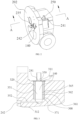
- FIG. 2 is a perspective view of a rear housing in a first embodiment of the present application.
- the rear housing 173 has a housing end surface 202 that is arranged toward the middle housing 172, exhaust ends of the male rotor 102 and the female rotor 103 abut against the housing end surface 202, and the housing end surface 202 can close a terminal end of the compression cavity 105.
- the housing end surface 202 is further provided with an internal exhaust orifice 235, and the compression cavity 105 can be aligned with the internal exhaust orifice 235.
- gas in the compression cavity 105 is continuously compressed until the compression cavity 105 is communicated with the internal exhaust orifice 235, and the gas in the compression cavity 105 enters an exhaust cavity of the compressor through the internal exhaust orifice 235 and is then discharged out of the compressor.
- the fluid channel 140 has an inlet 241 and an outlet 242.
- the outlet 242 is arranged on the housing end surface 202 and can be swept by the exhaust end of the male rotor 102 or the female rotor 103 so as to be communicated with the compression cavity 105.
- the inlet 241 is arranged on an outer surface of the rear housing 173, the inlet 241 is communicated with an external pipeline 250, and the external pipeline 250 is used to connect an economizer system, so that the economizer system can supply a refrigerant into the compression cavity 105 through the fluid channel 140.
- FIG. 3 is a partial cross-sectional view of FIG. 2, and FIG. 3 is a partial view of the rear housing 173 in FIG. 2 that is sectioned in a direction shown as A-A and viewed in a direction shown as an arrow, showing a structure adjacent to the fluid channel 140 in the rear housing 173.
- the fluid channel 140 comprises a first end 311 and a second end 312, the inlet 241 is located at the first end 311, and the outlet 242 is located at the second end 312.
- An area of the inlet 241 is equal to or smaller than a cross-sectional area of the fluid channel 140.
- the fluid channel 140 comprises a front section 351 and a rear section 352, the front section 351 extends in a vertical direction, and the rear section 352 extends in a horizontal direction as shown in FIG. 3 .
- the front section 351 and the rear section 352 are arranged under the premise of convenient machining to adapt to opposite positions of the inlet 241 and the outlet 242 so as to communicate the compression cavity 105 with the external pipeline.
- the arrangement of the position of the inlet 241 is changed, the arrangement of the position and the arrangement of an extension direction of the front section 351 and the rear section 352 of the fluid channel 140 are changed accordingly.
- the first end 311 comprises a top plate 357 with a hole 359 in a middle portion, and the top plate 357 covers an end portion of the first end 311.
- the hole 359 of the top plate 357 forms the inlet 241.
- the inlet 241 is arranged at another position of the rear housing 173, and the fluid channel 140 extends in a same direction.
- an outer side of the front section 351 of the fluid channel 140 is provided with a silencing structure 320 around the front section 351.
- the silencing structure 320 comprises a cavity 308 and a silencing material 371 located in the cavity 308.
- the cavity 308 is communicated with the front section 351.
- the cavity 308 has an inner side 361 and an outer side 362.
- the inner side 361 and the outer side 362 have a certain distance, so that the cavity 308 has a certain thickness in a radial direction of the fluid channel.
- the cavity 308 is generally in an annular shape with a certain thickness.
- the outer side 362 has a side wall formed by the rear housing 173, the inner side 361 has an opening 365, and the opening 365 is communicated with the front section 351 of the fluid channel 140.
- a height of the opening 365 is equal to that of the cavity 308, and the opening 365 extends for a circle in a circumferential direction to form a closed annular shape. That is, an area of the opening 365 is equal to an outer surface area of the front section surrounded by the silencing structure. That is to say, the cavity 308 and the front section 351 of the fluid channel 140 can form an integral space.
- the area of the opening 365 is smaller than the outer surface area of the front section 351 surrounded by the cavity 308.
- the height of the opening 365 is smaller than that of the cavity 308, or the opening 365 extends for less than a circle in a circumferential direction.
- the silencing material 371 is an acoustic material composed of a plurality of acoustic meta-silencing units.
- the acoustic meta-silencing units are resonant cavity type acoustic meta-silencing units.
- Each of the acoustic meta-silencing units has a cavity, and the cavities of the acoustic meta-silencing units can be communicated with the front section 351 of the fluid channel 140.
- the silencing material 371 can absorb the pressure pulsations in the fluid channel 140 to a certain extent to reduce an effect of the pressure pulsations on the external pipeline.
- the silencing units in the silencing material 371 are arranged at a single size or multiple sizes, so that the silencing units can be arranged to silence a sound of a certain hertz (i.e., a certain frequency), or can be used to silence sounds of multiple hertz.
- a certain hertz i.e., a certain frequency
- the silencing structure 320 is arranged close to the inlet 241 of the fluid channel 140, that is, close to a junction between the fluid channel 140 and the external pipeline, to reduce an effect of the pressure pulsations on the external pipeline as much as possible.
- the silencing structure 320 may also be arranged around the entire fluid channel 140, that is, the silencing structure 320 is arranged on an outer side of each section of the fluid channel 140.
- the hollow cavity 308 can absorb the pressure pulsations in the fluid channel 140 to a certain extent.
- FIG. 4 is a partial cross-sectional view of a rear housing in a second embodiment of the present application. Similar to the embodiment shown in FIG. 3 , differences are that a plurality of cavities 408 are arranged in an extension direction of the fluid channel 140, and each of the cavities 408 has a distance from the adjacent cavities 408. Each of the cavities 408 is provided with the silencing material 371, or is an empty cavity. That is to say, the cavities can be intermittently arranged in the extension direction of the fluid channel 140. Compared with the first embodiment in FIG. 3 , the second embodiment in FIG. 4 has similar technical effects.
- the plurality of radial partition walls 518 are arranged in a juxtaposed manner in the axial direction to divide the space 522 into a plurality of segmented spaces 521, and the plurality of axial partition walls 519 are arranged in the radial direction to divide the plurality of segmented spaces 521 into a plurality of cavities 508.
- the plurality of axial partition walls 519 in the adjacent segmented spaces 521 are arranged alternately, so that the plurality of cavities 508 are arranged alternately.
- the inner wall 511 forms a side wall 539 of the silencing structure
- the side wall 539 is provided with a plurality of side wall channels 529 penetrating through the side wall 539, and the plurality of side wall channels 529 can communicate the fluid channel 140 with each of the plurality of cavities 508.
- each of the plurality of cavities 508 has a front end 581 and a rear end 582, the front end 581 is close to the first end 311 of the fluid channel 140, and the rear end 582 is far away from the first end 311 of the fluid channel 140.
- At least one side wall channel of the plurality of side wall channels 529 is close to the rear ends 582 of the cavities 508 to facilitate the introduction of fluid in the cavities 508 back into the fluid channel 140, so that no liquid or a small amount of liquid is accumulated in the fluid channel 140.
- the third embodiment in FIG. 5A has similar technical effects.
- FIG. 6 is an axial cross-sectional view of a silencing structure in a fourth embodiment of the present application. Similar to the embodiment shown in FIG. 5A , differences are that the silencing structure 620 in the fourth embodiment is not provided with an outer wall, and when the silencing structure 620 is mounted on the rear housing 173, the rear housing 173, axial partition walls, an inner wall 611 and radial partition walls 618 together form a plurality of cavities 608.
- the fourth embodiment in FIG. 6 has similar technical effects.
- FIG. 7 is an axial cross-sectional view of a silencing structure in a fifth embodiment of the present application. Similar to the embodiment shown in FIG. 5A , the difference is that bottoms 765 of cavities 708 in the fifth embodiment extend obliquely downward from the outside to the inside. Such design is more conducive to discharging liquid in the cavities 708 to the fluid channel 140, thereby avoiding the accumulation of liquid in the cavities 708.
- the fifth embodiment in FIG. 7 has similar technical effects.
- FIG. 8 is a radial cross-sectional view of a silencing structure in a sixth embodiment of the present application. Similar to the embodiment shown in FIG. 5A , the difference is that an inner wall 811 and an outer wall 812 in the sixth embodiment are not coaxially arranged. That is to say, as seen from a radial cross-section, the inner wall 811 and the outer wall 812 have an unequal distance. Thus, each of cavities 808 is no longer evenly distributed in a circumferential direction.
- the present embodiment is suitable for some situations with specific requirements for the mounting position of the fluid channel 140.
- the sixth embodiment in FIG. 8 has similar technical effects.
- FIG. 9 is a partial cross-sectional view of a rear housing in a seventh embodiment of the present application. Similar to the embodiment shown in FIG. 3 , differences are that a silencing structure in the seventh embodiment in FIG. 9 further comprises a side wall 939, the side wall 939 is generally in a cylindrical shape, and the side wall 939 surrounds at least a section of the fluid channel 140. That is to say, the side wall 939 is arranged between the fluid channel 140 and cavities 908.
- the side wall 939 is provided with a plurality of side wall channels 929 penetrating through the side wall 939, and the plurality of side wall channels 929 can communicate the fluid channel 140 with each of the cavities 908.
- the cavities 908 In the extension direction of the fluid channel 140, the cavities 908 have front ends 981 and rear ends 982, the front ends 981 are close to the first end 311 of the fluid channel 140, and the rear ends 982 are far away from the first end 311 of the fluid channel 140. At least one side wall channel of the plurality of side wall channels 929 is close to the rear ends 982 of the cavities 908 to facilitate the introduction of fluid in the cavities 908 back into the fluid channel 140, so that no liquid or a small amount of liquid is accumulated in the fluid channel 140.
- the silencing structure in the seventh embodiment in FIG. 9 further comprises a top plate 945, and the top plate 945 covers tops of the cavities 908 and the side wall 939 to isolate the cavities 908 from the outside.
- the top plate 945 is provided with a hole 958, and the external pipeline is communicated with the fluid channel through the hole 958.
- the side wall 939 and the top plate 945 are of an integrated structure to facilitate installation.
- the cavities 908 are provided with a silencing material.
- the seventh embodiment in FIG. 9 has similar technical effects.
- Figure 10 is a partial cross-sectional view of a rear housing in an eighth embodiment of the present application. Similar to the embodiment shown in FIG. 9 , differences are that a plurality of cavities 1008 are arranged in the extension direction of the fluid channel 140, and each of the cavities 1008 has a distance from the adjacent cavities 1008. That is to say, the cavities can be intermittently arranged in the extension direction of the fluid channel 140. Compared with the first embodiment in FIG. 3 , the eighth embodiment in FIG. 10 has similar technical effects.
- FIG. 11 is a partial cross-sectional view of a rear housing in a ninth embodiment of the present application. Similar to the embodiment shown in FIG. 9 , differences are that cavities 1108 are not provided with a silencing material and are empty cavities. Compared with the embodiment in FIG. 9 , the ninth embodiment in FIG. 11 has similar technical effects.
- FIG. 12 is a partial cross-sectional view of a rear housing in a tenth embodiment of the present application. Similar to the embodiment shown in FIG. 10 , differences are that cavities 1208 are not provided with a silencing material and are empty cavities. Compared with the embodiment in FIG. 10 , the ninth embodiment in FIG. 12 has similar technical effects.
- the fluid channel in the present application can introduce a refrigerant in an economizer into the compression cavity.
- the teeth of the rotors periodically sweep through the outlet of the fluid channel, that is, a communication port between the fluid channel and the compression cavity. Since pressures in tooth slots on two sides of the teeth of the screw rotors are different, the pressure of fluid in the fluid channel is constantly changed, leading to vibration and noise. Changes of the pressure are transmitted to the external pipeline that connects the economizer system with the fluid channel of the compressor, which may cause joint loosening or breaking of the external pipeline.
- the silencing structure is arranged on an outer side of the fluid channel in the present application, which can absorb at least a part of the pressure fluctuations, reduce noise, and reduce an effect of pressure changes on the external pipeline of the economizer system.
Landscapes
- Engineering & Computer Science (AREA)
- Mechanical Engineering (AREA)
- General Engineering & Computer Science (AREA)
- Applications Or Details Of Rotary Compressors (AREA)
Abstract
Description
- The present application provides a screw compressor, especially a screw compressor with a silencing structure.
- A twin-screw compressor has a pair of male and female rotors that can be meshed with each other, and a refrigerant is compressed by opposite rotation of the pair of male and female rotors. The twin-screw compressor is communicated with an economizer system, and the economizer system provides a part of the refrigerant (or other media) to the inside of the compressor to improve the capacity of the twin-screw compressor. The economizer system is communicated with a compression cavity of the compressor through a pipeline.
- The present application provides a screw compressor, comprising: a housing, a fluid channel, and a silencing structure. The housing is provided with a compression cavity; the fluid channel is located in the housing, a first end of the fluid channel is communicated with the outside of the compressor, and a second end of the fluid channel is communicated with the compression cavity; the silencing structure is arranged on an outer side of the fluid channel, the silencing structure comprises at least one cavity, and the at least one cavity is communicated with the fluid channel.
- In the screw compressor as described above, the at least one cavity is arranged in an annular shape surrounding the fluid channel.
- In the screw compressor as described above, the at least one cavity is arranged around a portion of the fluid channel.
- In the screw compressor as described above, the at least one cavity comprises a plurality of chambers, and the plurality of chambers are arranged in an extension direction of the fluid channel.
- In the screw compressor as described above, the at least one cavity comprises a plurality of chambers, and the plurality of chambers are arranged alternately in the extension direction of the fluid channel.
- In the screw compressor as described above, the silencing structure further comprises a silencing material, and the silencing material is filled in the at least one cavity.
- In the screw compressor as described above, the silencing material comprises a plurality of acoustic meta-silencing units, and at least a portion of the plurality of acoustic meta-silencing units are communicated with the fluid channel.
- In the screw compressor as described above, the silencing structure further comprises a side wall, the side wall is arranged around the fluid channel and is located between the fluid channel and the at least one cavity, the side wall is provided with a plurality of side wall channels, and the side wall channels penetrate through the side wall to communicate the at least one cavity with the fluid channel.
- In the screw compressor as described above, in an extending direction of the fluid channel, the at least one cavity has a front end and a rear end, the front end is close to the first end of the fluid channel, and the rear end is far away from the first end of the fluid channel; at least one side wall channel of the plurality of side wall channels is close to the rear end of the at least one cavity.
- In the screw compressor as described above, the silencing structure is close to the first end of the fluid channel, and the first end of the fluid channel is communicated with an economizer of an air conditioning system.
- The screw compressor in the present application is internally provided with the fluid channel that can communicate the compression cavity with an external economizer system. The fluid channel can introduce a refrigerant in the economizer into the compression cavity. Since teeth of rotors periodically sweep through an outlet of the fluid channel during operation of the screw compressor, pressures in tooth slots on two sides of the teeth of the rotors are different, resulting in constant pressure changes of fluid in the fluid channel, which may cause joint loosening or breaking of a pipeline connected to the economizer system due to vibration. The silencing structure is arranged at the fluid channel in the present application, so that an effect of pressure changes on an external pipeline of the economizer system can be reduced.
-
-
FIG. 1A is a perspective view of a compressor in the present application; -
FIG. 1B is a cross-sectional view of the compressor inFIG. 1A ; -
FIG. 2 is a perspective view of a rear housing in a first embodiment of the present application; -
FIG. 3 is a partial cross-sectional view ofFIG. 2 ; -
FIG. 4 is a partial cross-sectional view of a rear housing in a second embodiment of the present application; -
FIG. 5A is a perspective view of a silencing structure in a third embodiment of the present application; -
FIG. 5B is a bottom view of the silencing structure inFIG. 5A viewed in an axial direction; -
FIG. 5C is an axial cross-sectional view of the silencing structure sectioned along a B-B line inFIG. 5B ; -
FIG. 5D is an axial cross-sectional view of the silencing structure sectioned along a C-C line inFIG. 5B ; -
FIG. 6 is an axial cross-sectional view of a silencing structure in a fourth embodiment of the present application; -
FIG. 7 is an axial cross-sectional view of a silencing structure in a fifth embodiment of the present application; -
FIG. 8 is a radial cross-sectional view of a silencing structure in a sixth embodiment of the present application; -
FIG. 9 is a partial cross-sectional view of a rear housing in a seventh embodiment of the present application; -
FIG. 10 is a partial cross-sectional view of a rear housing in an eighth embodiment of the present application; -
FIG. 11 is a partial cross-sectional view of a rear housing in a ninth embodiment of the present application; -
FIG. 12 is a partial cross-sectional view of a rear housing in a tenth embodiment of the present application. - Various specific embodiments of the present application will be described below with reference to the drawings that constitute a part of the specification. It should be understood that although terms used to indicate direction in the present application, such as "front", "rear", "upper", "lower", "left", "right", etc., are used to describe various exemplary structural portions and elements of the present application, these terms are used herein solely for the purpose of convenient explanation, which are determined based on exemplary orientations shown in the drawings. Since the embodiments disclosed in the present application can be arranged in different directions, these terms indicating directions are used only for illustration and should not be regarded as limitations.
-
FIG. 1A is a perspective view of a compressor in the present application.FIG. 1B is a cross-sectional view of the compressor inFIG. 1A . Thecompressor 100 comprises ahousing 101 and amale rotor 102 and afemale rotor 103 that are located in thehousing 101. Themale rotor 102 and thefemale rotor 103 can be driven to rotate. Themale rotor 102 is in transmission connection with amotor 160, so that themotor 160 can drive themale rotor 102 to rotate around an axis of themale rotor 102 relative to thehousing 101. Thefemale rotor 103 can be driven by themale rotor 102 to rotate around an axis of thefemale rotor 103 relative to thehousing 101. An outer side of themale rotor 102 has a plurality ofspiral teeth 168 and spiral grooves formed between theadjacent teeth 168, and an outer side of thefemale rotor 103 also has a plurality ofspiral teeth 169 and spiral grooves formed between theadjacent teeth 169. Theteeth 168 and grooves of themale rotor 102 and the grooves andteeth 169 of thefemale rotor 103 form an intermeshing structure, so that themale rotor 102, thefemale rotor 103 and thehousing 101 together form acompression cavity 105. Afluid channel 140 is arranged in thehousing 101 and is used for providing a refrigerant into thecompression cavity 105 of thecompressor 100. - The
housing 101 comprises afront housing 171, amiddle housing 172, and arear housing 173. Thefront housing 171, themiddle housing 172 and therear housing 173 are connected in sequence. Fluid flows from thefront housing 171 to therear housing 173 in the compressor. Thefluid channel 140 is located on therear housing 173. An outlet of thefluid channel 140 is communicated with thecompression cavity 105, an inlet of the fluid channel is connected to an economizer system through a pipeline, and the economizer system introduces a part of the refrigerant in a refrigeration cycle system back to the compressor to improve the capacity of the compressor. For example, the economizer system communicates thefluid channel 140 with a bottom of a condenser or a subcooler and introduces a small part of the refrigerant liquid from the bottom of the condenser or the subcooler back to the compressor, and this part of the refrigerant liquid can enter the compressor using a natural pressure difference. In the screw compressor, the teeth of themale rotor 102 or thefemale rotor 103 periodically pass through the outlet of thefluid channel 140. Since pressures in tooth slots on two sides of the teeth of the rotors are obviously different, the pressure at the outlet of thefluid channel 140 is changed to a certain extent. Complex flow regime and pressure pulsations present in thefluid channel 140 may lead to the risk of joint loosening or breaking of a pipeline connected to the economizer system due to vibration. A silencing structure is arranged at thefluid channel 140 in the present application, which can reduce the amplitude of the pressure pulsations, thereby reducing an effect of the pressure pulsations on an external pipeline. -
FIG. 2 is a perspective view of a rear housing in a first embodiment of the present application. As shown inFIG. 2 , therear housing 173 has ahousing end surface 202 that is arranged toward themiddle housing 172, exhaust ends of themale rotor 102 and thefemale rotor 103 abut against thehousing end surface 202, and thehousing end surface 202 can close a terminal end of thecompression cavity 105. Thehousing end surface 202 is further provided with aninternal exhaust orifice 235, and thecompression cavity 105 can be aligned with theinternal exhaust orifice 235. During rotation of themale rotor 102 and thefemale rotor 103, gas in thecompression cavity 105 is continuously compressed until thecompression cavity 105 is communicated with theinternal exhaust orifice 235, and the gas in thecompression cavity 105 enters an exhaust cavity of the compressor through theinternal exhaust orifice 235 and is then discharged out of the compressor. Thefluid channel 140 has aninlet 241 and anoutlet 242. Theoutlet 242 is arranged on thehousing end surface 202 and can be swept by the exhaust end of themale rotor 102 or thefemale rotor 103 so as to be communicated with thecompression cavity 105. Theinlet 241 is arranged on an outer surface of therear housing 173, theinlet 241 is communicated with anexternal pipeline 250, and theexternal pipeline 250 is used to connect an economizer system, so that the economizer system can supply a refrigerant into thecompression cavity 105 through thefluid channel 140. -
FIG. 3 is a partial cross-sectional view ofFIG. 2, and FIG. 3 is a partial view of therear housing 173 inFIG. 2 that is sectioned in a direction shown as A-A and viewed in a direction shown as an arrow, showing a structure adjacent to thefluid channel 140 in therear housing 173. Thefluid channel 140 comprises afirst end 311 and asecond end 312, theinlet 241 is located at thefirst end 311, and theoutlet 242 is located at thesecond end 312. An area of theinlet 241 is equal to or smaller than a cross-sectional area of thefluid channel 140. In one embodiment of the present application, thefluid channel 140 comprises afront section 351 and arear section 352, thefront section 351 extends in a vertical direction, and therear section 352 extends in a horizontal direction as shown inFIG. 3 . In the present application, thefront section 351 and therear section 352 are arranged under the premise of convenient machining to adapt to opposite positions of theinlet 241 and theoutlet 242 so as to communicate thecompression cavity 105 with the external pipeline. When the arrangement of the position of theinlet 241 is changed, the arrangement of the position and the arrangement of an extension direction of thefront section 351 and therear section 352 of thefluid channel 140 are changed accordingly. - In one embodiment of the present application, the
first end 311 comprises atop plate 357 with ahole 359 in a middle portion, and thetop plate 357 covers an end portion of thefirst end 311. Thehole 359 of thetop plate 357 forms theinlet 241. - In another embodiment of the present application, the
inlet 241 is arranged at another position of therear housing 173, and thefluid channel 140 extends in a same direction. - As shown in
FIG. 3 , an outer side of thefront section 351 of thefluid channel 140 is provided with a silencingstructure 320 around thefront section 351. The silencingstructure 320 comprises acavity 308 and a silencingmaterial 371 located in thecavity 308. Thecavity 308 is communicated with thefront section 351. Thecavity 308 has aninner side 361 and anouter side 362. Theinner side 361 and theouter side 362 have a certain distance, so that thecavity 308 has a certain thickness in a radial direction of the fluid channel. Thecavity 308 is generally in an annular shape with a certain thickness. In one embodiment of the present application, theouter side 362 has a side wall formed by therear housing 173, theinner side 361 has anopening 365, and theopening 365 is communicated with thefront section 351 of thefluid channel 140. In one embodiment of the present application, a height of theopening 365 is equal to that of thecavity 308, and theopening 365 extends for a circle in a circumferential direction to form a closed annular shape. That is, an area of theopening 365 is equal to an outer surface area of the front section surrounded by the silencing structure. That is to say, thecavity 308 and thefront section 351 of thefluid channel 140 can form an integral space. In another embodiment of the present application, the area of theopening 365 is smaller than the outer surface area of thefront section 351 surrounded by thecavity 308. For example, the height of theopening 365 is smaller than that of thecavity 308, or theopening 365 extends for less than a circle in a circumferential direction. - The silencing
material 371 is an acoustic material composed of a plurality of acoustic meta-silencing units. The acoustic meta-silencing units are resonant cavity type acoustic meta-silencing units. Each of the acoustic meta-silencing units has a cavity, and the cavities of the acoustic meta-silencing units can be communicated with thefront section 351 of thefluid channel 140. The silencingmaterial 371 can absorb the pressure pulsations in thefluid channel 140 to a certain extent to reduce an effect of the pressure pulsations on the external pipeline. - The silencing units in the silencing
material 371 are arranged at a single size or multiple sizes, so that the silencing units can be arranged to silence a sound of a certain hertz (i.e., a certain frequency), or can be used to silence sounds of multiple hertz. - In the present embodiment, the silencing
structure 320 is arranged close to theinlet 241 of thefluid channel 140, that is, close to a junction between thefluid channel 140 and the external pipeline, to reduce an effect of the pressure pulsations on the external pipeline as much as possible. In another embodiment of the present application, the silencingstructure 320 may also be arranged around the entirefluid channel 140, that is, the silencingstructure 320 is arranged on an outer side of each section of thefluid channel 140. - It should be noted that in the present embodiment, even when the silencing
material 371 is not arranged in thecavity 308, thehollow cavity 308 can absorb the pressure pulsations in thefluid channel 140 to a certain extent. -
FIG. 4 is a partial cross-sectional view of a rear housing in a second embodiment of the present application. Similar to the embodiment shown inFIG. 3 , differences are that a plurality ofcavities 408 are arranged in an extension direction of thefluid channel 140, and each of thecavities 408 has a distance from theadjacent cavities 408. Each of thecavities 408 is provided with the silencingmaterial 371, or is an empty cavity. That is to say, the cavities can be intermittently arranged in the extension direction of thefluid channel 140. Compared with the first embodiment inFIG. 3 , the second embodiment inFIG. 4 has similar technical effects. -
FIG. 5A is a perspective view of a silencing structure in a third embodiment of the present application;FIG. 5B is a bottom view of the silencing structure inFIG. 5A viewed in an axial direction;FIG. 5C is an axial cross-sectional view of the silencing structure sectioned along a B-B line inFIG. 5B ; andFIG. 5D is an axial cross-sectional view of the silencing structure sectioned along a C-C line inFIG. 5B . Wherein, a cross-section inFIG. 5B is shown inFIG. 5A andFIG. 5B . The silencingstructure 520 is generally in a cylindrical shape and has an axial direction and a radial direction. The silencingstructure 520 has aninner wall 511 and anouter wall 512. At least a section of thefluid channel 140 is surrounded by theinner wall 511. For example, thefront section 351 of thefluid channel 140 is surrounded by theinner wall 511. Theouter wall 512 is connected to therear housing 173. Aspace 522 is formed between theinner wall 511 and theouter wall 512. A plurality ofradial partition walls 518 extending in the radial direction and a plurality ofaxial partition walls 519 extending in the axial direction are arranged between theinner wall 511 and theouter wall 512. The plurality ofradial partition walls 518 are arranged in a juxtaposed manner in the axial direction to divide thespace 522 into a plurality ofsegmented spaces 521, and the plurality ofaxial partition walls 519 are arranged in the radial direction to divide the plurality ofsegmented spaces 521 into a plurality ofcavities 508. The plurality ofaxial partition walls 519 in the adjacentsegmented spaces 521 are arranged alternately, so that the plurality ofcavities 508 are arranged alternately. - Wherein, the
inner wall 511 forms aside wall 539 of the silencing structure, theside wall 539 is provided with a plurality ofside wall channels 529 penetrating through theside wall 539, and the plurality ofside wall channels 529 can communicate thefluid channel 140 with each of the plurality ofcavities 508. Wherein, in the extension direction of thefluid channel 140, each of the plurality ofcavities 508 has afront end 581 and arear end 582, thefront end 581 is close to thefirst end 311 of thefluid channel 140, and therear end 582 is far away from thefirst end 311 of thefluid channel 140. At least one side wall channel of the plurality ofside wall channels 529 is close to the rear ends 582 of thecavities 508 to facilitate the introduction of fluid in thecavities 508 back into thefluid channel 140, so that no liquid or a small amount of liquid is accumulated in thefluid channel 140. - Compared with the first embodiment in
FIG. 3 , the third embodiment inFIG. 5A has similar technical effects. -
FIG. 6 is an axial cross-sectional view of a silencing structure in a fourth embodiment of the present application. Similar to the embodiment shown inFIG. 5A , differences are that the silencingstructure 620 in the fourth embodiment is not provided with an outer wall, and when the silencingstructure 620 is mounted on therear housing 173, therear housing 173, axial partition walls, aninner wall 611 andradial partition walls 618 together form a plurality ofcavities 608. - Compared with the third embodiment in
FIG. 5A , the fourth embodiment inFIG. 6 has similar technical effects. -
FIG. 7 is an axial cross-sectional view of a silencing structure in a fifth embodiment of the present application. Similar to the embodiment shown inFIG. 5A , the difference is thatbottoms 765 ofcavities 708 in the fifth embodiment extend obliquely downward from the outside to the inside. Such design is more conducive to discharging liquid in thecavities 708 to thefluid channel 140, thereby avoiding the accumulation of liquid in thecavities 708. - Compared with the third embodiment in
FIG. 5A , the fifth embodiment inFIG. 7 has similar technical effects. -
FIG. 8 is a radial cross-sectional view of a silencing structure in a sixth embodiment of the present application. Similar to the embodiment shown inFIG. 5A , the difference is that aninner wall 811 and anouter wall 812 in the sixth embodiment are not coaxially arranged. That is to say, as seen from a radial cross-section, theinner wall 811 and theouter wall 812 have an unequal distance. Thus, each ofcavities 808 is no longer evenly distributed in a circumferential direction. The present embodiment is suitable for some situations with specific requirements for the mounting position of thefluid channel 140. - Compared with the third embodiment in
FIG. 5A , the sixth embodiment inFIG. 8 has similar technical effects. -
FIG. 9 is a partial cross-sectional view of a rear housing in a seventh embodiment of the present application. Similar to the embodiment shown inFIG. 3 , differences are that a silencing structure in the seventh embodiment inFIG. 9 further comprises aside wall 939, theside wall 939 is generally in a cylindrical shape, and theside wall 939 surrounds at least a section of thefluid channel 140. That is to say, theside wall 939 is arranged between thefluid channel 140 andcavities 908. Theside wall 939 is provided with a plurality ofside wall channels 929 penetrating through theside wall 939, and the plurality ofside wall channels 929 can communicate thefluid channel 140 with each of thecavities 908. In the extension direction of thefluid channel 140, thecavities 908 havefront ends 981 andrear ends 982, the front ends 981 are close to thefirst end 311 of thefluid channel 140, and the rear ends 982 are far away from thefirst end 311 of thefluid channel 140. At least one side wall channel of the plurality ofside wall channels 929 is close to the rear ends 982 of thecavities 908 to facilitate the introduction of fluid in thecavities 908 back into thefluid channel 140, so that no liquid or a small amount of liquid is accumulated in thefluid channel 140. - The silencing structure in the seventh embodiment in
FIG. 9 further comprises atop plate 945, and thetop plate 945 covers tops of thecavities 908 and theside wall 939 to isolate thecavities 908 from the outside. Thetop plate 945 is provided with ahole 958, and the external pipeline is communicated with the fluid channel through thehole 958. In one embodiment of the present application, theside wall 939 and thetop plate 945 are of an integrated structure to facilitate installation. - Similar to the embodiment shown in
FIG. 3 , thecavities 908 are provided with a silencing material. Compared with the first embodiment inFIG. 3 , the seventh embodiment inFIG. 9 has similar technical effects. -
Figure 10 is a partial cross-sectional view of a rear housing in an eighth embodiment of the present application. Similar to the embodiment shown inFIG. 9 , differences are that a plurality ofcavities 1008 are arranged in the extension direction of thefluid channel 140, and each of thecavities 1008 has a distance from theadjacent cavities 1008. That is to say, the cavities can be intermittently arranged in the extension direction of thefluid channel 140. Compared with the first embodiment inFIG. 3 , the eighth embodiment inFIG. 10 has similar technical effects. -
FIG. 11 is a partial cross-sectional view of a rear housing in a ninth embodiment of the present application. Similar to the embodiment shown inFIG. 9 , differences are thatcavities 1108 are not provided with a silencing material and are empty cavities. Compared with the embodiment inFIG. 9 , the ninth embodiment inFIG. 11 has similar technical effects. -
FIG. 12 is a partial cross-sectional view of a rear housing in a tenth embodiment of the present application. Similar to the embodiment shown inFIG. 10 , differences are thatcavities 1208 are not provided with a silencing material and are empty cavities. Compared with the embodiment inFIG. 10 , the ninth embodiment inFIG. 12 has similar technical effects. - The fluid channel in the present application can introduce a refrigerant in an economizer into the compression cavity. During operation of the screw compressor, the teeth of the rotors periodically sweep through the outlet of the fluid channel, that is, a communication port between the fluid channel and the compression cavity. Since pressures in tooth slots on two sides of the teeth of the screw rotors are different, the pressure of fluid in the fluid channel is constantly changed, leading to vibration and noise. Changes of the pressure are transmitted to the external pipeline that connects the economizer system with the fluid channel of the compressor, which may cause joint loosening or breaking of the external pipeline. The silencing structure is arranged on an outer side of the fluid channel in the present application, which can absorb at least a part of the pressure fluctuations, reduce noise, and reduce an effect of pressure changes on the external pipeline of the economizer system.
- Although the present disclosure has been described in conjunction with examples of the embodiments as summarized above, various alternatives, modifications, variations, improvements and/or substantial equivalents, whether known, present, or foreseeable in the near future, may be apparent to those of at least ordinary skill in the art. In addition, technical effects and/or technical problems described in the specification are illustrative rather than restrictive. Thus, the disclosure in the specification may be used to solve other technical problems and/or have other technical effects. Therefore, the examples of the embodiments of the present disclosure as described above are intended to be illustrative rather than restrictive. Various changes may be made without departing from the spirit or scope of the present disclosure. Therefore, the present disclosure is intended to comprise all known or earlier developed alternatives, modifications, variations, improvements and/or substantial equivalents.
Claims (10)
- A screw compressor, comprising:a housing (101), wherein the housing (101) is provided with a compression cavity (105);a fluid channel (140), wherein the fluid channel (140) is located in the housing, a first end (311) of the fluid channel (140) is communicated with the outside of the compressor, and a second end (312) of the fluid channel (140) is communicated with the compression cavity (105);a silencing structure, wherein the silencing structure is arranged on an outer side of the fluid channel (140), the silencing structure comprises at least one cavity, and the at least one cavity is communicated with the fluid channel (140).
- The screw compressor of claim 1, wherein:
the at least one cavity is arranged in an annular shape surrounding the fluid channel (140). - The screw compressor of claim 1, wherein:
the at least one cavity is arranged around a portion of the fluid channel (140). - The screw compressor of claim 1, wherein:
the at least one cavity comprises a plurality of chambers, and the plurality of chambers are arranged in an extension direction of the fluid channel (140). - The screw compressor of claim 4, wherein:
the at least one cavity comprises a plurality of chambers, and the plurality of chambers are arranged alternately in the extension direction of the fluid channel (140). - The screw compressor of claim 1, wherein:
the silencing structure further comprises a silencing material, and the silencing material is filled in the at least one cavity. - The screw compressor of claim 6, wherein:
the silencing material comprises a plurality of acoustic meta-silencing units, and at least a portion of the plurality of acoustic meta-silencing units are communicated with the fluid channel (140). - The screw compressor of claim 1, wherein:
the silencing structure further comprises a side wall (939), the side wall (939) is arranged around the fluid channel (140) and is located between the fluid channel (140) and the at least one cavity, the side wall (939) is provided with a plurality of side wall channels (929), and the side wall channels (929) penetrate through the side wall (939) to communicate the at least one cavity with the fluid channel (140). - The screw compressor of claim 8, wherein:in an extension direction of the fluid channel (140), the at least one cavity has a front end (981) and a rear end (982), the front end (981) is close to the first end of the fluid channel (140), and the rear end (982) is far away from the first end of the fluid channel (140);at least one side wall channel of the plurality of side wall channels (929) is close to the rear end (982) of the at least one cavity.
- The screw compressor of claim 1, wherein:
the silencing structure is close to the first end (311) of the fluid channel (140), and the first end (311) of the fluid channel (140) is communicated with an economizer of an air conditioning system.
Applications Claiming Priority (2)
| Application Number | Priority Date | Filing Date | Title |
|---|---|---|---|
| CN202210982105.6A CN115324892A (en) | 2022-08-16 | 2022-08-16 | Screw compressor |
| PCT/CN2023/110529 WO2024037331A1 (en) | 2022-08-16 | 2023-08-01 | Screw compressor |
Publications (2)
| Publication Number | Publication Date |
|---|---|
| EP4575231A1 true EP4575231A1 (en) | 2025-06-25 |
| EP4575231A4 EP4575231A4 (en) | 2026-07-15 |
Family
ID=83924096
Family Applications (1)
| Application Number | Title | Priority Date | Filing Date |
|---|---|---|---|
| EP23854235.1A Pending EP4575231A4 (en) | 2022-08-16 | 2023-08-01 | Screw compressor |
Country Status (4)
| Country | Link |
|---|---|
| EP (1) | EP4575231A4 (en) |
| CN (1) | CN115324892A (en) |
| TW (1) | TW202409425A (en) |
| WO (1) | WO2024037331A1 (en) |
Families Citing this family (4)
| Publication number | Priority date | Publication date | Assignee | Title |
|---|---|---|---|---|
| CN115324892A (en) * | 2022-08-16 | 2022-11-11 | 江森自控空调冷冻设备(无锡)有限公司 | Screw compressor |
| CN117514812A (en) * | 2023-11-09 | 2024-02-06 | 珠海格力电器股份有限公司 | A kind of silencer structure and compressor |
| CN119616860A (en) * | 2024-12-17 | 2025-03-14 | 珠海格力电器股份有限公司 | Compressor and control method thereof |
| US20260194052A1 (en) * | 2025-01-03 | 2026-07-09 | Trane International Inc. | Pressure pulsation muffling device |
Family Cites Families (15)
| Publication number | Priority date | Publication date | Assignee | Title |
|---|---|---|---|---|
| KR100504983B1 (en) * | 2003-03-12 | 2005-08-01 | 삼성광주전자 주식회사 | A suction muffler for compressor, A compressor and A apparatus having refrigerant cycle circuit |
| CN101137840B (en) * | 2005-03-07 | 2010-06-23 | 开利公司 | Compressor Noise Suppression |
| EP2216579B1 (en) * | 2009-02-04 | 2012-04-18 | FESTO AG & Co. KG | Compressed air acoustic dampening system |
| DE102012102349A1 (en) * | 2012-03-20 | 2013-09-26 | Bitzer Kühlmaschinenbau Gmbh | Refrigerant compressor |
| CN203742974U (en) * | 2014-02-14 | 2014-07-30 | 厦门鹏诚灏工贸有限公司 | Silencing device arranged on dynamic compressor |
| DE102015202851A1 (en) * | 2015-02-17 | 2016-08-18 | Röchling Automotive SE & Co. KG | Fluid conduit means |
| CN204612124U (en) * | 2015-04-23 | 2015-09-02 | 长城汽车股份有限公司 | Silencing apparatus, air-conditioning system and vehicle |
| CN207004830U (en) * | 2017-06-20 | 2018-02-13 | 苏州艾柏特精密机械有限公司 | A kind of inverter screw compressor gas attenuator |
| CN207093249U (en) * | 2017-06-27 | 2018-03-13 | 宁波远景汽车零部件有限公司 | Compound air inlet resonant cavity and automobile |
| CN208010597U (en) * | 2018-02-08 | 2018-10-26 | 珠海格力电器股份有限公司 | Pressure pulsation attenuation device, compressor and air conditioner |
| IT201900018902A1 (en) * | 2019-10-15 | 2021-04-15 | Daikin Applied Europe S P A | SCREW COMPRESSOR |
| CN110805558A (en) * | 2019-10-24 | 2020-02-18 | 珠海格力节能环保制冷技术研究中心有限公司 | Silencer, compressor and air conditioner |
| CN113513474B (en) * | 2020-04-09 | 2023-02-21 | 江森自控空调冷冻设备(无锡)有限公司 | Screw compressor, refrigeration system and control method of refrigeration system |
| CN112628517B (en) * | 2020-12-11 | 2023-06-02 | 南京光声超构材料研究院有限公司 | Pipe muffler, device and preparation method |
| CN115324892A (en) * | 2022-08-16 | 2022-11-11 | 江森自控空调冷冻设备(无锡)有限公司 | Screw compressor |
-
2022
- 2022-08-16 CN CN202210982105.6A patent/CN115324892A/en active Pending
-
2023
- 2023-08-01 EP EP23854235.1A patent/EP4575231A4/en active Pending
- 2023-08-01 WO PCT/CN2023/110529 patent/WO2024037331A1/en not_active Ceased
- 2023-08-08 TW TW112129790A patent/TW202409425A/en unknown
Also Published As
| Publication number | Publication date |
|---|---|
| TW202409425A (en) | 2024-03-01 |
| WO2024037331A1 (en) | 2024-02-22 |
| CN115324892A (en) | 2022-11-11 |
| EP4575231A4 (en) | 2026-07-15 |
Similar Documents
| Publication | Publication Date | Title |
|---|---|---|
| WO2024037331A1 (en) | Screw compressor | |
| CN104411974B (en) | Scroll compressor | |
| EP3376035B1 (en) | Rotary compressor | |
| EP4707603A1 (en) | Screw compressor | |
| CN116591962A (en) | Screw compressors | |
| CN115492763A (en) | Screw compressors | |
| US20050106054A1 (en) | Compressor discharge chamber with baffle plate | |
| WO2024169977A1 (en) | Screw compressor | |
| CN210599406U (en) | Compressor and air conditioning unit | |
| JPH0368237B2 (en) | ||
| CN110541824A (en) | Compressor and air conditioning unit | |
| CN111878403B (en) | Compressor air supply mechanism, compressor and compressor air supply method | |
| WO2025195071A1 (en) | Silencing device | |
| CN212536070U (en) | Novel swing rotor compressor with low-pressure cavity in shell | |
| CN100535442C (en) | Oil pump of scroll compressor | |
| CN101778999B (en) | Screw compressor with integral bearing cover and discharge plenum divider | |
| CN119594012A (en) | Compressor with a compressor body having a rotor with a rotor shaft | |
| CN108916055B (en) | Compressor and air conditioner | |
| CN217055583U (en) | Scroll compressor having a discharge port for discharging refrigerant from a discharge chamber | |
| CN119825678A (en) | Muffler, compressor and refrigeration equipment | |
| CN1869443A (en) | Refrigerant compressor | |
| CN116838571A (en) | Electric compressor, air conditioning system and vehicle | |
| CN116838570A (en) | Electric compressor, air conditioning system and vehicle | |
| CN109690083B (en) | Scroll compressor having a plurality of scroll members | |
| CN201599191U (en) | Rotary compressors and refrigeration cycle devices |
Legal Events
| Date | Code | Title | Description |
|---|---|---|---|
| STAA | Information on the status of an ep patent application or granted ep patent |
Free format text: STATUS: THE INTERNATIONAL PUBLICATION HAS BEEN MADE |
|
| PUAI | Public reference made under article 153(3) epc to a published international application that has entered the european phase |
Free format text: ORIGINAL CODE: 0009012 |
|
| STAA | Information on the status of an ep patent application or granted ep patent |
Free format text: STATUS: REQUEST FOR EXAMINATION WAS MADE |
|
| 17P | Request for examination filed |
Effective date: 20250310 |
|
| AK | Designated contracting states |
Kind code of ref document: A1 Designated state(s): AL AT BE BG CH CY CZ DE DK EE ES FI FR GB GR HR HU IE IS IT LI LT LU LV MC ME MK MT NL NO PL PT RO RS SE SI SK SM TR |
|
| DAV | Request for validation of the european patent (deleted) | ||
| DAX | Request for extension of the european patent (deleted) | ||
| A4 | Supplementary search report drawn up and despatched |
Effective date: 20260610 |
|
| RIC1 | Information provided on ipc code assigned before grant |
Ipc: F04C 29/06 20060101AFI20260609BHEP Ipc: F04C 29/12 20060101ALI20260609BHEP Ipc: F04C 29/00 20060101ALI20260609BHEP Ipc: F04C 18/16 20060101ALI20260609BHEP |