EP4575229A1 - Positive displacement pump system - Google Patents
Positive displacement pump system Download PDFInfo
- Publication number
- EP4575229A1 EP4575229A1 EP24215292.4A EP24215292A EP4575229A1 EP 4575229 A1 EP4575229 A1 EP 4575229A1 EP 24215292 A EP24215292 A EP 24215292A EP 4575229 A1 EP4575229 A1 EP 4575229A1
- Authority
- EP
- European Patent Office
- Prior art keywords
- positive displacement
- displacement pump
- pump
- rotor
- gear
- Prior art date
- Legal status (The legal status is an assumption and is not a legal conclusion. Google has not performed a legal analysis and makes no representation as to the accuracy of the status listed.)
- Pending
Links
Images



Classifications
-
- F—MECHANICAL ENGINEERING; LIGHTING; HEATING; WEAPONS; BLASTING
- F04—POSITIVE - DISPLACEMENT MACHINES FOR LIQUIDS; PUMPS FOR LIQUIDS OR ELASTIC FLUIDS
- F04C—ROTARY-PISTON, OR OSCILLATING-PISTON, POSITIVE-DISPLACEMENT MACHINES FOR LIQUIDS; ROTARY-PISTON, OR OSCILLATING-PISTON, POSITIVE-DISPLACEMENT PUMPS
- F04C11/00—Combinations of two or more machines or pumps, each being of rotary-piston or oscillating-piston type; Pumping installations
- F04C11/001—Combinations of two or more machines or pumps, each being of rotary-piston or oscillating-piston type; Pumping installations of similar working principle
-
- F—MECHANICAL ENGINEERING; LIGHTING; HEATING; WEAPONS; BLASTING
- F04—POSITIVE - DISPLACEMENT MACHINES FOR LIQUIDS; PUMPS FOR LIQUIDS OR ELASTIC FLUIDS
- F04C—ROTARY-PISTON, OR OSCILLATING-PISTON, POSITIVE-DISPLACEMENT MACHINES FOR LIQUIDS; ROTARY-PISTON, OR OSCILLATING-PISTON, POSITIVE-DISPLACEMENT PUMPS
- F04C15/00—Component parts, details or accessories of machines, pumps or pumping installations, not provided for in groups F04C2/00 - F04C14/00
- F04C15/0057—Driving elements, brakes, couplings, transmission specially adapted for machines or pumps
- F04C15/0061—Means for transmitting movement from the prime mover to driven parts of the pump, e.g. clutches, couplings, transmissions
-
- F—MECHANICAL ENGINEERING; LIGHTING; HEATING; WEAPONS; BLASTING
- F04—POSITIVE - DISPLACEMENT MACHINES FOR LIQUIDS; PUMPS FOR LIQUIDS OR ELASTIC FLUIDS
- F04C—ROTARY-PISTON, OR OSCILLATING-PISTON, POSITIVE-DISPLACEMENT MACHINES FOR LIQUIDS; ROTARY-PISTON, OR OSCILLATING-PISTON, POSITIVE-DISPLACEMENT PUMPS
- F04C15/00—Component parts, details or accessories of machines, pumps or pumping installations, not provided for in groups F04C2/00 - F04C14/00
- F04C15/0057—Driving elements, brakes, couplings, transmission specially adapted for machines or pumps
- F04C15/0061—Means for transmitting movement from the prime mover to driven parts of the pump, e.g. clutches, couplings, transmissions
- F04C15/0073—Couplings between rotors and input or output shafts acting by interengaging or mating parts, i.e. positive coupling of rotor and shaft
-
- F—MECHANICAL ENGINEERING; LIGHTING; HEATING; WEAPONS; BLASTING
- F04—POSITIVE - DISPLACEMENT MACHINES FOR LIQUIDS; PUMPS FOR LIQUIDS OR ELASTIC FLUIDS
- F04C—ROTARY-PISTON, OR OSCILLATING-PISTON, POSITIVE-DISPLACEMENT MACHINES FOR LIQUIDS; ROTARY-PISTON, OR OSCILLATING-PISTON, POSITIVE-DISPLACEMENT PUMPS
- F04C2/00—Rotary-piston machines or pumps
- F04C2/08—Rotary-piston machines or pumps of intermeshing-engagement type, i.e. with engagement of co-operating members similar to that of toothed gearing
- F04C2/12—Rotary-piston machines or pumps of intermeshing-engagement type, i.e. with engagement of co-operating members similar to that of toothed gearing of other than internal-axis type
- F04C2/14—Rotary-piston machines or pumps of intermeshing-engagement type, i.e. with engagement of co-operating members similar to that of toothed gearing of other than internal-axis type with toothed rotary pistons
- F04C2/18—Rotary-piston machines or pumps of intermeshing-engagement type, i.e. with engagement of co-operating members similar to that of toothed gearing of other than internal-axis type with toothed rotary pistons with similar tooth forms
-
- F—MECHANICAL ENGINEERING; LIGHTING; HEATING; WEAPONS; BLASTING
- F04—POSITIVE - DISPLACEMENT MACHINES FOR LIQUIDS; PUMPS FOR LIQUIDS OR ELASTIC FLUIDS
- F04C—ROTARY-PISTON, OR OSCILLATING-PISTON, POSITIVE-DISPLACEMENT MACHINES FOR LIQUIDS; ROTARY-PISTON, OR OSCILLATING-PISTON, POSITIVE-DISPLACEMENT PUMPS
- F04C2240/00—Components
- F04C2240/40—Electric motor
Definitions
- the present invention concerns a positive displacement pump system, and particularly, but not exclusively, to a gear pump system for pumping fuel or oil in an aero-engine (e.g., a gas turbine engine).
- a gear pump system for pumping fuel or oil in an aero-engine (e.g., a gas turbine engine).
- a typical fuel pumping unit for an aero-engine comprises a low pressure (LP) pump operable to draw fuel from a fuel tank, and supplying the fuel at boosted pressure to the inlet of a high pressure (HP) pump.
- LP low pressure
- HP high pressure
- the inter-stage flow between LP and HP pumps is typically used to cool engine lubrication oil in a fuel/oil heat exchanger.
- the LP pump comprises a centrifugal impeller pump whilst the HP pump comprises a positive displacement pump in the form of a twin pinion gear pump.
- a twin pinion gear pump comprises first and second pinion gears mounted on parallel first and second gear shafts, such that the gears mesh with one another.
- One of the first and second gear shafts typically extends externally to a housing of the pump to form an input drive shaft.
- the input drive shaft is connected to an external drive, such as the accessory gearbox of the engine or an electric motor, in order to pump the fuel.
- a rotating seal is typically required to avoid leakage around the input drive shaft where it passes through the housing.
- gear pump systems and more generally positive displacement pump systems, which aim to simplify their construction, assembly and maintenance, as well as providing enhanced performance.
- a positive displacement pump system comprising: a first positive displacement pump comprising a rotatable element; a second positive displacement pump comprising a rotatable element; and an electric motor comprising a stator and a rotor, the rotor being coupled to the rotatable elements of the first and second positive displacement pumps to provide drive thereto; the rotor is supported for rotation by the rotatable elements of the first and second positive displacement pumps; wherein the rotatable elements of the first and second positive displacement pumps each comprise pump shafts which are coupled to a rotor shaft of the rotor.
- the electric motor may be supported solely by the rotatable elements of the first and second positive displacement pumps. As a result, the electric motor does not require its own bearings to support the rotor.
- the pump shafts and the rotor shaft may be connected by respective intermediate drive shafts extending therebetween.
- the pump shafts and the rotor shaft may be hollow and the intermediate drive shaft may be received within the pump shafts and the rotor shaft.
- the intermediate drive shaft may be connected with the pump shafts and the rotor shaft by splined connections.
- the pump shafts and the rotor shaft may be connected by an external coupling.
- the external coupling may be a flexible coupling.
- Each pump shaft may be supported by a respective pair of bearing blocks.
- One of each pair of bearing blocks may further support the rotor shaft.
- Said one of each pair of bearing blocks may comprise an extension portion which supports the rotor shaft.
- the first positive displacement pump, the second positive displacement pump and the electric motor may be disposed within a common housing.
- the electric motor may be at least partially immersed in a pumped liquid.
- the rotor of the electric motor may be immersed in the pumped liquid and, optionally, the stator may also be immersed in the pumped liquid.
- the pumped liquid may provide cooling to the electric motor. As the electric motor is immersed in the pumped liquid, it is not necessary to provide rotary seals between the first and second positive displacement pumps and the electric motor.
- Each of the first and/or second positive displacement pumps may be a gear pump and the rotating element may be a first gear of the gear pump, the gear pump further comprising a second gear which meshes with and is driven by the first gear.
- a gas turbine engine comprising a positive displacement pump system as described above.
- the positive displacement pump system may be part of a fuel or oil supply system of the gas turbine engine.
- a gas turbine engine is generally indicated at 10, having a principal and rotational axis 11.
- the engine 10 comprises, in axial flow series, an air intake 12, a propulsive fan 13, an intermediate pressure compressor 14, a high-pressure compressor 15, combustion equipment 16, a high-pressure turbine 17, an intermediate pressure turbine 18, a low-pressure turbine 19 and an exhaust nozzle 20.
- a nacelle 21 generally surrounds the engine 10 and defines both the intake 12 and the exhaust nozzle 20.
- the gas turbine engine 10 works in the conventional manner so that air entering the intake 12 is accelerated by the fan 13 to produce two air flows: a first air flow into the intermediate pressure compressor 14 and a second air flow which passes through a bypass duct 22 to provide propulsive thrust.
- the intermediate pressure compressor 14 compresses the air flow directed into it before delivering that air to the high-pressure compressor 15 where further compression takes place.
- the compressed air exhausted from the high-pressure compressor 15 is directed into the combustion equipment 16 where it is mixed with fuel and the mixture combusted.
- the resultant hot combustion products then expand through, and thereby drive the high, intermediate and low-pressure turbines 17, 18, 19 before being exhausted through the nozzle 20 to provide additional propulsive thrust.
- the high 17, intermediate 18 and low 19 pressure turbines drive respectively the high-pressure compressor 15, intermediate pressure compressor 14 and fan 13, each by suitable interconnecting shaft.
- gas turbine engines to which the present invention may be applied may have alternative configurations.
- such engines may have an alternative number of interconnecting shafts (e.g. two) and/or an alternative number of compressors and/or turbines.
- the engine may comprise a gearbox provided in the drive train from a turbine to a compressor and/or fan.
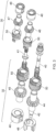
- FIG. 2 shows a cut away perspective view of the interior of a dual stage pump assembly of a fuel supply system of the engine 10, and FIG. 3 shows an exploded perspective view of displacement gear components of the pump assembly of FIG. 2 .
- the pump assembly has in sequence: an outer casing comprising a mounting flange 25; a housing 27 for a smaller primary displacement gear pump 30; a housing 29 for a larger secondary displacement gear pump 32; a centrifugal stage back plate 34 which acts as an end cover for the housing 29 and additionally as a back plate for a centrifugal pump 36; and finally at the end of the casing remote from the mounting flange 25 a low pressure stage housing 38 for the centrifugal pump 36, this housing including the centrifugal pump inlet.
- the centrifugal pump forms the low-pressure stage of the dual stage pump assembly, and the two gear pumps form the high-pressure stage of the assembly.
- the small primary displacement pump 30 is pressurised at all flight conditions, while the large secondary displacement pump 32 is pressurised for high power (above cruise) conditions, and for low speed starting.
- a drive shaft 40 which accepts power from an engine accessory gearbox (not shown) has male spline couplings at each end.
- the drive shaft 40 accommodates for misalignment and connects directly into a driver gear 44 of the secondary gear pump 32, and continues via a linking drive shaft 42 to the impeller and inducer of the centrifugal pump 36.
- a secondary drive shaft 41 transfers power from the secondary pump to the primary pump 30 and also accommodates for misalignment. More particularly, one splined end of the secondary drive shaft is engaged internally with the driven gear 45 of the larger, secondary displacement pump, whilst its opposite splined end is engaged internally with the driver gear 46 of the smaller, primary gear pump, which drives the driven gear 47 of the primary gear pump.
- Each displacement pump gear 44-47 has a respective solid bearing block 48 and a respective pressure-loaded bearing block 50 which are adapted to receive a bearing shaft or journal of the gear.
- FIG. 4 shows a first example embodiment of a gear pump system 100 (more generally referred to a positive displacement pump system).
- the gear pump system 100 includes similar features to the gear pump 32 described above and corresponding features which be labelled appropriately to denote this.
- the gear pump system 100 generally comprises a first gear pump module 132a, a second gear pump module 132b and an electric motor 152 which are disposed within a common housing 129.
- Each of the first and second gear pump modules 132a, 132b comprise first and second gears 144, 145 which are disposed on shafts 147, 149 respectively.
- the ends of each of the shafts 147, 149 are received in openings formed in bearing blocks 148, 150 (which may be solid and pressure-loaded bearing blocks, as described previously) such that the first and second gears 144, 145 are axially disposed (i.e., sandwiched) between the bearing blocks 148, 150.
- the shafts 147, 149 are hollow.
- the electric motor 152 comprises a stator 154 and a rotor 156.
- the stator 154 is cylindrical and the rotor 156 is disposed within the stator 154.
- the electric motor 152 may be any type of electric motor, such as a switched reluctance, permanent magnet or induction type motor.
- a shaft 158 extends through the rotational axis of the rotor 156.
- the shaft 158 is hollow and projects from either side of the rotor 156.
- An intermediate drive shaft extends between the rotor 156 and each of the shafts 147.
- Each intermediate drive shaft has male splined sections 160', 160" either end.
- the male splined section 160' is received in the hollow shaft 158 of the rotor 156 and engages with a female splined section formed therewithin.
- the male splined section 160" is received in the hollow shaft 147 of the first/second gear pump 132a, 132b and engages with a female splined section formed therewithin.
- Each intermediate drive shaft provides rotational engagement between the rotor 156 and the first gear 144 of each of the first and second gear pump modules 132a, 132b.
- a further external coupling 162 may be provided between the shaft 158 of the rotor 156 and each of the shafts 147.
- the coupling 162 is configured to transfer (radial) load and allow for articulation to accommodate misalignment.
- the coupling 162 may be a flexible coupling (e.g., a bellows coupling) that allows for angular misalignment, axial misalignment, and/or eccentricity.
- the rotor 156 is supported by the first and second gear pump modules 132a, 132b and so the motor 152 does not require its own bearings. This simplifies the design and reduces the size and mass.
- the electric motor 152 may be activated to cause rotation of the rotor 156.
- the rotation of the rotor 156 causes rotation of the first gears 144 via the intermediate drive shafts and, in turn, this causes rotation of the second gears 145 as a result of the meshing between the first and second gears 144, 145.
- the first gears 144 thus form drive gears and the second gears 145 thus form driven (or idler) gears.
- the rotation of the first and second gears 144, 145 acts to draw fuel from an inlet 164 formed in the housing 129 which opens into an area between the first and second gears 144, 145.
- the fuel is forced around the outside of the first and second gears 144, 145 towards and out of an outlet 166 which is diametrically opposed to the inlet 164.
- the housing 129 may include internal features (e.g., galleries) which divide a common inlet flow into two separate flow paths which supply the inlets 164 of the first and second gear pump modules 132a, 132b. Similar features may be provided to combine the fuel from the separate outlets 166 into a common outlet flow. Alternatively, the flow may be separated and/or recombined externally to the housing 129.
- the electrical motor 152 is immersed in fuel from the first and second gear pump modules 132a, 132b and/or from a separate supply of fuel (e.g., in a cooling circuit).
- the fuel may be used to cool the electrical motor 152.
- As the electrical motor 152 is immersed in fuel there is no need to provide rotary shaft seals between the electrical motor 152 and the first and second gear pump modules 132a, 132b (i.e., on the shafts 147, 158). Such seals are prone to leaking on conventional pumps and so lead to in-service disruption while they are removed and replaced.
- the use of two gear pump modules allows the pump to be operated at a higher speed for a given inlet pressure. This results in reduced size and mass. Further, by timing the two gear pump modules 132a, 132b, it is possible to dampen the flow ripple introduced into the system. The low speed of an electric motor driven pump will reduce low frequency flow ripple which might interact with the engine dynamics hence being able to tune the magnitude of the flow ripple is a significant benefit.
- the two gear pump modules 132a, 132b may be effectively timed through the configuration of the inlet and outlet pathways (e.g., by having different lengths) so as to provide a phase difference between the respective flow ripples which leads to destructive interference.
- FIG. 5 shows an alternative embodiment of a gear pump system 200.
- the bearing block 250 comprises an extension portion 262 which supports the shafts 247 of the first and second gear pump modules 232a, 232b and the shaft 258 of the rotor 256.
- the extension portion 262 therefore replaces the coupling 152 of the first embodiment.
- the present invention may find use in the context of a fuel supply system for a gas turbine engine, the present invention may be applied in other contexts in aerospace and other industries to pump other liquids (e.g., oil).
- liquids e.g., oil
Landscapes
- Engineering & Computer Science (AREA)
- Mechanical Engineering (AREA)
- General Engineering & Computer Science (AREA)
- Rotary Pumps (AREA)
Abstract
A positive displacement pump system (100) comprises: a first positive displacement pump (132a) comprising a rotatable element (144); a second positive displacement pump (132b) comprising a rotatable element (144); and an electric motor (152) comprising a stator (154) and a rotor (156). The rotor (156) is coupled to the rotatable elements (144) of the first and second positive displacement pumps (132a, 132b) to provide drive thereto. The rotor (156) is supported for rotation by the rotatable elements (144) of the first and second positive displacement pumps (132a, 132b). The rotatable elements (144) of the first positive displacement pump (132a) and the second positive displacement pump (132b) each comprise pump shafts (147) which are coupled to a rotor shaft of the rotor (156).
Description
- The present invention concerns a positive displacement pump system, and particularly, but not exclusively, to a gear pump system for pumping fuel or oil in an aero-engine (e.g., a gas turbine engine).
- A typical fuel pumping unit for an aero-engine comprises a low pressure (LP) pump operable to draw fuel from a fuel tank, and supplying the fuel at boosted pressure to the inlet of a high pressure (HP) pump. The inter-stage flow between LP and HP pumps is typically used to cool engine lubrication oil in a fuel/oil heat exchanger.
- Commonly, the LP pump comprises a centrifugal impeller pump whilst the HP pump comprises a positive displacement pump in the form of a twin pinion gear pump.
- A twin pinion gear pump comprises first and second pinion gears mounted on parallel first and second gear shafts, such that the gears mesh with one another. One of the first and second gear shafts typically extends externally to a housing of the pump to form an input drive shaft. The input drive shaft is connected to an external drive, such as the accessory gearbox of the engine or an electric motor, in order to pump the fuel. A rotating seal is typically required to avoid leakage around the input drive shaft where it passes through the housing.
- It is desired to provide improvements in gear pump systems, and more generally positive displacement pump systems, which aim to simplify their construction, assembly and maintenance, as well as providing enhanced performance.
- According to an aspect there is provided a positive displacement pump system comprising: a first positive displacement pump comprising a rotatable element; a second positive displacement pump comprising a rotatable element; and an electric motor comprising a stator and a rotor, the rotor being coupled to the rotatable elements of the first and second positive displacement pumps to provide drive thereto; the rotor is supported for rotation by the rotatable elements of the first and second positive displacement pumps; wherein the rotatable elements of the first and second positive displacement pumps each comprise pump shafts which are coupled to a rotor shaft of the rotor.
- The electric motor may be supported solely by the rotatable elements of the first and second positive displacement pumps. As a result, the electric motor does not require its own bearings to support the rotor.
- The pump shafts and the rotor shaft may be connected by respective intermediate drive shafts extending therebetween.
- The pump shafts and the rotor shaft may be hollow and the intermediate drive shaft may be received within the pump shafts and the rotor shaft.
- The intermediate drive shaft may be connected with the pump shafts and the rotor shaft by splined connections.
- The pump shafts and the rotor shaft may be connected by an external coupling. The external coupling may be a flexible coupling.
- Each pump shaft may be supported by a respective pair of bearing blocks.
- One of each pair of bearing blocks may further support the rotor shaft.
- Said one of each pair of bearing blocks may comprise an extension portion which supports the rotor shaft.
- The first positive displacement pump, the second positive displacement pump and the electric motor may be disposed within a common housing.
- The electric motor may be at least partially immersed in a pumped liquid. In particular, the rotor of the electric motor may be immersed in the pumped liquid and, optionally, the stator may also be immersed in the pumped liquid. The pumped liquid may provide cooling to the electric motor. As the electric motor is immersed in the pumped liquid, it is not necessary to provide rotary seals between the first and second positive displacement pumps and the electric motor.
- Each of the first and/or second positive displacement pumps may be a gear pump and the rotating element may be a first gear of the gear pump, the gear pump further comprising a second gear which meshes with and is driven by the first gear.
- According to another aspect there is provided a gas turbine engine comprising a positive displacement pump system as described above. The positive displacement pump system may be part of a fuel or oil supply system of the gas turbine engine.
- The skilled person will appreciate that except where mutually exclusive, a feature described in relation to any one of the above aspects may be applied mutatis mutandis to any other aspect. Furthermore except where mutually exclusive any feature described herein may be applied to any aspect and/or combined with any other feature described herein.
- Embodiments will now be described by way of example only, with reference to the Figures, in which:
-
FIG. 1 is a sectional side view of a gas turbine engine; -
FIG. 2 shows a cut away perspective view of the interior of a pump assembly of the gas turbine engine; -
FIG. 3 shows an exploded perspective view of some components of the pump assembly ofFIG. 2 ; -
FIG. 4 is a cross-sectional plan view of a first example embodiment of a gear pump system; and -
FIG. 5 is a cross-sectional plan view of a second example embodiment of a gear pump system. - The following table lists the reference numerals used in the drawings with the features to which they refer:
Ref no. Feature Figure 10 Gas turbine engine 1 11 Principal and rotational axis 1 12 Air intake 1 13 Fan 1 14 Intermediate pressure compressor (IPC) 1 15 High pressure compressor (HPC) 1 16 Combustion equipment 1 17 High pressure turbine (HPT) 1 18 Intermediate pressure turbine (IPT) 1 19 Low pressure turbine (LPT) 1 20 Exhaust nozzle 1 21 Nacelle 1 22 Bypass duct 1 25 Mounting flange 2 27 Housing (for gear pump 30) 2 29 Housing (for gear pump 32) 2 30 Primary displacement gear pump 23 32 Secondary displacement gear pump 23 34 Centrifugal stage back plate 2 36 Centrifugal pump 2 38 Low pressure stage housing 2 40 Drive shaft 2 41 Secondary drive shaft 3 42 Linking drive shaft 3 44 Driver gear 23 45 Driven gear 23 46 Driver gear 23 47 Driven gear 3 48 Solid bearing block 23 50 Pressure-loaded bearing block 23 100 Gear pump system 4 129 Housing 4 132a First gear pump module 4 132b Second gear pump module 4 144 First gear 4 145 Second gear 4 147 Shaft 4 148 Bearing block 4 149 Shaft 4 150 Bearing block 4 152 Electric motor 4 154 Stator 4 156 Rotor 4 158 Shaft 4 160' Male splined section 4 160" Male splined section 4 162 Coupling 4 164 Inlet 4 166 Outlet 4 200 Gear pump system 5 229 Housing 5 232a First gear pump module 5 232b Second gear pump module 5 244 First gear 5 245 Second gear 5 247 Shaft 5 248 Bearing block 5 249 Shaft 5 250 Bearing block 5 252 Electric motor 5 254 Stator 5 256 Rotor 5 258 Shaft 5 260' Male splined section 5 260" Male splined section 5 262 Extension portion 5 264 Inlet 5 266 Outlet 5 - Aspects and embodiments of the present invention will now be discussed with reference to the accompanying figures. Further aspects and embodiments will be apparent to those skilled in the art.
- With reference to
FIG. 1 , a gas turbine engine is generally indicated at 10, having a principal androtational axis 11. Theengine 10 comprises, in axial flow series, anair intake 12, apropulsive fan 13, anintermediate pressure compressor 14, a high-pressure compressor 15,combustion equipment 16, a high-pressure turbine 17, anintermediate pressure turbine 18, a low-pressure turbine 19 and anexhaust nozzle 20. Anacelle 21 generally surrounds theengine 10 and defines both theintake 12 and theexhaust nozzle 20. - The
gas turbine engine 10 works in the conventional manner so that air entering theintake 12 is accelerated by thefan 13 to produce two air flows: a first air flow into theintermediate pressure compressor 14 and a second air flow which passes through abypass duct 22 to provide propulsive thrust. Theintermediate pressure compressor 14 compresses the air flow directed into it before delivering that air to the high-pressure compressor 15 where further compression takes place. - The compressed air exhausted from the high-
pressure compressor 15 is directed into thecombustion equipment 16 where it is mixed with fuel and the mixture combusted. The resultant hot combustion products then expand through, and thereby drive the high, intermediate and low-pressure turbines nozzle 20 to provide additional propulsive thrust. The high 17, intermediate 18 and low 19 pressure turbines drive respectively the high-pressure compressor 15,intermediate pressure compressor 14 andfan 13, each by suitable interconnecting shaft. - Other gas turbine engines to which the present invention may be applied may have alternative configurations. By way of example such engines may have an alternative number of interconnecting shafts (e.g. two) and/or an alternative number of compressors and/or turbines. Further the engine may comprise a gearbox provided in the drive train from a turbine to a compressor and/or fan.
-
FIG. 2 shows a cut away perspective view of the interior of a dual stage pump assembly of a fuel supply system of theengine 10, andFIG. 3 shows an exploded perspective view of displacement gear components of the pump assembly ofFIG. 2 . The pump assembly has in sequence: an outer casing comprising amounting flange 25; ahousing 27 for a smaller primarydisplacement gear pump 30; ahousing 29 for a larger secondarydisplacement gear pump 32; a centrifugalstage back plate 34 which acts as an end cover for thehousing 29 and additionally as a back plate for acentrifugal pump 36; and finally at the end of the casing remote from the mounting flange 25 a lowpressure stage housing 38 for thecentrifugal pump 36, this housing including the centrifugal pump inlet. The centrifugal pump forms the low-pressure stage of the dual stage pump assembly, and the two gear pumps form the high-pressure stage of the assembly. Typically, the smallprimary displacement pump 30 is pressurised at all flight conditions, while the largesecondary displacement pump 32 is pressurised for high power (above cruise) conditions, and for low speed starting. - A
drive shaft 40 which accepts power from an engine accessory gearbox (not shown) has male spline couplings at each end. Thedrive shaft 40 accommodates for misalignment and connects directly into adriver gear 44 of thesecondary gear pump 32, and continues via a linkingdrive shaft 42 to the impeller and inducer of thecentrifugal pump 36. Asecondary drive shaft 41 transfers power from the secondary pump to theprimary pump 30 and also accommodates for misalignment. More particularly, one splined end of the secondary drive shaft is engaged internally with the drivengear 45 of the larger, secondary displacement pump, whilst its opposite splined end is engaged internally with thedriver gear 46 of the smaller, primary gear pump, which drives the drivengear 47 of the primary gear pump. - Each displacement pump gear 44-47 has a respective solid bearing
block 48 and a respective pressure-loadedbearing block 50 which are adapted to receive a bearing shaft or journal of the gear. -
FIG. 4 shows a first example embodiment of a gear pump system 100 (more generally referred to a positive displacement pump system). Thegear pump system 100 includes similar features to thegear pump 32 described above and corresponding features which be labelled appropriately to denote this. - The
gear pump system 100 generally comprises a firstgear pump module 132a, a secondgear pump module 132b and anelectric motor 152 which are disposed within acommon housing 129. Each of the first and secondgear pump modules second gears shafts shafts blocks 148, 150 (which may be solid and pressure-loaded bearing blocks, as described previously) such that the first andsecond gears shafts - The
electric motor 152 comprises astator 154 and arotor 156. Thestator 154 is cylindrical and therotor 156 is disposed within thestator 154. - The
electric motor 152 may be any type of electric motor, such as a switched reluctance, permanent magnet or induction type motor. - A
shaft 158 extends through the rotational axis of therotor 156. Theshaft 158 is hollow and projects from either side of therotor 156. - An intermediate drive shaft extends between the
rotor 156 and each of theshafts 147. Each intermediate drive shaft has malesplined sections 160', 160" either end. The male splined section 160' is received in thehollow shaft 158 of therotor 156 and engages with a female splined section formed therewithin. Similarly, at the opposite end, the malesplined section 160" is received in thehollow shaft 147 of the first/second gear pump rotor 156 and thefirst gear 144 of each of the first and secondgear pump modules external coupling 162 may be provided between theshaft 158 of therotor 156 and each of theshafts 147. Thecoupling 162 is configured to transfer (radial) load and allow for articulation to accommodate misalignment. Thecoupling 162 may be a flexible coupling (e.g., a bellows coupling) that allows for angular misalignment, axial misalignment, and/or eccentricity. - As will be appreciated, the
rotor 156 is supported by the first and secondgear pump modules motor 152 does not require its own bearings. This simplifies the design and reduces the size and mass. - The
electric motor 152 may be activated to cause rotation of therotor 156. The rotation of therotor 156 causes rotation of thefirst gears 144 via the intermediate drive shafts and, in turn, this causes rotation of thesecond gears 145 as a result of the meshing between the first andsecond gears first gears 144 thus form drive gears and thesecond gears 145 thus form driven (or idler) gears. - The rotation of the first and
second gears housing 129 which opens into an area between the first andsecond gears second gears housing 129 may include internal features (e.g., galleries) which divide a common inlet flow into two separate flow paths which supply the inlets 164 of the first and secondgear pump modules housing 129. - The
electrical motor 152 is immersed in fuel from the first and secondgear pump modules electrical motor 152. As theelectrical motor 152 is immersed in fuel, there is no need to provide rotary shaft seals between theelectrical motor 152 and the first and secondgear pump modules shafts 147, 158). Such seals are prone to leaking on conventional pumps and so lead to in-service disruption while they are removed and replaced. - The use of two gear pump modules allows the pump to be operated at a higher speed for a given inlet pressure. This results in reduced size and mass. Further, by timing the two
gear pump modules gear pump modules -
FIG. 5 shows an alternative embodiment of agear pump system 200. In this embodiment, thebearing block 250 comprises anextension portion 262 which supports theshafts 247 of the first and secondgear pump modules shaft 258 of therotor 256. Theextension portion 262 therefore replaces thecoupling 152 of the first embodiment. - Although the embodiments above have been described with reference to external gear pumps, it will be appreciated that it may be applied to other positive displacement pumps. In particular, it may be used with rotary pumps, such as internal gear pumps, screw pumps, peristaltic pumps, vane pumps, lobe pumps, etc., as well as reciprocating pumps (which have a rotating drive component which can support the rotor of the motor), such as diaphragm pumps, piston pumps, plunger pumps, etc. and any combination of such pumps.
- Whilst it is envisaged that the present invention may find use in the context of a fuel supply system for a gas turbine engine, the present invention may be applied in other contexts in aerospace and other industries to pump other liquids (e.g., oil).
- It will be understood that the invention is not limited to the embodiments above-described and various modifications and improvements can be made without departing from the concepts described herein. Except where mutually exclusive, any of the features may be employed separately or in combination with any other features and the invention extends to and includes all combinations and sub-combinations of one or more features described herein.
Claims (15)
- A positive displacement pump system (100) comprising:a first positive displacement pump (132a) comprising a rotatable element (144);a second positive displacement pump (132b) comprising a rotatable element (144); andan electric motor (152) comprising a stator (154) and a rotor (156), the rotor being coupled to the rotatable elements (144) of the first positive displacement pump (132a) and the second positive displacement pump (132b) to provide drive thereto;wherein the rotor (156) is supported for rotation by the rotatable elements (144) of the first positive displacement pump (132a) and the second positive displacement pump (132b); andwherein the rotatable elements (144) of the first positive displacement pump (132a) and the second positive displacement pump (132b) each comprise pump shafts (147) which are coupled to a rotor shaft of the rotor (156).
- The positive displacement pump system (100) of claim 1, wherein the electric motor (152) is supported solely by the rotatable elements (144) of the first positive displacement pump (132a) and the second positive displacement pump (132b).
- The positive displacement pump system (100) of claim 1 or 2, wherein the pump shafts (147) and the rotor shaft are connected by respective intermediate drive shafts extending therebetween.
- The positive displacement pump system (100) of claim 3, wherein the pump shafts (147) and the rotor shaft are hollow and the intermediate drive shaft is received within the pump shafts (147) and the rotor shaft.
- The positive displacement pump system (100) of claim 3 or 4, wherein the intermediate drive shaft is connected with the pump shafts (147) and the rotor shaft by splined connections.
- The positive displacement pump system (100) of any preceding claim, wherein the pump shafts (147) and the rotor shaft are connected by an external coupling (162).
- The positive displacement pump system (100) of claim 6, wherein the external coupling (162) is a flexible coupling.
- The positive displacement pump system (100) of any preceding claim, wherein each pump shaft (147) is supported by a respective pair of bearing blocks.
- The positive displacement pump system (100) of claim 8, wherein one of each pair of bearing blocks further supports the rotor shaft.
- The positive displacement pump system (100) of claim 9, wherein said one of each pair of bearing blocks comprises an extension portion (262) which supports the rotor shaft.
- The positive displacement pump system (100) of any preceding claim, wherein the first positive displacement pump (132a), the second positive displacement pump (132b) and the electric motor (152) are disposed within a common housing.
- The positive displacement pump system (100) of claim 11, wherein the electric motor (152) is at least partially immersed in a pumped liquid.
- The positive displacement pump system (100) of any preceding claim, wherein each of the first positive displacement pump (132a) and/or second positive displacement pump (132b) is a gear pump and the rotating element is a first gear (144, 244) of the gear pump, the gear pump further comprising a second gear (145, 245) which meshes with and is driven by the first gear.
- A gas turbine engine (10) including a positive displacement pump system (100) of any preceding claim.
- The gas turbine engine (10) of claim 14, wherein the positive displacement pump system (100) is part of a fuel or oil supply system.
Applications Claiming Priority (1)
| Application Number | Priority Date | Filing Date | Title |
|---|---|---|---|
| GBGB2319533.2A GB202319533D0 (en) | 2023-12-19 | 2023-12-19 | Positive displacement pump system |
Publications (1)
| Publication Number | Publication Date |
|---|---|
| EP4575229A1 true EP4575229A1 (en) | 2025-06-25 |
Family
ID=89662669
Family Applications (1)
| Application Number | Title | Priority Date | Filing Date |
|---|---|---|---|
| EP24215292.4A Pending EP4575229A1 (en) | 2023-12-19 | 2024-11-26 | Positive displacement pump system |
Country Status (3)
| Country | Link |
|---|---|
| US (1) | US20250250979A1 (en) |
| EP (1) | EP4575229A1 (en) |
| GB (1) | GB202319533D0 (en) |
Citations (4)
| Publication number | Priority date | Publication date | Assignee | Title |
|---|---|---|---|---|
| EP1443210A2 (en) * | 2003-01-31 | 2004-08-04 | Voith Turbo GmbH | Motor-pump unit |
| US20050232784A1 (en) * | 2004-04-19 | 2005-10-20 | Yates Martin K | Pump assembly |
| US20060153705A1 (en) * | 2004-11-10 | 2006-07-13 | Horton W T | Drive shaft for compressor |
| US20160281712A1 (en) * | 2013-03-20 | 2016-09-29 | Magna Powertrain Inc. | Tandem electric pump |
Family Cites Families (2)
| Publication number | Priority date | Publication date | Assignee | Title |
|---|---|---|---|---|
| US11624362B2 (en) * | 2015-08-07 | 2023-04-11 | Magpumps Limited | Device for pumping fluid |
| GB201518619D0 (en) * | 2015-10-21 | 2015-12-02 | Rolls Royce Controls & Data Services Ltd | Gear Pump |
-
2023
- 2023-12-19 GB GBGB2319533.2A patent/GB202319533D0/en not_active Ceased
-
2024
- 2024-11-26 EP EP24215292.4A patent/EP4575229A1/en active Pending
- 2024-12-04 US US18/967,800 patent/US20250250979A1/en active Pending
Patent Citations (4)
| Publication number | Priority date | Publication date | Assignee | Title |
|---|---|---|---|---|
| EP1443210A2 (en) * | 2003-01-31 | 2004-08-04 | Voith Turbo GmbH | Motor-pump unit |
| US20050232784A1 (en) * | 2004-04-19 | 2005-10-20 | Yates Martin K | Pump assembly |
| US20060153705A1 (en) * | 2004-11-10 | 2006-07-13 | Horton W T | Drive shaft for compressor |
| US20160281712A1 (en) * | 2013-03-20 | 2016-09-29 | Magna Powertrain Inc. | Tandem electric pump |
Also Published As
| Publication number | Publication date |
|---|---|
| US20250250979A1 (en) | 2025-08-07 |
| GB202319533D0 (en) | 2024-01-31 |
Similar Documents
| Publication | Publication Date | Title |
|---|---|---|
| RU2406846C2 (en) | Starter/generator module box integration into gear box of gas turbine | |
| RU2424435C2 (en) | Jet turbine engine equipped with built-in electric generator | |
| EP3828402B1 (en) | Gas turbine engine having first and second lubrication systems and associated method | |
| US10138816B2 (en) | Fuel pumping unit | |
| EP2447507B1 (en) | Turbomachine cooling arrangement | |
| US7040082B2 (en) | Assistance and emergency drive for electrically-driven accessories | |
| EP1748170A2 (en) | PTO assembly for a gas turbine engine, gas turbine engine and method of operation of a gas turbine engine | |
| US7418821B2 (en) | Aircraft gas turbine engines | |
| EP3699414B1 (en) | Gas turbine engine with accessory gearbox | |
| EP2859194A1 (en) | Combination of two gas turbines to drive a load | |
| US12378915B2 (en) | Fuel supply circuit of an aircraft engine | |
| EP3159543B1 (en) | Gear pump | |
| US12428131B2 (en) | Module for an aircraft turbine engine | |
| US20250250979A1 (en) | Positive displacement pump system | |
| US12281581B1 (en) | Module for an aircraft turbine engine | |
| JP2008519580A (en) | Electromechanical equipment | |
| US7681397B2 (en) | Heat engine | |
| US6158977A (en) | Air cycle cooling system | |
| CN112412670A (en) | Exhaust gas recirculation blower and internal combustion engine | |
| WO2000073639A1 (en) | Super-charger for i.c. engine | |
| CN121139142A (en) | Aircraft engines and aircraft | |
| GB2350406A (en) | Super-charger for I.C. engine | |
| GB2426290A (en) | Intake and exhaust arrangement in a gas turbine engine |
Legal Events
| Date | Code | Title | Description |
|---|---|---|---|
| PUAI | Public reference made under article 153(3) epc to a published international application that has entered the european phase |
Free format text: ORIGINAL CODE: 0009012 |
|
| STAA | Information on the status of an ep patent application or granted ep patent |
Free format text: STATUS: THE APPLICATION HAS BEEN PUBLISHED |
|
| AK | Designated contracting states |
Kind code of ref document: A1 Designated state(s): AL AT BE BG CH CY CZ DE DK EE ES FI FR GB GR HR HU IE IS IT LI LT LU LV MC ME MK MT NL NO PL PT RO RS SE SI SK SM TR |
|
| STAA | Information on the status of an ep patent application or granted ep patent |
Free format text: STATUS: REQUEST FOR EXAMINATION WAS MADE |
|
| 17P | Request for examination filed |
Effective date: 20251216 |