EP4575162A1 - Door opening and closing apparatus and electrical device - Google Patents
Door opening and closing apparatus and electrical device Download PDFInfo
- Publication number
- EP4575162A1 EP4575162A1 EP23867030.1A EP23867030A EP4575162A1 EP 4575162 A1 EP4575162 A1 EP 4575162A1 EP 23867030 A EP23867030 A EP 23867030A EP 4575162 A1 EP4575162 A1 EP 4575162A1
- Authority
- EP
- European Patent Office
- Prior art keywords
- door
- ejection
- linkage wheel
- suspension
- closing device
- Prior art date
- Legal status (The legal status is an assumption and is not a legal conclusion. Google has not performed a legal analysis and makes no representation as to the accuracy of the status listed.)
- Pending
Links
Images



Classifications
-
- F—MECHANICAL ENGINEERING; LIGHTING; HEATING; WEAPONS; BLASTING
- F25—REFRIGERATION OR COOLING; COMBINED HEATING AND REFRIGERATION SYSTEMS; HEAT PUMP SYSTEMS; MANUFACTURE OR STORAGE OF ICE; LIQUEFACTION SOLIDIFICATION OF GASES
- F25D—REFRIGERATORS; COLD ROOMS; ICE-BOXES; COOLING OR FREEZING APPARATUS NOT OTHERWISE PROVIDED FOR
- F25D23/00—General constructional features
- F25D23/02—Doors; Covers
- F25D23/028—Details
-
- E—FIXED CONSTRUCTIONS
- E05—LOCKS; KEYS; WINDOW OR DOOR FITTINGS; SAFES
- E05F—DEVICES FOR MOVING WINGS INTO OPEN OR CLOSED POSITION; CHECKS FOR WINGS; WING FITTINGS NOT OTHERWISE PROVIDED FOR, CONCERNED WITH THE FUNCTIONING OF THE WING
- E05F15/00—Power-operated mechanisms for wings
- E05F15/60—Power-operated mechanisms for wings using electrical actuators
- E05F15/603—Power-operated mechanisms for wings using electrical actuators using rotary electromotors
- E05F15/611—Power-operated mechanisms for wings using electrical actuators using rotary electromotors for swinging wings
- E05F15/614—Power-operated mechanisms for wings using electrical actuators using rotary electromotors for swinging wings operated by meshing gear wheels, one of which being mounted at the wing pivot axis; operated by a motor acting directly on the wing pivot axis
-
- E—FIXED CONSTRUCTIONS
- E05—LOCKS; KEYS; WINDOW OR DOOR FITTINGS; SAFES
- E05F—DEVICES FOR MOVING WINGS INTO OPEN OR CLOSED POSITION; CHECKS FOR WINGS; WING FITTINGS NOT OTHERWISE PROVIDED FOR, CONCERNED WITH THE FUNCTIONING OF THE WING
- E05F15/00—Power-operated mechanisms for wings
- E05F15/60—Power-operated mechanisms for wings using electrical actuators
- E05F15/603—Power-operated mechanisms for wings using electrical actuators using rotary electromotors
- E05F15/611—Power-operated mechanisms for wings using electrical actuators using rotary electromotors for swinging wings
- E05F15/616—Power-operated mechanisms for wings using electrical actuators using rotary electromotors for swinging wings operated by push-pull mechanisms
-
- E—FIXED CONSTRUCTIONS
- E05—LOCKS; KEYS; WINDOW OR DOOR FITTINGS; SAFES
- E05F—DEVICES FOR MOVING WINGS INTO OPEN OR CLOSED POSITION; CHECKS FOR WINGS; WING FITTINGS NOT OTHERWISE PROVIDED FOR, CONCERNED WITH THE FUNCTIONING OF THE WING
- E05F15/00—Power-operated mechanisms for wings
- E05F15/60—Power-operated mechanisms for wings using electrical actuators
- E05F15/603—Power-operated mechanisms for wings using electrical actuators using rotary electromotors
- E05F15/611—Power-operated mechanisms for wings using electrical actuators using rotary electromotors for swinging wings
- E05F15/63—Power-operated mechanisms for wings using electrical actuators using rotary electromotors for swinging wings operated by swinging arms
-
- E—FIXED CONSTRUCTIONS
- E05—LOCKS; KEYS; WINDOW OR DOOR FITTINGS; SAFES
- E05F—DEVICES FOR MOVING WINGS INTO OPEN OR CLOSED POSITION; CHECKS FOR WINGS; WING FITTINGS NOT OTHERWISE PROVIDED FOR, CONCERNED WITH THE FUNCTIONING OF THE WING
- E05F5/00—Braking devices, e.g. checks; Stops; Buffers
- E05F5/02—Braking devices, e.g. checks; Stops; Buffers specially for preventing the slamming of swinging wings during final closing movement, e.g. jamb stops
- E05F5/027—Braking devices, e.g. checks; Stops; Buffers specially for preventing the slamming of swinging wings during final closing movement, e.g. jamb stops with closing action
-
- E—FIXED CONSTRUCTIONS
- E05—LOCKS; KEYS; WINDOW OR DOOR FITTINGS; SAFES
- E05Y—INDEXING SCHEME ASSOCIATED WITH SUBCLASSES E05D AND E05F, RELATING TO CONSTRUCTION ELEMENTS, ELECTRIC CONTROL, POWER SUPPLY, POWER SIGNAL OR TRANSMISSION, USER INTERFACES, MOUNTING OR COUPLING, DETAILS, ACCESSORIES, AUXILIARY OPERATIONS NOT OTHERWISE PROVIDED FOR, APPLICATION THEREOF
- E05Y2201/00—Constructional elements; Accessories therefor
- E05Y2201/20—Brakes; Disengaging means; Holders; Stops; Valves; Accessories therefor
- E05Y2201/218—Holders
-
- E—FIXED CONSTRUCTIONS
- E05—LOCKS; KEYS; WINDOW OR DOOR FITTINGS; SAFES
- E05Y—INDEXING SCHEME ASSOCIATED WITH SUBCLASSES E05D AND E05F, RELATING TO CONSTRUCTION ELEMENTS, ELECTRIC CONTROL, POWER SUPPLY, POWER SIGNAL OR TRANSMISSION, USER INTERFACES, MOUNTING OR COUPLING, DETAILS, ACCESSORIES, AUXILIARY OPERATIONS NOT OTHERWISE PROVIDED FOR, APPLICATION THEREOF
- E05Y2201/00—Constructional elements; Accessories therefor
- E05Y2201/40—Motors; Magnets; Springs; Weights; Accessories therefor
- E05Y2201/404—Function thereof
- E05Y2201/418—Function thereof for holding
-
- E—FIXED CONSTRUCTIONS
- E05—LOCKS; KEYS; WINDOW OR DOOR FITTINGS; SAFES
- E05Y—INDEXING SCHEME ASSOCIATED WITH SUBCLASSES E05D AND E05F, RELATING TO CONSTRUCTION ELEMENTS, ELECTRIC CONTROL, POWER SUPPLY, POWER SIGNAL OR TRANSMISSION, USER INTERFACES, MOUNTING OR COUPLING, DETAILS, ACCESSORIES, AUXILIARY OPERATIONS NOT OTHERWISE PROVIDED FOR, APPLICATION THEREOF
- E05Y2201/00—Constructional elements; Accessories therefor
- E05Y2201/40—Motors; Magnets; Springs; Weights; Accessories therefor
- E05Y2201/404—Function thereof
- E05Y2201/422—Function thereof for opening
-
- E—FIXED CONSTRUCTIONS
- E05—LOCKS; KEYS; WINDOW OR DOOR FITTINGS; SAFES
- E05Y—INDEXING SCHEME ASSOCIATED WITH SUBCLASSES E05D AND E05F, RELATING TO CONSTRUCTION ELEMENTS, ELECTRIC CONTROL, POWER SUPPLY, POWER SIGNAL OR TRANSMISSION, USER INTERFACES, MOUNTING OR COUPLING, DETAILS, ACCESSORIES, AUXILIARY OPERATIONS NOT OTHERWISE PROVIDED FOR, APPLICATION THEREOF
- E05Y2201/00—Constructional elements; Accessories therefor
- E05Y2201/40—Motors; Magnets; Springs; Weights; Accessories therefor
- E05Y2201/404—Function thereof
- E05Y2201/422—Function thereof for opening
- E05Y2201/426—Function thereof for opening for the initial opening movement
-
- E—FIXED CONSTRUCTIONS
- E05—LOCKS; KEYS; WINDOW OR DOOR FITTINGS; SAFES
- E05Y—INDEXING SCHEME ASSOCIATED WITH SUBCLASSES E05D AND E05F, RELATING TO CONSTRUCTION ELEMENTS, ELECTRIC CONTROL, POWER SUPPLY, POWER SIGNAL OR TRANSMISSION, USER INTERFACES, MOUNTING OR COUPLING, DETAILS, ACCESSORIES, AUXILIARY OPERATIONS NOT OTHERWISE PROVIDED FOR, APPLICATION THEREOF
- E05Y2201/00—Constructional elements; Accessories therefor
- E05Y2201/60—Suspension or transmission members; Accessories therefor
- E05Y2201/622—Suspension or transmission members elements
- E05Y2201/624—Arms
- E05Y2201/626—Levers
-
- E—FIXED CONSTRUCTIONS
- E05—LOCKS; KEYS; WINDOW OR DOOR FITTINGS; SAFES
- E05Y—INDEXING SCHEME ASSOCIATED WITH SUBCLASSES E05D AND E05F, RELATING TO CONSTRUCTION ELEMENTS, ELECTRIC CONTROL, POWER SUPPLY, POWER SIGNAL OR TRANSMISSION, USER INTERFACES, MOUNTING OR COUPLING, DETAILS, ACCESSORIES, AUXILIARY OPERATIONS NOT OTHERWISE PROVIDED FOR, APPLICATION THEREOF
- E05Y2201/00—Constructional elements; Accessories therefor
- E05Y2201/60—Suspension or transmission members; Accessories therefor
- E05Y2201/622—Suspension or transmission members elements
- E05Y2201/638—Cams; Ramps
-
- E—FIXED CONSTRUCTIONS
- E05—LOCKS; KEYS; WINDOW OR DOOR FITTINGS; SAFES
- E05Y—INDEXING SCHEME ASSOCIATED WITH SUBCLASSES E05D AND E05F, RELATING TO CONSTRUCTION ELEMENTS, ELECTRIC CONTROL, POWER SUPPLY, POWER SIGNAL OR TRANSMISSION, USER INTERFACES, MOUNTING OR COUPLING, DETAILS, ACCESSORIES, AUXILIARY OPERATIONS NOT OTHERWISE PROVIDED FOR, APPLICATION THEREOF
- E05Y2201/00—Constructional elements; Accessories therefor
- E05Y2201/60—Suspension or transmission members; Accessories therefor
- E05Y2201/622—Suspension or transmission members elements
- E05Y2201/686—Rods, links
-
- E—FIXED CONSTRUCTIONS
- E05—LOCKS; KEYS; WINDOW OR DOOR FITTINGS; SAFES
- E05Y—INDEXING SCHEME ASSOCIATED WITH SUBCLASSES E05D AND E05F, RELATING TO CONSTRUCTION ELEMENTS, ELECTRIC CONTROL, POWER SUPPLY, POWER SIGNAL OR TRANSMISSION, USER INTERFACES, MOUNTING OR COUPLING, DETAILS, ACCESSORIES, AUXILIARY OPERATIONS NOT OTHERWISE PROVIDED FOR, APPLICATION THEREOF
- E05Y2201/00—Constructional elements; Accessories therefor
- E05Y2201/60—Suspension or transmission members; Accessories therefor
- E05Y2201/622—Suspension or transmission members elements
- E05Y2201/71—Toothed gearing
-
- E—FIXED CONSTRUCTIONS
- E05—LOCKS; KEYS; WINDOW OR DOOR FITTINGS; SAFES
- E05Y—INDEXING SCHEME ASSOCIATED WITH SUBCLASSES E05D AND E05F, RELATING TO CONSTRUCTION ELEMENTS, ELECTRIC CONTROL, POWER SUPPLY, POWER SIGNAL OR TRANSMISSION, USER INTERFACES, MOUNTING OR COUPLING, DETAILS, ACCESSORIES, AUXILIARY OPERATIONS NOT OTHERWISE PROVIDED FOR, APPLICATION THEREOF
- E05Y2201/00—Constructional elements; Accessories therefor
- E05Y2201/60—Suspension or transmission members; Accessories therefor
- E05Y2201/622—Suspension or transmission members elements
- E05Y2201/71—Toothed gearing
- E05Y2201/712—Toothed gearing with incomplete toothing
-
- E—FIXED CONSTRUCTIONS
- E05—LOCKS; KEYS; WINDOW OR DOOR FITTINGS; SAFES
- E05Y—INDEXING SCHEME ASSOCIATED WITH SUBCLASSES E05D AND E05F, RELATING TO CONSTRUCTION ELEMENTS, ELECTRIC CONTROL, POWER SUPPLY, POWER SIGNAL OR TRANSMISSION, USER INTERFACES, MOUNTING OR COUPLING, DETAILS, ACCESSORIES, AUXILIARY OPERATIONS NOT OTHERWISE PROVIDED FOR, APPLICATION THEREOF
- E05Y2900/00—Application of doors, windows, wings or fittings thereof
- E05Y2900/30—Application of doors, windows, wings or fittings thereof for domestic appliances
-
- E—FIXED CONSTRUCTIONS
- E05—LOCKS; KEYS; WINDOW OR DOOR FITTINGS; SAFES
- E05Y—INDEXING SCHEME ASSOCIATED WITH SUBCLASSES E05D AND E05F, RELATING TO CONSTRUCTION ELEMENTS, ELECTRIC CONTROL, POWER SUPPLY, POWER SIGNAL OR TRANSMISSION, USER INTERFACES, MOUNTING OR COUPLING, DETAILS, ACCESSORIES, AUXILIARY OPERATIONS NOT OTHERWISE PROVIDED FOR, APPLICATION THEREOF
- E05Y2900/00—Application of doors, windows, wings or fittings thereof
- E05Y2900/30—Application of doors, windows, wings or fittings thereof for domestic appliances
- E05Y2900/304—Application of doors, windows, wings or fittings thereof for domestic appliances for dishwashers
-
- E—FIXED CONSTRUCTIONS
- E05—LOCKS; KEYS; WINDOW OR DOOR FITTINGS; SAFES
- E05Y—INDEXING SCHEME ASSOCIATED WITH SUBCLASSES E05D AND E05F, RELATING TO CONSTRUCTION ELEMENTS, ELECTRIC CONTROL, POWER SUPPLY, POWER SIGNAL OR TRANSMISSION, USER INTERFACES, MOUNTING OR COUPLING, DETAILS, ACCESSORIES, AUXILIARY OPERATIONS NOT OTHERWISE PROVIDED FOR, APPLICATION THEREOF
- E05Y2900/00—Application of doors, windows, wings or fittings thereof
- E05Y2900/30—Application of doors, windows, wings or fittings thereof for domestic appliances
- E05Y2900/31—Application of doors, windows, wings or fittings thereof for domestic appliances for refrigerators
Definitions
- adsorption structure is usually provided between a box body and a door body thereof or negative pressure is maintained within the box body, to stably fix the door body on the box body.
- a related performance of the electrical apparatus is improved in this way, a difficulty of opening a door is also increased to a certain extent. Since a larger force is usually required to open the door body, it is inconvenient to use.
- a door opening and closing device can be provided to implement operations of opening and closing a door to reduce a difficulty of operations.
- the door opening and closing device in order to avoid interferences of operations, after the door body reaches a preset opening, the door opening and closing device will stop outputting a driving force. Under an influence of safety measures of the door body or influences of factors such as ground unevenness and the like, the door body will be rotated toward a direction enclosing the box body, and thus cannot maintain in a door open state, to cause an inconvenience in use and even create certain safety risks.
- a support socket 908 may be further disposed below the boss portion 909 to limit and support the above springs, to ensure a stability of ejecting and abutting position of the springs and avoid shaking.
- the door ejection surface 322 may be disposed at a side of the limit recess 320 and opposite to the transition surface 328. During the door ejection surface 322 is rotated with the linkage wheel 300, the door ejection surface 322 abuts against and holds the door ejection member 520, to make the door ejection member 520 move in a direction approaching to the door body 13, and the door ejection member 520 gradually extends out of the door body 13. As the linkage wheel 300 is rotated, the door ejection member 520 extends more and more out of the box body 12, to gradually eject the door body 13 open.
- an angle by which the door member 520 can open the door body 13 is related to a distance between the door ejection surface 322 and the rotation center 310 of the linkage wheel 300.
- a point on the door ejection surface 322 which is farthest from the rotation center 310 of the linkage wheel 300 is defined as the connection point 326. If the distance between the connection point 326 and the rotation center 310 of the linkage wheel 300 is farther, an extending length of the door ejection member 520 is longer, and the angle by which the door body 13 to be opened is larger.
- the door ejection member 520 can eject the door body 13 open by an angle of 3 degrees to 5 degrees. Specifically, the angle can be flexibly set according to an angle required to break through a door-opening resistance force of the door body 13.
- the peripheral surface of the linkage wheel 300 further comprises an avoidance surface 324.
- the avoidance surface 324 is connected to the door ejection surface 322. After the door ejection member is disengaged from abutting and holding with the door ejection surface 322, the elastic reset member 510 can follow the avoidance surface 324 and be reset.
- the door ejection surface 322 In a direction of forward rotation of the linkage wheel 300, the door ejection surface 322 is disposed in front of the avoidance surface 324, that is, in a process of rotation of the linkage wheel 300, the door ejection surface 322 first contacts the door ejection member 520, to eject and abut against the door ejection member 520 to move in a direction approaching to the door body 13. After the door ejection member 520 is disengaged from ejecting and abutting with the door ejection surface 322, the door ejection member 520 can contact the avoidance surface 324, to enable the door ejection member 520 to move in a direction away from the door body 13. Thus, the door ejection member 520 after ejecting the door body 13 open, can be retracted onto the box body 12 to facilitate subsequent closing of the door.
- a main purpose of providing the avoidance surface 324 is to provide the door ejection member 520 with a space to be retracted onto the box body 12 after the door ejection member 520 ejects the door body 13 open.
- the door ejection member 520 can be retracted onto the box body 12 after the door ejection member 520 ejects the door body 13 open, to avoid the door body 13 from being unable to be retracted.
- An elastic member 510 may be disposed on the base 900 and the door ejection member 520. The door ejection member 520 can be retracted onto the box body 12 through a restoring force of the elastic member 510.
- the door ejection member 520 under an action of the restoring force of the elastic member 510, moves in the direction away from the door body 13, to enable the entire door ejection member 520 to be retracted onto the box body 12, to facilitate a closing of the door body 13.
- the elastic member 510 may be a spring or a torsion spring, either one of which may be selected.
- the elastic member 510 is a spring
- the spring is gradually stretched during the process of the door ejection surface 322 ejecting and abutting against the door ejection member 520.
- the spring reaches a maximum stretched amount when the connection point 326 contacts the door ejection member 520.
- the door ejection member 520 is disengaged from abutting and holding with the door ejection surface 322.
- the avoidance surface 324 provides a space for the door ejection member 520 to be retracted onto the box body 12.
- the door ejection member 520 under an action of the restoring force of the spring, moves in the direction away from the door body 13, to enable the entire door ejection member 520 to be retracted onto the box body 12, to facilitate a closing of the door body 13.
- the spring is a torsion spring
- a middle portion of the torsion spring and a first end of the torsion spring are disposed on the base 900, and a second end of the torsion spring is connected to the door ejection member 520.
- the middle portion of is connected to the first end and the second end respectively.
- the elastic member 510 is a torsion spring and when the door ejection member is ejected and abutted against by the door ejection surface 322 to move in a direction approaching to the door body 13, the torsion spring is twisted. After the door ejection member 520 is disengaged from abutting and holding with the door ejection surface 322, the door ejection member 520, under the action of the restoring force of the torsion spring, can follow the avoidance surface 324 to move in the direction away from the door body 13, to enable the door ejection member 520 to be reset to avoid an interference of the door ejection member 520 and the door body 13, and to facilitate a door closing.
- the door ejection surface 322 and the avoidance surface 324 are connected at the connection point 326.
- a distance between the connection point 326 and the rotation center 310 of the linkage wheel 300 is greater than a distance from any point on the avoidance surface 324 and the surface ejection surface to the rotation center 310 of the linkage wheel 300.
- the door ejection surface 322 and the avoidance surface 324 are connected to each other.
- a point where the door ejection surface 322 and the avoidance surface 324 are connected can be defined as the connection point 326.
- the connection point 326 is a point on the door ejection surface 312 and the avoidance surface 324 that is farthest from the rotation center 310 of the linkage wheel 300. In a condition that the connection point 326 ejects and abuts against the door ejection member 520, the door ejection member 520 ejects the door body 13 to open by a maximum angle.
- the avoidance surface 314 When the avoidance surface 324 is rotated at the door ejection member 520, the avoidance surface 314 provides the door ejection member 520 with a space for moving away from the door body 13, to enable the door ejection member 520 to be retracted onto the box body 12, to be convenient for subsequent closing of the door.
- the door body 13 is gradually opened. It is not that the door body 13 is opened by the door ejection member 520 only at a time when the connection point 326 is in contact with the door ejection member 520.
- the door ejection member 520 ejects the door body 13 open. It is only when the connection point 326 ejects and abuts against the door ejection member 520, the door body 13 in a door ejection stage reaches the maximum anlge.
- a speed of ejecting door of the door ejection member 520 is related to a rotation speed of the linkage wheel 300 which is driven by the driving structure. The faster the linkage wheel 300 is rotated, the faster the door ejection member 520 ejects the door body 13 open. If the rotation speed of the linkage wheel 300 is slower, the speed at which the door ejection member 520 ejects the door body 13 open will be slower.
- the avoidance surface 324 and the door ejection surface 322 may be cambered surfaces or inclined planes.
- an end of the door rotation mechanism 400 is connected to the linkage wheel 300, and another end of the door rotation mechanism 400 is connected to the door body 13.
- the door ejection member 520 and the door rotation mechanism 400 can be driven by a same driving structure and linkage wheel 300 to realize functions of ejecting the door and opening the door. Specifically, the door ejection member 520 first ejects the door body 13 open by a smaller angle, and the door rotation mechanism 400 then further opens the door body 13.
- the extending direction of the mounting groove 912 may be from the linkage wheel 300 to the door body 13.
- the mounting groove 912 may be perpendicular to the door body 13 when the door body 13 is closed.
- the door opening and closing device 11 is provided according to some embodiments of the invention.
- the door body 13 is usually pressed onto the box body 12 with a relatively large pressure, or the door body 13 is adsorbed onto the box body 12 through an adsorption structure.
- a door ejection surface 322 is disposed on the linkage wheel 300.
- the door ejection surface 322 can push the door ejection member to move relative to the box body 12, to eject the door body 13 open.
- the door ejection surface 322 disposed on the linkage wheel 300 directly acts on the door ejection member 520 to directly eject the door body 13 open. That is, the linkage wheel 300 can be driven by a driving structure to rotate, to make the door ejection member 520 eject the door body 13 open.
Landscapes
- Engineering & Computer Science (AREA)
- Chemical & Material Sciences (AREA)
- Combustion & Propulsion (AREA)
- Physics & Mathematics (AREA)
- Mechanical Engineering (AREA)
- Thermal Sciences (AREA)
- General Engineering & Computer Science (AREA)
- Power-Operated Mechanisms For Wings (AREA)
Abstract
Description
- This application claims priority to the
Chinese patent application No. 202211145453.4, filed on September 20, 2022 - The invention belongs to the field of electrical apparatus, and in particular to a door opening and closing device and an electrical apparatus.
- With the improvement of living standards, electrical apparatuses such as refrigerators, dishwashers and disinfection cabinets have become widely used in lives of people. In order to maintain a sealing performance of the above-mentioned electrical apparatuses, an adsorption structure is usually provided between a box body and a door body thereof or negative pressure is maintained within the box body, to stably fix the door body on the box body. Although a related performance of the electrical apparatus is improved in this way, a difficulty of opening a door is also increased to a certain extent. Since a larger force is usually required to open the door body, it is inconvenient to use. To this end, a door opening and closing device can be provided to implement operations of opening and closing a door to reduce a difficulty of operations.
- In the related art, in order to avoid interferences of operations, after the door body reaches a preset opening, the door opening and closing device will stop outputting a driving force. Under an influence of safety measures of the door body or influences of factors such as ground unevenness and the like, the door body will be rotated toward a direction enclosing the box body, and thus cannot maintain in a door open state, to cause an inconvenience in use and even create certain safety risks.
- A door opening and closing device and an electrical apparatus are provided according to one or more embodiments of the invention, aiming to at least to some extent solve a technical problem that the door opening and closing device of the electrical apparatus after being shut down cannot maintain an open door state. To this end, According to an aspect of the invention, a door opening and closing device is provided. The door opening and closing device may comprise: a driving mechanism, a door rotation mechanism, a door ejection mechanism, and a suspension mechanism;
- the driving mechanism comprises a linkage wheel. The linkage wheel is rotatably disposed on a base. A limit recess is disposed on a peripheral surface of the linkage wheel. The limit recess has a door ejection surface along a direction of peripheral surface of the linkage wheel;
- the door rotation mechanism is connected to the door body;
- the door ejection mechanism comprises a door ejection member which is movably disposed on the base;
- the suspension mechanism is movably disposed on the base;
- in a condition that the door body is closed, an end of the door ejection member is located in the limit recess, and the suspension mechanism is abutted against and held on the peripheral surface of the linkage wheel.
- In a condition that the linkage wheel is rotated, the linkage wheel pushes, through the door ejection surface, the door ejection member to move relative to the base to push the door body, and then drives the door rotation mechanism to continue to rotate the door body. An end of the suspension mechanism slides along the peripheral surface of the linkage wheel, and thus when the suspension mechanism slides into the limit recess, the suspension mechanism is abutted against and held in the limit recess to provide a acting force to brake the rotation of the linkage wheel.
- According to another aspect of the invention, an electrical apparatus is provided, comprising: a box body, a door body and a door opening and closing device. The door body is rotatably connected to the box body, and the door opening and closing device is connected to the box body and connected to the door body, to open or close the door body and achieve a suspension of the door body when rotating to a preset position.
- In order to more clearly illustrate the technical solutions in the embodiments of the invention, the following briefly introduces the accompanying drawings required for describing the embodiments. Obviously, the accompanying drawings in the following description only illustrate some embodiments of the invention, and for those skilled in the art, other accompanying drawings can also be obtained based on these accompanying drawings without creative efforts.
-
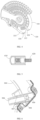
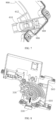
FIG. 1 shows a schematic structural diagram of a door opened and suspended state of a door opening and closing device according to some embodiments of the invention; -
FIG. 2 is a schematic structural diagram showing a door closed state of the door opening and closing device inFIG. 1 ; -
FIG. 3 shows a schematic structural diagram of a suspension mechanism of the door opening and closing device inFIG. 1 ; -
FIG. 4 shows a schematic structural diagram of a linkage wheel of the door opening and closing device inFIG. 1 ; -
FIG. 5 shows a schematic structural diagram of a suspension member and an ejection-push member of the door opening and closing device inFIG. 1 ; -
FIG. 6 shows a schematic structural diagram of a suspension limit slide slot of the door opening and closing device inFIG. 1 ; -
FIG. 7 is a schematic structural diagram showing an assembly of the suspension member and the suspension limit slide slot of the door opening and closing device inFIG. 1 ; -
FIG. 8 is a schematic structural diagram showing an initial state of the door opening and closing device inFIG. 1 ; -
FIG. 9 is a schematic structural diagram showing a door ejection state of the door opening and closing device inFIG. 1 ; -
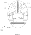
FIG. 10 is a schematic structural diagram showing a suspended state of the door opening and closing device inFIG. 1 ; and -
FIG. 11 shows a schematic structural diagram of the door ejection mechanism of the door opening and closing device inFIG. 10 . - In the accompanying drawings, corresponding relationships between reference signs and component names are as follows:
- 12, box body; 13, door body;
- 200, driving mechanism;
- 300, linkage wheel; 310, rotation center; 320, limit recess; 322, door ejection surface; 324, avoidance surface; 326, connection point; 328, transition surface; 329, fix groove; 329a, first abutting-contacting surface; 329b, second abutting-contacting surface;
- 400, door rotation mechanism; 410, front connecting rod; 420, rear connecting rod; 431, first connection point; 432, second connection point; 433, third connection point;
- 500, door ejection mechanism; 510, elastic member; 520, door ejection member;
- 600, suspension mechanism; 610, suspension member; 611, ejected-abutting portion; 612, push-ejection limit slot; 620, ejection-push member;
- 900, base; 906, suspension limit slide slot; 907, limit boss; 908, support socket; 909, boss portion; 912, mounting groove.
- The technical solutions in the embodiments of the invention will be clearly and completely described below with reference to the accompanying drawings in the embodiments of the invention. Obviously, the described embodiments are only some embodiments, rather than all embodiments of the invention. Based on the embodiments in the invention, all other embodiments obtained by those skilled in the art without creative efforts fall within the protection scope sought by the invention.
- Furthermore, the invention may repeat reference numerals and/or reference letters in different examples. Such repetition is for the purpose of simplicity and clarity and does not in itself indicate a relationship between the various embodiments and/or settings discussed. Furthermore, the invention provides examples of various specific processes and materials, but those skilled in the art may recognize the application of other processes and/or the use of other materials.
- Embodiments of the invention are described below with reference to the accompanying drawings and embodiments.
- As shown in
FIGs. 1 and2 , a door opening and closing device is provided according to an embodiment of the invention. The door opening and closing device is mounted to abox body 12 of an electrical apparatus and is connected to adoor body 13 of the electrical apparatus. The door opening and closing device drives thedoor body 13 to deflect relative to thebox body 12, to close and open thebox body 12, and thus a convenience of operation is improved. The door opening and closing device can also maintain thedoor body 13 at a position with a preset opening after thedoor body 13 reaches the preset opening, to facilitate taking or storing items in thebox body 12. Therefore a comfortability of use is improved and a safety risk of collision caused by the door body deflecting and closing can be avoided. - The door opening and closing device according to an embodiment of the invention can be mainly used on an electrical apparatus to automatically open or close the
door body 13. The door opening and closing device, after receiving a door opening signal, can automatically open thedoor body 13. The door opening signal may be triggered by a user or by the electrical apparatus itself. Likewise, the door opening and closing device, after receiving a door closing signal, can automatically close thedoor body 13. Optionally, the door opening signal may be triggered by a user or by the electrical apparatus itself. - In an embodiment of the invention, the door opening and closing device may comprise: a
door rotation mechanism 400 and adriving mechanism 200. The driving mechanism comprises alinkage wheel 300. Thelinkage wheel 300, as a transmission component for a driving force, is rotatably disposed on the base 900 or thebox body 12, and is connected to an upstream driving device to obtain the driving force and transmit the driving force by rotation. Thelinkage wheel 300 is also connected to thedoor rotation mechanism 400, and thedoor rotation mechanism 400 is connected to thedoor body 13, and thus thedoor rotation mechanism 400 can be driven to act by a rotation of thelinkage wheel 300, to make thedoor body 13 to rotate to implement operations of door opening and closing. In an embodiment of the invention, by providing adoor ejection mechanism 500, adoor rotation mechanism 400 and alinkage wheel 300, thedoor body 13 can be rotated to realize automatic door opening and closing, to reduce a difficulty of manual operation of door opening. Therefore, a convenience and comfortability of operations of door opening and closing can be improved. - When the
door body 13 is rotated to a position with a preset opening, thelinkage wheel 300 will no longer drive thedoor rotation mechanism 400 to act, and a driving force will be stopped from applying to thelinkage wheel 300 to keep thedoor body 13 at current position, that is, a driving relationship between thedoor body 13 and the upstream driving device is broken off, to avoid an interference with manual operation of thedoor body 13, and thus to facilitate a manual operation of thedoor body 13. However, a center of gravity of the door body is caused to be shifted due to items stored on thedoor body 13 of an electrical apparatus such as a refrigerator, or a tilted placement of the refrigerator, which can result in an autonomous deflection of thedoor body 13, so that thedoor body 13 cannot maintain an opening. Thus, it is inconvenient to use and even causes a safety risk of collision to an operator. - As shown in
FIGs. 2 and 3 , in order to solve a problem that thedoor body 13 cannot maintain an opening when the door opening and closing device is shut down, alimit recess 320 may be formed on thelinkage wheel 300, and asuspension mechanism 600 may be disposed on thebase 900. When thelimit recess 320 of thelinkage wheel 300 is rotated to be opposite to thesuspension mechanism 600, thesuspension mechanism 600 moves relative to thebase 900 and then ejects and abuts against thelimit recess 320, to lock thelinkage wheel 300 on thebase 900, to prevent thedoor rotation mechanism 400 from rotating thedoor body 13, to achieve a suspension of thedoor body 13 and maintain a position with preset opening. - That is to say, the
limit recess 320 is rotated with thelinkage wheel 300. Thesuspension mechanism 600 can move relative to thebase 900, and can change a movement state of thesuspension mechanism 600 in response to a position change of rotation of thelinkage wheel 300. Thus, when thelimit recess 320 is rotated to a position where thelimit recess 320 matches with and is opposite to thesuspension device 600, thesuspension device 600 can eject and abut against, and clamp thelimit recess 320, to lock thelinkage wheel 300 and limit a rotation of thelinkage wheel 300, and thus thedoor rotation mechanism 400 can be braked to prevent thedoor body 13 from deflecting, to keep thedoor body 13 to be suspended at a preset position. - It is worth mentioning that a state of ejecting and abutting against for locking of the
suspension mechanism 600 and thelimit recess 320 is a reversible state. When an external driving force applied to thelinkage wheel 300 is greater than a braking force between thesuspension mechanism 600 and thelimit recess 320, thelinkage wheel 300 breaks through an action of ejecting and abutting against for limiting, thelinkage wheel 300 goes on to be rotated to be released from a braking state, driving thedoor rotation mechanism 400 to rotate thedoor body 13 to be closed, or further expanding an opening of thedoor body 13. - As shown in
FIGs. 3 and5 , thesuspension mechanism 600 may comprise asuspension member 610 and an ejection-push member 620. Thesuspension member 610 is movably disposed on thebase 900, and continuously ejects and abuts against thelinkage wheel 300, and can match with, eject and abut against, and clamp thelimit recess 320, and thus when thelinkage wheel 300 makes thelimit recess 320 in a state opposite to thesuspension member 610, thesuspension member 610 can move toward thelinkage wheel 300 and eject and abut against thelimit recess 320, to lock thelinkage wheel 300 on the base 900 to achieve a braking of thelinkage wheel 300. The ejection-push member 620, as a driving element of thesuspension member 610, continuously provides a pushing and ejecting force to the suspension member, to push and eject thesuspension member 610 toward thelinkage wheel 300, to be capable of pushing and ejecting thesuspension member 610 and thelimit recess 320 to eject and abut against thelinkage wheel 300 for braking. - It should be noted that, the
suspension member 610, under an action of continuous pushing and ejecting force, always maintains a state of abutting against thelinkage wheel 300. During a rotation of thelinkage wheel 300, thesuspension member 610 slides on thelinkage wheel 300. Only in a condition that thelinkage wheel 300 is rotated to a state in which thelimit recess 320 is opposite to thesuspension mechanism 600, thesuspension member 610 moves, and ejects and abuts into thelimit recess 320 under the action of the pushing and ejecting force, to brake thelinkage wheel 300. The continuous pushing and ejecting force enables thesuspension member 610 to track a position of rotating of thelinkage wheel 300 and respond to a in-position sate of thelimit recess 320 in a timely manner. That is, after thelimit recess 320 and thesuspension mechanism 600 are aligned, thesuspension member 610 immediately ejects and abuts against and clamps thelimit recess 320. An ejected-abuttingportion 611 may be disposed on thesuspension member 610 for contacting, ejecting and abutting against thelimit recess 320, and may specifically be ejected and abutted into an interior of thelimit recess 320 to implement contacting, ejecting and abutting for braking. - As shown in
FIG. 5 , in some embodiments, thelimit recess 320 may be configured as a groove located on a peripheral surface of thelinkage wheel 300. CooperativelyAccordingly, the ejected-abuttingportion 611 of thesuspension member 610 may be configured as a protruding portion that matches with a groove shape of the groove and ensures that the ejected-abuttingportion 611 can be snapped and embedded into the groove and disengaged from the groove, to facilitate a smooth clamping for braking of the ejected-abuttingportion 611 and a releasing from braking of the ejected-abuttingportion 611. - It is worth noting that a notch of the groove may be provided with a
jointing surface 328 for smoothly jointing to a peripheral surface of thelinkage wheel 300, to facilitate the ejected-abuttingportion 611 to slide smoothly into the groove relative to the peripheral surface of thelinkage wheel 300 and be smoothly disengaged from the groove, and thus the braking and a releasing from braking can be both achieved smoothly and stably. - In some embodiments, a groove shape of the groove may be configured to be C-shaped or V-shaped, and accordingly, the ejected-abutting
portion 611 may also be configured to be an embeddable arc-shaped or spire-shaped structure. - In order to facilitate the ejected-abutting
portion 611 to be smoothly disengaged from the groove, a certain gap may be left between the ejected-abuttingportion 611 and the groove, that is, when the ejected-abuttingportion 611 is snapped and embedded in the groove, a portion of the ejected-abuttingportion 611 is ejected and abutted against an inner wall of the groove 320a, and a gap is formed between another portion and a groove wall of the groove. Therefore, under a premise of ensuring a clamping, the ejected-abuttingportion 611, when subjected to a force slightly greater than the pushing and ejecting force, can also be smoothly disengaged. - As shown in
FIGs. 3 and7 , in some embodiments, it is considered that a stability of the pushing and ejecting force and a stability of acting effect of the pushing and ejecting force have a positive effect on a braking performance of the ejected-abuttingportion 611. A push-ejection limit slot 612 may be formed on thesuspension member 610, and the ejection-push member 620 may be disposed in the push-ejection limit slot 612, to maintain a relatively stable connection state between the ejection-push member 620 and thesuspension member 610. Thus an amplitude of relative swing between the ejection-push member 620 and thesuspension member 610 can be reduced to a certain extent, to maintain stabilities of a direction of subjected force, a movement direction of the ejected-abuttingportion 611, and a contact area between the ejected-abuttingportion 611 and thelimit recess 320, to ensure a braking effect. The ejection-push member 620 may also be directly connected to the ejecting-pushingportion 611 to concentrate an action point of the pushing and ejecting force on the ejecting-pushingportion 611, to reduce a risk of directional deviation of the pushing and ejecting force and an unstable ejecting-abutting effect due to changes in postures of thesuspension member 610 itself. - It is worth noting that specifications of sizes of the push-
ejection limit slot 612 and the ejection-push member 620 may be designed to match with one another. The width of the push-ejection limit slot 612 may be slightly larger than a width of the ejection-push member 620, to reduce a space for relative swing to maintain a stability of direction of the pushing and ejecting force. - In some embodiments, a push-
ejection limit slot 612 may be configured as a blind hole along a direction of the pushing and ejecting force and capable of accommodating the ejection-push member 620. A bottom of the push-ejection limit slot 612 is disposed on the ejecting-pushingportion 611 to form a limit along a peripheral direction for the ejection-push member 620, to limit a swing amplitude in the peripheral direction, reduce a risk of thesuspension member 610 bouncing up under force, and ensure a stability of position and posture of ejection. - In some embodiments, an ejected-abutting
portion 611 is disposed at an end of thesuspension member 610 for contacting, ejecting and abutting against thelimit recess 320. A connecting portion may also be disposed at another end of thesuspension member 610 for connecting the ejection-push member 620. Thus, a molding and processing of the suspension member can be facilitated and a flow of processing can be simplified. - In some embodiments, the ejection-
push member 610 may be configured as an elastic member, and thus a continuous and successive pushing and ejecting force is applied through an elastic deformation of the elastic member, to ensure that thesuspension member 610 responds to position changes of rotation of thelinkage wheel 300 with a simple structure and high time efficiency, and can be quickly ejected and abutted into thelimit recess 320 when thelimit recess 320 is in place. At the same time, a stability of the elastic deformation of the elastic member enables the pushing and ejecting force applied to thesuspension member 610 to maintain a stable state. On the one hand, a stability of a suspended state can be maintained, and on the other hand, thelinkage wheel 300 can also be enabled to be rotated to release a braking state under an action of a relatively stable and controllable driving force, to achieve a stability, a reliability of a suspension function and a performance for smooth implementation of the suspension function of the door opening and closing device. - It is considered that a deformation of the elastic member can be divided into a compressed deformation and a stretched deformation. The elastic member should be assembled in a way which can maintain a relatively stable and linear deformation state .
- When the elastic member in a compressed state provides an elastic pushing and ejecting force, the
suspension member 610 may be disposed between the elastic member and a peripheral surface of thelinkage wheel 300. The elastic member is compressed and disposed between the base 900 and thesuspension member 610, and a reset direction of deformation is kept consistent with a direction of the pushing and ejecting force, to convert an elastic pushing force of the elastic member into a stable elastic pushing and ejecting force to output. - When the elastic member in a stretched state provides an elastic pushing and ejecting force, the elastic member can be stretched and disposed between the base 900 and the
suspension member 610, and the reset direction of deformation of is kept consistent with a direction of the pushing and ejecting force, to convert an elastic pulling force of the elastic member into a stable elastic pushing and ejecting force to output. - In some embodiments, the elastic member is a spring and may specifically be configured as a compression spring or a tension spring, to provide a stable pushing and ejecting force through a compressed deformation or a stretched deformation. The compression spring may specifically be compressed between the
suspension member 610 and thebase 900, or the tension spring may be stretched and connected between thesuspension member 610 and thebase 900. - As shown in
FIGs. 6 and7 , a first end of the spring can be ejected and abutted against the ejecting-pushingportion 611. Aboss portion 909 with a height substantially equal to that of the spring is disposed on thebase 900. A second end of the spring can be ejected and abutted against theboss portion 909 to keep the spring in a straight posture in an axial direction thereof, to form a stable and reliable pushing and ejecting force. - The first end of the tension spring may be fixed on a body of the ejection-
push member 610, or directly fixed on the ejecting-pushingportion 611, and the second end of the tension spring may be fixed on theboss portion 909 that is disposed on thebase 900. The tension spring should be kept flush with a plate surface of thebase 900 and in a straight posture as much as possible to form a stable and reliable push-out force. - In some embodiments, a
support socket 908 may be further disposed below theboss portion 909 to limit and support the above springs, to ensure a stability of ejecting and abutting position of the springs and avoid shaking. - In some embodiments, an elastic member such as a torsion spring, a leaf spring, etc., may also be adopted, as long as a direction of elastic force is roughly consistent with a moving direction of the
suspension member 610, which will not be repeated here. - In some embodiments, in order to maintain a stability of moving direction of the
suspension member 610 and limit an excessive swing and vibration of thesuspension member 610, a suspensionlimit slide slot 906 may be disposed on thebase 900, and thesuspension member 610 may be disposed in the suspensionlimit slide slot 906. The stability of the moving direction of thesuspension member 610 is maintained by a guiding and restraining effect of side walls of the suspensionlimit slide slot 906, to ensure a reliability of braking performance. - As shown in
FIG. 6 , in some embodiments, the suspensionlimit slide slot 906 may be configured as a gap between twoopposite limit bosses 907. Thelimit bosses 907 may have a certain length in the moving direction of thesuspension member 610, as long as a limit within a sliding stroke can be achieved. An upper limit structure may also be connected to a top of the twolimit bosses 907 to limit it from disengaging from the base 900 to a certain extent. A corresponding upper limit structure may also be disposed on an upper cover of thebase 900. The upper limit structure is opposite to the suspensionlimit slide slot 906 to achieve a purpose of upper limit. Thus, thesuspension member 610 can always move in a stable direction to ensure a reliability of braking performance. - In some embodiments, in order to maintain the stability of the moving direction of the
suspension member 610 and limit an unstable swinging of thesuspension member 610, thesuspension member 610 may be configured as rod-shaped, and the ejected-abuttingportion 611 is disposed at an end of thesuspension member 610 which is close to thelinkage wheel 300, that is, thesuspension member 610 may be configured as a structural member with long strip shape having a certain length to cooperate with the suspensionlimit slide slot 906 to implement a stable sliding. A length characteristic of the long strip structural member and a radial limit effect of thesuspension limit recess 906 on the long strip structural member can be utilized to reduce a swing amplitude to a certain extent. Generally speaking, the longer a length in a direction of the pushing and ejecting force of the suspensionlimit slide slot 906 and a length of the rod-shapedsuspension member 610 are, the better a performance of limiting the swing amplitude is, and the more stable the moving direction of thesuspension member 610 is. - As shown in
FIG. 1 andFIG. 2 , in some embodiments, thedoor rotation mechanism 400 may comprise a front connectingrod 410 and arear connecting rod 420 which are hinged connections at ends. Another end of the front connectingrod 410 is rotatably connected to thedoor body 13 at afirst connection point 431. The front connectingrod 410 is disposed between a bottom surface of thelinkage wheel 300 and thebase 900. Therear connecting rod 420 is deflectably disposed in afix groove 329 which is formed on a top surface of thelinkage wheel 300. Another end of the rear connecting rod may be in a coaxial-rotation way at therotation center 310 of thelinkage gear 300 to be connected at thebase 900, that is, therear connecting rod 420 can be rotated with thelinkage wheel 300, and thus the front connectingrod 410 is pushed and pulled under pushes of a first abutting-holdingsurface 329a and a second abutting-holdingsurface 329b oppositely formed on groove walls of thefix groove 329 to rotate thedoor body 13, to implement operations of door opening and closing. - It is worth mentioning that the front connecting
rod 410 and therear connecting rod 420 are respectively disposed on two sides of thelinkage wheel 300, that is, reserved spaces of thick thelinkage wheel 300 which is rotatably supported on the base 900 can be utilized without occupying an upper space of thelinkage wheel 300, to reduce a space requirement of thedoor rotation mechanism 400 in a thickness direction to a certain extent. Therear connecting rod 420 is sunken and disposed in thefix groove 329, to make an overall assembly height of thedoor rotation mechanism 400 and thelinkage wheel 300 not be excessively higher than a height of thelinkage wheel 300, and even be the same. Overall, a thickness of the door opening and closing device can be reduced by disposing thefront connecting rod 410 and therear connecting rod 420 at the sides respectively and using thefix groove 329. - In some embodiments, the
front connecting rod 410 and therear connecting rod 420 can also be disposed in a lower space of thelinkage wheel 300 and is located above thebase 900. Thefix groove 329 is also disposed on a bottom surface of thelinkage wheel 300, to reduce an overall thickness of the door opening and closing device as a whole. - In some embodiments, the
door body 13 and thebox body 12 are rotatably connected at afirst connection point 431. The front connectingrod 410 and thedoor body 13 are connected at asecond connection point 432. Therear connecting rod 420 and the front connectingrod 410 are rotatably connected at athird connection point 433. Thelinkage wheel 300 has arotation center 310. Thesecond connection point 432 and thethird connection point 433 are respectively located on two sides of a line connecting thefirst connection point 431 and therotation center 310, and thus points of force application of two connecting rods are respectively located on two sides of the above-mentioned line. When deformation due to force occurs on the two connecting rods, deformation directions or trends of the two connecting rods will be in two opposite directions of a rod body, to avoid a deviation to a same side and maintain a balance at a stable interface. Thus, a stable structure for force application can be obtained, and an excessive deformation can be prevented from affecting an overall shape stability of the door opening and closing device. - As shown in
FIG. 1 , in some embodiments, the door opening and closing device is further provided with adoor ejection mechanism 500. Thedoor ejection mechanism 500 is connected to thelinkage wheel 300, and ejects and pushes thedoor body 13 during the rotation of thelinkage wheel 300, to break through an adsorption force between thedoor body 13 and thebox body 12, to eject thedoor body 13 open, and thus a door-rotating difficulty of thedoor rotation mechanism 400 can be reduced. Thesuspension mechanism 600, thedoor ejection mechanism 500 and thedoor rotation mechanism 400 are located at a peripheral side of thelinkage wheel 300. Thesuspension mechanism 600 and thedoor rotation mechanism 400 are located on two sides of thedoor ejection mechanism 500, to be reasonably distributed to reduce a space occupation and a risk of mutual interference. - As shown in
FIGs. 4 ,8 ,9, 10 and11 , in some embodiments, thedoor ejection mechanism 500 may comprise adoor ejection member 520. Thedoor ejection member 520 may be movably disposed on thebase 900. Thelimit recess 320 on thelinkage wheel 300 is formed with adoor ejection surface 322 therein. In a condition that a driving device drives thelinkage wheel 300 to rotate, thedoor ejection surface 322 can be rotated with thelinkage wheel 300, and push thedoor ejection member 520 to move relative to the base 900 to make the door ejection member to eject thedoor body 13 open. - It is worth mentioning that, with multiple using of the
limit recess 320 of the suspension mechanism, it can not only realize a suspension, braking and limiting, but also utilize shape characteristics of thelimit recess 320 as a functional portion for ejecting and pushing thedoor ejection member 520 to simplify a structure of thelinkage wheel 300. - In some embodiments, in a condition that the
door body 13 is closed, an end of thedoor ejection member 520 is located in thelimit recess 320, and thesuspension mechanism 600 is abutted against and held on a peripheral surface of thelinkage wheel 300. In a condition that thelinkage wheel 300 is rotated, thelinkage wheel 300 pushes, through thedoor ejection surface 322, thedoor ejection member 520 to move relative to the base 900 to push thedoor body 13, and then drives thedoor rotation mechanism 400 to continue to rotate thedoor body 13. An end of thesuspension mechanism 600 slides along the peripheral surface of thelinkage wheel 300, and thus when thesuspension mechanism 600 slides into thelimit recess 320, thesuspension mechanism 600 is abutted against and held in thelimit recess 320 to provide an acting force to brake the rotation of thelinkage wheel 300. - In some embodiments of the invention, in order to improve a sealing effect between the
door body 13 and thebox body 12 when thedoor body 13 is closed on thebox body 12, thedoor body 13 is usually pressed onto thebox body 12 with a relatively large pressure, or thedoor body 13 is adsorbed onto thebox body 12 through an adsorption structure. There is a larger adsorption force between thedoor body 13 and thebox body 12, and thus a larger acting force is required for thedoor body 13 to be disengaged from thebox body 12 when thedoor body 13 needs to be opened. In a condition that thelinkage wheel 300 is rotated, thedoor ejection surface 322 can push thedoor ejection member 520 to move relative to thebox body 12, to eject thedoor body 13 open. Thedoor ejection surface 322 disposed on thelinkage wheel 300 directly acts on the door ejection member to directly eject thedoor body 13 open. That is, thelinkage wheel 300 can be driven by a driving structure to rotate, to make the door ejection member to eject thedoor body 13 open. Thus, the number of components of entire door opening and closing device can be reduced, and an integration of entire door opening and closing device can be improved. Stable direction and effect of ejecting-abutting force can be achieved. - In some embodiments, in a condition that the
linkage wheel 300 is rotated, thedoor ejection member 520 cannot rotate with thelinkage wheel 300, and thedoor ejection member 520 can move toward or away from thedoor body 13 under an action of thedoor ejection surface 322, to eject thedoor body 13 open. Thedoor ejection member 520 can be attached to an outer surface of thedoor ejection surface 322. During thelinkage wheel 300 is rotated, thedoor ejection member 520 moves along a shape of the outer surface of thedoor ejection surface 322 and moves in a direction approaching to or away from thedoor body 13 to eject thedoor body 13 open. - That is to say, in some embodiments of the invention, there is no direct connection relationship between the
door ejection member 520 and thedoor ejection surface 322. Thedoor ejection member 520 may be in contact with thedoor ejection surface 322, or may not be in contact with thedoor ejection surface 322. When a driving structure drives thelinkage wheel 300 to rotate, thedoor ejection member 520 may be abutted against and held by thedoor ejection surface 322, and may be pushed by thedoor ejection surface 322 to move in a direction approaching to thedoor body 13 to eject thedoor body 13 open. - In other words, in some embodiments of the invention, the
door ejection surface 322 is rotated with thelinkage wheel 300, while thedoor ejection member 520 performs a linear motion, and thus the stable direction and effect of ejecting-abutting force can be achieved. - For the convenience of description, a rotation direction of the
linkage wheel 300 that can open thedoor body 13 is defined as rotating forward. If the door opening and closing device receives a door opening signal, a driving structure drives thelinkage wheel 300 to rotate forward, and thedoor rotation mechanism 400 can follow thelinkage wheel 300 to rotate forward, to open thedoor body 13. If the door opening and closing device receives a door closing signal, the driving structure drives thelinkage wheel 300 to rotate reversely, and thedoor rotation mechanism 400 can be rotated reversely with thelinkage wheel 300, to close thedoor body 13. - As shown in
FIGs. 8 ,9 ,10 and11 , in some embodiments, in a condition that thedoor ejection surface 322 is rotated with thelinkage wheel 300, thedoor ejection surface 322 abuts against and holds thedoor ejection member 520, and can push thedoor ejection member 520 to move relative to thebase 900, to make thedoor ejection member 520 eject thedoor body 13 open. - The
door ejection surface 322 may be disposed at a side of thelimit recess 320 and opposite to thetransition surface 328. During thedoor ejection surface 322 is rotated with thelinkage wheel 300, thedoor ejection surface 322 abuts against and holds thedoor ejection member 520, to make thedoor ejection member 520 move in a direction approaching to thedoor body 13, and thedoor ejection member 520 gradually extends out of thedoor body 13. As thelinkage wheel 300 is rotated, thedoor ejection member 520 extends more and more out of thebox body 12, to gradually eject thedoor body 13 open. - In some embodiments, the
door ejection surface 322 is protruded on thelinkage wheel 300, and thus distances from a center of thelinkage wheel 300 to various locations on thedoor ejection surface 322 are different. Since the distances from therotation center 310 of thelinkage wheel 300 to various locations on thedoor ejection surface 322 are different, during a rotation of thelinkage wheel 300, thedoor ejection surface 322 abuts against and holds thedoor ejection member 520 to move in a direction approaching to thedoor body 13, to make the door ejection member gradually eject thedoor body 13 open. - In some embodiments, the
door ejection surface 322 is gradually extended in a direction away from the rotation center of thelinkage wheel 300. It can be understood that thedoor ejection surface 322 is inclined, and when thedoor body 13 is closed on thebox body 12, thedoor ejection member 520 is disposed in thelimit recess 320 and located at a jointing portion of thedoor ejection surface 322 and the peripheral surface of thelinkage wheel 300, and is closest to therotation center 310 of thelinkage wheel 300. Since thedoor ejection surface 322 is protruded and inclined in a direction away from therotation center 320 of thelinkage wheel 300, when thelinkage wheel 300 is driven by a driving structure to rotate, thedoor ejection surface 322 will abut against and hold thedoor ejection member 520 to move in a direction approaching to thedoor body 13, to make thedoor ejection member 520 gradually extend out of thebox body 12, to eject thedoor body 13 open. - It is easily understood that an angle by which the
door member 520 can open thedoor body 13 is related to a distance between thedoor ejection surface 322 and therotation center 310 of thelinkage wheel 300. For the convenience of description, a point on thedoor ejection surface 322 which is farthest from therotation center 310 of thelinkage wheel 300 is defined as theconnection point 326. If the distance between theconnection point 326 and therotation center 310 of thelinkage wheel 300 is farther, an extending length of thedoor ejection member 520 is longer, and the angle by which thedoor body 13 to be opened is larger. - In some embodiments, the
door ejection member 520 can eject thedoor body 13 open by an angle of 3 degrees to 5 degrees. Specifically, the angle can be flexibly set according to an angle required to break through a door-opening resistance force of thedoor body 13. - During a process in which the
door body 13 is ejected open through thedoor ejection surface 322, thedoor body 13 may have been ejected open through a middle position of thedoor ejection surface 322, and thus during a continuous rotation, thedoor body 13 can be opened by a smaller angle to facilitate thedoor rotation mechanism 400 to continue opening thedoor body 13. - As shown in
FIG. 4 , in some embodiments, the peripheral surface of thelinkage wheel 300 further comprises anavoidance surface 324. Theavoidance surface 324 is connected to thedoor ejection surface 322. After the door ejection member is disengaged from abutting and holding with thedoor ejection surface 322, theelastic reset member 510 can follow theavoidance surface 324 and be reset. - In a direction of forward rotation of the
linkage wheel 300, thedoor ejection surface 322 is disposed in front of theavoidance surface 324, that is, in a process of rotation of thelinkage wheel 300, thedoor ejection surface 322 first contacts thedoor ejection member 520, to eject and abut against thedoor ejection member 520 to move in a direction approaching to thedoor body 13. After thedoor ejection member 520 is disengaged from ejecting and abutting with thedoor ejection surface 322, thedoor ejection member 520 can contact theavoidance surface 324, to enable thedoor ejection member 520 to move in a direction away from thedoor body 13. Thus, thedoor ejection member 520 after ejecting thedoor body 13 open, can be retracted onto thebox body 12 to facilitate subsequent closing of the door. - It is easily understood that if the
linkage wheel 300 is not provided with theavoidance surface 324 thereon, after thedoor ejection member 520 ejects thedoor body 13 open, thedoor ejection member 520 always extends out of thedoor body 13. When thedoor body 13 needs to be closed, thedoor ejection member 520 is located outside thebox body 12 and will interfere with thedoor body 13, and thus thedoor body 13 can not be closed. Therefore, a main purpose of providing theavoidance surface 324 is to provide thedoor ejection member 520 with a space to be retracted onto thebox body 12 after thedoor ejection member 520 ejects thedoor body 13 open. Thus, thedoor ejection member 520 can be retracted onto thebox body 12 after thedoor ejection member 520 ejects thedoor body 13 open, to avoid thedoor body 13 from being unable to be retracted. - Of course, after the
door ejection surface 322 ejects and abuts against the door ejection member to an outside of thebox body 12 and when theavoidance surface 324 is rotated to a rear of thedoor ejection member 520, thedoor ejection member 520 cannot automatically return to an original position and cannot automatically follow theavoidance surface 324 to be retracted onto thebox body 12. Anelastic member 510 may be disposed on thebase 900 and thedoor ejection member 520. Thedoor ejection member 520 can be retracted onto thebox body 12 through a restoring force of theelastic member 510. - In a process of the
door ejection surface 322 ejecting and abutting against thedoor ejection member 520, theelastic member 510 is gradually deformed. When theconnection point 326 contacts thedoor ejection member 520, a deformation of theelastic member 510 reaches the maximum. In a process of the driving structure driving thelinkage wheel 300 to continue to be rotated, thedoor ejection member 520 is disengaged from abutting and holding with thedoor ejection surface 322. After the disengagement, theavoidance surface 324 provides a space for the door ejection member to be retracted onto thebox body 12. Thedoor ejection member 520, under an action of the restoring force of theelastic member 510, moves in the direction away from thedoor body 13, to enable the entiredoor ejection member 520 to be retracted onto thebox body 12, to facilitate a closing of thedoor body 13. - In some embodiments, the
elastic member 510 may be a spring or a torsion spring, either one of which may be selected. - In a condition that the
elastic member 510 is a spring, an end of the spring is connected to thedoor ejection member 520, and another end of the spring may be fixed on the base 900 or may be fixed on a connecting shaft of thelinkage wheel 300. In some embodiments, a rotating shaft is fixedly connected to thebase 900. That is to say, an end of the spring away from the door ejection member is required to be connected to a fixed structure. - If the
elastic member 510 is a spring, the spring is gradually stretched during the process of thedoor ejection surface 322 ejecting and abutting against thedoor ejection member 520. The spring reaches a maximum stretched amount when theconnection point 326 contacts thedoor ejection member 520. In a process of the driving structure driving thelinkage wheel 300 to continue to be rotated, thedoor ejection member 520 is disengaged from abutting and holding with thedoor ejection surface 322. After the disengagement, theavoidance surface 324 provides a space for thedoor ejection member 520 to be retracted onto thebox body 12. Thedoor ejection member 520, under an action of the restoring force of the spring, moves in the direction away from thedoor body 13, to enable the entiredoor ejection member 520 to be retracted onto thebox body 12, to facilitate a closing of thedoor body 13. - If the spring is a torsion spring, a middle portion of the torsion spring and a first end of the torsion spring are disposed on the
base 900, and a second end of the torsion spring is connected to thedoor ejection member 520. Wherein, the middle portion of is connected to the first end and the second end respectively. When thedoor ejection member 520 ejects thedoor body 13 open, thedoor ejection member 520 needs to overcome a torsion force of the torsion spring. - If the
elastic member 510 is a torsion spring and when the door ejection member is ejected and abutted against by thedoor ejection surface 322 to move in a direction approaching to thedoor body 13, the torsion spring is twisted. After thedoor ejection member 520 is disengaged from abutting and holding with thedoor ejection surface 322, thedoor ejection member 520, under the action of the restoring force of the torsion spring, can follow theavoidance surface 324 to move in the direction away from thedoor body 13, to enable thedoor ejection member 520 to be reset to avoid an interference of thedoor ejection member 520 and thedoor body 13, and to facilitate a door closing. - In some embodiments, the
door ejection surface 322 and theavoidance surface 324 are connected at theconnection point 326. A distance between theconnection point 326 and therotation center 310 of thelinkage wheel 300 is greater than a distance from any point on theavoidance surface 324 and the surface ejection surface to therotation center 310 of thelinkage wheel 300. - In some embodiments, the
door ejection surface 322 and theavoidance surface 324 are connected to each other. A point where thedoor ejection surface 322 and theavoidance surface 324 are connected can be defined as theconnection point 326. Theconnection point 326 is a point on the door ejection surface 312 and theavoidance surface 324 that is farthest from therotation center 310 of thelinkage wheel 300. In a condition that theconnection point 326 ejects and abuts against thedoor ejection member 520, thedoor ejection member 520 ejects thedoor body 13 to open by a maximum angle. When theavoidance surface 324 is rotated at thedoor ejection member 520, the avoidance surface 314 provides thedoor ejection member 520 with a space for moving away from thedoor body 13, to enable thedoor ejection member 520 to be retracted onto thebox body 12, to be convenient for subsequent closing of the door. - It is easily understood that, in a process of the
door ejection surface 322 ejecting and abutting against thedoor ejection member 520, thedoor body 13 is gradually opened. It is not that thedoor body 13 is opened by thedoor ejection member 520 only at a time when theconnection point 326 is in contact with thedoor ejection member 520. In a process of thedoor ejection surface 322 rotating with thelinkage wheel 300, it is possible that when one of points on thedoor ejection surface 322 ejects and abuts against thedoor ejection member 520, thedoor ejection member 520 ejects thedoor body 13 open. It is only when theconnection point 326 ejects and abuts against thedoor ejection member 520, thedoor body 13 in a door ejection stage reaches the maximum anlge. - A speed of ejecting door of the
door ejection member 520 is related to a rotation speed of thelinkage wheel 300 which is driven by the driving structure. The faster thelinkage wheel 300 is rotated, the faster thedoor ejection member 520 ejects thedoor body 13 open. If the rotation speed of thelinkage wheel 300 is slower, the speed at which thedoor ejection member 520 ejects thedoor body 13 open will be slower. - In some embodiments, the
avoidance surface 324 and thedoor ejection surface 322 may be cambered surfaces or inclined planes. - It should be noted that, in some embodiments, an end of the
door rotation mechanism 400 is connected to thelinkage wheel 300, and another end of thedoor rotation mechanism 400 is connected to thedoor body 13. Thedoor ejection member 520 and thedoor rotation mechanism 400 can be driven by a same driving structure andlinkage wheel 300 to realize functions of ejecting the door and opening the door. Specifically, thedoor ejection member 520 first ejects thedoor body 13 open by a smaller angle, and thedoor rotation mechanism 400 then further opens thedoor body 13. - As shown in
FIG. 11 , in some embodiment, a mountinggroove 912 is disposed on thebase 900. Thedoor ejection member 520 is movably disposed in a mountinggroove 912. The mountinggroove 912 is in a shape of an elongated strip. Since thedoor ejection member 520 is disposed in the mountinggroove 912, thedoor ejection member 520 can move along an extending direction of the mountinggroove 912, to enable thedoor ejection member 520 to move closer to or away from thedoor body 13. - In some embodiments, the extending direction of the mounting
groove 912 may be from thelinkage wheel 300 to thedoor body 13. In order to reduce a loss of a door ejection force when thedoor ejection member 520 is ejecting the door, the mountinggroove 912 may be perpendicular to thedoor body 13 when thedoor body 13 is closed. - In some embodiments, the
door ejection surface 322 and thelinkage wheel 300 are integrally formed. Thedoor ejection surface 322 and thelinkage wheel 300 are integrally formed, it is equivalent to thelinkage wheel 300 directly interacting with thedoor ejection member 520, to be capable of reducing the number of other components and reducing structures of the door opening and closing device 11 to decrease an occupied space. - Further, the
linkage wheel 300 is driven by the driving structure to rotate. The rotation can be converted into a movement of thedoor ejection member 520 by providing thedoor ejection surface 322. The door can be ejected by providing thelinkage wheel 300 before the door is opened, and thus an application range of thelinkage wheel 300 is increased, a driving structure for thedoor ejection member 520 is reduced. Thus, structures of the door opening and closing device 11 are decreased and the occupied space is reduced. - In conclusion, the door opening and closing device 11 is provided according to some embodiments of the invention. In order to improve a sealing effect between the
door body 13 and thebox body 12 when thedoor body 13 is closed on thebox body 12, thedoor body 13 is usually pressed onto thebox body 12 with a relatively large pressure, or thedoor body 13 is adsorbed onto thebox body 12 through an adsorption structure. There is a larger adsorption force between thedoor body 13 and thebox body 12, and thus a larger acting force is required for thedoor body 13 to be disengaged from thebox body 12 when thedoor body 13 is opened. Adoor ejection surface 322 is disposed on thelinkage wheel 300. When thelinkage wheel 300 is rotated, thedoor ejection surface 322 can push the door ejection member to move relative to thebox body 12, to eject thedoor body 13 open. Thedoor ejection surface 322 disposed on thelinkage wheel 300 directly acts on thedoor ejection member 520 to directly eject thedoor body 13 open. That is, thelinkage wheel 300 can be driven by a driving structure to rotate, to make thedoor ejection member 520 eject thedoor body 13 open. Thus, the number of components of entire door opening and closing device can be reduced, and an integration of entire door opening and closing device can be improved. - The door opening and closing device according to the embodiment of the invention realizes an automatic opening and closing of door by driving the door rotation mechanism to rotate the
door body 13 through the linkage wheel which can be driven by a driving device. Thelinkage wheel 300 is rotated forward and reversely to drive thedoor rotation mechanism 400 to act to push and pull thedoor body 13, to implement the opening and closing of door. Alimit recess 320 is disposed on thelinkage wheel 300 to match with thesuspension mechanism 600 disposed on the base 900 to form a functional suspension structure which serves as a functional structure for braking thelinkage wheel 300. Thesuspension mechanism 600 tracks the position of rotating of thelinkage wheel 300. In a condition that thelinkage wheel 300 is rotated to a preset suspension position, thesuspension mechanism 600 is abutted against and held in thelimit recess 320 to lock thelinkage wheel 300 on the base 900 to realize a braking of the linkage wheel, to brake thedoor rotation mechanism 400 connected to thelinkage wheel 300. Thus, a suspension of thedoor body 13 is realized. An opening stability of thedoor body 13 is ensured. Thus it is easy to use while a door-opening difficulty is reduced. A risk of collision is reduced. At the same time, thelimit recess 320 has the multiple using, and adoor ejection surface 322 and adoor ejection mechanism 500 are provided. During the rotation of thelinkage wheel 300, thedoor ejection mechanism 500 is ejected and pushed to push a movement of the door body, to break through door-opening resistance forces such as an adsorption force of thedoor body 13 and the like. Thus, it is convenient for thedoor rotation mechanism 400 to rotate thedoor body 13 and reduce the door opening and closing difficulty. - In addition, the technical solutions in various embodiments can be combined with one another, but the combined technical solutions must be based on that they can be implemented by those skilled in the art. When the combined technical solutions are contradictory or cannot be realized, it should be considered that such combined technical solutions do not exist, and are not within the protection scope sought for by the present invention.
- Although embodiments of the invention have been shown and described, it will be appreciated by those skilled in the art that various changes, modifications, substitutions and alterations may be made to the embodiments without departing from the principles and spirit of the invention, the scope of which is defined by the claims and equivalents thereof.
Claims (19)
- A door opening and closing device (11), comprising:a driving mechanism (200) comprising a linkage wheel (300), the linkage wheel (300) being rotatably disposed on a base (900), a limit recess (320) being disposed on a peripheral surface of the linkage wheel (300), the limit recess (320) having a door ejection surface (322) along a direction of the peripheral surface of the linkage wheel (300);a door rotation mechanism (400) connected to the linkage wheel (300) and a door body (13);a door ejection mechanism (500) comprising a door ejection member (520) movably disposed on the base (900);a suspension mechanism (600) movably disposed on the base (900);wherein, in a condition that the door body (13) is closed, an end of the door ejection member (520) is located in the limit recess (320), and the suspension mechanism (600) is abutted against and held on the peripheral surface of the linkage wheel (300);in a condition that the linkage wheel (300) is rotated, the linkage wheel (300) pushes, through the door ejection surface (322), the door ejection member (520) to move relative to the base (900) to push the door body (13), and then drives the door rotation mechanism (400) to continue to rotate the door body (13), wherein an end of the suspension mechanism (600) slides along the peripheral surface of the linkage wheel (300), and thus when the suspension mechanism (600) slides into the limit recess (320), the suspension mechanism (600) is abutted against and held in the limit recess (320) to provide an acting force to brake a rotation of the linkage wheel (300).
- The door opening and closing device (11) according to claim 1, wherein the suspension mechanism (600) comprises a suspension member (610) and an ejection-push member (620);the ejection-push member (620) is disposed on the base (900), and the suspension member (610) is movably disposed on the base (900), wherein the suspension member (610) is connected to the ejection-push member (620), and an ejected-abutting portion (611) disposed on the suspension member (610) is ejected into and abuts against the linkage wheel (300);in a condition that the linkage wheel (300) is rotated to a state in which the limit recess (320) is opposite to the suspension mechanism (600), the ejection-push member (620) pushes the suspension member (610) to move, to make the ejected-abutting portion (611) to be ejected into and abut against the limit recess (320).
- The door opening and closing device according to claim 2, wherein a push-ejection limit slot (612) is formed on the suspension member (610), the ejection-push member (620) being disposed in the push-ejection limit slot (320), the ejection-push member (620) being connected to the ejected-abutting portion (611).
- The door opening and closing device (11) according to claim 2, wherein the suspension member (610) is provided with the ejected-abutting portion (611) and a connecting portion, the ejected-abutting portion (611) being ejected into and abutting against the linkage wheel (300), the connecting portion being connected to the ejection-push member (620).
- The door opening and closing device (11) according to claim 3 or 4, wherein the ejection-push member (620) is an elastic member (510), an end of the elastic member (510) being connected to the base (900), an other end of the elastic member (510) being connected to the suspension member (610), the elastic member (510) being elastically compressed or stretched between the base (900) and the suspension member (610).
- The door opening and closing device according to claim 5, wherein a suspension limit slide groove (906) is formed on the base (900), the suspension member (610) being slidably embedded in the suspension limit slide groove (906), and wherein the elastic member (510) is disposed in the suspension limit slide groove (906), with an end being ejected into and abutting against the base (900) and an other end being ejected into and abutting against the suspension member (610).
- The door opening and closing device according to claim 6, wherein the suspension member (610) is rod-shaped, and the ejected-abutting portion (611) is formed on an end of the suspension member (610).
- The door opening and closing device (11) according to claim 5, wherein the elastic member (510) is a spring.
- The door opening and closing device (11) according to any one of claims 1 to 8, wherein a recess shape of the limit recess (320) is C-shaped or V-shaped.
- The door opening and closing device (11) according to any one of claims 1 to 9, wherein the door rotation mechanism (400) comprises a front connecting rod (410) and a rear connecting rod (420) which are hinged at ends, an other end of the front connecting rod (410) being connected to the door body (13), an other end of the rear connecting rod (420) being deflectably disposed in a mounting groove (912) which is formed on the linkage wheel (300), and wherein the linkage wheel (300) is driven to rotate by the driving mechanism (200) to drive the rear connecting rod (420) to push or pull the front connecting rod (410) to push or pull the door body (13).
- The door opening and closing device according to claim 10, wherein the front connecting rod (410) is located between a bottom surface of the linkage wheel (300) and the base (900), the rear connecting rod (420) being located in the mounting groove (912), which is located on a top surface of the linkage wheel (300), or wherein the mounting groove (912) is located on the bottom surface of the linkage wheel (300), the front connecting rod (410) and the rear connecting rod (420) being both located between the bottom surface of the linkage wheel (300) and the base (900).
- The door opening and closing device (11) according to claim 11, wherein the door body (13) and the box body (12) are rotatably connected at a first connection point (431), and wherein the front connecting rod (410) and the door body (13) are connected at a second connection point (432), and wherein the rear connecting rod (420) and the front connecting rod (410) are rotatably connected at a third connection point (433), the linkage wheel (300) having a rotation center (310), the second connection point (432) and the third connection point (433) being respectively located on two sides of a line connecting the first connection point (431) and the rotation center (310).
- The door opening and closing device (11) according to any one of claims 1 to 12, wherein the door ejection surface (322) is gradually extended in a direction away from the rotation center (310) of the linkage wheel (300).
- The door opening and closing device (11) according to claim 13, wherein an avoidance surface (324) is further provided on the peripheral surface of the linkage wheel (300), the avoidance surface (324) being connected to the door ejection surface (322), and wherein after the door ejection member (520) is disengaged from abutting and holding with the door ejection surface (322), the door ejection member (520) is able to follow the avoidance surface (324) and be reset.
- The door opening and closing device according to claim 14, wherein the door ejection surface (322) and the avoidance surface (324) are connected at a connection point (326), and wherein a distance between the connection point (326) and the rotation center (310) of the linkage wheel (300) is greater than a distance from any point on the avoidance surface (324) and the door ejection surface (322) to the rotation center (310) of the linkage wheel (300).
- The door opening and closing device (11)according to claim 15, further comprising the elastic member (510), wherein the elastic member (510) is connected between the base (900) and the door ejection member (520), and wherein in a condition that the door ejection member (520) is out of cooperation with the door ejection surface (322), the elastic member (510) is able to drive the door ejection member (520) to move following the avoidance surface (324), to reset the door ejection member (520).
- The door opening and closing device according to claim 16, wherein the elastic member (510) is one of a spring and a torsion spring.
- The door opening and closing device (11) according to claim 13, wherein a mounting groove (912) is disposed on the base (900), the door ejection member (520) being movably disposed in the mounting groove (912).
- An electrical apparatus, comprising: a box body (12), a door body (13), and a door opening and closing device (11) according to any one of claims 1 to 18;
the door body (13) is rotatably connected to the box body (12), and the door opening and closing device (11) is connected to the box body (12) and is connected to the door body (13), to open or close the door body (13) and achieve a suspension of the door body (13) when rotating to a preset position.
Applications Claiming Priority (2)
| Application Number | Priority Date | Filing Date | Title |
|---|---|---|---|
| CN202211145453.4A CN117780214A (en) | 2022-09-20 | 2022-09-20 | A door opening and closing device and electrical equipment |
| PCT/CN2023/102389 WO2024060735A1 (en) | 2022-09-20 | 2023-06-26 | Door opening and closing apparatus and electrical device |
Publications (2)
| Publication Number | Publication Date |
|---|---|
| EP4575162A1 true EP4575162A1 (en) | 2025-06-25 |
| EP4575162A4 EP4575162A4 (en) | 2025-11-19 |
Family
ID=90391536
Family Applications (1)
| Application Number | Title | Priority Date | Filing Date |
|---|---|---|---|
| EP23867030.1A Pending EP4575162A4 (en) | 2022-09-20 | 2023-06-26 | DOOR OPENING AND CLOSING DEVICE AND ELECTRICAL DEVICE |
Country Status (3)
| Country | Link |
|---|---|
| EP (1) | EP4575162A4 (en) |
| CN (1) | CN117780214A (en) |
| WO (1) | WO2024060735A1 (en) |
Family Cites Families (11)
| Publication number | Priority date | Publication date | Assignee | Title |
|---|---|---|---|---|
| KR101066049B1 (en) * | 2009-05-14 | 2011-09-20 | (주) 아이레보 금강씨에스 | Door stopper device with simplified actuator structure |
| CN104328971B (en) * | 2014-08-18 | 2016-07-06 | 青岛海尔股份有限公司 | Automatic door operator and there is the refrigerator of this device |
| US10301864B2 (en) * | 2016-03-30 | 2019-05-28 | Samsung Electronics Co., Ltd. | Door driving system and refrigerator including the same |
| KR101892285B1 (en) * | 2016-12-27 | 2018-08-28 | 부산대학교 산학협력단 | Refrigerator Automatic Switchgear |
| CN113107301B (en) * | 2018-07-26 | 2023-02-17 | 海尔智家股份有限公司 | Clutch automatic door opener and refrigerator |
| CN109695396B (en) * | 2018-07-26 | 2020-11-27 | 海尔智家股份有限公司 | Clutch automatic door opening device and refrigerator |
| CN110952859B (en) * | 2018-09-27 | 2023-07-28 | 青岛海尔特种电冰柜有限公司 | Hinge structure with cam and refrigeration equipment |
| CN109750926B (en) * | 2019-02-19 | 2023-08-04 | 南京中竞科电子科技有限公司 | Refrigerator with clutch mechanism and automatic door opening device and control method |
| CN209687174U (en) * | 2019-02-19 | 2019-11-26 | 南京中竞科电子科技有限公司 | A kind of refrigerator of the automatic door operator with clutch |
| CN111664642B (en) * | 2020-06-01 | 2024-10-25 | 青岛恒业世纪科技发展有限公司 | Electric switch system and switch method for side-opening door body of refrigerator |
| CN113587532A (en) * | 2021-07-29 | 2021-11-02 | 澳柯玛股份有限公司 | Door opening and closing device and method for refrigerator |
-
2022
- 2022-09-20 CN CN202211145453.4A patent/CN117780214A/en active Pending
-
2023
- 2023-06-26 EP EP23867030.1A patent/EP4575162A4/en active Pending
- 2023-06-26 WO PCT/CN2023/102389 patent/WO2024060735A1/en not_active Ceased
Also Published As
| Publication number | Publication date |
|---|---|
| CN117780214A (en) | 2024-03-29 |
| WO2024060735A1 (en) | 2024-03-28 |
| EP4575162A4 (en) | 2025-11-19 |
Similar Documents
| Publication | Publication Date | Title |
|---|---|---|
| KR100831102B1 (en) | Damping device | |
| EP2014856A1 (en) | Self-propelled forward movement mechanism of movable body, sliding door, and spacer device | |
| CN100398776C (en) | Plug-in locking mechanism at the stop position of the switch action body | |
| CN100526588C (en) | Door closing device of sliding door | |
| EP2233040A1 (en) | Slide rail structure | |
| CN103763987B (en) | For the open and close device of movable furniture component | |
| JP2025533233A (en) | container | |
| JP2802229B2 (en) | Disc player | |
| EP4582659A1 (en) | Refrigerator | |
| KR20200018329A (en) | Shock Absorbing Device For Sliding Door | |
| EP4585872A1 (en) | Refrigerator | |
| CN116084785B (en) | Door limiter, door and vehicle | |
| EP4582660A1 (en) | Door opening and closing device and electrical appliance | |
| CN209761131U (en) | Compact hydraulic buffering hinge | |
| WO2024060735A1 (en) | Door opening and closing apparatus and electrical device | |
| CN220815323U (en) | Power assisting mechanism and refrigerator | |
| CN211323899U (en) | Pop-up device capable of automatically popping up drawer in touch mode | |
| CN223227216U (en) | Pressing rebound device | |
| CN224137905U (en) | A data deletion protection device for solid-state drives | |
| CN223208071U (en) | Trigger pop-up structure for sliding rail | |
| CN217735186U (en) | Damping hinge | |
| CN221568210U (en) | Connecting rod type door opener structure | |
| US12337662B1 (en) | Vehicle-mounted fragrance holder | |
| CN220135847U (en) | Electric door opening wine cabinet | |
| CN210977105U (en) | Sliding window convenient to install |
Legal Events
| Date | Code | Title | Description |
|---|---|---|---|
| STAA | Information on the status of an ep patent application or granted ep patent |
Free format text: STATUS: THE INTERNATIONAL PUBLICATION HAS BEEN MADE |
|
| PUAI | Public reference made under article 153(3) epc to a published international application that has entered the european phase |
Free format text: ORIGINAL CODE: 0009012 |
|
| STAA | Information on the status of an ep patent application or granted ep patent |
Free format text: STATUS: REQUEST FOR EXAMINATION WAS MADE |
|
| 17P | Request for examination filed |
Effective date: 20250318 |
|
| AK | Designated contracting states |
Kind code of ref document: A1 Designated state(s): AL AT BE BG CH CY CZ DE DK EE ES FI FR GB GR HR HU IE IS IT LI LT LU LV MC ME MK MT NL NO PL PT RO RS SE SI SK SM TR |
|
| A4 | Supplementary search report drawn up and despatched |
Effective date: 20251016 |
|
| RIC1 | Information provided on ipc code assigned before grant |
Ipc: E05F 15/614 20150101AFI20251010BHEP Ipc: F25D 23/02 20060101ALI20251010BHEP Ipc: E05F 15/616 20150101ALI20251010BHEP Ipc: E05F 15/63 20150101ALI20251010BHEP |
|
| DAV | Request for validation of the european patent (deleted) | ||
| DAX | Request for extension of the european patent (deleted) |