EP4575156A1 - Fittings for a tilt window - Google Patents
Fittings for a tilt window Download PDFInfo
- Publication number
- EP4575156A1 EP4575156A1 EP24220586.2A EP24220586A EP4575156A1 EP 4575156 A1 EP4575156 A1 EP 4575156A1 EP 24220586 A EP24220586 A EP 24220586A EP 4575156 A1 EP4575156 A1 EP 4575156A1
- Authority
- EP
- European Patent Office
- Prior art keywords
- support part
- piece
- fittings
- leaf spring
- leaf
- Prior art date
- Legal status (The legal status is an assumption and is not a legal conclusion. Google has not performed a legal analysis and makes no representation as to the accuracy of the status listed.)
- Granted
Links
Images






Classifications
-
- E—FIXED CONSTRUCTIONS
- E05—LOCKS; KEYS; WINDOW OR DOOR FITTINGS; SAFES
- E05D—HINGES OR SUSPENSION DEVICES FOR DOORS, WINDOWS OR WINGS
- E05D15/00—Suspension arrangements for wings
- E05D15/48—Suspension arrangements for wings allowing alternative movements
- E05D15/52—Suspension arrangements for wings allowing alternative movements for opening about a vertical as well as a horizontal axis
- E05D15/5205—Suspension arrangements for wings allowing alternative movements for opening about a vertical as well as a horizontal axis with horizontally-extending checks
-
- E—FIXED CONSTRUCTIONS
- E05—LOCKS; KEYS; WINDOW OR DOOR FITTINGS; SAFES
- E05D—HINGES OR SUSPENSION DEVICES FOR DOORS, WINDOWS OR WINGS
- E05D3/00—Hinges with pins
- E05D3/06—Hinges with pins with two or more pins
-
- E—FIXED CONSTRUCTIONS
- E05—LOCKS; KEYS; WINDOW OR DOOR FITTINGS; SAFES
- E05D—HINGES OR SUSPENSION DEVICES FOR DOORS, WINDOWS OR WINGS
- E05D3/00—Hinges with pins
- E05D3/06—Hinges with pins with two or more pins
- E05D3/18—Hinges with pins with two or more pins with sliding pins or guides
-
- E—FIXED CONSTRUCTIONS
- E05—LOCKS; KEYS; WINDOW OR DOOR FITTINGS; SAFES
- E05D—HINGES OR SUSPENSION DEVICES FOR DOORS, WINDOWS OR WINGS
- E05D5/00—Construction of single parts, e.g. the parts for attachment
- E05D5/10—Pins, sockets or sleeves; Removable pins
- E05D5/12—Securing pins in sockets, movably or not
- E05D5/125—Non-removable, snap-fitted pins
-
- E—FIXED CONSTRUCTIONS
- E05—LOCKS; KEYS; WINDOW OR DOOR FITTINGS; SAFES
- E05D—HINGES OR SUSPENSION DEVICES FOR DOORS, WINDOWS OR WINGS
- E05D5/00—Construction of single parts, e.g. the parts for attachment
- E05D5/10—Pins, sockets or sleeves; Removable pins
- E05D5/12—Securing pins in sockets, movably or not
- E05D5/128—Securing pins in sockets, movably or not the pin having a recess or through-hole engaged by a securing member
-
- E—FIXED CONSTRUCTIONS
- E05—LOCKS; KEYS; WINDOW OR DOOR FITTINGS; SAFES
- E05D—HINGES OR SUSPENSION DEVICES FOR DOORS, WINDOWS OR WINGS
- E05D7/00—Hinges or pivots of special construction
- E05D7/04—Hinges adjustable relative to the wing or the frame
-
- E—FIXED CONSTRUCTIONS
- E05—LOCKS; KEYS; WINDOW OR DOOR FITTINGS; SAFES
- E05D—HINGES OR SUSPENSION DEVICES FOR DOORS, WINDOWS OR WINGS
- E05D7/00—Hinges or pivots of special construction
- E05D7/10—Hinges or pivots of special construction to allow easy separation or connection of the parts at the hinge axis
- E05D7/1044—Hinges or pivots of special construction to allow easy separation or connection of the parts at the hinge axis in an axial direction
- E05D7/1055—Hinges or pivots of special construction to allow easy separation or connection of the parts at the hinge axis in an axial direction with snap-fitted pins
-
- E—FIXED CONSTRUCTIONS
- E06—DOORS, WINDOWS, SHUTTERS, OR ROLLER BLINDS IN GENERAL; LADDERS
- E06B—FIXED OR MOVABLE CLOSURES FOR OPENINGS IN BUILDINGS, VEHICLES, FENCES OR LIKE ENCLOSURES IN GENERAL, e.g. DOORS, WINDOWS, BLINDS, GATES
- E06B3/00—Window sashes, door leaves, or like elements for closing wall or like openings; Layout of fixed or moving closures, e.g. windows in wall or like openings; Features of rigidly-mounted outer frames relating to the mounting of wing frames
- E06B3/32—Arrangements of wings characterised by the manner of movement; Arrangements of movable wings in openings; Features of wings or frames relating solely to the manner of movement of the wing
- E06B3/50—Arrangements of wings characterised by the manner of movement; Arrangements of movable wings in openings; Features of wings or frames relating solely to the manner of movement of the wing with more than one kind of movement
- E06B3/5054—Arrangements of wings characterised by the manner of movement; Arrangements of movable wings in openings; Features of wings or frames relating solely to the manner of movement of the wing with more than one kind of movement where the sliding and rotating movements are independent of each other
-
- E—FIXED CONSTRUCTIONS
- E05—LOCKS; KEYS; WINDOW OR DOOR FITTINGS; SAFES
- E05Y—INDEXING SCHEME ASSOCIATED WITH SUBCLASSES E05D AND E05F, RELATING TO CONSTRUCTION ELEMENTS, ELECTRIC CONTROL, POWER SUPPLY, POWER SIGNAL OR TRANSMISSION, USER INTERFACES, MOUNTING OR COUPLING, DETAILS, ACCESSORIES, AUXILIARY OPERATIONS NOT OTHERWISE PROVIDED FOR, APPLICATION THEREOF
- E05Y2600/00—Mounting or coupling arrangements for elements provided for in this subclass
- E05Y2600/50—Mounting methods; Positioning
- E05Y2600/52—Toolless
- E05Y2600/53—Snapping
-
- E—FIXED CONSTRUCTIONS
- E05—LOCKS; KEYS; WINDOW OR DOOR FITTINGS; SAFES
- E05Y—INDEXING SCHEME ASSOCIATED WITH SUBCLASSES E05D AND E05F, RELATING TO CONSTRUCTION ELEMENTS, ELECTRIC CONTROL, POWER SUPPLY, POWER SIGNAL OR TRANSMISSION, USER INTERFACES, MOUNTING OR COUPLING, DETAILS, ACCESSORIES, AUXILIARY OPERATIONS NOT OTHERWISE PROVIDED FOR, APPLICATION THEREOF
- E05Y2900/00—Application of doors, windows, wings or fittings thereof
- E05Y2900/10—Application of doors, windows, wings or fittings thereof for buildings or parts thereof
- E05Y2900/13—Type of wing
- E05Y2900/148—Windows
Definitions
- the present invention relates to fittings for a tilt window.
- the invention relates to fittings for a window with a fixed frame and a leaf that is tiltably applied around a horizontal axis of a leaf that is rotatably applied around a vertical axis and is tiltable around a horizontal axis.
- the leaf can hinge around the horizontal axis to a certain fixed open tilt position whereby at the upperside of the window a certain opening is created, i.e. the tilt opening.
- the fittings typically provide a scissor mechanism which is attached at the upperside of the window between the leaf and the fixed frame.
- the scissor mechanism is such that the main arm and the support arm can hinge relative to each other, whereby in closed condition of the window, the main arm and the support arm are positioned substantially parallel relative to each other.
- both arms turn open, whereby simultaneously the hinge at the end of the main arm moves in the longitudinal direction relative to the fitting groove in the leaf up against a restrictor.
- the scissors prevent the window from opening when tilting it open, which is important in terms of safety.
- the weight of the leaf helps to keep the leaf open.
- an anti-slam device is typically provided.
- This is for example a type of snap-in which is mounted on the end of the main arm that is connected to the support part and which holds the leaf with a certain resistance in the open tilt position. Said resistance needs to be big enough to effectively counter any unwanted slamming of the window, but must not be too big because said resistance needs to be overcome when intentionally closing the leaf and a smooth and comfortable intentional closing without requiring too much force is desirable.
- US 2005/0284025 and DE 2023535 A1 disclose a scissor mechanism whereby the main arm of the scissors is coupled to the leaf by inserting a pin at the end of the main arm, in a groove in the leaf. Said groove serves as a guide element, in which the pin of the main arm can move between two extremes that are reached in the close position and the fixed tilt position of the leaf respectively.
- US 8161683 B2 discloses a scissor mechanism whereby the main arm of the scissors is hingedly attached to a control at one end which can move in a guide attached to the leaf.
- the invention aims to provide an alternative for fittings as described above.
- An objective of the invention is to provide a solution that can be efficiently and effectively applied for tilt windows in a broad range of dimensions and weights.
- Another objective of the invention is to provide a solution whereby the tilt opening is adjustable.
- Yet a further objective of the invention is to provide a solution whereby the slam resistance of the window is adjustable from the open tilt position.
- the invention provides fittings for a window with a fixed frame and a tiltable leaf around a horizontal axis.
- the fittings comprise a support part which can be fixedly attached in a relevant fitting groove along an outer contour of the leaf and a glide piece that is slideable relative to the support part.
- the fitting groove, in which the support part is fixedly applied is a horizontal fitting groove at the upperside of the leaf.
- the fittings also comprise a main arm that can be hingedly connected at one end to the fixed frame and at the other end can be hingedly connected to the glide piece and a support arm that can be hingedly connected to the support part at one end and at the other end is hingedly connected to the main arm.
- the fittings are configured thus that when in use in the close position of the window, the main arm and the support arm are substantially parallel with the glide piece and the support part, and in open tilt position the main arm and support arm form an angle relative to each other and relative to the support part and the glide piece, and that when moving the leaf from the close position to the open tilt position or vice versa the support part and the glide piece move relative to each other over a stroke of the glide piece.
- the advantage of the configuration according to the invention whereby in the longitudinal direction of the glide piece several coupling openings are provided, is that the user or the owner of the window, can attach the main arm in a coupling opening of choice using the coupling pin.
- the length of the stroke of the glide piece and correspondingly, the size of the tilt opening depends on the coupling opening selected for the connection. This allows the user to choose and set the desired tilt opening in open tilt position and to adjust it again later if desired by removing the coupling pin from the coupling opening in which it is located and subsequently applying it in another desired coupling opening to connect the main arm to the glide piece and thus realise the adjusted desired tilt opening.
- it is an advantage of this configuration that the user can adjust the tilt opening in a simple but reliable way, without having to adjust or add fittings components.
- the coupling pin can be provided with a ring-shaped notch at its outer contour and the glide piece can be provided with a locking element with one or more passages.
- the fittings are further provided with an anti-slam device comprising an oblong-shaped leaf spring, one end of which is connected to the support part.
- the connection of the leaf spring to the support part can be done with a snap connection or also for example by providing the support part with a threaded hole and providing the leaf spring with a screw passage through which a screw can be screwed into the threaded hole.
- the leaf spring extends freely lengthways beyond the support part in the direction of the glide piece such that in open tilt position of the window the other end of the leaf spring snaps into the glide piece to prevent or in any case limit the window from slamming shut.
- Snapping out the leaf spring again is done by exercising a force on the glide piece (consistent with moving the leaf from the open tilt position to closed condition) by sliding the glide piece away from the support part which is greater than the counteracting spring force generated by the elastic deformation of the leaf spring.
- the spring force depends on the free length of the leaf spring.
- the free length of the leaf spring is chosen depending on the desired resistance against the window slamming shut from the open tilt position.
- a leaf spring can be provided which is curved at its free end and in open tilt position snaps into a notch provided at the underside of the glide piece with its curved end.
- the leaf spring is provided with a double bend near its free end.
- the free length of the leaf spring of the anti-slam device of the fittings can be provided adjustably. That means that a user or installer can set the slam resistance depending on the local environmental conditions, and/or the size and/or the weight of the window, the profile depth, the glass composition and/or the size of the tilt opening, and can also adjust the set length at a later time, for example in case of a changed tilt opening. Setting the free length can for example be done by providing the support part at the upperside under the freely extending leaf spring with one or several transverse grooves which each extend over at least a substantial part, typically 20% or more, of the width of the support part.
- an adjustment piece to be fittingly inserted into a transverse groove laterally, whereby in inserted condition the adjustment piece is clamped between the leaf spring and the support part and as such the free length of the leaf spring decreases such that the slam resistance increases.
- two free spring lengths can be chosen, i.e. corresponding with inserting the adjustment piece into the transverse groove, or not, whereby the slam resistance may or may not increase.
- the adjustment piece can selectively be fittingly inserted, whereby in inserted condition in the selected transverse groove, the adjustment piece is clamped between the leaf spring and the support part and as such the slam resistance can be set depending on the location of the transverse groove.
- the adjustment piece can be provided with a substantially U-shaped groove on the side facing the leaf spring, when in use, configured such that in inserted condition the leaf spring rests on the bottom of the groove and is clamped laterally by the opposite edges of the U-shaped groove.
- the fittings shown in figures 1 to 3 are fittings for a window with a fixed frame and a leaf which relative to the fixed frame can be turned around a vertical axis and can be tilted around a horizontal axis and a control of the fittings which is movable from a close position in which the window is closed, to a tilt position for opening the window by a tilt movement of the leaf or to a turn position for opening the window by a turning movement of the leaf.
- Figure 1 shows the fittings with the leaf opened by turning, such that the leaf forms an angle of 90° with the fixed frame.
- Figure 2 shows the fittings with the leaf opened by tilting the leaf relative to the fixed frame.
- a leaf is constructed from profiles, for example from aluminium, which on their outside are provided with a fitting groove such that the leaf contains a continuous fitting groove all along its outer contour.
- Fitting grooves are known and are typically formed by two upright parallel ribs of the profiles which are positioned at a distance from each other and the free edges of which are bent towards each other.
- the fittings shown contain a sliding slat 1 that is slideably applied in the longitudinal direction in the fitting groove in the horizontal profile at the upperside of the leaf.
- the sliding slat 1 is workably connected, for example via one or several sliding parts 2 applied in the continuous fitting groove along the contour of the leaf, to the operating mechanism of the control device such that movements of the operating crank of the control device are converted into sliding movements of the sliding slat 1 in the horizontal fitting groove of the leaf.
- sliding parts include sliding slats and/or latches that are applied in the vertical and horizontal fitting grooves of the leaf and/or corner transmissions partially protruding in a vertical and partially protruding in a horizontal fitting groove in the corners of the leaf for converting the sliding movement of the sliding parts in the vertical fitting groove to the sliding parts in the horizontal fitting groove and/or vice versa.
- the fittings contain a scissor mechanism.
- the scissor mechanism is provided with a main arm 3 and a support arm 4.
- the support arm 4 is hingedly connected at one end to the main arm 3 and at the other end to a support part 5 that is fixedly mounted in the horizontal fitting groove of the leaf above the sliding slat 1 such that the sliding slat 1 can slide under the support part 5 in the fitting groove.
- the main arm 3 is provided with a coupling pin 7 at one end for coupling with a glide piece 6 via one of both coupling openings 19 provided to that end in the glide piece. Obviously more than two coupling openings 19 can also be provided on the glide piece.
- the glide piece 6 is applied in the horizontal fitting groove longitudinally slideable relative to both the fixed support part 5 and the sliding slat 1. This is done such that the sliding slat 1 can slide under the glide piece 6 in the fitting groove and that when opening and closing the window by a tilt movement of the leaf, the glide piece 6 shifts towards or away from, respectively, the fixed support part 5 over a stroke of the glide piece, depending on the distance between the glide piece 6 and the support part 5 when the scissor mechanism is in closed condition. Said distance between the glide piece 6 and the support part 5 depends on the chosen coupling opening 19 in the glide piece 6 in which the coupling pin 7 is applied for coupling the main arm 3 with the glide piece. It is also conceivable that the support part 5 overlaps with the glide piece 6, more specifically in an embodiment whereby the support part 5 has an oblong-shaped opening which serves as guide for the glide piece 6.
- the main arm 3 and the support arm 4 are substantially parallel with the glide piece 6 and the support part 5.
- the glide piece 6, as also shown in fig. 1C is slid over a certain stroke relative to the support part 5.
- the main arm 3 and support arm 4 form an angle relative to each other and relative to the support part 5 and glide piece 6.
- the glide piece 6 is slid up to the support part 5.
- the support part 5 is provided with an anti-slam device 20 which in open tilt position snaps into a relevant notch 21 in the glide piece.
- the snapped-in anti-slam device 20 ensures a certain resistance against the glide piece 6 and the support part 5 moving apart and as such counteracts the leaf slamming shut from an open tilt position, for example due to a gust of wind. Closing the leaf again from an open tilt position is done by exercising sufficient pushing force on the leaf towards the fixed frame such that the anti-slam device 20 snaps out of the glide piece again and the glide piece 6 can shift away from the support part 5.
- the other end of the main arm 3 is hingedly connected to the fixed frame of the window.
- An example of such hinged connection is shown in more detail in disassembled form in fig.3 .
- An end of the leaf arm 8 is hingedly connected to the end of the main arm 3 which in mounted condition of the fittings is located near the vertical axis around which the leaf can be turned.
- Near its other end the leaf arm 8 is hingedly connected to a frame hinge piece 10 which in turn is hingedly connected to a frame corner part 12 of the fittings which is fixedly applied in a frame groove in the horizontal profile of the fixed frame at the upperside of the window.
- a frame groove is a fitting groove formed on the inside in the profiles of the fixed frame of the window in which frame parts of the fittings can be applied which cooperate with parts of the fittings applied in the fitting grooves of the leaf.
- the leaf arm 8 is also hingedly connected to the frame arm 9 which in turn is hingedly connected to the frame corner part 12 and via a leaf hinge piece 11 to the main arm. Said hinged connection between main arm 8 and fixed frame supports the tilting and turning of the leaf relative to the fixed frame.
- the main arm 3 has the form of a slat whereby said slat shows a double bend 13.
- a slot 14 is applied in the main arm 3 in the longitudinal direction.
- the main arm is provided with four holes 15 placed symmetrically relative to each other near the double bend.
- an extended protrusion 16 is attached on the underside of the main arm, i.e. the side that, when in use, faces the upperside of the sliding slat 1, using a rivet connection protruding in the direction of the sliding slat.
- the extended protrusion 16 can also of course be provided with screw openings through which removable screws can be screwed through the holes 15 for attachment of the extended protrusion 16 on the main arm 3.
- a short protrusion 17 is applied in the transversal direction of the main arm 3, overlapping with the extended protrusion 16 in the longitudinal direction, whereby an opening is formed which is laterally delimited by the short protrusion 17 and the extended protrusion 16 respectively and at the upperside is delimited by the main arm 3.
- the short protrusion 17 is applied by screwing a removable screw through the relevant hole 15 in a screw opening 19 formed in the short protrusion 17 on the side facing the underside of the main arm 3 when in use. If desired, the short protrusion 17 can be easily moved to another location on the main arm, for example on the level of the hole 15 that is still free by removing the removable screw and attaching the short protrusion 17 on this other location by screwing the removable screw through said free hole in the screw opening 19 of the short protrusion 17.
- a peg 18 is provided on the sliding slat 1 with a substantially cylindrical form which in mounted condition of the fittings and with the window closed, protrudes outwardly towards the main arm 3.
- said peg 18 shifts together with the control device and the peg 18 can act as a selection means for selecting a tilt position, a turn position or a close position according to the position of the operating crank.
- Figures 4 and 5 show fittings for a tilt window in mounted condition ( Fig.4A , 5A ) and in unmounted condition ( Fig.4B , 5B ).
- the fittings shown contain a sliding slat 1 that is longitudinally slideable in the fitting groove 22 in the horizontal profile at the upperside of the leaf 23.
- the sliding slat 1 is workably connected via sliding parts 2 to the operating mechanism of the control device.
- the fittings contain a scissor mechanism provided with a main arm 3 and a support arm 4.
- the support arm 4 is hingedly connected at one end to the main arm 3 and at the other end to a support part 5 that is fixedly mounted in the horizontal fitting groove of the leaf above the sliding slat 1 such that the sliding slat 1 can slide under the support part 5 in the fitting groove 22.
- the glide piece 6 is applied in the horizontal fitting groove 22, longitudinally slideable relative to both the fixed support part 5 and the sliding slat 1.
- the glide piece is provided with two coupling openings 19 separated from each other in a longitudinal direction.
- the main arm 3 is hingedly connected to the fixed frame 24 and at the other end is provided with a coupling pin 7 for coupling with a glide piece 6 via one of both coupling openings 19 provided to that end in the glide piece.
- the main arm 3 is hingedly connected to the glide piece 6 with the coupling pin 7, via the coupling opening 19 located nearest the support part 5 in fig. 4 , and via the coupling opening 19 located furthest from the support part 5 in fig.5 respectively.
- Figure 6 shows an example of coupling the main arm 3 of the scissor mechanism of the fittings with the glide piece 6 by applying the coupling pin 7 in a selected coupling opening 19.
- Fig.6B shows the glide piece 6 and the main arm 3 in uncoupled condition.
- the glide piece 6 is provided with two coupling openings 19, whereby the selected coupling opening for coupling the main arm 3 is the coupling opening which, when in use, is located nearest to the support part 5 which is applied in a certain position in the fitting groove 22, such that when tilting the window, the support part does not shift relative to the leaf.
- Said certain position can be a fixed position but can also be adjustable and for example be set when mounting the fittings or when adjusting the window during installation or at a later time.
- the coupling pin 7 protrudes from the main arm 3 and near its free end at its outer contour is provided with a ring-shaped notch 25.
- the fittings comprise a locking element 26, see also fig.6F , with a substantially flat plate-shaped section 27 in which two passages 28 are applied in this example. Near each of the passages 28 the plate-shaped section 27 is provided with a lip 35 that protrudes downwardly relative to the plate-shaped section and at least partially overlaps with the relevant passage 28.
- the lips 35 protrude obliquely according to a certain profile and form an angle with the plate-shaped section 27.
- the glide piece 6 On the side opposite the side which, when in use, faces the support part 5, the glide piece 6 is provided with a groove in which, as shown in fig.6C , the plate-shaped section 27 of the locking element 26 is inserted such that the passages 28 align with the coupling openings 19. This allows the coupling pin 7 to be applied in the selected coupling opening 19, whereby the coupling pin protrudes through the corresponding passage 28 of the locking element 26.
- the underside of the coupling pin touches the sloping plane of the corresponding lip 35.
- a force is created which causes the locking element 26 to slide up into the position that the ring-shaped notch 25 of the coupling pin 7 snaps into the edge of the locking element 26 delimiting the passage, as shown in fig. 6E .
- a protrusion 29 of the locking element 26 snaps into a complementary notch in the groove of the glide piece 6 and the hinged connection between the main arm 3 and the glide piece is firmly locked.
- the locking element 26 is further provided with a stop 36 at the inserted end, such that the locking element 26 cannot unintentionally be removed from the glide piece 6.
- Figures 6B to 6E successively show the steps of 'automatically locking' when pushing in. In this way it is ensured that the installer cannot forget to lock the connection. Uncoupling is manual and thus requires a deliberate action.
- Figure 7 shows an example of an anti-slam device 20 of the fittings to prevent closing of the scissor mechanism and the associated unintentional slamming shut of the window from an open tilt position.
- the figure shows the anti-slam device 20 in a condition, whereby the scissor mechanism is closed and the glide piece 6 and support part 5 are arranged separate and at a distance from each other, in other words, the anti-slam device 20 does not snap into the relevant notch 21 in the glide piece 6.
- the anti-slam device 20 comprises an oblong-shaped leaf spring 30, which at one end is connected to the support part 5 and extends freely lengthways beyond the support part 5 in the direction of the glide piece 6 and protrudes beyond the side of the support part facing the glide piece 6. At its free end, the leaf spring 30 is curved and is provided with a double bend 31 near the free end.
- an adjustment piece 33 as shown for example in fig.8 , to be fittingly inserted into one of the transverse grooves.
- the adjustment piece 33 is provided on the side facing the leaf spring 30, when in use, with a substantially U-shaped groove 34, whereby the leaf spring 30, when the adjustment piece 33 is inserted into one of the transverse grooves 32, rests on the bottom of the U-shaped groove 34 and is clamped laterally by the opposite edges of the groove 34.
- Fig.7B shows the anti-slam device 20 without inserted adjustment piece 33 in one of the transverse grooves 32.
- the leaf spring has the maximum free length.
- Fig.7C shows the anti-slam device 20 with the adjustment piece inserted in the transverse groove 32 located nearest to the end of the leaf spring 30 that is connected to the support part 5. In inserted condition, the adjustment piece 33 is clamped between the leaf spring 30 and the support part 5. This means the leaf spring 30 has a smaller free length such that the slam resistance increases.
- Fig.7D shows the anti-slam device 20 with the adjustment piece 33 inserted in the other transverse groove 32 and the leaf spring has the shortest adjustable free length.
Landscapes
- Engineering & Computer Science (AREA)
- Mechanical Engineering (AREA)
- Civil Engineering (AREA)
- Structural Engineering (AREA)
- Wing Frames And Configurations (AREA)
- Window Of Vehicle (AREA)
Abstract
Description
- The present invention relates to fittings for a tilt window.
- More specifically, the invention relates to fittings for a window with a fixed frame and a leaf that is tiltably applied around a horizontal axis of a leaf that is rotatably applied around a vertical axis and is tiltable around a horizontal axis.
- The control of such fittings is typically provided with an operating mechanism for controlling the fittings by rotating an operating crank that is applied on the leaf. Typically, such operating crank can be rotated between a close position in which the window is closed, a tilt position in which the leaf can tilt around a horizontal axis and possibly a turn position in which the leaf can turn around a vertical axis. The rotational movement of the operating crank is converted by the operating mechanism into a translation movement of sliding parts, such as sliding slats and/or latches of the fittings which are slideably applied in a fitting groove, provided to that end in the profile, along the outer contour of the leaf. For converting the sliding movement of a sliding part applied in a horizontal fitting groove of the leaf to a sliding movement of a sliding part applied in a vertical fitting groove of the leaf, corner transmissions can be used that partially extend in the horizontal and in the vertical fitting groove.
- If the control is in the tilt position, the leaf can hinge around the horizontal axis to a certain fixed open tilt position whereby at the upperside of the window a certain opening is created, i.e. the tilt opening. To maintain said tilt opening, the fittings typically provide a scissor mechanism which is attached at the upperside of the window between the leaf and the fixed frame.
- The scissor mechanism comprises a main arm, a support arm, and a support part which is fixedly attached to the leaf, typically in a fitting groove provided to this end. The main arm is hingedly and translatively connected to the leaf at one end and at the other end is hingedly connected to the fixed frame. At one end the support arm is hingedly connected to the main air, at the other end it is connected to the support part.
- The scissor mechanism is such that the main arm and the support arm can hinge relative to each other, whereby in closed condition of the window, the main arm and the support arm are positioned substantially parallel relative to each other. When tilting the window to the open tilt position both arms turn open, whereby simultaneously the hinge at the end of the main arm moves in the longitudinal direction relative to the fitting groove in the leaf up against a restrictor. Thus, the scissors prevent the window from opening when tilting it open, which is important in terms of safety. Usually, the weight of the leaf helps to keep the leaf open.
- However, tilt windows can unintentionally slam shut again from the open tilt position, for example due to a gust of wind. To prevent this or in any case make this more difficult, an anti-slam device is typically provided. This is for example a type of snap-in which is mounted on the end of the main arm that is connected to the support part and which holds the leaf with a certain resistance in the open tilt position. Said resistance needs to be big enough to effectively counter any unwanted slamming of the window, but must not be too big because said resistance needs to be overcome when intentionally closing the leaf and a smooth and comfortable intentional closing without requiring too much force is desirable.
-
US 2005/0284025 andDE 2023535 A1 disclose a scissor mechanism whereby the main arm of the scissors is coupled to the leaf by inserting a pin at the end of the main arm, in a groove in the leaf. Said groove serves as a guide element, in which the pin of the main arm can move between two extremes that are reached in the close position and the fixed tilt position of the leaf respectively. -
US 8161683 B2 discloses a scissor mechanism whereby the main arm of the scissors is hingedly attached to a control at one end which can move in a guide attached to the leaf. -
EP 2020476 A2 relates to a locking element for securing a pin provided at an arm of fittings, whereby the pin is rotatably applied in an opening in a slide component of fittings. - The invention aims to provide an alternative for fittings as described above. An objective of the invention is to provide a solution that can be efficiently and effectively applied for tilt windows in a broad range of dimensions and weights.
- Another objective of the invention is to provide a solution whereby the tilt opening is adjustable.
- Yet a further objective of the invention is to provide a solution whereby the slam resistance of the window is adjustable from the open tilt position.
- To at least partially provide a solution to meet one or several of the aforementioned objectives, the invention provides fittings for a window with a fixed frame and a tiltable leaf around a horizontal axis.
- The fittings comprise a support part which can be fixedly attached in a relevant fitting groove along an outer contour of the leaf and a glide piece that is slideable relative to the support part. Typically, the fitting groove, in which the support part is fixedly applied, is a horizontal fitting groove at the upperside of the leaf.
- The fittings also comprise a main arm that can be hingedly connected at one end to the fixed frame and at the other end can be hingedly connected to the glide piece and a support arm that can be hingedly connected to the support part at one end and at the other end is hingedly connected to the main arm.
- The fittings are configured thus that when in use in the close position of the window, the main arm and the support arm are substantially parallel with the glide piece and the support part, and in open tilt position the main arm and support arm form an angle relative to each other and relative to the support part and the glide piece, and that when moving the leaf from the close position to the open tilt position or vice versa the support part and the glide piece move relative to each other over a stroke of the glide piece. The greater the stroke, the greater the tilt opening is in the open tilt position of the window.
- Optionally, the slideable glide piece can be slideably applied in the fitting groove such that the glide piece can move towards or away from, respectively, the support part in the fitting groove over a stroke of the glide piece, depending on the distance between the glide piece and the support part in the close position or turn position. On reaching the maximum tilt opening, the glide piece hits the support part. The support part thus delimits the stroke of the glide piece. Alternatively, optionally the slideable glide piece can be slideably applied in an oblong-shaped opening in the support part whereby the oblong-shaped opening acts as a guide for the glide piece when sliding the glide piece relative to the support part.
- At one end to be hingedly connected to the glide piece, the main arm of the fittings is provided with a coupling pin and the glide piece is provided at its upperside in the longitudinal direction with several coupling openings, whereby the coupling pin can be removably applied in a selected coupling opening for hingedly connecting the main arm to the glide piece.
- The advantage of the configuration according to the invention whereby in the longitudinal direction of the glide piece several coupling openings are provided, is that the user or the owner of the window, can attach the main arm in a coupling opening of choice using the coupling pin. The length of the stroke of the glide piece and correspondingly, the size of the tilt opening, depends on the coupling opening selected for the connection. This allows the user to choose and set the desired tilt opening in open tilt position and to adjust it again later if desired by removing the coupling pin from the coupling opening in which it is located and subsequently applying it in another desired coupling opening to connect the main arm to the glide piece and thus realise the adjusted desired tilt opening. Furthermore, it is an advantage of this configuration that the user can adjust the tilt opening in a simple but reliable way, without having to adjust or add fittings components.
- Optionally the coupling pin can be provided with a ring-shaped notch at its outer contour and the glide piece can be provided with a locking element with one or more passages. This allows the coupling pin to be applied in the (selected) coupling opening in such a way that the coupling pin protrudes from the passage or one of the passages of the locking element of the glide piece, whereby the ring-shaped notch of the coupling pin snaps into the edge of the locking element delimiting the passage.
- In an embodiment of the invention the locking element comprises a plate-shaped section in which several passages are applied and the glide piece is provided at one side with a groove for fittingly inserting the locking element with its plate-shaped section such that the passages align with the corresponding coupling openings. Optionally, for every passage the plate-shaped section of the locking element can be provided with a lip that protrudes downwardly relative to the plate-shaped section and at least partially overlaps with the relevant passage. This has the advantage that when inserting the coupling pin through a coupling opening in the glide piece and a passage in the locking element, the underside of the coupling pin touches the corresponding lip. When pushing further downward a force is created which forces the locking element to slide up into the position that the ring-shaped notch of the coupling pin snaps into the edge of the locking element delimiting the passage and in other words ensures an automatic coupling of the coupling pin with the glide piece. To improve the stability of said coupling, additionally or alternatively an option would be to provide the plate-shaped section of the locking element with a protrusion complementary to a notch in the groove of the glide piece, configured such that in inserted condition of the locking element with the coupling pin snapped into the locking element, the protrusion engages with the notch to lock the locking element.
- In an embodiment of the invention the fittings comprise a support part that can be fixedly attached in a relevant fitting groove along an outer contour of the leaf, a glide piece that is slideable relative to the support part, a main arm that at one end can be hingedly connected to the fixed frame and at the other end can be hingedly connected to the glide piece, and a support arm that can be hingedly connected at an end to the support part and at the other end is hingedly connected to the main arm, whereby, when in use, when moving the leaf from the close position to the open tilt position or vice versa the support part and the glide piece move relative to each other over a predefined stroke of the glide piece. The fittings are further provided with an anti-slam device comprising an oblong-shaped leaf spring, one end of which is connected to the support part. The connection of the leaf spring to the support part can be done with a snap connection or also for example by providing the support part with a threaded hole and providing the leaf spring with a screw passage through which a screw can be screwed into the threaded hole. The leaf spring extends freely lengthways beyond the support part in the direction of the glide piece such that in open tilt position of the window the other end of the leaf spring snaps into the glide piece to prevent or in any case limit the window from slamming shut. Snapping out the leaf spring again is done by exercising a force on the glide piece (consistent with moving the leaf from the open tilt position to closed condition) by sliding the glide piece away from the support part which is greater than the counteracting spring force generated by the elastic deformation of the leaf spring. The spring force depends on the free length of the leaf spring. The free length of the leaf spring is chosen depending on the desired resistance against the window slamming shut from the open tilt position. Optionally, a leaf spring can be provided which is curved at its free end and in open tilt position snaps into a notch provided at the underside of the glide piece with its curved end. Preferably, the leaf spring is provided with a double bend near its free end.
- Optionally, the free length of the leaf spring of the anti-slam device of the fittings can be provided adjustably. That means that a user or installer can set the slam resistance depending on the local environmental conditions, and/or the size and/or the weight of the window, the profile depth, the glass composition and/or the size of the tilt opening, and can also adjust the set length at a later time, for example in case of a changed tilt opening. Setting the free length can for example be done by providing the support part at the upperside under the freely extending leaf spring with one or several transverse grooves which each extend over at least a substantial part, typically 20% or more, of the width of the support part. This allows an adjustment piece to be fittingly inserted into a transverse groove laterally, whereby in inserted condition the adjustment piece is clamped between the leaf spring and the support part and as such the free length of the leaf spring decreases such that the slam resistance increases. This means that when one single transverse groove is provided, two free spring lengths can be chosen, i.e. corresponding with inserting the adjustment piece into the transverse groove, or not, whereby the slam resistance may or may not increase. If several transverse grooves are provided, the adjustment piece can selectively be fittingly inserted, whereby in inserted condition in the selected transverse groove, the adjustment piece is clamped between the leaf spring and the support part and as such the slam resistance can be set depending on the location of the transverse groove.
- Optionally, the adjustment piece can be provided with a substantially U-shaped groove on the side facing the leaf spring, when in use, configured such that in inserted condition the leaf spring rests on the bottom of the groove and is clamped laterally by the opposite edges of the U-shaped groove.
- With the intention of better showing the characteristics of the invention, a few preferred embodiments of fittings according to the invention for a tilt window are described hereinafter by way of an example, without any limiting nature, with reference to the accompanying drawings, wherein:
-
figure 1 schematically and partially show an embodiment of the fittings according to the invention for a window with a leaf that can be turned or tilted in a condition whereby the leaf is turned open 90°, wherebyfig.1A, fig.1B, fig.1C show the fittings in a top view, in a longitudinal section according to the line C-C indicated infig. 1A , and in a magnified view the part indicated as D infig.1B respectively; -
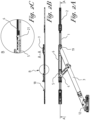
figure 2 shows the fittings shown infig.1 in a condition whereby the leaf is tilted open, wherebyfig.2A, fig.2B, fig.2C show the fittings in a top view, in a longitudinal section according to the line A-A indicated infig. 2A , and in a magnified view the part indicated as B infig.2B ; -
figure 3 schematically shows the components in disassembled condition of the fittings shown infig.1 for hingedly connecting the main arm to the fixed frame; -
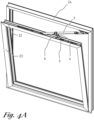
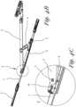
figure 4 schematically shows an embodiment of the fittings according to the invention for a window with a tiltable leaf in a condition whereby the leaf is tilted open with a big tilt opening, wherebyfig.4A ,fig.4B, fig.4C partially show the fittings in mounted condition, in unmounted condition, and in a magnified view the part indicated as E infig.4B respectively; -
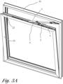
figure 5 schematically shows the fittings shown infig.4 in a condition, whereby the leaf is tilted open with a smaller tilt opening, wherebyfig.5A ,fig.5B, fig.5C show the fittings in mounted condition, in unmounted condition, and in a magnified view the part indicated as F infig.5B respectively; -
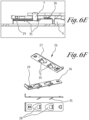
figure 6A schematically and partially shows an embodiment of the fittings according to the invention for a window with a tiltable leaf, wherebyfig.6B, fig.6C, fig.6D ,fig.6E show the longitudinal section in magnified view of the part of the fittings indicated as G infig.6A , in progressive phases of connection of the main arm to the glide piece of the fittings respectively; and wherebyfig.6F shows a component, more specifically the locking element, in different views; -
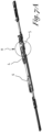
figure 7A schematically shows an embodiment of the fittings according to the invention for a window with a tiltable leaf, wherebyfig.7B, fig.7C, fig.7D partially show the longitudinal section in magnified view of the part of the fittings, indicated as H infig.7A , with different free lengths of the leaf spring of the anti-slam device respectively; -
figure 8 shows an adjustment piece for setting the free length of the leaf spring of the anti-slam device in an embodiment of the fittings according to the invention. - The fittings shown in
figures 1 to 3 are fittings for a window with a fixed frame and a leaf which relative to the fixed frame can be turned around a vertical axis and can be tilted around a horizontal axis and a control of the fittings which is movable from a close position in which the window is closed, to a tilt position for opening the window by a tilt movement of the leaf or to a turn position for opening the window by a turning movement of the leaf.Figure 1 shows the fittings with the leaf opened by turning, such that the leaf forms an angle of 90° with the fixed frame.Figure 2 shows the fittings with the leaf opened by tilting the leaf relative to the fixed frame. - Typically, a leaf is constructed from profiles, for example from aluminium, which on their outside are provided with a fitting groove such that the leaf contains a continuous fitting groove all along its outer contour. Fitting grooves are known and are typically formed by two upright parallel ribs of the profiles which are positioned at a distance from each other and the free edges of which are bent towards each other.
- The fittings shown contain a sliding
slat 1 that is slideably applied in the longitudinal direction in the fitting groove in the horizontal profile at the upperside of the leaf. The slidingslat 1 is workably connected, for example via one or several slidingparts 2 applied in the continuous fitting groove along the contour of the leaf, to the operating mechanism of the control device such that movements of the operating crank of the control device are converted into sliding movements of the slidingslat 1 in the horizontal fitting groove of the leaf. Examples of sliding parts include sliding slats and/or latches that are applied in the vertical and horizontal fitting grooves of the leaf and/or corner transmissions partially protruding in a vertical and partially protruding in a horizontal fitting groove in the corners of the leaf for converting the sliding movement of the sliding parts in the vertical fitting groove to the sliding parts in the horizontal fitting groove and/or vice versa. - To allow the leaf to tilt relative to the fixed frame of the window the fittings contain a scissor mechanism. The scissor mechanism is provided with a
main arm 3 and asupport arm 4. Thesupport arm 4 is hingedly connected at one end to themain arm 3 and at the other end to asupport part 5 that is fixedly mounted in the horizontal fitting groove of the leaf above the slidingslat 1 such that the slidingslat 1 can slide under thesupport part 5 in the fitting groove. Themain arm 3 is provided with acoupling pin 7 at one end for coupling with aglide piece 6 via one of bothcoupling openings 19 provided to that end in the glide piece. Obviously more than twocoupling openings 19 can also be provided on the glide piece. Theglide piece 6 is applied in the horizontal fitting groove longitudinally slideable relative to both the fixedsupport part 5 and the slidingslat 1. This is done such that the slidingslat 1 can slide under theglide piece 6 in the fitting groove and that when opening and closing the window by a tilt movement of the leaf, theglide piece 6 shifts towards or away from, respectively, the fixedsupport part 5 over a stroke of the glide piece, depending on the distance between theglide piece 6 and thesupport part 5 when the scissor mechanism is in closed condition. Said distance between theglide piece 6 and thesupport part 5 depends on the chosencoupling opening 19 in theglide piece 6 in which thecoupling pin 7 is applied for coupling themain arm 3 with the glide piece. It is also conceivable that thesupport part 5 overlaps with theglide piece 6, more specifically in an embodiment whereby thesupport part 5 has an oblong-shaped opening which serves as guide for theglide piece 6. - In closed condition of the scissor mechanism, for example in the close position or in turn position of the window, the latter as shown in
fig.1 , themain arm 3 and thesupport arm 4 are substantially parallel with theglide piece 6 and thesupport part 5. In this condition, theglide piece 6, as also shown infig. 1C , is slid over a certain stroke relative to thesupport part 5. - In opened condition of the scissor mechanism, for example in an open tilt position, as shown in
fig.2 , themain arm 3 andsupport arm 4 form an angle relative to each other and relative to thesupport part 5 and glidepiece 6. In this condition, theglide piece 6, as also shown infig. 2C , is slid up to thesupport part 5. Thesupport part 5 is provided with ananti-slam device 20 which in open tilt position snaps into arelevant notch 21 in the glide piece. The snapped-inanti-slam device 20 ensures a certain resistance against theglide piece 6 and thesupport part 5 moving apart and as such counteracts the leaf slamming shut from an open tilt position, for example due to a gust of wind. Closing the leaf again from an open tilt position is done by exercising sufficient pushing force on the leaf towards the fixed frame such that theanti-slam device 20 snaps out of the glide piece again and theglide piece 6 can shift away from thesupport part 5. - The other end of the
main arm 3 is hingedly connected to the fixed frame of the window. An example of such hinged connection is shown in more detail in disassembled form infig.3 . An end of theleaf arm 8 is hingedly connected to the end of themain arm 3 which in mounted condition of the fittings is located near the vertical axis around which the leaf can be turned. Near its other end theleaf arm 8 is hingedly connected to aframe hinge piece 10 which in turn is hingedly connected to aframe corner part 12 of the fittings which is fixedly applied in a frame groove in the horizontal profile of the fixed frame at the upperside of the window. A frame groove is a fitting groove formed on the inside in the profiles of the fixed frame of the window in which frame parts of the fittings can be applied which cooperate with parts of the fittings applied in the fitting grooves of the leaf. Theleaf arm 8 is also hingedly connected to theframe arm 9 which in turn is hingedly connected to theframe corner part 12 and via aleaf hinge piece 11 to the main arm. Said hinged connection betweenmain arm 8 and fixed frame supports the tilting and turning of the leaf relative to the fixed frame. - The
main arm 3 has the form of a slat whereby said slat shows adouble bend 13. On the level of said double bend 13 aslot 14 is applied in themain arm 3 in the longitudinal direction. Between thedouble bend 13 and the end of themain arm 3 provided with thecoupling pin 7, the main arm is provided with fourholes 15 placed symmetrically relative to each other near the double bend. In one pair of the holes in the longitudinal direction of themain arm 3, anextended protrusion 16 is attached on the underside of the main arm, i.e. the side that, when in use, faces the upperside of the slidingslat 1, using a rivet connection protruding in the direction of the sliding slat. Alternatively, at the side facing the main arm theextended protrusion 16 can also of course be provided with screw openings through which removable screws can be screwed through theholes 15 for attachment of theextended protrusion 16 on themain arm 3. In one of the remainingholes 15, i.e. in the example shown the hole located nearest to thedouble bend 13, separate from the extendedprotrusion 16, ashort protrusion 17 is applied in the transversal direction of themain arm 3, overlapping with theextended protrusion 16 in the longitudinal direction, whereby an opening is formed which is laterally delimited by theshort protrusion 17 and theextended protrusion 16 respectively and at the upperside is delimited by themain arm 3. Theshort protrusion 17 is applied by screwing a removable screw through therelevant hole 15 in ascrew opening 19 formed in theshort protrusion 17 on the side facing the underside of themain arm 3 when in use. If desired, theshort protrusion 17 can be easily moved to another location on the main arm, for example on the level of thehole 15 that is still free by removing the removable screw and attaching theshort protrusion 17 on this other location by screwing the removable screw through said free hole in the screw opening 19 of theshort protrusion 17. - A
peg 18 is provided on the slidingslat 1 with a substantially cylindrical form which in mounted condition of the fittings and with the window closed, protrudes outwardly towards themain arm 3. As the slidingslat 1 is workably connected to the control device, saidpeg 18 shifts together with the control device and thepeg 18 can act as a selection means for selecting a tilt position, a turn position or a close position according to the position of the operating crank. -
Figures 4 and5 show fittings for a tilt window in mounted condition (Fig.4A ,5A ) and in unmounted condition (Fig.4B ,5B ). The fittings shown contain a slidingslat 1 that is longitudinally slideable in thefitting groove 22 in the horizontal profile at the upperside of theleaf 23. The slidingslat 1 is workably connected via slidingparts 2 to the operating mechanism of the control device. To allow theleaf 23 to tilt relative to the fixedframe 24 of the window, the fittings contain a scissor mechanism provided with amain arm 3 and asupport arm 4. Thesupport arm 4 is hingedly connected at one end to themain arm 3 and at the other end to asupport part 5 that is fixedly mounted in the horizontal fitting groove of the leaf above the slidingslat 1 such that the slidingslat 1 can slide under thesupport part 5 in thefitting groove 22. - The
glide piece 6 is applied in the horizontalfitting groove 22, longitudinally slideable relative to both the fixedsupport part 5 and the slidingslat 1. The glide piece is provided with twocoupling openings 19 separated from each other in a longitudinal direction. At one end, themain arm 3 is hingedly connected to the fixedframe 24 and at the other end is provided with acoupling pin 7 for coupling with aglide piece 6 via one of bothcoupling openings 19 provided to that end in the glide piece. Themain arm 3 is hingedly connected to theglide piece 6 with thecoupling pin 7, via thecoupling opening 19 located nearest thesupport part 5 infig. 4 , and via thecoupling opening 19 located furthest from thesupport part 5 infig.5 respectively. - When opening and closing the window by a tilt movement of the leaf, the
glide piece 6 shifts towards or away from, respectively, the fixedsupport part 5 over a stroke of the glide piece, depending on the chosencoupling opening 19 in theglide piece 6 in which thecoupling pin 7 is applied for coupling themain arm 3 with the glide piece. Said stroke and correspondingly the tilt opening, is greater in the example shown infig.4 than infig.5 . -
Figure 6 shows an example of coupling themain arm 3 of the scissor mechanism of the fittings with theglide piece 6 by applying thecoupling pin 7 in a selectedcoupling opening 19.Fig.6B shows theglide piece 6 and themain arm 3 in uncoupled condition. In this example, theglide piece 6 is provided with twocoupling openings 19, whereby the selected coupling opening for coupling themain arm 3 is the coupling opening which, when in use, is located nearest to thesupport part 5 which is applied in a certain position in thefitting groove 22, such that when tilting the window, the support part does not shift relative to the leaf. Said certain position can be a fixed position but can also be adjustable and for example be set when mounting the fittings or when adjusting the window during installation or at a later time. Thecoupling pin 7 protrudes from themain arm 3 and near its free end at its outer contour is provided with a ring-shapednotch 25. The fittings comprise a lockingelement 26, see alsofig.6F , with a substantially flat plate-shapedsection 27 in which twopassages 28 are applied in this example. Near each of thepassages 28 the plate-shapedsection 27 is provided with alip 35 that protrudes downwardly relative to the plate-shaped section and at least partially overlaps with therelevant passage 28. Thelips 35 protrude obliquely according to a certain profile and form an angle with the plate-shapedsection 27. - On the side opposite the side which, when in use, faces the
support part 5, theglide piece 6 is provided with a groove in which, as shown infig.6C , the plate-shapedsection 27 of the lockingelement 26 is inserted such that thepassages 28 align with thecoupling openings 19. This allows thecoupling pin 7 to be applied in the selectedcoupling opening 19, whereby the coupling pin protrudes through thecorresponding passage 28 of the lockingelement 26. When inserting thecoupling pin 7 through thecoupling opening 19 in theglide piece 6 and thecorresponding passage 28 in the lockingelement 26, the underside of the coupling pin touches the sloping plane of thecorresponding lip 35. When pushing further downward, as shown infig. 6D , a force is created which causes the lockingelement 26 to slide up into the position that the ring-shapednotch 25 of thecoupling pin 7 snaps into the edge of the lockingelement 26 delimiting the passage, as shown infig. 6E . Simultaneously, aprotrusion 29 of the lockingelement 26 snaps into a complementary notch in the groove of theglide piece 6 and the hinged connection between themain arm 3 and the glide piece is firmly locked. The lockingelement 26 is further provided with astop 36 at the inserted end, such that the lockingelement 26 cannot unintentionally be removed from theglide piece 6. -
Figures 6B to 6E successively show the steps of 'automatically locking' when pushing in. In this way it is ensured that the installer cannot forget to lock the connection. Uncoupling is manual and thus requires a deliberate action. -
Figure 7 shows an example of ananti-slam device 20 of the fittings to prevent closing of the scissor mechanism and the associated unintentional slamming shut of the window from an open tilt position. The figure shows theanti-slam device 20 in a condition, whereby the scissor mechanism is closed and theglide piece 6 and supportpart 5 are arranged separate and at a distance from each other, in other words, theanti-slam device 20 does not snap into therelevant notch 21 in theglide piece 6. - The
anti-slam device 20 comprises an oblong-shapedleaf spring 30, which at one end is connected to thesupport part 5 and extends freely lengthways beyond thesupport part 5 in the direction of theglide piece 6 and protrudes beyond the side of the support part facing theglide piece 6. At its free end, theleaf spring 30 is curved and is provided with adouble bend 31 near the free end. - In open tilt position of the window the free end of the
leaf spring 30 snaps into thenotch 21 in the glide piece. Snapping out theleaf spring 30 again is done by exercising a force to slide theglide piece 6 away from thesupport part 5 which is greater than the counteracting spring force generated by the elastic deformation of theleaf spring 30. The spring force depends on the free length of theleaf spring 30. The free length of the leaf spring is chosen depending on the desired resistance against the window slamming shut from the open tilt position and in the example shown is adjustable. To this end, twotransverse grooves 32 which extend over the full width of thesupport part 5 are provided in thesupport part 5 at the upperside under the freely extendingleaf spring 30. This allows anadjustment piece 33, as shown for example infig.8 , to be fittingly inserted into one of the transverse grooves. Theadjustment piece 33 is provided on the side facing theleaf spring 30, when in use, with a substantiallyU-shaped groove 34, whereby theleaf spring 30, when theadjustment piece 33 is inserted into one of thetransverse grooves 32, rests on the bottom of theU-shaped groove 34 and is clamped laterally by the opposite edges of thegroove 34. -
Fig.7B shows theanti-slam device 20 without insertedadjustment piece 33 in one of thetransverse grooves 32. Here the leaf spring has the maximum free length.Fig.7C shows theanti-slam device 20 with the adjustment piece inserted in thetransverse groove 32 located nearest to the end of theleaf spring 30 that is connected to thesupport part 5. In inserted condition, theadjustment piece 33 is clamped between theleaf spring 30 and thesupport part 5. This means theleaf spring 30 has a smaller free length such that the slam resistance increases.Fig.7D shows theanti-slam device 20 with theadjustment piece 33 inserted in the othertransverse groove 32 and the leaf spring has the shortest adjustable free length. - The present invention is by no means limited to the embodiments described as an example and shown in the drawings, but fittings according to the invention for a window with a fixed frame and a tiltable leaf can be realised in all kinds of forms and dimensions, without departing from the scope of the invention.
Claims (14)
- Fittings for a window with a fixed frame (24) and a tiltable leaf (23) around a horizontal axis, said fittings comprisinga support part (5) that can be fixedly attached in a relevant fitting groove (22) along an outer contour of the leafa glide piece (6) that is slideable relative to the support part,a main arm (3) that at one end can be hingedly connected to the fixed frame and at the other end can be provided with a coupling pin (7) for a hinged connection to the glide piece (6), anda support arm (4) that can be hingedly connected to the support part at one end and at the other end is hingedly connected to the main arm, whereby the fittings are configured such that, when in use, in the close position of the window, the main arm and the support arm are substantially parallel with the glide piece and the support part and in the open tilt position, the main arm and support arm form an angle relative to each other and relative to the support part and the glide piece, characterised in thatwhen in use, when moving the leaf from the close position to the open tilt position or vice versa the support part and the glide piece move relative to each other over a predefined stroke of the glide piece, andthe glide piece in longitudinal direction is provided at its upperside with several coupling openings (19) in which the coupling pin can be selectively applied for hingedly connecting the main arm with the glide piece, whereby the stroke of the glide piece and correspondingly, the tilt opening is determined depending on the coupling opening selected for the connection.
- The fittings according to claim 1, characterised in that the coupling pin (7) is provided with a ring-shaped notch (25) and can be applied in the selected coupling opening (19), such that the coupling pin protrudes through a passage (28) of a locking element (26) of the glide piece (6), whereby the ring-shaped notch (25) of the coupling pin snaps into the edge of the locking element delimiting the passage (28).
- The fittings according to claim 2, characterised in that the locking element (26) comprises several passages (28) and a plate-shaped section (27), in which the passages (28) are applied and that the glide piece (6) is provided at one side with a groove for fittingly inserting the plate-shaped section of the locking element such that the passages align with the corresponding coupling openings (19).
- The fittings according to claim 3, characterised in that the locking element (26), for every passage (28) comprises a lip (35) that protrudes downwardly relative to the plate-shaped section (27) and at least partially overlaps with the passage.
- The fittings according to claim 4, characterised in that the lip (35) forms an angle with the plate-shaped section (27) .
- The fittings according to any one of the claims 3 to 5, characterised in that the plate-shaped section (27) of the locking element (26) is provided with a protrusion (29) complementary to a notch in the groove of the glide piece (6), configured such that in inserted condition of the locking element with the coupling pin (7) snapped into the locking element, the protrusion engages with the notch to lock the locking element.
- The fittings according to claim 1, characterised in that the fittings are provided with an anti-slam device (20) comprising an oblong-shaped leaf spring (30), that at one end is connected to the support part (5) and extends freely lengthways beyond the support part in the direction of the glide piece (6), whereby in open tilt position of the window, the other end of the leaf spring snaps into the glide piece to prevent the window from slamming shut.
- The fittings according to claim 7, characterised in that the leaf spring (30) is curved at its free end and in open tilt position snaps into a notch (21) provided at the underside of the glide piece (6) with its curved end.
- The fittings according to claim 7 or 8, characterised in that the leaf spring (30) is provided with a double bend (31) near its free end.
- The fittings according to any one of the claims 7 to 9, characterised in that the free length of the leaf spring (30) is adjustable.
- The fittings according to claim 10, characterised in that the support part(5) at the upperside under the freely extending leaf spring (30) is provided with a transverse groove (32) over at least a substantial part of the width of the support part, in which an adjustment piece (33) can be fittingly inserted laterally, whereby the adjustment piece is clamped between the leaf spring and the support part (5) in inserted condition and as such decreases the free length of the leaf spring such that the slam resistance increases.
- The fittings according to claim 11, characterised in that the support part (5) at the upperside under the freely extending leaf spring (30) is provided with several parallel transverse grooves (32) over at least a substantial part of the width of the support part (5) in which the adjustment piece (33) can selectively be fittingly inserted laterally, whereby in the selected transverse groove the adjustment piece in inserted condition is clamped between the leaf spring and the support part and as such the slam resistance is set.
- The fittings according to claim 11 or 12, characterised in that the adjustment piece (33) is provided with a substantially U-shaped groove (34) on the side facing the leaf spring, when in use, configured such that in inserted condition the leaf spring rests on the bottom of the groove and is clamped laterally by the opposite edges of the U-shaped groove.
- The fittings according to any one of the claims 7 to 13, characterised in that the support part (5) is provided with a threaded hole and the leaf spring (30) is provided with a screw passage through which a screw can be screwed in the threaded hole to connect the leaf spring with the support part.
Applications Claiming Priority (1)
| Application Number | Priority Date | Filing Date | Title |
|---|---|---|---|
| BE20236055A BE1032267B1 (en) | 2023-12-22 | 2023-12-22 | Fittings for a tilt window |
Publications (3)
| Publication Number | Publication Date |
|---|---|
| EP4575156A1 true EP4575156A1 (en) | 2025-06-25 |
| EP4575156B1 EP4575156B1 (en) | 2026-02-25 |
| EP4575156C0 EP4575156C0 (en) | 2026-02-25 |
Family
ID=89474312
Family Applications (1)
| Application Number | Title | Priority Date | Filing Date |
|---|---|---|---|
| EP24220586.2A Active EP4575156B1 (en) | 2023-12-22 | 2024-12-17 | Fittings for a tilt window |
Country Status (3)
| Country | Link |
|---|---|
| EP (1) | EP4575156B1 (en) |
| CN (1) | CN120193718A (en) |
| BE (1) | BE1032267B1 (en) |
Citations (4)
| Publication number | Priority date | Publication date | Assignee | Title |
|---|---|---|---|---|
| DE2023535A1 (en) | 1970-05-14 | 1971-12-23 | WiIh Frank GmbH, 7022 Leinfelden | Upper edge bracket for a swivel tilt sash of a window of a door or the like |
| US20050284025A1 (en) | 2004-06-28 | 2005-12-29 | Savio S.P.A. | Upper articulation assembly for windows and doors with wing and swivel wing opening |
| EP2020476A2 (en) | 2007-05-10 | 2009-02-04 | W. HAUTAU GmbH | Conductor component mountable without the use of tools |
| US8161683B2 (en) | 2008-01-17 | 2012-04-24 | Remi Emiel Van Parys | Metalwork of a window and elements thereof |
-
2023
- 2023-12-22 BE BE20236055A patent/BE1032267B1/en active IP Right Grant
-
2024
- 2024-12-17 EP EP24220586.2A patent/EP4575156B1/en active Active
- 2024-12-20 CN CN202411893641.4A patent/CN120193718A/en active Pending
Patent Citations (4)
| Publication number | Priority date | Publication date | Assignee | Title |
|---|---|---|---|---|
| DE2023535A1 (en) | 1970-05-14 | 1971-12-23 | WiIh Frank GmbH, 7022 Leinfelden | Upper edge bracket for a swivel tilt sash of a window of a door or the like |
| US20050284025A1 (en) | 2004-06-28 | 2005-12-29 | Savio S.P.A. | Upper articulation assembly for windows and doors with wing and swivel wing opening |
| EP2020476A2 (en) | 2007-05-10 | 2009-02-04 | W. HAUTAU GmbH | Conductor component mountable without the use of tools |
| US8161683B2 (en) | 2008-01-17 | 2012-04-24 | Remi Emiel Van Parys | Metalwork of a window and elements thereof |
Also Published As
| Publication number | Publication date |
|---|---|
| EP4575156B1 (en) | 2026-02-25 |
| BE1032267B1 (en) | 2025-07-23 |
| BE1032267A1 (en) | 2025-07-16 |
| EP4575156C0 (en) | 2026-02-25 |
| CN120193718A (en) | 2025-06-24 |
Similar Documents
| Publication | Publication Date | Title |
|---|---|---|
| US20070220705A1 (en) | Damper arrangement | |
| US8429794B2 (en) | Adjustable door hinge | |
| US7240974B2 (en) | Folding cover | |
| US7900322B2 (en) | Friction hinge for push-out style window | |
| KR101968628B1 (en) | Pivot hinge apparatus | |
| CA2904883A1 (en) | Adjustable curved door assembly | |
| DK182232B1 (en) | Roof window with a lifting device, method of assembling the roof window and method of adjusting the lifting device of the roof window. | |
| EP4575156B1 (en) | Fittings for a tilt window | |
| CA3053127C (en) | Window vent assist mechanism for vent window assembly | |
| CN208518498U (en) | A kind of invisible hinge inner side opening and lower hanging hardware system | |
| IL278631B2 (en) | A method for axially attaching a furniture cover to a furniture body using a cover adjustment | |
| EP2326782B1 (en) | A window balance arm, a window hinge assembly and a window assembly | |
| ES2955583T3 (en) | Support fitting for a tilting sash of a window or door | |
| EP1602883A2 (en) | Door hinge | |
| CN112681915B (en) | Angle-adjustable corner hinge | |
| EP4575158A1 (en) | Adjustment system for the fittings of a tilt and/or turn window | |
| EP2821577A1 (en) | Operating device for a tilt and turn door or window | |
| EP1828515B1 (en) | Adjustable door hinge | |
| RU2775117C2 (en) | Flap fittings for piece of furniture, sidewall of furniture case, and piece of furniture with sidewall | |
| CN116791989B (en) | A concealed hinged bottom hinge | |
| RU2832011C1 (en) | Furniture hinge for hinged attachment of furniture door or flap to furniture body and piece of furniture with such furniture hinge | |
| CN121941826A (en) | Fitting for sliding/tilting window | |
| JP4392802B2 (en) | Raising and lowering window | |
| WO2010007641A2 (en) | Easy to handle pivoting wing blind positionable in a desired degree of opening | |
| JP7067790B2 (en) | Ventilation system |
Legal Events
| Date | Code | Title | Description |
|---|---|---|---|
| PUAI | Public reference made under article 153(3) epc to a published international application that has entered the european phase |
Free format text: ORIGINAL CODE: 0009012 |
|
| STAA | Information on the status of an ep patent application or granted ep patent |
Free format text: STATUS: THE APPLICATION HAS BEEN PUBLISHED |
|
| AK | Designated contracting states |
Kind code of ref document: A1 Designated state(s): AL AT BE BG CH CY CZ DE DK EE ES FI FR GB GR HR HU IE IS IT LI LT LU LV MC ME MK MT NL NO PL PT RO RS SE SI SK SM TR |
|
| STAA | Information on the status of an ep patent application or granted ep patent |
Free format text: STATUS: REQUEST FOR EXAMINATION WAS MADE |
|
| 17P | Request for examination filed |
Effective date: 20250715 |
|
| GRAP | Despatch of communication of intention to grant a patent |
Free format text: ORIGINAL CODE: EPIDOSNIGR1 |
|
| STAA | Information on the status of an ep patent application or granted ep patent |
Free format text: STATUS: GRANT OF PATENT IS INTENDED |
|
| INTG | Intention to grant announced |
Effective date: 20251022 |
|
| GRAS | Grant fee paid |
Free format text: ORIGINAL CODE: EPIDOSNIGR3 |
|
| GRAA | (expected) grant |
Free format text: ORIGINAL CODE: 0009210 |
|
| STAA | Information on the status of an ep patent application or granted ep patent |
Free format text: STATUS: THE PATENT HAS BEEN GRANTED |
|
| AK | Designated contracting states |
Kind code of ref document: B1 Designated state(s): AL AT BE BG CH CY CZ DE DK EE ES FI FR GB GR HR HU IE IS IT LI LT LU LV MC ME MK MT NL NO PL PT RO RS SE SI SK SM TR |
|
| REG | Reference to a national code |
Ref country code: CH Ref legal event code: F10 Free format text: ST27 STATUS EVENT CODE: U-0-0-F10-F00 (AS PROVIDED BY THE NATIONAL OFFICE) Effective date: 20260225 Ref country code: GB Ref legal event code: FG4D |
|
| REG | Reference to a national code |
Ref country code: DE Ref legal event code: R096 Ref document number: 602024002837 Country of ref document: DE |
|
| REG | Reference to a national code |
Ref country code: IE Ref legal event code: FG4D |
|
| U01 | Request for unitary effect filed |
Effective date: 20260225 |
|
| U07 | Unitary effect registered |
Designated state(s): AT BE BG DE DK EE FI FR IT LT LU LV MT NL PT RO SE SI Effective date: 20260304 |