EP4575115A1 - Air gap shield - Google Patents
Air gap shield Download PDFInfo
- Publication number
- EP4575115A1 EP4575115A1 EP23219374.8A EP23219374A EP4575115A1 EP 4575115 A1 EP4575115 A1 EP 4575115A1 EP 23219374 A EP23219374 A EP 23219374A EP 4575115 A1 EP4575115 A1 EP 4575115A1
- Authority
- EP
- European Patent Office
- Prior art keywords
- horizontal section
- shaped bracket
- air gap
- preferred
- section
- Prior art date
- Legal status (The legal status is an assumption and is not a legal conclusion. Google has not performed a legal analysis and makes no representation as to the accuracy of the status listed.)
- Pending
Links
Images

Classifications
-
- E—FIXED CONSTRUCTIONS
- E04—BUILDING
- E04B—GENERAL BUILDING CONSTRUCTIONS; WALLS, e.g. PARTITIONS; ROOFS; FLOORS; CEILINGS; INSULATION OR OTHER PROTECTION OF BUILDINGS
- E04B1/00—Constructions in general; Structures which are not restricted either to walls, e.g. partitions, or floors or ceilings or roofs
- E04B1/62—Insulation or other protection; Elements or use of specified material therefor
- E04B1/92—Protection against other undesired influences or dangers
- E04B1/94—Protection against other undesired influences or dangers against fire
- E04B1/947—Protection against other undesired influences or dangers against fire by closing openings in walls or the like in the case of fire
-
- E—FIXED CONSTRUCTIONS
- E04—BUILDING
- E04F—FINISHING WORK ON BUILDINGS, e.g. STAIRS, FLOORS
- E04F13/00—Coverings or linings, e.g. for walls or ceilings
- E04F13/07—Coverings or linings, e.g. for walls or ceilings composed of covering or lining elements; Sub-structures therefor; Fastening means therefor
- E04F13/08—Coverings or linings, e.g. for walls or ceilings composed of covering or lining elements; Sub-structures therefor; Fastening means therefor composed of a plurality of similar covering or lining elements
- E04F13/0801—Separate fastening elements
- E04F13/0832—Separate fastening elements without load-supporting elongated furring elements between wall and covering elements
- E04F13/0833—Separate fastening elements without load-supporting elongated furring elements between wall and covering elements not adjustable
- E04F13/0835—Separate fastening elements without load-supporting elongated furring elements between wall and covering elements not adjustable the fastening elements extending into the back side of the covering elements
-
- E—FIXED CONSTRUCTIONS
- E04—BUILDING
- E04B—GENERAL BUILDING CONSTRUCTIONS; WALLS, e.g. PARTITIONS; ROOFS; FLOORS; CEILINGS; INSULATION OR OTHER PROTECTION OF BUILDINGS
- E04B1/00—Constructions in general; Structures which are not restricted either to walls, e.g. partitions, or floors or ceilings or roofs
- E04B1/62—Insulation or other protection; Elements or use of specified material therefor
- E04B1/74—Heat, sound or noise insulation, absorption, or reflection; Other building methods affording favourable thermal or acoustical conditions, e.g. accumulating of heat within walls
- E04B1/76—Heat, sound or noise insulation, absorption, or reflection; Other building methods affording favourable thermal or acoustical conditions, e.g. accumulating of heat within walls specifically with respect to heat only
- E04B1/7608—Heat, sound or noise insulation, absorption, or reflection; Other building methods affording favourable thermal or acoustical conditions, e.g. accumulating of heat within walls specifically with respect to heat only comprising a prefabricated insulating layer, disposed between two other layers or panels
- E04B1/7612—Heat, sound or noise insulation, absorption, or reflection; Other building methods affording favourable thermal or acoustical conditions, e.g. accumulating of heat within walls specifically with respect to heat only comprising a prefabricated insulating layer, disposed between two other layers or panels in combination with an air space
-
- E—FIXED CONSTRUCTIONS
- E04—BUILDING
- E04B—GENERAL BUILDING CONSTRUCTIONS; WALLS, e.g. PARTITIONS; ROOFS; FLOORS; CEILINGS; INSULATION OR OTHER PROTECTION OF BUILDINGS
- E04B1/00—Constructions in general; Structures which are not restricted either to walls, e.g. partitions, or floors or ceilings or roofs
- E04B1/38—Connections for building structures in general
- E04B1/388—Separate connecting elements
- E04B2001/389—Brackets
-
- E—FIXED CONSTRUCTIONS
- E04—BUILDING
- E04F—FINISHING WORK ON BUILDINGS, e.g. STAIRS, FLOORS
- E04F2290/00—Specially adapted covering, lining or flooring elements not otherwise provided for
- E04F2290/04—Specially adapted covering, lining or flooring elements not otherwise provided for for insulation or surface protection, e.g. against noise, impact or fire
- E04F2290/045—Specially adapted covering, lining or flooring elements not otherwise provided for for insulation or surface protection, e.g. against noise, impact or fire against fire
Definitions
- the invention relates to an L-shaped bracket for a cavity barrier, an air gap shield system, and the use thereof for closing a cavity to improve fire protection of a ventilated façade.
- Present invention also relates a building construction comprising the air gap shield system.
- Ventilated façades require cavity barriers, such as ventilated and non-ventilated barriers, that would, in case of a fire, prevent the fire moving from bottom of the façade to the top. For example, in case of a broken window, the fire can spread over the air gap between the insulation layer and the cladding of the façade and move upwards.
- brackets on the market require shaping/bending and producing the desired L-shape of the bracket on site.
- intumescent material there is also a need to attach the intumescent material to the cavity barrier in a separate step.
- Many cavity barrier systems known in the art also are limited to a certain size of the air gap, such as air gap of 25 mm or less. This is usually limited by the bracket, which cannot support larger sizes of cavity barriers.
- bracket In the first typical method, generally a bracket must be pushed through the intumescent strip to fix the intumescent strip together with the barrier to the wall, such as butterfly bending of the bracket.
- the disadvantage of such method is that the full shielding function of the cavity barrier is not possible because the intumescent material would not be able to fully expand in the area of the bracket fixation.
- the bracket In the second method, generally the bracket goes into the mineral wool part of the barrier only and the intumescent strip must be attached to the mineral wool of the barrier in a separate step using fixation such as a spring like screws. In turn, the cladding panel is then able to keep the barrier in the intended position.
- the bracket In the second method where the bracket is pushed into the cavity barrier only, there is no protection against the cavity barrier moving away from the surface of the wall.
- the cavity barrier may start slipping off the smooth bracket, which itself may also start to droop.
- this may become a critical issue, since the cavity barrier can be exposed to weather conditions, such as rain, wind, and thunderstorms.
- the object of the present invention is to provide a bracket or a bracket and a cavity barrier solution that solves the problems existing the art as outlined above, such as solving the problem of time consuming preinstallation and installation methods, poor stability of the bracket, fixation of the intumescent strip to the cavity barrier, and limited application in view of the size of the air gap between the insulation layer and the cladding.
- the Present invention relates to an L-shaped bracket for a cavity barrier that can be used in a ventilated façade.
- the L-shaped bracket according to the present invention has a vertical section and a horizontal section. According to the present invention the vertical section is intended for fixing to a substrate, such as an exterior wall surface. It is also preferred that the L-shaped bracket according to the present invention is used for fixing to an interior wall surface.
- the horizontal section of the L-shaped bracket is used for inserting into the cavity barrier.
- the horizontal section of the L-shaped bracket comprises at least one tab extending out in a vertical direction relative to the horizontal section and/or wherein at least one edge of the horizontal section in the longitudinal direction is flipped downward away from the inside of the L-shaped bracket at about 90 degrees measured from the horizontal section, wherein the at least one flipped edge of the horizontal section is wider in the vertical direction towards the inside of the L-shaped bracket in relation to the flipped edge of the horizontal section towards the end of the horizontal section.
- vertical direction relates to up or down relative to a horizonal plane, in present case the horizontal section.
- the at least one tab serves the purpose of securing the cavity barrier on the L-shaped bracket of the present invention.
- the cavity barrier would not be able to slip off the L-shaped bracket after a prolonged period of time, such as in case of construction stop or harsh weather conditions, such as rain, wind and thunderstorms.
- the at least one flipped edge of the horizontal section aids in the stability of the L-shaped bracket.
- the length of the vertical section ranges from 80 to 200 mm, more preferably 100 to 160 mm.
- the length of the horizontal section ranges from 80 to 500 mm, more preferably from 100 to 400 mm, more preferably from 110 to 300 mm.
- the L-shaped bracket for a cavity barrier would be suitable and have the required fire stop performance for air gaps in ventilated façades that are less than 25 mm, more preferably greater than or equal to 25 mm, more preferably greater than 35 mm, more preferably greater than or equal to 50 mm, more preferably greater than 55 mm. It is preferred that the L-shaped bracket for a cavity barrier would be suitable and have the required fire stop performance for air gaps in ventilated façades in the range of from 25 mm to 55 mm, more preferably in the range of from 35 mm to 50 mm.
- the at least one tab is stamped out and bent out of the horizontal section at an angle. It is preferred that the at least one tab is bent out of the horizontal section at less than 90 degrees, preferably less than 45 degrees, measured from the horizontal section in the direction of the bend. It is preferred that the at least one tab is manufactured by a sheet metal stamping process using a progressive die set. In such a process, it is typical that first slots are blanked in the metal strip (e.g. horizontal section) and then the tab geometry is cut and the tabs are bent into their final positions angled relative to the plane of the metal strip.
- the direction of the at least one tab, preferably two tabs, extending out of the horizontal section produces a harpoon type arrangement, such that the at least one tab, preferably two tabs, extends out and bends out from the horizonal section in the opposite direction from the insertion direction, i.e. the direction the horizontal section is inserted into the cavity barrier. It is preferred that the at least one tab is bent out of the horizonal section at an angle, wherein the angle is open in the direction opposite of the insertion direction.
- Such harpoon type arrangement of at least one tab, preferably two tabs, on the horizontal section of the L-shaped bracket allows for a better securing of the cavity barrier. Specifically, the material of the cavity barrier, such as mineral wool, gets caught on the harpoon type arrangement of the at least one tab which does not allow the cavity barrier to slip off the L-shaped bracket.
- the horizontal section of the L-shaped bracket comprises two tabs.
- the horizontal section of the L-shaped bracket comprises two tabs
- the two tabs extend out of the horizontal section in the vertical direction in the opposite directions relative to the horizonal section.
- the first tab is bent into the horizontal section, and the other, second tab, is bend out of the horizontal section, relative to the first tap.
- the tab closest to the end of the horizontal section extends up or down relative to the horizontal section, and the tab closest to the inside corner, where the horizonal section meets the vertical section of the L-shaped bracket, extends up or down relative to the horizontal section, wherein the two tabs are extended out of the horizontal section in the opposite direction of each other relative to the horizontal section.
- the direction of the two tabs extending out of the horizontal section produces a harpoon type arrangement, such that the two tabs, extend out and bend out from the horizonal section in the opposite direction of the insertion direction, i.e. the direction of the insertion into the cavity barrier. Having the tabs bend out in a harpoon type arrangement and in the opposite directions from each other relative to the horizontal section would further promote the secure fixing of the cavity barrier on the L-shaped bracket according to the present invention.
- the horizontal section of the L-shaped bracket comprises 3 to 8 tabs.
- the tabs are bent out of the horizontal section in alternating directions of up and down relative to each other as described herewith. In case where there are more than two tabs present on the horizontal section, it is preferred that the tabs are bend out in a harpoon type arrangement as outlined herewith.
- the shape of the stamped tab is trapezoidal, preferably isosceles trapezoid, wherein out of the two parallel sides, the narrower side is the one that stays attached to the horizontal section of the L-shaped bracket and the wider parallel side of the isosceles trapezoid is the one that is bent out of the horizontal section, either in the upward or the downward direction relative to the horizontal section of the L-shaped bracket.
- Present invention is not limited to a single shape of the at least one tab and it is possible to use any conceivable shape of the at least one tab, such as square, rectangular, triangular, semicircular, semioval or irregular shape.
- the vertical section of the L-shaped bracket comprises at least one opening, preferably two openings, more preferably three or four openings, intended for fastening means. It is preferred that the openings are of a circular shape, but can be of any other shape as well, such as square, rectangular, triangular, trapezoidal or other suitable geometric shapes. Said at least one opening is suitable for fastening means such as screws and/or anchors. It is preferred that there are at least two openings on the vertical section of the L-shaped bracket. In another embodiment, it is preferred that the vertical section does not comprise any openings intended for fastening means, such that the L-shaped bracket of the present invention can be attached to the substrate or a wall using direct fastening means only.
- the vertical section of the L-shaped bracket is suitable to be fastened directly to a substrate or a wall, allowing more flexibility for a skilled worker to be able to decide the exact position of the vertical section that should be fastened to a substrate or a wall, which is not predetermined with an opening.
- the vertical section of the L-shaped bracket comprises two openings, it is preferred that said openings are arranged in such a way that there is enough space to directly fasten either between, above or below the two openings. Same would apply if there was only one opening on the vertical section of the L-shaped bracket, such that it would be possible to use direct fastening either above or below the only opening on the vertical section of the L-shaped bracket.
- the L-shaped bracket it attached to a surface in its intended "L” shape.
- the bracket is installed in the sideway shape of "L", where the horizontal section is above the vertical section.
- the end of the horizontal section is sloped into a point. It is preferred that the end of the horizontal section has a triangular shape, having an acute angular pointed end. Thus, the pointed end of the horizontal section would allow for an easier insertion into the cavity barrier. This would allow for a more seamless and easy installation of the cavity barrier onto the L-shaped bracket, and thus onto the substrate or a wall.
- the horizontal section has a blunt rectangular end. It is also preferred that the horizontal section narrows into a rounded or blunt rectangular end. It is also preferred that the end of the horizontal section has a toothed end, comprising at least two pointed teeth.
- the horizontal section and/or the vertical section of the L-shaped bracket comprises at least one rib, alternatively 2 or 3 ribs, running along in the direction of the horizontal section and/or vertical section of the L-shaped bracket. It is preferred that the at least one rib is punched out in the direction away from the inner corner of the L-shaped bracket. In another embodiment it is preferred that the rib is punched out in the direction toward the inner corner of the L-shaped bracket. It is preferred that the at least one rib runs in the middle of the horizontal section and/or of the vertical section. It is also preferred that the majority of the at least one rib, preferably at least 60 % based on the entire length of the rib is on the horizontal section of the L-shaped bracket.
- the at least one rib runs continuously starting at about the middle or less of the vertical section, measured from the inner angle of the L-shaped bracket, to the middle or less of the horizontal section, measured from the inner angle of the L-shaped bracket.
- the at least one rib of any one of the embodiments as disclosed herewith provides extra stability to the L-shaped bracket, allowing it to maintain its right-angled shape and not droop, especially in harsh weather conditions, such as rain, wind, and thunderstorms.
- the stability added by the at least one rib allows the L-shaped bracket to have a better performance over a longer period of time than the brackets and air gap shield systems that are currently on the market.
- the at least one rib runs continuously and is not interrupted by at least one tab and at least one opening.
- the at least one rib does not go through any tabs or any openings.
- the at least one rib goes through at least one tab and/or at least one opening.
- the at least one flipped edge of the horizontal section comprises at least one protruding element, preferably 2 to 10 protruding elements, extending out of the flipped edge.
- the at least one protruding element, preferably 2 to 10 protruding elements can extend out in the horizontal direction and/or vertical direction from the at least one flipped edge of the horizontal section.
- the at least one protruding element, preferably 2 to 10 protruding elements is arranged on the horizontal section between the inside of the L-shaped bracket until about the middle of the horizontal section of the L-shaped bracket, preferably three quarters toward the middle of the horizontal section of the L-shaped bracket.
- the at least one protruding element preferably 2 to 10 protruding elements, form a zig-zag toothed surface.
- the zig-zagged toothed surface can be any imaginable organization of the protruding elements, having the same or different sizes and/or shapes.
- the at least one protruding element will allow the horizontal section to hold on to the cavity barrier and prevent it from slipping or sliding off.
- the at least one flipped edge of the horizontal section is wider in the vertical direction towards the inside of the L-shaped bracket in relation to the flipped edge of the horizontal section towards the end of the horizontal section. It is preferred that the at least one flipped edge of the horizontal section is narrower in the vertical direction towards the end of the L-shaped bracket in relation to the flipped edge of the horizontal section towards the inside of the L-shaped bracket. This difference creates a slope, wherein the horizontal section is wider in the vertical direction towards the inside of the L-shaped bracket compared to the end of the horizontal section of the L-shaped bracket. Having a wider flipped edge in the vertical direction towards the inside of the L-shaped bracket allows the flipped edge to rest on the surface of the wall, providing extra support and stability to the L-shaped bracket for it to hold the cavity barrier.
- At least a portion of the at least one flipped edge of the horizontal section in the longitudinal direction is flipped a second time at about 90 degrees in the same direction of the first flip, preferably creating an open hem that has edges of bending that are about 90 degrees.
- both edges of the horizontal section in the longitudinal direction are flipped downward away from the inside of the L-shaped bracket at about 90 degrees measured from the horizontal section.
- both edges, preferably the entire length of the edges, of the horizontal section in the longitudinal direction are flipped a second time at about 90 degrees in the same direction of the first flip creating a semiclosed or closed volume. It is preferred that both edges of the horizontal section in the longitudinal direction are flipped a second time at about 90 degrees in the same direction of the first flip creating a semiclosed or closed volume starting at about the middle of the horizontal section and ending towards the end of the horizontal section. It is preferred that the flipped twice edge of the horizontal section creates a closed hem towards the end of the horizontal section, and have an open hem, having edges of bending that are about 90 degrees, towards the inside of the L-shaped bracket of the horizontal section, preferably the middle of the horizonal section.
- the folded twice edges of the horizontal section create a volume, more preferably towards the end of the horizontal section, that assists in the compression of the cavity barrier, thus preventing the cavity barrier from slipping off the horizontal section of the L-shaped bracket.
- at least one edge of the horizontal section in the longitudinal direction and/or at least one edge of the vertical section in the longitudinal direction are flipped inward (i.e. towards the inside of the L-shaped bracket) into a U-shape at about 90 degrees measured from the horizontal section and/or from the vertical section.
- the at least one flipped inward edge of the horizontal and/or vertical section give even more stability to the L-shaped bracket, allowing it to perform and keep its shape for a longer period of time and under harsh weather conditions, such as rain, wind and thunderstorms. It is preferred that both edges of the horizontal section in the longitudinal direction and both edges of the vertical section in the longitudinal direction are flipped inward towards the inside of the L-shaped bracket into a U-shape at about 90 degrees measured from the horizonal and vertical section. It is preferred that the width of the flipped edges is the same width along the horizonal section and/or vertical section.
- the at least one edge of the horizontal and/or vertical section preferably both edges of the horizontal section in the longitudinal direction and both edges of the vertical section in the longitudinal direction, as disclosed herewith are flipped at about 90 degrees away from the inside of the L-shaped bracket. It is preferred that the width of the flipped edges away from the inside of the L-shaped bracket is the same width along the horizonal section and/or vertical section.
- the horizontal section of the L-shaped bracket has a thickness in the vertical direction.
- the vertical section of the L-shaped bracket has a thickness in the horizontal direction.
- the L-shaped bracket is made of a single piece of metal (i.e. sheet of metal), preferably stainless steel, galvanized steel or aluminum alloy. It is preferred that the thickness of the piece of metal is the same throughout. In another embodiment, it is preferred that the piece of metal is thicker where the bend of the L-shape is installed for improving stability of the L-shaped bracket.
- Present invention further relates to an air gap shield system comprising the L-shaped bracket according to any one of embodiments disclosed herein and a cavity barrier for ventilated façades.
- the cavity barrier has a base body with an insertion surface for inserting the L-shaped bracket, a front surface which is opposite of the insertion surface, a top surface and a bottom surface being opposite the top surface.
- the base body is made of mineral wool, such as rock and/or basalt based mineral wool.
- the base body is covered with a foil. It is preferred that the insertion surface of the base body is not covered with a foil. Having exposed base body at the insertion surface, such as exposed mineral wool that is not covered with a foil, allows for an easier insertion with the vertical section of the L-shaped bracket. It is also preferred that the front surface of the base body is also not covered with a foil. It is preferred that the top surface and bottom surface of the base body are covered with a foil, wherein the foil is an aluminum foil reinforced with glass fiber mesh.
- the front surface of the base body is covered with a front side layer, preferably wherein the front side layer also covers at least a portion of the top surface and/or at least a portion of the bottom surface. It is preferred that the front side layer is one continuous piece of material.
- the front side layer is made of polyethylene foil, polypropylene foil, aluminum foil, glass mesh, metal wire mesh, plastic mesh or combinations of two or more thereof. It is particularly preferred that the front side layer is a composite foil made of three layers: metal foil layer (e.g. aluminum foil), mesh layer (e.g. glass fiber mesh or plastic fiber mesh) and polyethylene foil or polypropylene foil. It is particularly preferred that the front side layer is a composite polyethylene foil reinforced with glass fiber mesh. The front side layer provides improved mechanical stability to the cavity barrier during a fire, such that the mesh comprised in the front side layer would further assist in holding the expanded intumescent material in place.
- the front side layer protects the base body, and preferably at least one strip of intumescent material, and holds the cavity barrier together.
- Aluminum foil or a composite foil as disclosed herewith when used as the front side layer, works like a shield, and stops the airflow.
- the at least one intumescent strip present between the front surface and the front side layer (e.g. aluminum foil or a composite foil)
- the at least one intumescent strip would get more energy/heat, thus, also start the intumescent reaction earlier and faster compared to standard combustible foils, such as polyethylene or polypropylene foils.
- the front side layer is attached to the base body with an adhesive, preferably hot melt adhesive.
- an adhesive preferably hot melt adhesive.
- the hotmelt between the front side layer and the base body would liquify and loosen the adhesion at the area where the heat was applied on the front side layer.
- the adhesive would typically burn off and away, thus loosening of the adhesion at the area where the heat was applied on the front side layer.
- the front side layer is attached to the base body with chemical means, such as an adhesive, and/or mechanical means, such as a staple, a pin, a screw, pigtail screw, a nail and combinations of two or more thereof. It is preferred that the front side layer is attached to the base body with an adhesive, preferably a hot melt adhesive. It is also preferred that the front side layer is attached to the base body with a chemical adhesive selected from the group comprising methacrylates, acrylics, epoxy, cyanoacrylate adhesives and combinations of two or more thereof.
- a cavity barrier that comprises at least one strip of intumescent material is used as a ventilated barrier for a ventilated façade. It is also preferred that a cavity barrier that does not comprise at least one strip of intumescent material is used as a non-ventilated barrier in ventilated façades.
- the at least one strip of intumescent material is expandable graphite based intumescent material.
- the at least one strip of intumescent material has a foil covering.
- the foil covering provides easy handling of the intumescent material. It is preferred that the foil covering is a composite foil comprising polyethylene foil and glass fiber mesh.
- the at least one strip of intumescent material comprises at least one mechanical means of attachment that attaches the at least one strip of intumescent material to the front surface of the base body.
- Any conceivable mechanical means of attachment may be used for attaching at least one strip of intumescent material to the front surface of the base body, such as pins, screws, nails and staples.
- at least one staple can be used for attaching the at least one strip of intumescent material to the front surface of the base body.
- the at least one staple has a U-shape.
- at least one pin preferably a T-shaped pin, is used instead of at least one staple in any of the embodiments as disclosed herein.
- the at least one strip of intumescent material is attached to the front surface of the base body using chemical means, such as an adhesive, preferably a hot melt adhesive.
- the at least one strip of intumescent material that is directly adjacent to the front side layer comprises at least one staple, preferably 2 to 16 staples.
- the at least one staple is a U-shaped staple made of metal or plastic.
- the at least one staple, or at least one pin is installed into the at least one strip of intumescent material to attach it into the front surface of the base body before the front side layer is applied to the base body.
- the at least one strip of intumescent material directly adjacent to the front side layer comprises at least one staple or a pin, that would go through and attach any additional strips of intumescent material, that are between the front surface of the base body and the strip of intumescent material directly adjacent, to the front side layer.
- the cavity barrier does not comprise a front side layer and the at least one strip of intumescent material is attached to the front surface of the base body with mechanical means, such as at least one staple and/or at least one pin and/or with chemical means, such as an adhesive, preferably a hot melt adhesive.
- At least one staple preferably 2 to 16 staples, are installed in the middle and/or on the top end and/or on the bottom end of the at least one strip of intumescent material.
- Present invention also relates to a use of the air gap shield system according to any of embodiments disclosed herein to close an air gap cavity in a ventilated façade and improve the fire protection thereof.
- Present invention also relates to a building construction comprising a ventilated façade defined by an exterior wall surface, at least one bracket for fastening at least one façade panel to the exterior wall surface, at least one insulation layer attached to the exterior wall surface and supported by the at least one bracket, and an air gap between the at least one insulation layer and the at least one façade panel, wherein the air gap is closed with an air gap shield system comprising an L-shaped bracket and a cavity barrier for closing the air gap of a ventilated façade, wherein the L-shaped bracket has a vertical section and a horizontal section, wherein the vertical section is for fixing to the exterior wall surface, wherein the horizontal section is for inserting into the cavity barrier, wherein the horizontal section comprises at least one tab extending out in a vertical direction relative to the horizontal section, wherein the cavity barrier is for creating a barrier in the air gap of a ventilated façade, wherein the cavity barrier has a base body with an insertion surface for inserting the L-shaped bracket, a front surface which is opposite of the insertion surface, a top
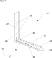
- Fig. 1 shows a simplified schematic representation of an L-shaped bracket (10) for a cavity barrier according to an embodiment.
- L-shaped bracket (10) for a cavity barrier has a vertical section (20) and a horizontal section (30).
- the vertical section (20) is for fixing to a substrate, preferably an exterior wall surface.
- the horizontal section (30) is for inserting into the cavity barrier.
- the horizontal section (30) comprises at least one tab (40) extending out in a vertical direction relative to the horizontal section (30).
- vertical direction relates to up or down relative to a horizonal plane, in present case the horizontal section (30).
- the at least one tab (40) is stamped out and bent out of the horizontal section (30) at an angle. It is preferred that the at least one tab (40) is bent out of the horizontal section (30) at less than 90 degrees, preferably less than 45 degrees, measured from the horizontal section (30) in the direction of the bend. It is particularly preferred that the direction of the at least one tab (40), preferably two tabs (40), extending out of the horizontal section (30) produces a harpoon type arrangement, such that the at least one tab (40), preferably two tabs (40), extends out and bends out from the horizonal section (30) in the opposite direction from the insertion direction, i.e. the direction the horizontal section (30) is inserted into the cavity barrier. It is preferred that the at least one tab (40) is bent out of the horizonal section at an angle, wherein the angle is open in the direction opposite of the insertion direction.
- the horizontal section (30) of the L-shaped bracket (10) comprises two tabs (40).
- the two tabs (40) extend out of the horizontal section (30) in the vertical direction in the opposite directions relative to the horizonal section (30). This means that the first tab (40) is bent into the horizontal section (30), and the other, second tab (40), is bend out of the horizontal section (30), relative to the first tap (40).
- the tab (40) closest to the end (50) of the horizontal section (30) extends up, and the tab (40) closest to the inside corner, where the horizonal section (30) meets the vertical section (20) of the L-shaped bracket (10), extends down, wherein the two tabs (40) are extended out of the horizontal section (30) in the opposite direction of each other.
- the shape of the tabs (40) is isosceles trapezoid, wherein out of the two parallel sides, the narrower side is the one that stays attached to the horizontal section (30) of the L-shaped bracket and the wider parallel side of the isosceles trapezoid is the one that is bent out of the horizontal section (30), either in the upward or the downward direction relative to the horizontal section (30) of the L-shaped bracket (10).
- the vertical section (20) of the L-shaped bracket (10) comprises at least one opening (70), preferably two openings (70), intended for fastening means.
- the openings (70) are preferred to be of a round shape. It is possible to also use direct fastening above, between and below the two openings (70). It is not necessary for the vertical section (20) to have any openings (70), such that the L-shaped bracket (10) can be fastened using direct fastening.
- the end (50) of the horizontal section (30) is sloped into a point, which has a triangular shape and an acute angular pointed end.
- the horizontal section (30) and/or the vertical section (20) of the L-shaped bracket (10) comprises at least one rib (80) running along in the direction of the horizontal section (30) and/or vertical section (20) of the L-shaped bracket (10). It is preferred that the majority of the at least one rib (80), preferably at least 60 % based on the entire length of the rib (80) is on the horizontal section (30) of the L-shaped bracket (10).
- the rib (80) runs continuously starting at about the middle or less of the vertical section (20), measured from the inner angle of the L-shaped bracket (10), to the middle or less of the horizontal section (30), measured from the inner angle of the L-shaped bracket (10). It is preferred that the at least one rib (80) does not go through any tabs (40) or any openings (70).
- At least one edge (60) of the horizontal section (30) in the longitudinal direction and/or at least one edge (60) of the vertical section (20) in the longitudinal direction are flipped inward (i.e. towards the inside of the L-shaped bracket) into a U-shape at about 90 degrees measured from the horizontal section (30) and/or from the vertical section (20).
- both edges (60) of the horizontal section (30) in the longitudinal direction and both edges (60) of the vertical section (20) in the longitudinal direction are flipped inward towards the inside of the L-shaped bracket into a U-shape at about 90 degrees measured from the horizonal section (30) and vertical section (20).
- Figures 2 shows the L-shaped bracket of the present invention in a rotated orientation so that the bottom of horizontal section may be viewed.
- Figure 2 shows the that the at least one flipped edge (60) of the horizontal section (30) comprises at least one protruding element (60a), preferably 2 to 10 protruding elements (60a), extending out of the flipped edge (60).
- the at least one protruding element (60a), preferably 2 to 10 protruding elements, can extend out in the horizontal direction and/or vertical direction from the at least one flipped edge (60) of the horizontal section (30).
- the at least one protruding element (60a), preferably 2 to 10 protruding elements (60a), is arranged on the horizontal section (30) between the inside of the L-shaped bracket until about the middle of the horizontal section (30) of the L-shaped bracket (10), preferably three quarters toward the middle of the horizontal section (30) of the L-shaped bracket (10). It is preferred that 2 to 10 protruding elements (60a), form a zig-zag toothed surface.
- the at least one flipped edge (60) of the horizontal section (30) is wider in the vertical direction towards the inside of the L-shaped bracket (10) in relation to the flipped edge (60) of the horizontal section (30) towards the end (50) of the horizontal section (30). It is preferred that the at least one flipped edge (60) of the horizontal section is narrower in the vertical direction towards the end (50) of the L-shaped bracket in relation to the flipped edge (60) of the horizontal section (30) towards the inside of the L-shaped bracket. This difference creates a slope, wherein the horizontal section (30) is wider in the vertical direction towards the inside of the L-shaped bracket compared to the end (50) of the horizontal section (30) of the L-shaped bracket (10). Having a wider flipped edge (60) in the vertical direction towards the inside of the L-shaped bracket allows the flipped edge (50) to rest on the surface of the wall, providing extra support and stability to the L-shaped bracket (10) to hold the cavity barrier.
- At least a portion of the at least one flipped edge (60) of the horizontal section (30) in the longitudinal direction is flipped a second time at about 90 degrees in the same direction of the first flip, preferably creating an open hem (60d) that has edges of bending that are about 90 degrees.
- both edges (60) of the horizontal section (30) in the longitudinal direction are flipped downward away from the inside of the L-shaped bracket (10) at about 90 degrees measured from the horizontal section (30).
- both edges (60), preferably the entire length of the edges (60), of the horizontal section (30) in the longitudinal direction are flipped a second time at about 90 degrees in the same direction of the first flip creating a simiclosed or closed volume (60b). It is preferred that both edges (60) of the horizontal section (30) in the longitudinal direction are flipped a second time at about 90 degrees in the same direction of the first flip creating a simiclosed or closed volume (60b) starting at about the middle of the horizontal section (30) and ending towards the end (50) of the horizontal section (30).
- the flipped twice edge (60) of the horizontal section (30) creates a closed hem (60c) towards the end (50) of the horizontal section (30), and have an open hem (60d), having edges of bending that are about 90 degrees, towards the inside of the L-shaped bracket of the horizontal section (30), preferably the middle of the horizonal section (30). It is preferred that the folded twice edges (60) of the horizontal section (30) create a volume (60b), more preferably towards the end (50) of the horizontal section (30).
- the L-shaped bracket (10) can be made of a single piece of metal, such as stainless steel, galvanized steel, or aluminum alloy.
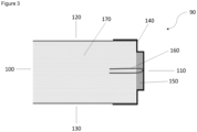
- Fig. 3 shows a simplified schematic representation of a cavity barrier according to one embodiment.
- the Present invention further relates to an air gap shield system comprising the L-shaped bracket (10) according to any one of embodiments disclosed herein and a cavity barrier (90) as shown in Figure 2 .
- the cavity barrier (90) has a base body (170) with an insertion surface (100) for inserting the L-shaped bracket (10), a front surface (110) which is opposite of the insertion surface (110), a top surface (120) and a bottom surface (130) being opposite the top surface (120).
- the base body (170) can be made of mineral wool, such as rock and/or basalt based mineral wool.
- the base body can be covered with a foil. It is preferred that the insertion surface (100) of the base body (90) is not covered with a foil. It is also preferred that the front surface (110) of the base body (90) is also not covered with a foil. It is preferred that the top surface (120) and the bottom surface (130) of the base body (90) are covered with a foil, wherein the foil is an aluminum foil reinforced with glass fiber mesh.
- the front surface (110) of the base body (90) is covered with a front side layer (140).
- the front side layer (140) also covers at least a portion of the top surface (120) and/or at least a portion of the bottom surface (130).
- the front side layer (140) is one continuous piece of material.
- the front side layer (140) is made of polyethylene foil, polypropylene foil, aluminum foil, glass mesh, metal wire mesh, plastic mesh or combinations of two or more thereof. It is particularly preferred that the front side layer is a composite foil made of three layers: metal foil layer (e.g. aluminum foil), mesh layer (e.g. glass fiber mesh or plastic fiber mesh) and polyethylene foil or polypropylene foil. It is particularly preferred that the front side layer is a composite polyethylene foil reinforced with glass fiber mesh.
- the front side layer (140) is attached to the base body (170) with chemical means, preferably an adhesive, more preferably a hot melt adhesive.
- a ventilated barrier in a ventilated façade it is preferred that there is at least one strip of intumescent material (150), preferably there are 2 or 3 strips of intumescent material (150), positioned between the front side layer (140) and the front surface (110) of the base body (170). It is also possible that a cavity barrier (90) does not comprise at least one strip of intumescent material (150) and can be used as a non-ventilated barrier in ventilated façades.
- the at least one strip of intumescent material (150) is preferably expandable graphite based intumescent material.
- the at least one strip of intumescent material (150) has a foil covering. It is preferred that the foil covering is a composite foil comprising polyethylene foil and glass fiber mesh.
- the at least one strip of intumescent material (150) comprises at least one staple (160) that attaches the at least one strip of intumescent material (150) to the front surface (110) of the base body (170).
- the at least one strip of intumescent material (150) is attached to the front surface (110) of the base body (170) using chemical means, such as an adhesive, preferably a hot melt adhesive.
- the at least one strip of intumescent material (150) that is directly adjacent to the front side layer (140) comprises at least one staple (160), preferably 2 to 16 staples (160).
- the at least one staple (160) is a U-shaped staple made of metal or plastic.
- Present invention also relates to a building construction comprising a ventilated façade defined by an exterior wall surface, at least one bracket for fastening at least one façade panel to the exterior wall surface, at least one insulation layer attached to the exterior wall surface and supported by the at least one bracket, and an air gap between the at least one insulation layer and the at least one façade panel, wherein the air gap is closed with an air gap shield system according to the present invention comprising an L-shaped bracket (10) and a cavity barrier (90), wherein the L-shaped bracket (10) has a vertical section (20) and a horizontal section (30), wherein the vertical section (20) is for fixing to the exterior wall surface, wherein the horizontal section (30) is for inserting into the cavity barrier (90), wherein the horizontal section (30) comprises at least one tab (40) extending out in a vertical direction relative to the horizontal section (30) and/or wherein at least one edge (60) of the horizontal section (30) in the longitudinal direction is flipped downward away from the inside of the L-shaped bracket at about 90 degrees measured from the horizontal section (30), wherein
Landscapes
- Engineering & Computer Science (AREA)
- Architecture (AREA)
- Civil Engineering (AREA)
- Structural Engineering (AREA)
- Physics & Mathematics (AREA)
- Electromagnetism (AREA)
- Building Environments (AREA)
- Finishing Walls (AREA)
Abstract
The invention relates to an L-shaped bracket for a cavity barrier, an air gap shield system, and the use thereof for closing a cavity to improve fire protection of a ventilated façade. Present invention also relates a building construction comprising the air gap shield system.
Description
- The invention relates to an L-shaped bracket for a cavity barrier, an air gap shield system, and the use thereof for closing a cavity to improve fire protection of a ventilated façade. Present invention also relates a building construction comprising the air gap shield system.
- Ventilated façades require cavity barriers, such as ventilated and non-ventilated barriers, that would, in case of a fire, prevent the fire moving from bottom of the façade to the top. For example, in case of a broken window, the fire can spread over the air gap between the insulation layer and the cladding of the façade and move upwards.
- Some countries, such as Great Britain, require that such cavity barriers would stop the fire spread within 5 min and pass the TGD 19 test standard. Higher standards of fire protection for ventilated façades are becoming a priority for many countries around the worlds. Thus, there is an increasing need for improved cavity barrier systems that can pass different test standards around the world.
- Standard method of installing a cavity barrier requires a bracket. Most brackets on the market require shaping/bending and producing the desired L-shape of the bracket on site. In some cases, there is also a need to attach the intumescent material to the cavity barrier in a separate step. Many cavity barrier systems known in the art also are limited to a certain size of the air gap, such as air gap of 25 mm or less. This is usually limited by the bracket, which cannot support larger sizes of cavity barriers.
- There are two main methods uses in the art, both of which are very time consuming and need mechanical fixing and/or compression. In the first typical method, generally a bracket must be pushed through the intumescent strip to fix the intumescent strip together with the barrier to the wall, such as butterfly bending of the bracket. The disadvantage of such method is that the full shielding function of the cavity barrier is not possible because the intumescent material would not be able to fully expand in the area of the bracket fixation. In the second method, generally the bracket goes into the mineral wool part of the barrier only and the intumescent strip must be attached to the mineral wool of the barrier in a separate step using fixation such as a spring like screws. In turn, the cladding panel is then able to keep the barrier in the intended position.
- In the second method where the bracket is pushed into the cavity barrier only, there is no protection against the cavity barrier moving away from the surface of the wall. The cavity barrier may start slipping off the smooth bracket, which itself may also start to droop. Especially, in the event of construction stop (for 3 to 6 months), this may become a critical issue, since the cavity barrier can be exposed to weather conditions, such as rain, wind, and thunderstorms.
- Thus, there is a need for a new bracket or a bracket and barrier solution that would be faster and easier to install, having improved stability that shows resistance to weather exposure, such as rain, wind and storms, of up to 6 months, having long term fixation of the intumescent strip to the cavity barrier, while at the same time providing a functional fire solution in a ventilated fagade having an air gap between the insulation layer and the cladding of 25 mm or greater.
- Therefore, the object of the present invention is to provide a bracket or a bracket and a cavity barrier solution that solves the problems existing the art as outlined above, such as solving the problem of time consuming preinstallation and installation methods, poor stability of the bracket, fixation of the intumescent strip to the cavity barrier, and limited application in view of the size of the air gap between the insulation layer and the cladding.
- Present invention relates to an L-shaped bracket for a cavity barrier that can be used in a ventilated façade. The L-shaped bracket according to the present invention has a vertical section and a horizontal section. According to the present invention the vertical section is intended for fixing to a substrate, such as an exterior wall surface. It is also preferred that the L-shaped bracket according to the present invention is used for fixing to an interior wall surface. The horizontal section of the L-shaped bracket is used for inserting into the cavity barrier. The horizontal section of the L-shaped bracket comprises at least one tab extending out in a vertical direction relative to the horizontal section and/or wherein at least one edge of the horizontal section in the longitudinal direction is flipped downward away from the inside of the L-shaped bracket at about 90 degrees measured from the horizontal section, wherein the at least one flipped edge of the horizontal section is wider in the vertical direction towards the inside of the L-shaped bracket in relation to the flipped edge of the horizontal section towards the end of the horizontal section.
- It is understood that vertical direction relates to up or down relative to a horizonal plane, in present case the horizontal section. The at least one tab serves the purpose of securing the cavity barrier on the L-shaped bracket of the present invention. Thus, the cavity barrier would not be able to slip off the L-shaped bracket after a prolonged period of time, such as in case of construction stop or harsh weather conditions, such as rain, wind and thunderstorms. The at least one flipped edge of the horizontal section aids in the stability of the L-shaped bracket. It is preferred that the length of the vertical section ranges from 80 to 200 mm, more preferably 100 to 160 mm. It is preferred that the length of the horizontal section ranges from 80 to 500 mm, more preferably from 100 to 400 mm, more preferably from 110 to 300 mm. It is preferred that the L-shaped bracket for a cavity barrier would be suitable and have the required fire stop performance for air gaps in ventilated façades that are less than 25 mm, more preferably greater than or equal to 25 mm, more preferably greater than 35 mm, more preferably greater than or equal to 50 mm, more preferably greater than 55 mm. It is preferred that the L-shaped bracket for a cavity barrier would be suitable and have the required fire stop performance for air gaps in ventilated façades in the range of from 25 mm to 55 mm, more preferably in the range of from 35 mm to 50 mm.
- It is preferred that the at least one tab is stamped out and bent out of the horizontal section at an angle. It is preferred that the at least one tab is bent out of the horizontal section at less than 90 degrees, preferably less than 45 degrees, measured from the horizontal section in the direction of the bend. It is preferred that the at least one tab is manufactured by a sheet metal stamping process using a progressive die set. In such a process, it is typical that first slots are blanked in the metal strip (e.g. horizontal section) and then the tab geometry is cut and the tabs are bent into their final positions angled relative to the plane of the metal strip. It is particularly preferred that the direction of the at least one tab, preferably two tabs, extending out of the horizontal section produces a harpoon type arrangement, such that the at least one tab, preferably two tabs, extends out and bends out from the horizonal section in the opposite direction from the insertion direction, i.e. the direction the horizontal section is inserted into the cavity barrier. It is preferred that the at least one tab is bent out of the horizonal section at an angle, wherein the angle is open in the direction opposite of the insertion direction. Such harpoon type arrangement of at least one tab, preferably two tabs, on the horizontal section of the L-shaped bracket allows for a better securing of the cavity barrier. Specifically, the material of the cavity barrier, such as mineral wool, gets caught on the harpoon type arrangement of the at least one tab which does not allow the cavity barrier to slip off the L-shaped bracket.
- It is particularly preferred that the horizontal section of the L-shaped bracket comprises two tabs.
- In case the horizontal section of the L-shaped bracket comprises two tabs, it is preferred that the two tabs extend out of the horizontal section in the vertical direction in the opposite directions relative to the horizonal section. This means that the first tab is bent into the horizontal section, and the other, second tab, is bend out of the horizontal section, relative to the first tap. It is preferred that the tab closest to the end of the horizontal section extends up or down relative to the horizontal section, and the tab closest to the inside corner, where the horizonal section meets the vertical section of the L-shaped bracket, extends up or down relative to the horizontal section, wherein the two tabs are extended out of the horizontal section in the opposite direction of each other relative to the horizontal section. It is particularly preferred that the direction of the two tabs extending out of the horizontal section produces a harpoon type arrangement, such that the two tabs, extend out and bend out from the horizonal section in the opposite direction of the insertion direction, i.e. the direction of the insertion into the cavity barrier. Having the tabs bend out in a harpoon type arrangement and in the opposite directions from each other relative to the horizontal section would further promote the secure fixing of the cavity barrier on the L-shaped bracket according to the present invention. In another embodiment, it is preferred that the horizontal section of the L-shaped bracket comprises 3 to 8 tabs. In case where there are more than two tabs present on the horizontal section, it is preferred that the tabs are bent out of the horizontal section in alternating directions of up and down relative to each other as described herewith. In case where there are more than two tabs present on the horizontal section, it is preferred that the tabs are bend out in a harpoon type arrangement as outlined herewith.
- It is preferred that the shape of the stamped tab is trapezoidal, preferably isosceles trapezoid, wherein out of the two parallel sides, the narrower side is the one that stays attached to the horizontal section of the L-shaped bracket and the wider parallel side of the isosceles trapezoid is the one that is bent out of the horizontal section, either in the upward or the downward direction relative to the horizontal section of the L-shaped bracket. Present invention is not limited to a single shape of the at least one tab and it is possible to use any conceivable shape of the at least one tab, such as square, rectangular, triangular, semicircular, semioval or irregular shape.
- It is preferred that the vertical section of the L-shaped bracket comprises at least one opening, preferably two openings, more preferably three or four openings, intended for fastening means. It is preferred that the openings are of a circular shape, but can be of any other shape as well, such as square, rectangular, triangular, trapezoidal or other suitable geometric shapes. Said at least one opening is suitable for fastening means such as screws and/or anchors. It is preferred that there are at least two openings on the vertical section of the L-shaped bracket. In another embodiment, it is preferred that the vertical section does not comprise any openings intended for fastening means, such that the L-shaped bracket of the present invention can be attached to the substrate or a wall using direct fastening means only. Thus, the vertical section of the L-shaped bracket is suitable to be fastened directly to a substrate or a wall, allowing more flexibility for a skilled worker to be able to decide the exact position of the vertical section that should be fastened to a substrate or a wall, which is not predetermined with an opening. In yet another embodiment, in case where the vertical section of the L-shaped bracket comprises two openings, it is preferred that said openings are arranged in such a way that there is enough space to directly fasten either between, above or below the two openings. Same would apply if there was only one opening on the vertical section of the L-shaped bracket, such that it would be possible to use direct fastening either above or below the only opening on the vertical section of the L-shaped bracket.
- It is preferred that the L-shaped bracket it attached to a surface in its intended "L" shape. In another embodiment it is preferred that the bracket is installed in the sideway shape of "L", where the horizontal section is above the vertical section.
- It is preferred that the end of the horizontal section is sloped into a point. It is preferred that the end of the horizontal section has a triangular shape, having an acute angular pointed end. Thus, the pointed end of the horizontal section would allow for an easier insertion into the cavity barrier. This would allow for a more seamless and easy installation of the cavity barrier onto the L-shaped bracket, and thus onto the substrate or a wall. In another embodiment, it is preferred that the horizontal section has a blunt rectangular end. It is also preferred that the horizontal section narrows into a rounded or blunt rectangular end. It is also preferred that the end of the horizontal section has a toothed end, comprising at least two pointed teeth.
- It is preferred that the horizontal section and/or the vertical section of the L-shaped bracket comprises at least one rib, alternatively 2 or 3 ribs, running along in the direction of the horizontal section and/or vertical section of the L-shaped bracket. It is preferred that the at least one rib is punched out in the direction away from the inner corner of the L-shaped bracket. In another embodiment it is preferred that the rib is punched out in the direction toward the inner corner of the L-shaped bracket. It is preferred that the at least one rib runs in the middle of the horizontal section and/or of the vertical section. It is also preferred that the majority of the at least one rib, preferably at least 60 % based on the entire length of the rib is on the horizontal section of the L-shaped bracket. It is preferred that the at least one rib runs continuously starting at about the middle or less of the vertical section, measured from the inner angle of the L-shaped bracket, to the middle or less of the horizontal section, measured from the inner angle of the L-shaped bracket. The at least one rib of any one of the embodiments as disclosed herewith provides extra stability to the L-shaped bracket, allowing it to maintain its right-angled shape and not droop, especially in harsh weather conditions, such as rain, wind, and thunderstorms. The stability added by the at least one rib allows the L-shaped bracket to have a better performance over a longer period of time than the brackets and air gap shield systems that are currently on the market. It is preferred that the at least one rib runs continuously and is not interrupted by at least one tab and at least one opening. Thus, it is preferred that the at least one rib does not go through any tabs or any openings. In another embodiment it is preferred that the at least one rib goes through at least one tab and/or at least one opening.
- It is preferred that the at least one flipped edge of the horizontal section comprises at least one protruding element, preferably 2 to 10 protruding elements, extending out of the flipped edge. The at least one protruding element, preferably 2 to 10 protruding elements, can extend out in the horizontal direction and/or vertical direction from the at least one flipped edge of the horizontal section. It is preferred that the at least one protruding element, preferably 2 to 10 protruding elements, is arranged on the horizontal section between the inside of the L-shaped bracket until about the middle of the horizontal section of the L-shaped bracket, preferably three quarters toward the middle of the horizontal section of the L-shaped bracket. It is preferred that the at least one protruding element, preferably 2 to 10 protruding elements, form a zig-zag toothed surface. The zig-zagged toothed surface can be any imaginable organization of the protruding elements, having the same or different sizes and/or shapes. The at least one protruding element will allow the horizontal section to hold on to the cavity barrier and prevent it from slipping or sliding off.
- According to the present invention the at least one flipped edge of the horizontal section is wider in the vertical direction towards the inside of the L-shaped bracket in relation to the flipped edge of the horizontal section towards the end of the horizontal section. It is preferred that the at least one flipped edge of the horizontal section is narrower in the vertical direction towards the end of the L-shaped bracket in relation to the flipped edge of the horizontal section towards the inside of the L-shaped bracket. This difference creates a slope, wherein the horizontal section is wider in the vertical direction towards the inside of the L-shaped bracket compared to the end of the horizontal section of the L-shaped bracket. Having a wider flipped edge in the vertical direction towards the inside of the L-shaped bracket allows the flipped edge to rest on the surface of the wall, providing extra support and stability to the L-shaped bracket for it to hold the cavity barrier.
- It is preferred that at least a portion of the at least one flipped edge of the horizontal section in the longitudinal direction is flipped a second time at about 90 degrees in the same direction of the first flip, preferably creating an open hem that has edges of bending that are about 90 degrees.
- It is preferred that both edges of the horizontal section in the longitudinal direction are flipped downward away from the inside of the L-shaped bracket at about 90 degrees measured from the horizontal section.
- It is preferred that at least a portion of both edges, preferably the entire length of the edges, of the horizontal section in the longitudinal direction are flipped a second time at about 90 degrees in the same direction of the first flip creating a semiclosed or closed volume. It is preferred that both edges of the horizontal section in the longitudinal direction are flipped a second time at about 90 degrees in the same direction of the first flip creating a semiclosed or closed volume starting at about the middle of the horizontal section and ending towards the end of the horizontal section. It is preferred that the flipped twice edge of the horizontal section creates a closed hem towards the end of the horizontal section, and have an open hem, having edges of bending that are about 90 degrees, towards the inside of the L-shaped bracket of the horizontal section, preferably the middle of the horizonal section. It is preferred that the folded twice edges of the horizontal section create a volume, more preferably towards the end of the horizontal section, that assists in the compression of the cavity barrier, thus preventing the cavity barrier from slipping off the horizontal section of the L-shaped bracket. In another embodiment, it is also preferred that at least one edge of the horizontal section in the longitudinal direction and/or at least one edge of the vertical section in the longitudinal direction are flipped inward (i.e. towards the inside of the L-shaped bracket) into a U-shape at about 90 degrees measured from the horizontal section and/or from the vertical section. It was found that the at least one flipped inward edge of the horizontal and/or vertical section give even more stability to the L-shaped bracket, allowing it to perform and keep its shape for a longer period of time and under harsh weather conditions, such as rain, wind and thunderstorms. It is preferred that both edges of the horizontal section in the longitudinal direction and both edges of the vertical section in the longitudinal direction are flipped inward towards the inside of the L-shaped bracket into a U-shape at about 90 degrees measured from the horizonal and vertical section. It is preferred that the width of the flipped edges is the same width along the horizonal section and/or vertical section. In another embodiment, it is preferred that the at least one edge of the horizontal and/or vertical section, preferably both edges of the horizontal section in the longitudinal direction and both edges of the vertical section in the longitudinal direction, as disclosed herewith are flipped at about 90 degrees away from the inside of the L-shaped bracket. It is preferred that the width of the flipped edges away from the inside of the L-shaped bracket is the same width along the horizonal section and/or vertical section.
- According to the present invention the horizontal section of the L-shaped bracket has a thickness in the vertical direction.
- According to the present invention the vertical section of the L-shaped bracket has a thickness in the horizontal direction.
- It is preferred that the L-shaped bracket is made of a single piece of metal (i.e. sheet of metal), preferably stainless steel, galvanized steel or aluminum alloy. It is preferred that the thickness of the piece of metal is the same throughout. In another embodiment, it is preferred that the piece of metal is thicker where the bend of the L-shape is installed for improving stability of the L-shaped bracket.
- Present invention further relates to an air gap shield system comprising the L-shaped bracket according to any one of embodiments disclosed herein and a cavity barrier for ventilated façades. The cavity barrier has a base body with an insertion surface for inserting the L-shaped bracket, a front surface which is opposite of the insertion surface, a top surface and a bottom surface being opposite the top surface.
- It is preferred that the base body is made of mineral wool, such as rock and/or basalt based mineral wool.
- Materials such as mineral wool are well known in the art for the use as insulation or part of fire protection technology.
- It is preferred that for easier handling the base body is covered with a foil. It is preferred that the insertion surface of the base body is not covered with a foil. Having exposed base body at the insertion surface, such as exposed mineral wool that is not covered with a foil, allows for an easier insertion with the vertical section of the L-shaped bracket. It is also preferred that the front surface of the base body is also not covered with a foil. It is preferred that the top surface and bottom surface of the base body are covered with a foil, wherein the foil is an aluminum foil reinforced with glass fiber mesh.
- It is preferred that at least a portion of the front surface of the base body is covered with a front side layer, preferably wherein the front side layer also covers at least a portion of the top surface and/or at least a portion of the bottom surface. It is preferred that the front side layer is one continuous piece of material.
- It is preferred that the front side layer is made of polyethylene foil, polypropylene foil, aluminum foil, glass mesh, metal wire mesh, plastic mesh or combinations of two or more thereof. It is particularly preferred that the front side layer is a composite foil made of three layers: metal foil layer (e.g. aluminum foil), mesh layer (e.g. glass fiber mesh or plastic fiber mesh) and polyethylene foil or polypropylene foil. It is particularly preferred that the front side layer is a composite polyethylene foil reinforced with glass fiber mesh. The front side layer provides improved mechanical stability to the cavity barrier during a fire, such that the mesh comprised in the front side layer would further assist in holding the expanded intumescent material in place.
- The front side layer protects the base body, and preferably at least one strip of intumescent material, and holds the cavity barrier together.
- Aluminum foil or a composite foil as disclosed herewith, when used as the front side layer, works like a shield, and stops the airflow. In case there is at least one intumescent strip present between the front surface and the front side layer (e.g. aluminum foil or a composite foil), the at least one intumescent strip would get more energy/heat, thus, also start the intumescent reaction earlier and faster compared to standard combustible foils, such as polyethylene or polypropylene foils.
- It is preferred that the front side layer is attached to the base body with an adhesive, preferably hot melt adhesive. In case of fire, the hotmelt between the front side layer and the base body would liquify and loosen the adhesion at the area where the heat was applied on the front side layer. If other types of adhesives are used, such as based on acrylics, epoxy, etc., the adhesive would typically burn off and away, thus loosening of the adhesion at the area where the heat was applied on the front side layer. Once the adhesion is loosened the front side layer can open at the side of the fire and the at least one intumescent strip would come in contact with the hot gasses and start the intumescent reaction expanding and closing the cavity/air gap.
- It is preferred that the front side layer is attached to the base body with chemical means, such as an adhesive, and/or mechanical means, such as a staple, a pin, a screw, pigtail screw, a nail and combinations of two or more thereof. It is preferred that the front side layer is attached to the base body with an adhesive, preferably a hot melt adhesive. It is also preferred that the front side layer is attached to the base body with a chemical adhesive selected from the group comprising methacrylates, acrylics, epoxy, cyanoacrylate adhesives and combinations of two or more thereof.
- It is preferred that there is at least one strip of intumescent material, preferably there are 2, 3, 4, 5, or 6 strips of intumescent material, positioned between the front side layer and the front surface of the base body. It is preferred that a cavity barrier that comprises at least one strip of intumescent material is used as a ventilated barrier for a ventilated façade. It is also preferred that a cavity barrier that does not comprise at least one strip of intumescent material is used as a non-ventilated barrier in ventilated façades.
- It is preferred that the at least one strip of intumescent material is expandable graphite based intumescent material.
- It is also preferred that the at least one strip of intumescent material has a foil covering. The foil covering provides easy handling of the intumescent material. It is preferred that the foil covering is a composite foil comprising polyethylene foil and glass fiber mesh.
- It is preferred that the at least one strip of intumescent material comprises at least one mechanical means of attachment that attaches the at least one strip of intumescent material to the front surface of the base body. Any conceivable mechanical means of attachment may be used for attaching at least one strip of intumescent material to the front surface of the base body, such as pins, screws, nails and staples. It is preferred that at least one staple can be used for attaching the at least one strip of intumescent material to the front surface of the base body. It is preferred that the at least one staple has a U-shape. In another embodiment it is preferred that at least one pin, preferably a T-shaped pin, is used instead of at least one staple in any of the embodiments as disclosed herein.
- In another embodiment it is preferred that the at least one strip of intumescent material is attached to the front surface of the base body using chemical means, such as an adhesive, preferably a hot melt adhesive.
- It is preferred that the at least one strip of intumescent material that is directly adjacent to the front side layer comprises at least one staple, preferably 2 to 16 staples.
- It is preferred that the at least one staple is a U-shaped staple made of metal or plastic.
- It is preferred that the at least one staple, or at least one pin is installed into the at least one strip of intumescent material to attach it into the front surface of the base body before the front side layer is applied to the base body. It is also preferred that the at least one strip of intumescent material directly adjacent to the front side layer comprises at least one staple or a pin, that would go through and attach any additional strips of intumescent material, that are between the front surface of the base body and the strip of intumescent material directly adjacent, to the front side layer. In another embodiment it is possible to attach the at least one strip of intumescent material to the front surface of the base body with at least one staple, or at least one pin after the front side layer is applied. In one embodiment it is preferred that the cavity barrier does not comprise a front side layer and the at least one strip of intumescent material is attached to the front surface of the base body with mechanical means, such as at least one staple and/or at least one pin and/or with chemical means, such as an adhesive, preferably a hot melt adhesive.
- There is no restriction to the location of attachment for the mechanical means for the at least one strip of intumescent material. It is preferred that at least one staple, preferably 2 to 16 staples, are installed in the middle and/or on the top end and/or on the bottom end of the at least one strip of intumescent material.
- Present invention also relates to a use of the air gap shield system according to any of embodiments disclosed herein to close an air gap cavity in a ventilated façade and improve the fire protection thereof.
- Present invention also relates to a building construction comprising a ventilated façade defined by an exterior wall surface, at least one bracket for fastening at least one façade panel to the exterior wall surface, at least one insulation layer attached to the exterior wall surface and supported by the at least one bracket, and an air gap between the at least one insulation layer and the at least one façade panel, wherein the air gap is closed with an air gap shield system comprising an L-shaped bracket and a cavity barrier for closing the air gap of a ventilated façade, wherein the L-shaped bracket has a vertical section and a horizontal section, wherein the vertical section is for fixing to the exterior wall surface, wherein the horizontal section is for inserting into the cavity barrier, wherein the horizontal section comprises at least one tab extending out in a vertical direction relative to the horizontal section, wherein the cavity barrier is for creating a barrier in the air gap of a ventilated façade, wherein the cavity barrier has a base body with an insertion surface for inserting the L-shaped bracket, a front surface which is opposite of the insertion surface, a top surface and a bottom surface being opposite the top surface.
- The invention and further advantageous embodiments and developments thereof are described and explained in more detail below with reference to the examples shown in the drawings. The features found in the description and the drawings can be applied individually or together in any combination according to the invention. In the drawings:
- -
Fig. 1 shows a simplified schematic representation of an L-shaped bracket for a cavity barrier according to an embodiment, - -
Fig. 2 shows a simplifies schematic representation of an L-shaped bracket for a cavity barrier according to an embodiment, and - -
Fig. 3 shows a simplified schematic representation of a cavity barrier according to one embodiment, - All features disclosed below with respect to the exemplary embodiments and/or accompanying figures can be combined, alone or in any sub-combination, with features of the aspects of the present disclosure, including features of preferred embodiments, provided that the resulting feature combination is useful to a person skilled in the art in the field of technology.
-
Fig. 1 shows a simplified schematic representation of an L-shaped bracket (10) for a cavity barrier according to an embodiment. - L-shaped bracket (10) for a cavity barrier, has a vertical section (20) and a horizontal section (30). The vertical section (20) is for fixing to a substrate, preferably an exterior wall surface. The horizontal section (30) is for inserting into the cavity barrier. The horizontal section (30) comprises at least one tab (40) extending out in a vertical direction relative to the horizontal section (30).
- It is understood that vertical direction relates to up or down relative to a horizonal plane, in present case the horizontal section (30).
- The at least one tab (40) is stamped out and bent out of the horizontal section (30) at an angle. It is preferred that the at least one tab (40) is bent out of the horizontal section (30) at less than 90 degrees, preferably less than 45 degrees, measured from the horizontal section (30) in the direction of the bend. It is particularly preferred that the direction of the at least one tab (40), preferably two tabs (40), extending out of the horizontal section (30) produces a harpoon type arrangement, such that the at least one tab (40), preferably two tabs (40), extends out and bends out from the horizonal section (30) in the opposite direction from the insertion direction, i.e. the direction the horizontal section (30) is inserted into the cavity barrier. It is preferred that the at least one tab (40) is bent out of the horizonal section at an angle, wherein the angle is open in the direction opposite of the insertion direction.
- It is particularly preferred that the horizontal section (30) of the L-shaped bracket (10) comprises two tabs (40). The two tabs (40) extend out of the horizontal section (30) in the vertical direction in the opposite directions relative to the horizonal section (30). This means that the first tab (40) is bent into the horizontal section (30), and the other, second tab (40), is bend out of the horizontal section (30), relative to the first tap (40). In
Fig. 1 the tab (40) closest to the end (50) of the horizontal section (30) extends up, and the tab (40) closest to the inside corner, where the horizonal section (30) meets the vertical section (20) of the L-shaped bracket (10), extends down, wherein the two tabs (40) are extended out of the horizontal section (30) in the opposite direction of each other. - The shape of the tabs (40) is isosceles trapezoid, wherein out of the two parallel sides, the narrower side is the one that stays attached to the horizontal section (30) of the L-shaped bracket and the wider parallel side of the isosceles trapezoid is the one that is bent out of the horizontal section (30), either in the upward or the downward direction relative to the horizontal section (30) of the L-shaped bracket (10).
- The vertical section (20) of the L-shaped bracket (10) comprises at least one opening (70), preferably two openings (70), intended for fastening means. The openings (70) are preferred to be of a round shape. It is possible to also use direct fastening above, between and below the two openings (70). It is not necessary for the vertical section (20) to have any openings (70), such that the L-shaped bracket (10) can be fastened using direct fastening.
- The end (50) of the horizontal section (30) is sloped into a point, which has a triangular shape and an acute angular pointed end.
- The horizontal section (30) and/or the vertical section (20) of the L-shaped bracket (10) comprises at least one rib (80) running along in the direction of the horizontal section (30) and/or vertical section (20) of the L-shaped bracket (10). It is preferred that the majority of the at least one rib (80), preferably at least 60 % based on the entire length of the rib (80) is on the horizontal section (30) of the L-shaped bracket (10). The rib (80) runs continuously starting at about the middle or less of the vertical section (20), measured from the inner angle of the L-shaped bracket (10), to the middle or less of the horizontal section (30), measured from the inner angle of the L-shaped bracket (10). It is preferred that the at least one rib (80) does not go through any tabs (40) or any openings (70).
- It is also preferred that at least one edge (60) of the horizontal section (30) in the longitudinal direction and/or at least one edge (60) of the vertical section (20) in the longitudinal direction are flipped inward (i.e. towards the inside of the L-shaped bracket) into a U-shape at about 90 degrees measured from the horizontal section (30) and/or from the vertical section (20). In
Fig. 1 both edges (60) of the horizontal section (30) in the longitudinal direction and both edges (60) of the vertical section (20) in the longitudinal direction are flipped inward towards the inside of the L-shaped bracket into a U-shape at about 90 degrees measured from the horizonal section (30) and vertical section (20). -
Figures 2 shows the L-shaped bracket of the present invention in a rotated orientation so that the bottom of horizontal section may be viewed.Figure 2 shows the that the at least one flipped edge (60) of the horizontal section (30) comprises at least one protruding element (60a), preferably 2 to 10 protruding elements (60a), extending out of the flipped edge (60). The at least one protruding element (60a), preferably 2 to 10 protruding elements, can extend out in the horizontal direction and/or vertical direction from the at least one flipped edge (60) of the horizontal section (30). It is preferred that the at least one protruding element (60a), preferably 2 to 10 protruding elements (60a), is arranged on the horizontal section (30) between the inside of the L-shaped bracket until about the middle of the horizontal section (30) of the L-shaped bracket (10), preferably three quarters toward the middle of the horizontal section (30) of the L-shaped bracket (10). It is preferred that 2 to 10 protruding elements (60a), form a zig-zag toothed surface. - It is preferred that the at least one flipped edge (60) of the horizontal section (30) is wider in the vertical direction towards the inside of the L-shaped bracket (10) in relation to the flipped edge (60) of the horizontal section (30) towards the end (50) of the horizontal section (30). It is preferred that the at least one flipped edge (60) of the horizontal section is narrower in the vertical direction towards the end (50) of the L-shaped bracket in relation to the flipped edge (60) of the horizontal section (30) towards the inside of the L-shaped bracket. This difference creates a slope, wherein the horizontal section (30) is wider in the vertical direction towards the inside of the L-shaped bracket compared to the end (50) of the horizontal section (30) of the L-shaped bracket (10). Having a wider flipped edge (60) in the vertical direction towards the inside of the L-shaped bracket allows the flipped edge (50) to rest on the surface of the wall, providing extra support and stability to the L-shaped bracket (10) to hold the cavity barrier.
- It is preferred that at least a portion of the at least one flipped edge (60) of the horizontal section (30) in the longitudinal direction is flipped a second time at about 90 degrees in the same direction of the first flip, preferably creating an open hem (60d) that has edges of bending that are about 90 degrees.
- It is preferred that both edges (60) of the horizontal section (30) in the longitudinal direction are flipped downward away from the inside of the L-shaped bracket (10) at about 90 degrees measured from the horizontal section (30).
- It is preferred that at least a portion of both edges (60), preferably the entire length of the edges (60), of the horizontal section (30) in the longitudinal direction are flipped a second time at about 90 degrees in the same direction of the first flip creating a simiclosed or closed volume (60b). It is preferred that both edges (60) of the horizontal section (30) in the longitudinal direction are flipped a second time at about 90 degrees in the same direction of the first flip creating a simiclosed or closed volume (60b) starting at about the middle of the horizontal section (30) and ending towards the end (50) of the horizontal section (30). It is preferred that the flipped twice edge (60) of the horizontal section (30) creates a closed hem (60c) towards the end (50) of the horizontal section (30), and have an open hem (60d), having edges of bending that are about 90 degrees, towards the inside of the L-shaped bracket of the horizontal section (30), preferably the middle of the horizonal section (30). It is preferred that the folded twice edges (60) of the horizontal section (30) create a volume (60b), more preferably towards the end (50) of the horizontal section (30).
- The L-shaped bracket (10) can be made of a single piece of metal, such as stainless steel, galvanized steel, or aluminum alloy.
-
Fig. 3 shows a simplified schematic representation of a cavity barrier according to one embodiment. - Present invention further relates to an air gap shield system comprising the L-shaped bracket (10) according to any one of embodiments disclosed herein and a cavity barrier (90) as shown in
Figure 2 . The cavity barrier (90) has a base body (170) with an insertion surface (100) for inserting the L-shaped bracket (10), a front surface (110) which is opposite of the insertion surface (110), a top surface (120) and a bottom surface (130) being opposite the top surface (120). - The base body (170) can be made of mineral wool, such as rock and/or basalt based mineral wool.
- The base body can be covered with a foil. It is preferred that the insertion surface (100) of the base body (90) is not covered with a foil. It is also preferred that the front surface (110) of the base body (90) is also not covered with a foil. It is preferred that the top surface (120) and the bottom surface (130) of the base body (90) are covered with a foil, wherein the foil is an aluminum foil reinforced with glass fiber mesh.
- The front surface (110) of the base body (90) is covered with a front side layer (140). The front side layer (140) also covers at least a portion of the top surface (120) and/or at least a portion of the bottom surface (130). The front side layer (140) is one continuous piece of material.
- It is preferred that the front side layer (140) is made of polyethylene foil, polypropylene foil, aluminum foil, glass mesh, metal wire mesh, plastic mesh or combinations of two or more thereof. It is particularly preferred that the front side layer is a composite foil made of three layers: metal foil layer (e.g. aluminum foil), mesh layer (e.g. glass fiber mesh or plastic fiber mesh) and polyethylene foil or polypropylene foil. It is particularly preferred that the front side layer is a composite polyethylene foil reinforced with glass fiber mesh.
- It is preferred that the front side layer (140) is attached to the base body (170) with chemical means, preferably an adhesive, more preferably a hot melt adhesive.
- For a ventilated barrier in a ventilated façade, it is preferred that there is at least one strip of intumescent material (150), preferably there are 2 or 3 strips of intumescent material (150), positioned between the front side layer (140) and the front surface (110) of the base body (170). It is also possible that a cavity barrier (90) does not comprise at least one strip of intumescent material (150) and can be used as a non-ventilated barrier in ventilated façades.
- The at least one strip of intumescent material (150) is preferably expandable graphite based intumescent material.
- It is also preferred that the at least one strip of intumescent material (150) has a foil covering. It is preferred that the foil covering is a composite foil comprising polyethylene foil and glass fiber mesh.
- It is preferred that the at least one strip of intumescent material (150) comprises at least one staple (160) that attaches the at least one strip of intumescent material (150) to the front surface (110) of the base body (170).
- In another embodiment it is preferred that the at least one strip of intumescent material (150) is attached to the front surface (110) of the base body (170) using chemical means, such as an adhesive, preferably a hot melt adhesive.
- It is preferred that the at least one strip of intumescent material (150) that is directly adjacent to the front side layer (140) comprises at least one staple (160), preferably 2 to 16 staples (160).
- It is preferred that the at least one staple (160) is a U-shaped staple made of metal or plastic.
- Present invention also relates to a building construction comprising a ventilated façade defined by an exterior wall surface, at least one bracket for fastening at least one façade panel to the exterior wall surface, at least one insulation layer attached to the exterior wall surface and supported by the at least one bracket, and an air gap between the at least one insulation layer and the at least one façade panel, wherein the air gap is closed with an air gap shield system according to the present invention comprising an L-shaped bracket (10) and a cavity barrier (90), wherein the L-shaped bracket (10) has a vertical section (20) and a horizontal section (30), wherein the vertical section (20) is for fixing to the exterior wall surface, wherein the horizontal section (30) is for inserting into the cavity barrier (90), wherein the horizontal section (30) comprises at least one tab (40) extending out in a vertical direction relative to the horizontal section (30) and/or wherein at least one edge (60) of the horizontal section (30) in the longitudinal direction is flipped downward away from the inside of the L-shaped bracket at about 90 degrees measured from the horizontal section (30), wherein the at least one flipped edge (60) of the horizontal section (30) is wider in the vertical direction towards the inside of the L-shaped bracket in relation to the flipped edge (60) of the horizontal section (30) towards the end (50) of the horizontal section (30) , wherein the cavity barrier (90) is for creating a barrier in the air gap of a ventilated façade, wherein the cavity barrier (90) has a base body (170) with an insertion surface (100) for inserting the L-shaped bracket (10), a front surface (110) which is opposite of the insertion surface, a top surface (120) and a bottom surface (130) being opposite the top surface (120).
Claims (17)
- An L-shaped bracket (10) for a cavity barrier, having a vertical section (20) and a horizontal section (30), wherein the vertical section (20) is for fixing to a substrate, preferably an exterior wall surface, wherein the horizontal section (30) is for inserting into the cavity barrier, wherein the horizontal section (30) comprises at least one tab (40) extending out in a vertical direction relative to the horizontal section (30) and/or wherein at least one edge (60) of the horizontal section (30) in the longitudinal direction is flipped downward away from the inside of the L-shaped bracket at about 90 degrees measured from the horizontal section (30), wherein the at least one flipped edge (60) of the horizontal section (30) is wider in the vertical direction towards the inside of the L-shaped bracket in relation to the flipped edge (60) of the horizontal section (30) towards the end (50) of the horizontal section (30).
- The L-shaped bracket (10) according to claim 1, wherein the at least one tab (40) is stamped out and bent out of the horizontal section (30) at an angle.
- The L-shaped bracket (10) according to claim 1 or 2, wherein the horizontal section (30) comprises two tabs (40).
- The L-shaped bracket (10) according to claim 3, wherein the two tabs (40) extend out of the horizontal section (30) in the opposite direction of each other relative to the vertical direction.
- The L-shaped bracket (10) according to any one of claims 1 to 4, wherein the vertical section (20) comprises at least one opening, preferably two openings, intended for fastening means.
- The L-shaped bracket (10) according to any one of claims 1 to 5, wherein end (50) of the horizontal section (30) is sloped into a point.
- The L-shaped bracket (10) according to any one of claims 1 to 6, wherein the horizontal section (30) and/or the vertical section (20) comprises at least one rib (80) running along in the direction of the horizontal section (30) and/or vertical section (20).
- The L-shaped bracket (10) according to any one of claims 1 to 7,wherein the at least one flipped edge (60) of the horizontal section (30) comprises at least one protruding element (60a).
- The L-shaped bracket (10) according to any one of claims 1 to 8, wherein the L-shaped bracket (10) is made of a single piece of metal.
- An air gap shield system comprising the L-shaped bracket (10) according to any one of claims 1 to 9 and a cavity barrier (90) for creating a barrier in a ventilated façade, wherein the cavity barrier (90) has a base body (170) with an insertion surface (100) for inserting the L-shaped bracket (10), a front surface (110) which is opposite of the insertion surface (100), a top surface (120) and a bottom surface (130) being opposite the top surface (120).
- The air gap shield system according to claim 10, wherein the base body (170) is made of mineral wool type materials.
- The air gap shield system according to claim 10 or 11, wherein at least a portion of the front surface (110) is covered with a front side layer (140), preferably wherein the front side layer (140) also covers at least a portion of the top surface (120) and/or at least a portion of the bottom surface (130), preferably wherein the front side layer (140) is one continuous piece of material.
- The air gap shield system according to any one of claims 10 to 12, wherein the front side layer (140) is made of polyethylene foil, polypropylene foil, aluminum foil, glass mesh, metal wire mesh, plastic mesh or combinations of two or more thereof.
- The air gap shield system according to claim 12 or 13, wherein at least one strip of intumescent material (150), preferably two, three or four strips of intumescent material (150), is positioned between the front side layer (140) and the front surface (110).
- The air gap shield system according to any one of claims 14, wherein the at least one strip of intumescent material (150) comprises at least one mechanical means of attachment, preferably at least one staple (160), that attaches the at least one strip of intumescent material (150) to the front surface (110) of the base body (170).
- A use of the air gap shield system according to any of claims 10 to 15 to close an air gap cavity in a ventilated façade and to improve fire protection thereof.
- A building construction comprising a ventilated façade defined by an exterior wall surface, at least one bracket for fastening at least one façade panel to the exterior wall surface, at least one insulation layer attached to the exterior wall surface and supported by the at least one bracket, and an air gap between the at least one insulation layer and the at least one façade panel, wherein the air gap is closed with an air gap shield system comprising an L-shaped bracket (10) and a cavity barrier (90), wherein the L-shaped bracket (10) has a vertical section (20) and a horizontal section (30), wherein the vertical section (20) is for fixing to the exterior wall surface, wherein the horizontal section (30) is for inserting into the cavity barrier (90), wherein the horizontal section (30) comprises at least one tab (40) extending out in a vertical direction relative to the horizontal section (30) and/or wherein at least one edge (60) of the horizontal section (30) in the longitudinal direction is flipped downward away from the inside of the L-shaped bracket at about 90 degrees measured from the horizontal section (30), wherein the at least one flipped edge (60) of the horizontal section (30) is wider in the vertical direction towards the inside of the L-shaped bracket in relation to the flipped edge (60) of the horizontal section (30) towards the end (50) of the horizontal section (30), wherein the cavity barrier (90) is for creating a barrier in the air gap of a ventilated façade, wherein the cavity barrier (90) has a base body (170) with an insertion surface (100) for inserting the L-shaped bracket (10), a front surface (110) which is opposite of the insertion surface (100), a top surface (120) and a bottom surface (130) being opposite the top surface (120).
Priority Applications (3)
| Application Number | Priority Date | Filing Date | Title |
|---|---|---|---|
| EP23219374.8A EP4575115A1 (en) | 2023-12-21 | 2023-12-21 | Air gap shield |
| PCT/EP2024/083203 WO2025131533A1 (en) | 2023-12-21 | 2024-11-22 | Air gap shield system |
| EP24214671.0A EP4575116A1 (en) | 2023-12-21 | 2024-11-22 | L shaped bracket |
Applications Claiming Priority (1)
| Application Number | Priority Date | Filing Date | Title |
|---|---|---|---|
| EP23219374.8A EP4575115A1 (en) | 2023-12-21 | 2023-12-21 | Air gap shield |
Publications (1)
| Publication Number | Publication Date |
|---|---|
| EP4575115A1 true EP4575115A1 (en) | 2025-06-25 |
Family
ID=89386217
Family Applications (2)
| Application Number | Title | Priority Date | Filing Date |
|---|---|---|---|
| EP23219374.8A Pending EP4575115A1 (en) | 2023-12-21 | 2023-12-21 | Air gap shield |
| EP24214671.0A Pending EP4575116A1 (en) | 2023-12-21 | 2024-11-22 | L shaped bracket |
Family Applications After (1)
| Application Number | Title | Priority Date | Filing Date |
|---|---|---|---|
| EP24214671.0A Pending EP4575116A1 (en) | 2023-12-21 | 2024-11-22 | L shaped bracket |
Country Status (2)
| Country | Link |
|---|---|
| EP (2) | EP4575115A1 (en) |
| WO (1) | WO2025131533A1 (en) |
Citations (4)
| Publication number | Priority date | Publication date | Assignee | Title |
|---|---|---|---|---|
| US4918893A (en) * | 1988-10-26 | 1990-04-24 | Vandenbroucke Jack Eric | One-piece stud attachment for supporting non-rigid insulation within a wall structure |
| FR2928949A1 (en) * | 2008-03-21 | 2009-09-25 | Lafarge Platres Sa | Pin for hooking e.g. linen in building construction field, has pin fixing element formed of folding line, tab and blocking element, where tab is horizontally placed, and flexible isolator is placed in vertical position |
| WO2016094955A1 (en) * | 2014-12-19 | 2016-06-23 | Hwh Green Hot Water Pty Ltd | Wall cladding system and fastener |
| WO2018189486A1 (en) * | 2017-04-14 | 2018-10-18 | Saint-Gobain Isover | Bracket for attaching an insulating panel |
Family Cites Families (2)
| Publication number | Priority date | Publication date | Assignee | Title |
|---|---|---|---|---|
| FR3060623B1 (en) * | 2016-12-15 | 2022-08-12 | Saint Gobain Isover | BRACKET FOR FIXING AN INSULATING PANEL |
| GB201805975D0 (en) * | 2018-04-11 | 2018-05-23 | Tenmat Ltd | Improvements in and relating to Ventilated fire Barriers |
-
2023
- 2023-12-21 EP EP23219374.8A patent/EP4575115A1/en active Pending
-
2024
- 2024-11-22 WO PCT/EP2024/083203 patent/WO2025131533A1/en active Pending
- 2024-11-22 EP EP24214671.0A patent/EP4575116A1/en active Pending
Patent Citations (4)
| Publication number | Priority date | Publication date | Assignee | Title |
|---|---|---|---|---|
| US4918893A (en) * | 1988-10-26 | 1990-04-24 | Vandenbroucke Jack Eric | One-piece stud attachment for supporting non-rigid insulation within a wall structure |
| FR2928949A1 (en) * | 2008-03-21 | 2009-09-25 | Lafarge Platres Sa | Pin for hooking e.g. linen in building construction field, has pin fixing element formed of folding line, tab and blocking element, where tab is horizontally placed, and flexible isolator is placed in vertical position |
| WO2016094955A1 (en) * | 2014-12-19 | 2016-06-23 | Hwh Green Hot Water Pty Ltd | Wall cladding system and fastener |
| WO2018189486A1 (en) * | 2017-04-14 | 2018-10-18 | Saint-Gobain Isover | Bracket for attaching an insulating panel |
Also Published As
| Publication number | Publication date |
|---|---|
| WO2025131533A1 (en) | 2025-06-26 |
| EP4575116A1 (en) | 2025-06-25 |
Similar Documents
| Publication | Publication Date | Title |
|---|---|---|
| US9085907B2 (en) | Lath furring strips | |
| US7608782B2 (en) | Clip | |
| US6725618B2 (en) | Siding and overhang attachment system | |
| US5363624A (en) | Roofing and siding system | |
| US5718086A (en) | Method and apparatus for continuous soffit venting | |
| US7456361B2 (en) | Clip for flexible armored cable | |
| US7104013B1 (en) | Snap-in facia border | |
| US9624675B2 (en) | Method and device to attach building siding boards | |
| US20110016816A1 (en) | Strut accessory for lining a wall and including membrane clamping claws, and wall lining device including such accessory | |
| US5018325A (en) | System and method for shielding the periphery of a framework of a building opening adjacent a building surface | |
| US5735084A (en) | Fascia-soffit combination | |
| WO1985003965A1 (en) | Supporting assemblies | |
| US20060213142A1 (en) | Siding and overhang attachment and alignment system | |
| US8776466B2 (en) | Lath furring strips | |
| EP4575116A1 (en) | L shaped bracket | |
| US8833019B2 (en) | Lath furring strip | |
| GB2292582A (en) | Render or plaster profile | |
| WO2025072426A1 (en) | Furring strip with interlocking feature for securing cladding material | |
| US20140090326A1 (en) | Aesthetic wall facade systems, devices, and methods | |
| JP5724016B1 (en) | Eaves ventilation structure | |
| JP7296307B2 (en) | Decorative material | |
| EP3825490A1 (en) | A method and apparatus for tile fixing on the roof | |
| GB2287259A (en) | Clip system for hip ridge tiles | |
| EP3377712B1 (en) | Elongated member for roofing panel mounting, roofing panel system and a roof comprising the same | |
| AU588525B2 (en) | Soffitt assembly |
Legal Events
| Date | Code | Title | Description |
|---|---|---|---|
| PUAI | Public reference made under article 153(3) epc to a published international application that has entered the european phase |
Free format text: ORIGINAL CODE: 0009012 |
|
| STAA | Information on the status of an ep patent application or granted ep patent |
Free format text: STATUS: THE APPLICATION HAS BEEN PUBLISHED |
|
| AK | Designated contracting states |
Kind code of ref document: A1 Designated state(s): AL AT BE BG CH CY CZ DE DK EE ES FI FR GB GR HR HU IE IS IT LI LT LU LV MC ME MK MT NL NO PL PT RO RS SE SI SK SM TR |
|
| STAA | Information on the status of an ep patent application or granted ep patent |
Free format text: STATUS: THE APPLICATION IS DEEMED TO BE WITHDRAWN |