EP4575105A1 - Thermal management method for a hydraulic circuit of an agricultural or work vehicle and a control unit implementing the method - Google Patents
Thermal management method for a hydraulic circuit of an agricultural or work vehicle and a control unit implementing the method Download PDFInfo
- Publication number
- EP4575105A1 EP4575105A1 EP24221226.4A EP24221226A EP4575105A1 EP 4575105 A1 EP4575105 A1 EP 4575105A1 EP 24221226 A EP24221226 A EP 24221226A EP 4575105 A1 EP4575105 A1 EP 4575105A1
- Authority
- EP
- European Patent Office
- Prior art keywords
- vehicle
- hydraulic oil
- auxiliary
- mission
- hydraulic
- Prior art date
- Legal status (The legal status is an assumption and is not a legal conclusion. Google has not performed a legal analysis and makes no representation as to the accuracy of the status listed.)
- Pending
Links
Images



Classifications
-
- E—FIXED CONSTRUCTIONS
- E02—HYDRAULIC ENGINEERING; FOUNDATIONS; SOIL SHIFTING
- E02F—DREDGING; SOIL-SHIFTING
- E02F9/00—Component parts of dredgers or soil-shifting machines, not restricted to one of the kinds covered by groups E02F3/00 - E02F7/00
- E02F9/20—Drives; Control devices
- E02F9/22—Hydraulic or pneumatic drives
- E02F9/2221—Control of flow rate; Load sensing arrangements
- E02F9/2225—Control of flow rate; Load sensing arrangements using pressure-compensating valves
- E02F9/2228—Control of flow rate; Load sensing arrangements using pressure-compensating valves including an electronic controller
-
- E—FIXED CONSTRUCTIONS
- E02—HYDRAULIC ENGINEERING; FOUNDATIONS; SOIL SHIFTING
- E02F—DREDGING; SOIL-SHIFTING
- E02F9/00—Component parts of dredgers or soil-shifting machines, not restricted to one of the kinds covered by groups E02F3/00 - E02F7/00
- E02F9/26—Indicating devices
- E02F9/264—Sensors and their calibration for indicating the position of the work tool
- E02F9/265—Sensors and their calibration for indicating the position of the work tool with follow-up actions (e.g. control signals sent to actuate the work tool)
Definitions
- the present invention relates to a method for thermal management of a hydraulic circuit of an agricultural or work vehicle and a control unit implementing the method.
- Agricultural or work vehicles are equipped with at least one work tool, such as for example an arm or a lift and a transmission which has the purpose of allowing the travelling of the vehicle.
- the transmission can be driven by a prime mover, usually internal combustion engine, although in recent years vehicles have been developed in which the prime mover is defined by an electric motor.
- a directional valve is arranged to connect one of the opposing chambers of a hydraulic actuator to a source of pressurized hydraulic oil and at the same time the other chamber to a hydraulic oil collection tank, generally arranged at low pressure, i.e. at ambient pressure.
- the hydraulic functions are activated to allow the movement of the hydraulic parts, such as an articulated arm, but if the oil temperature is very low, there is a risk of damaging the hydraulic circuit. In fact, in cold climates, in the winter period, the temperature of the oil can drop well below zero, with a significant variation in the viscosity of the oil and a consequent increase in operating pressures.
- Some operational missions can be preceded by the reading mission, i.e. the transfer of the vehicle, using its propulsion means from one workplace to another one.
- the same Applicant is the owner of a European patent application no. 21217267 , which describes a signal conditioning technique to be input to a neural network, for the purpose of recognizing a current mission of the vehicle.
- the Applicant after long experimentation, has identified parameters and functions relating to the work tools and/or transmission and/or on-board systems that can facilitate the current mission of the vehicle.
- the main purpose of the present invention is to facilitate the completion of a mission of an agricultural or work vehicle.
- the basic idea of the present invention is to monitor the operations performed by a work vehicle within a predetermined time interval and when it turns out that the mission coincides with a reading mission and the oil temperature is lower than a predetermined threshold, then enabling of the auxiliary hydraulic functions is suggested such that the circulation of hydraulic oil is forced so as to cause warm-up of the hydraulic oil for lamination.
- second element does not imply the presence of a "first element”, first, second, etc. They are used only to enhance the clarity of the description and should not be construed in a restrictive manner.
- Figure 1a illustrates a construction vehicle such as a VHE wheel loader equipped with an arm A including a first element A_1, substantially elongated, hinged to the vehicle chassis F and a second element A_2, such as a bucket or a fork, hinged to the first element. More specifically, a first end of the first element A_1 is connected to the chassis F of the vehicle, while a second end, opposite to the first, supports the second element.
- a construction vehicle such as a VHE wheel loader equipped with an arm A including a first element A_1, substantially elongated, hinged to the vehicle chassis F and a second element A_2, such as a bucket or a fork, hinged to the first element.
- a first end of the first element A_1 is connected to the chassis F of the vehicle, while a second end, opposite to the first, supports the second element.
- the first element can assume more angular positions with respect to the frame F.
- the hydraulic actuator A1 is arranged to control the angular position of the first element A_1 with respect to the vehicle chassis.
- the hydraulic actuator A2 is arranged to control the angular position of the second element A_2 with respect to the first element A_1.
- the hydraulic actuators A1, A2 are of the double action type, with two opposing chambers separated by a mobile partition integral with the stem of the respective actuator.
- a first electro-hydraulic valve V1 is arranged to control the connection of each of said opposite chambers of the actuator A1 alternatively with a source of hydraulic oil P or with the hydraulic oil collection tank T.
- the first valve is therefore arranged to control the raising or lowering of the arm.
- the opposite chamber is connected with the collection tank. This allows to raise or lower the articulated arm.
- the arm is stationary, i.e. in static conditions, and at least partially raised, the first chamber of the hydraulic actuator is kept pressurized and closed, i.e. disconnected from both the source of hydraulic oil and the collection tank.
- a second electro-hydraulic valve V2 is arranged to control the oscillation of the bucket with respect to the arm.
- a third electro-hydraulic valve V3 is arranged to control the connection with each of the opposing chambers of an auxiliary device alternatively with the hydraulic oil source P or with the hydraulic oil collection tank T.
- a further valve FLDIV is arranged to switch the hydraulic connection between a first auxiliary hydraulic device AUX and a second auxiliary hydraulic device ADAUX via the aforementioned third electro-hydraulic valve V3.
- AUXC indicates the portion of the electro-hydraulic circuit HC relating to the power supply and control of at least one auxiliary device.
- An electro-hydraulic valve generally with an open centre, therefore takes care of the control of the respective hydraulic actuator.
- valves V1, V2 The activation of valves V1, V2 is controlled by a human/machine interface device, such as a joystick JK, shown in Fig. 4 .
- a human/machine interface device such as a joystick JK, shown in Fig. 4 .
- a human/machine interface device which may or may not coincide with a button or lever, for example the wheel 26 present on the joystick, allows you to control the operation of an auxiliary hydraulic device.
- the processing unit CU is configured to monitor the operation of the vehicle to recognize a reading mission, i.e. a mission in which the vehicle moves from one work location to another for a predetermined time interval, not necessarily continuous.
- a reading mission i.e. a mission in which the vehicle moves from one work location to another for a predetermined time interval, not necessarily continuous.
- the hydraulic oil warm-up function is achieved by controlling the third valve V3 in order to power the auxiliary hydraulic device, which, not being connected to the vehicle, involves the lamination of the oil through an overpressure valve (not shown).
- the message shown on the display can preferably remind the operator to activate the hydraulic oil warm-up function after having verified that there is no auxiliary device connected to the auxiliary hydraulic circuit.
- the joystick further comprises at least one button 23, 24, 25.
- a first software module is responsible for monitoring the configurations assumed by the arm and the activation of the propulsion system and determining the current mission of the vehicle.
- a second software module can be provided configured to receive the current recognized mission as input and to access a look up table in which the functions relating to this mission are listed.
- a processing unit CU is configured to implement the first and second software modules and to control the instrument panel 20 in particular to play messages via the respective display 22.
- the processing unit is configured to check whether the oil temperature is lower than a predetermined threshold, for example 25°C and, consequently, to suggest the activation of the hydraulic oil warm-up function by the activation of the aforementioned third electro-hydraulic valve V3.
- a predetermined threshold for example 25°C
- the suggestion message is shown on the display.
- the message suggests activating the automatic oil warm-up function after verifying the absence of any auxiliary device connected to the hydraulic circuit. Enabling the hydraulic oil warm-up function can also be suggested when the hydraulic oil temperature exceeds the aforementioned threshold, for example 25°C. So when the temperature drops below this threshold of 25°C then the function, previously enabled, is automatically activated by the processing unit CU.
- the aforementioned threshold for example 25°C. So when the temperature drops below this threshold of 25°C then the function, previously enabled, is automatically activated by the processing unit CU.
- the auxiliary devices are generally connected to the hydraulic circuit through quick-connection valves, which allow the auxiliary device to be powered automatically upon connection with the vehicle.
- FIG. 5 an exemplary flow diagram of the present invention is shown.
- the dotted blocks are optional:
- the system After the automatic or operator enabling of hydraulic oil warm-up function, the system returns to determining the current mission and monitoring the hydraulic oil temperature. Only when the oil temperature drops below said predetermined threshold is the oil warm-up function actually activated.
- the first software module is configured to detect the vehicle mission as a function of the frequency balance of the arm configurations and the respective time durations and as a function of the transmission enablement and the frequency of the values discrete vehicle speeds and respective durations.
- a position sensor is associated with each hydraulic actuator, therefore, it is immediate to acquire the operating configurations of the arm over time and analyse the frequency in discrete domains.
- the domains are segmented in such a way that the mutual positions of the elements composing the arm, which fall within a segment, are assumed to be approximately in the middle of the same segment.
- Applicant's European patent application n.21217267 See the Applicant's European patent application n.21217267 .
- the operator can confirm the enablement of the hydraulic oil warm-up function vocally.
- the processing unit can advantageously be equipped with a speech synthesis module, an acoustic speaker and/or a microphone to give suggestions to the operator or to receive orders given by the operator.
- the present invention may advantageously be implemented in a computer program comprising program code means for performing one or more steps of such method, when such program is executed on a computer.
- the patent will also cover such computer program and computer readable medium comprising a recorded message, such computer readable medium comprising program code means for carrying out one or more steps of such method, when such program is run on a computer.
Landscapes
- Engineering & Computer Science (AREA)
- Mining & Mineral Resources (AREA)
- Civil Engineering (AREA)
- General Engineering & Computer Science (AREA)
- Structural Engineering (AREA)
- Physics & Mathematics (AREA)
- Fluid Mechanics (AREA)
- Fluid-Pressure Circuits (AREA)
Abstract
Method of supporting the completion of a mission of an agricultural or work vehicle operated by computer, in which the vehicle is equipped with an articulated arm (A) connected to a chassis (F) of the vehicle such as to assume a plurality of operational configurations, a propulsion system such as to allow movement of the vehicle with respect to a support surface, a hydraulic circuit (HC) including a source (P) of pressurized hydraulic oil and a collection tank (T) and at least one auxiliary hydraulic circuit (AUXC ) comprising a valve (V3) for powering an auxiliary user (AUX, ADAUX), a human/machine interface device (20) for administering a recorded message, the method including: Determination of a current mission of the vehicle, verification if said vehicle mission coincides with a reading mission, and if so then suggestion of enabling a hydraulic oil warm-up function by lamination of hydraulic oil through said auxiliary circuit (AUXC) .
Description
- The present invention relates to a method for thermal management of a hydraulic circuit of an agricultural or work vehicle and a control unit implementing the method.
- Agricultural or work vehicles are equipped with at least one work tool, such as for example an arm or a lift and a transmission which has the purpose of allowing the travelling of the vehicle.
- The transmission can be driven by a prime mover, usually internal combustion engine, although in recent years vehicles have been developed in which the prime mover is defined by an electric motor.
- A directional valve is arranged to connect one of the opposing chambers of a hydraulic actuator to a source of pressurized hydraulic oil and at the same time the other chamber to a hydraulic oil collection tank, generally arranged at low pressure, i.e. at ambient pressure.
- When the vehicle reaches the workplace, the hydraulic functions are activated to allow the movement of the hydraulic parts, such as an articulated arm, but if the oil temperature is very low, there is a risk of damaging the hydraulic circuit. In fact, in cold climates, in the winter period, the temperature of the oil can drop well below zero, with a significant variation in the viscosity of the oil and a consequent increase in operating pressures.
- It is known that the same vehicle can be involved in several missions. Some missions involve cycling through a sequence of vehicle movements.
- Some operational missions can be preceded by the reading mission, i.e. the transfer of the vehicle, using its propulsion means from one workplace to another one.
- During the reading mission, the hydraulic functions are deactivated.
- The same Applicant is the owner of a
European patent application no. 21217267 - Unless specifically excluded in the detailed description that follows, what is described in this chapter is to be considered as an integral part of the detailed description.
- The main purpose of the present invention is to facilitate the completion of a mission of an agricultural or work vehicle.
- The basic idea of the present invention is to monitor the operations performed by a work vehicle within a predetermined time interval and when it turns out that the mission coincides with a reading mission and the oil temperature is lower than a predetermined threshold, then enabling of the auxiliary hydraulic functions is suggested such that the circulation of hydraulic oil is forced so as to cause warm-up of the hydraulic oil for lamination.
- These and other objectives are achieved by means of the attached claims, which describe preferred embodiments of the invention, forming an integral part of the present description.
- The invention will be fully clear from the following detailed description, provided as a purely illustrative and nonlimiting example, to be read with reference to the attached drawing figures, in which:
-
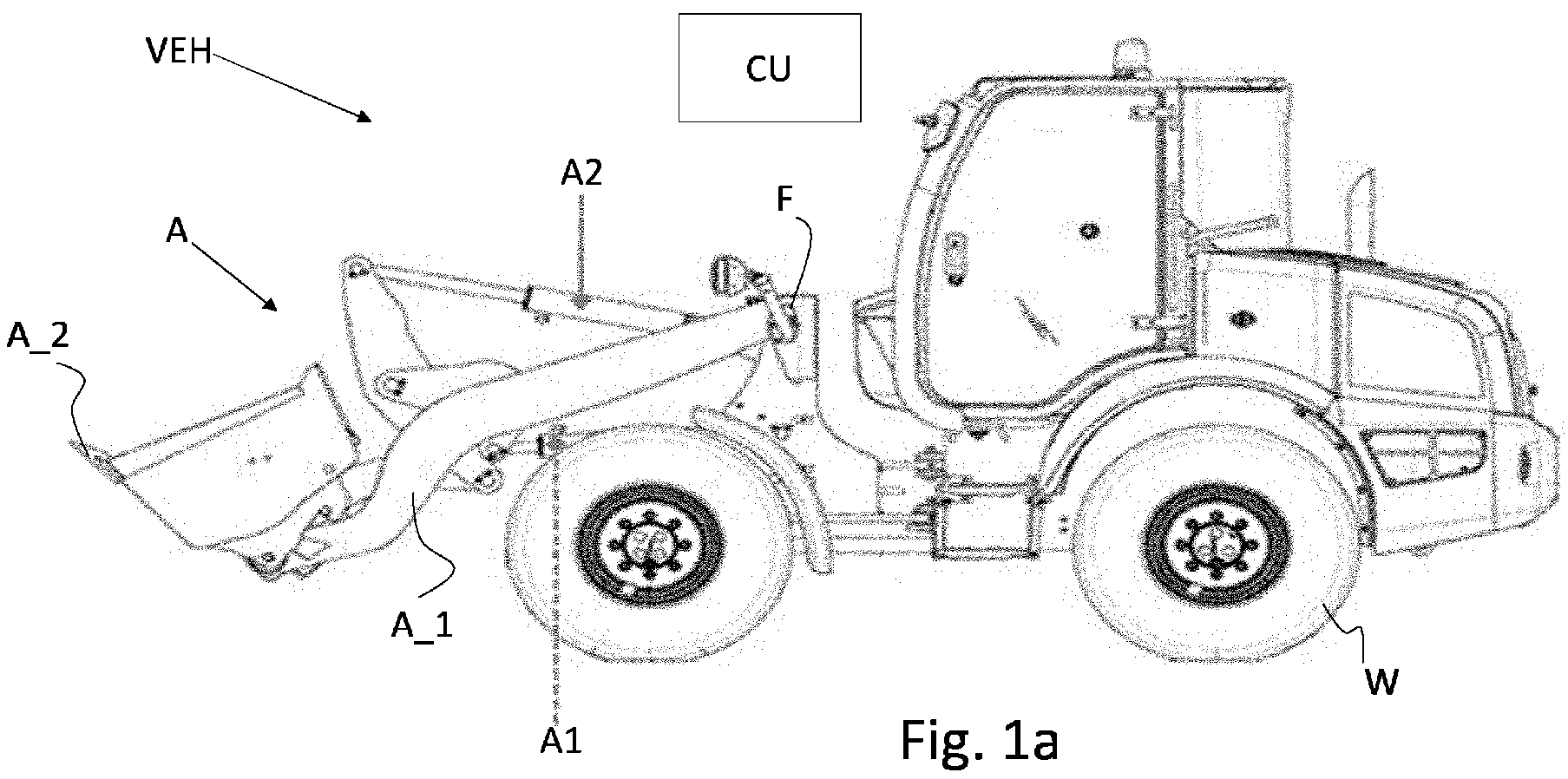
Fig. 1a shows a work vehicle with its arm in any of the possible configurations it can assume, -
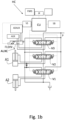
Fig. 1b shows a hydraulic circuit for implementing an articulated arm and auxiliary functions according toFig. 1a ; -
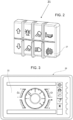
Figs. 2 - 4 show examples of human/machine interfaces. In particular,Fig. 2 shows a button panel,Fig. 3 an instrument panel andFig. 4 a joystick; -
Fig. 5 shows an example of a flow diagram representative of the method object of the present invention. - The same reference numbers and letters in the figures designate equal or functionally equivalent parts.
- According to the present invention, the term "second element" does not imply the presence of a "first element", first, second, etc. They are used only to enhance the clarity of the description and should not be construed in a restrictive manner.
-
Figure 1a illustrates a construction vehicle such as a VHE wheel loader equipped with an arm A including a first element A_1, substantially elongated, hinged to the vehicle chassis F and a second element A_2, such as a bucket or a fork, hinged to the first element. More specifically, a first end of the first element A_1 is connected to the chassis F of the vehicle, while a second end, opposite to the first, supports the second element. - It is clear that the first element can assume more angular positions with respect to the frame F.
- The hydraulic actuator A1 is arranged to control the angular position of the first element A_1 with respect to the vehicle chassis.
- The hydraulic actuator A2 is arranged to control the angular position of the second element A_2 with respect to the first element A_1.
- The hydraulic actuators A1, A2 are of the double action type, with two opposing chambers separated by a mobile partition integral with the stem of the respective actuator.
- With reference to the hydraulic circuit HC shown in
Fig. 1b , a first electro-hydraulic valve V1 is arranged to control the connection of each of said opposite chambers of the actuator A1 alternatively with a source of hydraulic oil P or with the hydraulic oil collection tank T. - The first valve is therefore arranged to control the raising or lowering of the arm.
- Generally, when one chamber is connected with the hydraulic oil source, the opposite chamber is connected with the collection tank. This allows to raise or lower the articulated arm. However, when the arm is stationary, i.e. in static conditions, and at least partially raised, the first chamber of the hydraulic actuator is kept pressurized and closed, i.e. disconnected from both the source of hydraulic oil and the collection tank.
- A second electro-hydraulic valve V2 is arranged to control the oscillation of the bucket with respect to the arm.
- A third electro-hydraulic valve V3 is arranged to control the connection with each of the opposing chambers of an auxiliary device alternatively with the hydraulic oil source P or with the hydraulic oil collection tank T.
- A further valve FLDIV is arranged to switch the hydraulic connection between a first auxiliary hydraulic device AUX and a second auxiliary hydraulic device ADAUX via the aforementioned third electro-hydraulic valve V3.
- AUXC indicates the portion of the electro-hydraulic circuit HC relating to the power supply and control of at least one auxiliary device.
- An electro-hydraulic valve, generally with an open centre, therefore takes care of the control of the respective hydraulic actuator.
- The activation of valves V1, V2 is controlled by a human/machine interface device, such as a joystick JK, shown in
Fig. 4 . - Similarly, a human/machine interface device, which may or may not coincide with a button or lever, for example the
wheel 26 present on the joystick, allows you to control the operation of an auxiliary hydraulic device. - According to the present invention, the processing unit CU is configured to monitor the operation of the vehicle to recognize a reading mission, i.e. a mission in which the vehicle moves from one work location to another for a predetermined time interval, not necessarily continuous. When the processing unit recognizes that the vehicle is in reading conditions and the oil temperature is lower than a predetermined threshold, it suggests the activation of the hydraulic oil warm-up function.
- The hydraulic oil warm-up function is achieved by controlling the third valve V3 in order to power the auxiliary hydraulic device, which, not being connected to the vehicle, involves the lamination of the oil through an overpressure valve (not shown).
- In fact, it is the operator's responsibility to activate the hydraulic oil warm-up function after having ascertained that there is no auxiliary device actually connected to the auxiliary hydraulic circuit, otherwise, the circulation of hydraulic oil in the auxiliary circuit would lead to the movement of the auxiliary device.
- For this purpose, the message shown on the display can preferably remind the operator to activate the hydraulic oil warm-up function after having verified that there is no auxiliary device connected to the auxiliary hydraulic circuit. There may be various buttons on the joystick, the functionality of which may be fixed or programmable depending on the settings given by the operator via the
panel 21 inFig. 2 or theinstrument panel 20 shown inFig. 3 . - Preferably, the joystick further comprises at least one
button - According to the present invention, a first software module is responsible for monitoring the configurations assumed by the arm and the activation of the propulsion system and determining the current mission of the vehicle.
- Based on this recognition, it is verified whether the current mission coincides with a reading mission.
- Evidently, a second software module can be provided configured to receive the current recognized mission as input and to access a look up table in which the functions relating to this mission are listed.
- More preferably, a processing unit CU is configured to implement the first and second software modules and to control the
instrument panel 20 in particular to play messages via therespective display 22. - In particular, the processing unit is configured to check whether the oil temperature is lower than a predetermined threshold, for example 25°C and, consequently, to suggest the activation of the hydraulic oil warm-up function by the activation of the aforementioned third electro-hydraulic valve V3.
- In particular, when the vehicle carries out a reading mission repetitively for at least a predetermined time interval, for example 30 minutes, the suggestion message is shown on the display.
- The message, in particular, suggests activating the automatic oil warm-up function after verifying the absence of any auxiliary device connected to the hydraulic circuit. Enabling the hydraulic oil warm-up function can also be suggested when the hydraulic oil temperature exceeds the aforementioned threshold, for example 25°C. So when the temperature drops below this threshold of 25°C then the function, previously enabled, is automatically activated by the processing unit CU.
- Therefore, enabling this function, in itself, does not cause the activation of the function as long as the oil temperature is higher than the aforementioned temperature threshold.
- The auxiliary devices are generally connected to the hydraulic circuit through quick-connection valves, which allow the auxiliary device to be powered automatically upon connection with the vehicle.
- These quick connection valves close automatically when no auxiliary device is connected therewith.
- Upstream of the quick-connection valves there is generally an overpressure valve designed to discharge excess oil into the collection tank.
- Therefore, when the circulation of hydraulic oil in the auxiliary circuit is enabled, the oil is entirely laminated through the pressure relief valve causing the hydraulic oil to heat up.
- With reference to
Fig. 5 , an exemplary flow diagram of the present invention is shown. The dotted blocks are optional: - Step 1: Observation of frequency and time duration of each operational configuration of the articulated arm and activation of the propulsion system and acquisition of a current hydraulic oil temperature value;
- Step 2: determination of the vehicle's current mission;
- Step 3: checking whether said vehicle mission coincides with a reading mission; in positive case:
- Step 4: Suggestion to enable the hydraulic oil warm-up function, then
- Step 5: checking if the hydraulic oil warm-up function is enabled and the oil temperature is lower than a predetermined threshold, then if so:
- Step 6: activation of the hydraulic oil warm-up function by activating said auxiliary hydraulic circuit and then starting again from
step 1, while if not, starting again directly fromstep 1. - After the automatic or operator enabling of hydraulic oil warm-up function, the system returns to determining the current mission and monitoring the hydraulic oil temperature. Only when the oil temperature drops below said predetermined threshold is the oil warm-up function actually activated. According to a preferred variant of the invention, the first software module is configured to detect the vehicle mission as a function of the frequency balance of the arm configurations and the respective time durations and as a function of the transmission enablement and the frequency of the values discrete vehicle speeds and respective durations. A position sensor is associated with each hydraulic actuator, therefore, it is immediate to acquire the operating configurations of the arm over time and analyse the frequency in discrete domains.
- To make the solution easily implementable, the domains are segmented in such a way that the mutual positions of the elements composing the arm, which fall within a segment, are assumed to be approximately in the middle of the same segment. For further details, see the Applicant's
European patent application n.21217267 - It is worth highlighting that suggestions can be given to the operator not only through writings that appear on the instrument panel or by the flashing of a light associated with an automatic function enable button, but also through voice messages.
- Likewise, the operator can confirm the enablement of the hydraulic oil warm-up function vocally.
- Therefore, the processing unit can advantageously be equipped with a speech synthesis module, an acoustic speaker and/or a microphone to give suggestions to the operator or to receive orders given by the operator.
- The present invention may advantageously be implemented in a computer program comprising program code means for performing one or more steps of such method, when such program is executed on a computer. For this reason, the patent will also cover such computer program and computer readable medium comprising a recorded message, such computer readable medium comprising program code means for carrying out one or more steps of such method, when such program is run on a computer.
- Many changes, modifications, variations and other uses and applications of the subject invention will be apparent to those skilled in the art after considering the accompanying description and drawings, which describe preferred embodiments thereof as described in the accompanying claims.
- The features disclosed in the background of the prior art are introduced only to better understand the invention and not as a statement about the existence of the prior art. Furthermore, said characteristics define the context of the present invention, therefore such characteristics will be considered in common with the detailed description.
- Further implementation details will not be described, as the person skilled in the art is able to implement the invention starting from the teaching of the above description.
Claims (7)
- Computer-operated method for thermal management of a hydraulic circuit of an agricultural or work vehicle, wherein the vehicle is equipped with- an articulated arm (A) connected to a chassis (F) of the vehicle such as to assume a plurality of operating configurations,- a propulsion system that allows the vehicle to be moved with respect to a support surface,- a hydraulic circuit (HC) including a source (P) of pressurized hydraulic oil and a collection tank (T) and at least one auxiliary hydraulic circuit (AUXC) including a valve (V3) for supplying an auxiliary user (AUX , ADAUX),- a human/machine interface device (20) to administer a recorded message,the method including in cyclic succession:- (Step 1) Observation, for a predetermined time interval, of a frequency and duration of each operational configuration and activation of the propulsion system,- (Step 2) Determining a current mission of the vehicle,- (Step 3) checking whether said vehicle mission coincides with a reading mission, and if so, then- (Step 4) suggestion via said human/machine interface device (20) to enable a hydraulic oil warm-up function;wherein said hydraulic oil warm-up function includes the opening of said valve (V3) for the circulation of hydraulic oil in said at least one auxiliary hydraulic circuit (AUXC).
- Method according to claim 1, wherein said observation step (Step 1) comprises an acquisition of a current temperature value of the hydraulic oil and wherein the method comprises- (Step 5) checking whether the hydraulic oil warm-up function is enabled and whether said temperature value is lower than a predetermined threshold and if so,- (Step 6) activation of the hydraulic oil warm-up function.
- Method according to claim 1 or 2, wherein said suggestion comprises a recorded message which includes a warning to verify in advance the absence of any auxiliary user connected to said auxiliary circuit.
- Method according to any one of the preceding claims 1-3, comprising a preliminary step of arranging in said auxiliary circuit at least one overpressure valve arranged to laminate hydraulic oil into a collection tank (T), when said valve (V3) is open and no auxiliary user is connected to said auxiliary circuit.
- A computer program comprising computer program code means adapted to perform all steps of claims 1 - 3, when said program is executed on a control unit of an agricultural or work vehicle.
- A computer readable medium having stored the program of claim 5.
- Work or agricultural vehicle (VEH) comprising an articulated arm (A) connected to a chassis (F) of the vehicle such as to assume a plurality of operating configurations, a propulsion system such as to allow movement of the vehicle with respect to a surface support, a hydraulic circuit (HC) including a source (P) of pressurized hydraulic oil and a collection tank (T) and at least one auxiliary hydraulic circuit (AUXC) including a valve (V3) for supplying an auxiliary user (AUX, ADAUX), a human/machine interface device (20), associated with a vehicle dashboard to administer a recorded message, a processing unit (VCU) configured to observe, for a predetermined time interval, a frequency and time duration of each operational configuration, and a frequency and duration of activation of the propulsion system and consequently to determine a current mission of the vehicle and to verify whether said mission of the vehicle coincides with a reading mission, and if so to suggest an enabling of a hydraulic oil warm-up function, wherein the warm-up function includes circulating hydraulic oil through said auxiliary hydraulic circuit (AUXC).
Applications Claiming Priority (1)
| Application Number | Priority Date | Filing Date | Title |
|---|---|---|---|
| IT102023000027708A IT202300027708A1 (en) | 2023-12-21 | 2023-12-21 | METHOD OF THERMAL MANAGEMENT OF A HYDRAULIC CIRCUIT OF AN AGRICULTURAL OR WORK VEHICLE AND A CONTROL UNIT IMPLEMENTING THE METHOD |
Publications (1)
| Publication Number | Publication Date |
|---|---|
| EP4575105A1 true EP4575105A1 (en) | 2025-06-25 |
Family
ID=89983484
Family Applications (1)
| Application Number | Title | Priority Date | Filing Date |
|---|---|---|---|
| EP24221226.4A Pending EP4575105A1 (en) | 2023-12-21 | 2024-12-18 | Thermal management method for a hydraulic circuit of an agricultural or work vehicle and a control unit implementing the method |
Country Status (2)
| Country | Link |
|---|---|
| EP (1) | EP4575105A1 (en) |
| IT (1) | IT202300027708A1 (en) |
Citations (3)
| Publication number | Priority date | Publication date | Assignee | Title |
|---|---|---|---|---|
| JP2021156398A (en) * | 2020-03-27 | 2021-10-07 | 住友建機株式会社 | Shovel |
| JP2022033079A (en) * | 2020-08-15 | 2022-02-28 | 株式会社クボタ | Work machine |
| EP4026954A1 (en) * | 2021-01-07 | 2022-07-13 | CNH Industrial Italia S.p.A. | Method for detecting a work or agricultural vehicle mission through a neural network and control unit implementing the method |
-
2023
- 2023-12-21 IT IT102023000027708A patent/IT202300027708A1/en unknown
-
2024
- 2024-12-18 EP EP24221226.4A patent/EP4575105A1/en active Pending
Patent Citations (3)
| Publication number | Priority date | Publication date | Assignee | Title |
|---|---|---|---|---|
| JP2021156398A (en) * | 2020-03-27 | 2021-10-07 | 住友建機株式会社 | Shovel |
| JP2022033079A (en) * | 2020-08-15 | 2022-02-28 | 株式会社クボタ | Work machine |
| EP4026954A1 (en) * | 2021-01-07 | 2022-07-13 | CNH Industrial Italia S.p.A. | Method for detecting a work or agricultural vehicle mission through a neural network and control unit implementing the method |
Also Published As
| Publication number | Publication date |
|---|---|
| IT202300027708A1 (en) | 2025-06-21 |
Similar Documents
| Publication | Publication Date | Title |
|---|---|---|
| JP2025100796A (en) | Excavator | |
| US20180150070A1 (en) | Portable inspection and control device | |
| CN102164767B (en) | Power take-off control system driven by traction motor of hybrid electric vehicle | |
| CN205942833U (en) | Can be used to intelligent system of robot among estate management | |
| DE102011002470A1 (en) | Vehicle maintenance consultant for an emotive advisory system | |
| CA2878041A1 (en) | Scannable codes to display machine information | |
| JP2001003395A (en) | Operation characteristic control method for sub-system of machine and its device | |
| EP4575105A1 (en) | Thermal management method for a hydraulic circuit of an agricultural or work vehicle and a control unit implementing the method | |
| CN108138505B (en) | Adaptive control of hydraulic tools on a remote demolition robot | |
| CN105022294A (en) | Portable communication device with driving state man-machine interface, system and working method | |
| CN108086857A (en) | Automobile rises window control device and system | |
| JP2019056234A (en) | Work machine | |
| RU2754877C2 (en) | Tracked vehicle and tracked vehicle fleet | |
| CN118012008A (en) | Vehicle fault diagnosis method, controller and storage medium | |
| US20160114818A1 (en) | System for remotely overriding locomotive controls | |
| JP5111184B2 (en) | Data communication system for work equipment | |
| EP4575099A1 (en) | Method for supporting completion of a mission of an agricultural or work vehicle and a control unit implementing the method | |
| EP2910746B1 (en) | Multi-step regeneration device of dpf and regeneration method therefor | |
| EP4575100A1 (en) | Method for supporting completion of a mission of an agricultural or work vehicle and a control unit implementing the method | |
| EP4077978B1 (en) | Systems and methods for bypass of hydraulic charge circuits | |
| EP4737648A1 (en) | Method of supporting the execution of a mission of an agricultural or work vehicle and a control unit implementing the method | |
| US6192301B1 (en) | Self-diagnostic method for a forklift truck | |
| CN205971079U (en) | Integrated have driver to train rear -view mirror of managing automobile -mounted terminal | |
| EP4575096A1 (en) | Method for supporting an execution of a mission of an agricultural or work vehicle and a control unit implementing the method | |
| CN2578184Y (en) | Fingerprint controller of vehicle |
Legal Events
| Date | Code | Title | Description |
|---|---|---|---|
| PUAI | Public reference made under article 153(3) epc to a published international application that has entered the european phase |
Free format text: ORIGINAL CODE: 0009012 |
|
| STAA | Information on the status of an ep patent application or granted ep patent |
Free format text: STATUS: THE APPLICATION HAS BEEN PUBLISHED |
|
| AK | Designated contracting states |
Kind code of ref document: A1 Designated state(s): AL AT BE BG CH CY CZ DE DK EE ES FI FR GB GR HR HU IE IS IT LI LT LU LV MC ME MK MT NL NO PL PT RO RS SE SI SK SM TR |
|
| STAA | Information on the status of an ep patent application or granted ep patent |
Free format text: STATUS: REQUEST FOR EXAMINATION WAS MADE |
|
| 17P | Request for examination filed |
Effective date: 20260102 |