EP4575071A1 - A laundry care device and a pull-out box thereof - Google Patents
A laundry care device and a pull-out box thereof Download PDFInfo
- Publication number
- EP4575071A1 EP4575071A1 EP24216931.6A EP24216931A EP4575071A1 EP 4575071 A1 EP4575071 A1 EP 4575071A1 EP 24216931 A EP24216931 A EP 24216931A EP 4575071 A1 EP4575071 A1 EP 4575071A1
- Authority
- EP
- European Patent Office
- Prior art keywords
- handle
- assembly
- care device
- laundry care
- base board
- Prior art date
- Legal status (The legal status is an assumption and is not a legal conclusion. Google has not performed a legal analysis and makes no representation as to the accuracy of the status listed.)
- Pending
Links
Images



Classifications
-
- D—TEXTILES; PAPER
- D06—TREATMENT OF TEXTILES OR THE LIKE; LAUNDERING; FLEXIBLE MATERIALS NOT OTHERWISE PROVIDED FOR
- D06F—LAUNDERING, DRYING, IRONING, PRESSING OR FOLDING TEXTILE ARTICLES
- D06F39/00—Details of washing machines not specific to a single type of machines covered by groups D06F9/00 - D06F27/00
- D06F39/02—Devices for adding soap or other washing agents
-
- D—TEXTILES; PAPER
- D06—TREATMENT OF TEXTILES OR THE LIKE; LAUNDERING; FLEXIBLE MATERIALS NOT OTHERWISE PROVIDED FOR
- D06F—LAUNDERING, DRYING, IRONING, PRESSING OR FOLDING TEXTILE ARTICLES
- D06F39/00—Details of washing machines not specific to a single type of machines covered by groups D06F9/00 - D06F27/00
- D06F39/12—Casings; Tubs
Definitions
- This application relates to a laundry care device, and further relates to a pull-out box of the laundry care device.
- Laundry care devices such as washing machines or drying machines usually have a pull-out box such as a detergent drawer. During use, the pull-out box needs to be pulled out of a shell to add a detergent or the like.
- the laundry care devices on the market have an opening portion arranged on an outer surface of the pull-out box to accommodate a human hand to operate. The outer surface has complex lines and the opening exposes an internal structure, which is unaesthetic and not easy to keep clean, affecting overall styling and user experience of the laundry care device.
- an objective of this application is to provide an improved laundry care device and a pull-out box thereof.
- a laundry care device including a housing and a pull-out box slidably supported on the housing along a pull-out direction.
- the pull-out box includes a box body and a handle assembly connected to each other.
- the handle assembly includes a base board, a handle, and an engaging mechanism.
- the base board is fixedly connected to the box body.
- the handle is slidably connected to the base board along the pull-out direction and has a holding position away from the base board and a closed position close to the base board.
- the engaging mechanism is located between the handle and the base board and is capable of keeping the handle in the holding position and the closed position separately.
- An optional implementation includes that, the housing has a housing outside, the handle has a holding portion, and the engaging mechanism is capable of converting the handle between a first state and a second state, where in the first state, the handle and the holding portion are substantially received in the housing, and the handle is in the closed position, and in the second state, the handle and the holding portion protrude from the housing outside of the laundry care device adjacent to the handle, and the handle is in the holding position.
- an outer side of the handle assembly is flush with the housing outside of the laundry care device adjacent to the handle assembly.
- the outer side of the handle assembly and the housing outside of the laundry care device have similar and/or identical and/or consistent characteristics.
- the handle assembly further includes a decorative cover, where the decorative cover is arranged at least on the handle, an outer side of the decorative cover forms an entire outer side of the handle assembly, and in the first state, the outer side of the decorative cover is flush with the housing outside of the laundry care device adjacent to the decorative cover.
- the outer side of the handle assembly is substantially a plane, and the housing outside of the laundry care device is also substantially a plane.
- An optional implementation further includes that the engaging mechanism includes a driving mechanism, and the driving mechanism is capable of providing a driving force for converting the handle between the closed position and the holding position.
- the driving mechanism includes a push-push locking assembly and at least one elastic element.
- the push-push locking assembly includes a snap-lock element and a locking element. Further, one of the snap-lock element and the locking element is arranged on the handle, and the other of the snap-lock element and the locking element is arranged on the base board.
- the elastic element is arranged between the handle and the base board.
- An optional implementation further includes that the engaging mechanism includes a sliding mechanism, and the handle is slidably supported on the base board along the sliding mechanism.
- the sliding mechanism includes a guide rail and a protruding element.
- one of the guide rail and the protruding element is constructed on the handle, and the other of the guide rail and the protruding element is constructed on the base board.
- the guide rail is a guide hole
- the protruding element is a guide column that passes through the guide hole and slides along an inner peripheral surface of the guide hole.
- the guide rail is arranged on the base board, and the protruding element is arranged on the handle.
- the engaging mechanism includes a positioning mechanism and a limiting mechanism.
- the positioning mechanism includes a first positioning assembly and a second positioning assembly
- the limiting mechanism includes a first limiting assembly and a second limiting assembly
- the handle is positioned and limited in the closed position through the first positioning assembly and the first limiting assembly, and is positioned and limited in the holding position through the second positioning assembly and the second limiting assembly.
- the first positioning assembly includes a first positioning rib and a second positioning rib that match each other and that are respectively arranged on the handle and the base board, and the first positioning rib and the second positioning rib define displacements of the handle relative to the base board in at least two directions on a plane perpendicular to the pull-out direction.
- the first limiting assembly includes locking portions of the snap-lock element and the locking element.
- the second positioning assembly includes fitting portions of the protruding element and the guide rail in a circumferential direction in the holding position.
- the second limiting assembly includes a snap at an end portion of the protruding element and an end surface of the guide rail that fits the snap.
- An optional implementation further includes that the pull-out box is at least one of a detergent feeding box, a condensate water collection box, and a lint collection box.
- a pull-out box is provided, used for the laundry care device according to any one of the foregoing embodiments.
- the handle only when a user needs to pull the pull-out box out of the housing of the laundry care device, the handle is kept in the second state and the holding position to open or close the pull-out box; when the pull-out box does not need to be used or operated, the handle is always kept in the first state and the closed position. That is, the handle is substantially received in the housing of the laundry care device, so that an appearance of the pull-out box is more compact, integrated, and aesthetic. A sense of existence of the pull-out box in an overall appearance of the laundry care device is reduced, and it is easier to keep clean and safer.
- the handle is slidably connected along the pull-out direction, so that a force acting on the handle is transferred to the box body evenly, and the pull is smoother, providing better user experience and better ergonomics.
- the sliding connection does not need to provide avoidance space for movement of the handle on a structure on the laundry care device adjacent to the handle, so that the handle has a small gap with an adjacent structural member, and the appearance is more integrated and aesthetic.
- the engaging mechanism is arranged between the handle and the base board, is used as a part of the pull-out box and the handle assembly, has little relevance to a mounting space or the box body of the pull-out box, facilitates maintenance, disassembly, and assembly of the handle assembly and the pull-out box, and has strong compatibility. Only the handle part is movable, and the pull-out box can be operated with space left for a human hand to operate. A sliding distance is short, a design requirement for the engaging mechanism is low, and a gap and a step on the appearance surface are more easily ensured.
- orientation terms or direction terms are relative to a routine use state of a drum washing machine.
- a person skilled in the art may clarify this from the description of this application without causing confusion.
- the orientation terms and direction terms should not be construed simply as indicating an orientation or direction in any state.
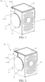
- FIG. 1 and FIG. 2 show a laundry care device 100.
- the laundry care device 100 exemplarily shown in FIG. 1 and FIG. 2 may be, for example, a washing machine, a drying machine, or a washing and drying machine.
- the laundry care device 100 includes a housing 10, and the housing 10 has a housing outside 11.
- a drum (not shown in the figure) defining a laundry care cavity is arranged in the housing 10, and the housing 10 substantially includes a front wall 101, a side wall 102, and a top plate 103.
- the housing outside 11 of the front wall 101 of the laundry care device 100 is substantially considered.
- the laundry care device 100 includes at least one opening (not shown in the figure).
- the opening is constructed in the front wall 101 of the housing 10.
- the opening may be closed by a door unit 20.
- the door unit 20 is substantially connected to the housing 10 in an anti-torsion manner or fastened on the housing 10 in a rotatable manner.
- a pull-out box 30 is schematically shown in an upper region of the front wall 101 of the laundry care device 100, and the pull-out box 30 is slidably supported on the housing 10 along a pull-out direction D.
- the pull-out box 30 is a detergent adding box.
- the pull-out box 30 may alternatively be a condensate water collection box, a lint collection box, or the like.
- a control panel (not shown in the figure) may be further arranged on the front wall 101 of the laundry care device 100, for example, arranged in the upper region of the front wall 101 together with the pull-out box 30.
- An outer side of a front surface of the control panel forms a part of the housing outside 11 of the front wall 101 of the laundry care device 100.
- the pull-out box 30 may alternatively be arranged in another region of the front wall 101 of the laundry care device 100 as required.
- a control portion, a display portion, and the like may be arranged on the control panel.
- the control portion may be a touch control or a mechanical control such as a knob or a button.
- FIG. 3 shows a pull-out box 30, where the pull-out box 30 has a box body 30a and a handle assembly 30b that are exemplarily shown.
- the box body 30a is configured to receive a detergent in a liquid state and/or a gel state and/or a powder state.
- the handle assembly 30b is mounted on the box body 30a.
- the handle assembly 30b includes a decorative cover 31, a handle 32, a base board 33, and an engaging mechanism 34 located between the handle 32 and the base board 33.
- the base board 33 is fixedly connected to the box body 30a.
- the base board 33 includes at least one connecting element 331, where the at least one connecting element 331 is configured to connect the handle assembly 30b to the box body 30a, thereby forming the pull-out box 30.
- the handle 32 is slidably connected to the base board 33 along the pull-out direction D and has a holding position away from the base board 33 and a closed position close to the base board 33.
- the engaging mechanism 34 is capable of keeping the handle 32 in the holding position and the closed position separately.
- the handle 32 includes a holding portion 321.
- the handle assembly 30b includes only one handle 32 and one holding portion 321.
- the handle assembly 30b may alternatively have a plurality of handles 32 and a plurality of holding portions 321.
- the holding portion 321 is preferably constructed in a lower region of the handle 32.
- the handle 32 and the holding portion 321 protrude from the housing outside 11 of the laundry care device 100 adjacent to the handle 32, and the handle 32 is in the holding position.
- a user can reach the holding portion 321 and operate the handle 32 through the holding portion 321 to open or close the box body 30a of the pull-out box 30.
- the decorative cover 31 is arranged toward the housing outside 11.
- the decorative cover 31 may be constructed in one piece or formed by a plurality of sub-elements.
- the decorative cover 31 and the housing outside 11 (especially the front wall 101) of the laundry care device 100 preferably have similar and/or identical and/or consistent characteristics (or compositions), including but not limited to color compositions, material compositions, and the like.
- the decorative cover 31 is arranged at least on the handle 32.
- the handle 32 covers an entire surface of the base board 33, and the decorative cover 31 is substantially constructed as a plate and fastened to the handle 32 by bonding or another manner, to cover the handle 32.
- an outer side of the decorative cover 31 forms an entire outer side of the handle assembly 30b, so that there is no division line on the entire outer side of the handle assembly 30b.
- the outer side of the decorative cover 31 is flush with the housing outside 11 of the laundry care device 100 adjacent to the decorative cover 31.
- the handle 32 may cover only a part of the base board 33, and the decorative cover 31 includes a first decorative cover arranged on the handle 32 and a second decorative cover arranged on the remaining part of the base board 33.
- outer sides of the first decorative cover and the second decorative cover form the entire outer side of the handle assembly 30b, and are both flush with the housing outside 11 of the laundry care device 100 adjacent to the decorative cover 31. Therefore, a substantially coherent front wall 101 or a flat front wall is visually created.
- the front wall substantially only the door unit 20 protrudes from the housing outside 11 of the front wall 101 of the laundry care device 100.
- the outer side of the decorative cover 31 is substantially a plane.
- the decorative cover 31 may not be arranged, and instead the handle 32 or the handle 32 and an outer side of the base board 33 form the outer side of the handle assembly 30b.
- the handle 32 and/or the base board 33 and the housing outside 11 (especially the front wall 101) of the laundry care device 100 preferably have similar and/or identical and/or consistent characteristics (or compositions).
- the engaging mechanism 34 includes a driving mechanism 341.
- the driving mechanism 341 can provide a driving force for converting the handle between the first state (the closed position) and the second state (the holding position).
- the driving mechanism 341 is constructed as a push-push locking assembly 3411 and at least one elastic element 3412.
- the at least one elastic element 3412 may be a spring element or a spring-like element, which may be tensioned.
- the elastic element 3412 is constructed as a compression spring. Other spring-like elements are also feasible.
- the elastic element 3412 in this embodiment is shown in a substantially relaxed state in FIG. 4 .
- the driving mechanism 341 may alternatively be constructed as a micro-motor driving mechanism, an electromagnetic driving mechanism, or the like.
- the push-push locking assembly 3411 preferably includes a snap-lock element 3411a and a locking element 3411b, one of which is arranged on the base board 33, and the other of which is constructed on the handle 32.
- the locking element 3411b may be constructed as, for example, a locking hook and/or a locking pin.
- the locking element 3411b is constructed to be receivable by the snap-lock element 3411a, or the locking element 3411b is constructed to be pushable into the snap-lock element 3411a, so that the locking element 3411b is received in the snap-lock element 3411a. If the locking element 3411b is pushed into or received in the snap-lock element 3411a, the handle 32 is kept in the closed position.
- the elastic element 3412 In the first state of the handle 32 in FIG. 1 , the elastic element 3412 is tensioned. In the second state of the handle 32 in FIG. 2 , the elastic element 3412 is relaxed. After the locking element 3411b is unlocked from the snap-lock element 3411a, the elastic element 3412 causes the handle 32 to be pressed open/out.
- the elastic element 3412 is arranged between the handle 32 and the base board 33.
- the elastic element 3412 is arranged on the base board 33 and abuts against the handle 32 and/or the decorative cover 31.
- the engaging mechanism 34 further includes a sliding mechanism 342, and the handle 32 is slidably supported on the base board 33 along the sliding mechanism 342.
- the sliding mechanism 342 includes a guide rail 3421 and a protruding element 3422.
- One of the guide rail 3421 and the protruding element 3422 is constructed on the handle 32, and the other is constructed on the base board 33.
- the guide rail 3421 is a guide hole
- the protruding element 3422 is a guide column that passes through the guide hole and slides along an inner peripheral surface of the hole.
- the guide rail 3421 is arranged on the base board 33, and the protruding element 3422 is arranged on the handle 32.
- the protruding element 3422 is guided or supported in a guided manner in the guide rail 3421.
- four guide rails 3421 and four protruding elements 3422 are constructed, which are preferably constructed in four peripheral regions of the base board 33 and four peripheral regions of the handle 32 respectively. It may be understood that a quantity of guide rails 3421 and a quantity of protruding elements 3422 may alternatively be set as required, and the quantity of protruding elements 3422 matches the quantity of guide rails 3421.
- the engaging mechanism 34 further includes a positioning mechanism 343 and a limiting mechanism 344.
- the positioning mechanism 343 includes a first positioning assembly 3431 and a second positioning assembly 3432.
- the limiting mechanism 344 includes a first limiting assembly 3441 and a second limiting assembly 3442.
- the handle 32 is positioned and limited in the holding position through the first positioning assembly 3431 and the first limiting assembly 3441, and is positioned and limited in the closed position through the second positioning assembly 3432 and the second limiting assembly 3442.
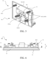
- FIG. 6 and FIG. 7 are a schematic diagram and a cross-sectional view of the handle assembly 30b in the closed position.
- the first positioning assembly 3431 includes a first positioning rib 3431a and a second positioning rib 3431b that match each other and that are respectively arranged on the handle 32 and the base board 33.
- the first positioning rib 3431a and the second positioning rib 3431b define displacements of the handle 32 relative to the base board 33 in horizontal and vertical directions on a plane perpendicular to the pull-out direction D. In other embodiments, displacements in at least two other directions may alternatively be defined.
- the handle 32 and the base board 33 are limited in the pull-out direction in the closed position through the first limiting assembly 3441.
- the first limiting assembly 3441 includes locking portions of the snap-lock element 3411a and the locking element 3411b.
- FIG. 8 to FIG. 10 are schematic diagrams and a cross-sectional view of the handle assembly 30b in the holding position.
- the second positioning assembly 3432 includes fitting portions of the protruding element 3422 and the guide rail 3421 in a circumferential direction in the holding position, including a protruding element fitting portion 3432a and a guide rail fitting portion 3432b.
- the protruding element fitting portion 3432a is an outer periphery of at least two radially extending bosses arranged on an outer periphery at an end of the protruding element 3422 away from the handle 32, and the guide rail fitting portion 3432b is an inner periphery of the guide rail 3421.
- a boss is used as a positioning portion, which facilitates manufacturing, and there is no need to control the entire outer periphery at the end of the protruding element 3422 away from the handle 32.
- an inner peripheral surface of the guide hole used as the guide rail 3421 is a first cylindrical surface
- an outer peripheral surface of the guide column used as the protruding element 3422 is a tapered surface
- a diameter at an end of the tapered surface close to the handle 32 is less than a diameter of an end at the tapered surface away from the handle 32.
- At least two bosses are arranged on an outer periphery at the end of the tapered surface away from the handle 32, outer peripheral surfaces of the at least two bosses are each a part of a second cylindrical surface, and diameters of the first cylindrical surface and the second cylindrical surface are substantially the same.
- the handle 32 and the base board 33 are limited in the pull-out direction in the holding position through the second limiting assembly 3442.
- the second limiting assembly 3442 includes a snap 3442a at an end portion of the protruding element 3422 away from the handle 32 and an end surface 3442b of the guide rail 3421 that fits the snap 3442a in the holding position.
- the handle 32 and the decorative cover 31 are converted from the first state to the second state.
- the handle 32 and the decorative cover 31 are in the first state, in which the handle 32 and the decorative cover 31 are substantially received in the housing 10 of the laundry care device 100, and the handle 32 and the decorative cover 31 are in the closed position.
- the locking element 3411b is disengaged from the snap-lock element 3411a.
- the elastic element 3412 tensioned in the first state causes the handle 32 and the decorative cover 31 to be pressed out. Because the handle 32 and the decorative cover 31 are slidably supported on the base board 33 through the sliding mechanism 342, the handle 32 and the decorative cover 31 are slidably moved and smoothly converted from the first state to the second state through the elastic element 3412.
- the handle 32 and the decorative cover 31 extend from the housing 10 of the laundry care device 100 in such a way that the holding portion 321 of the handle 32 can be operated from the outside, that is, the handle 32 and the decorative cover 31 are in the holding position.
- the pull-out box 30 may be pulled out from the housing 10 of the laundry care device 100 through the holding portion 321.
- the handle 32 and the decorative cover 31 are pressed in, so that the elastic element 3412 is tensioned again and the locking element 3411b is received in the snap-lock element 3411a.
- the handle 32 and the decorative cover 31 are received in the laundry care device 100 in the first state.
Landscapes
- Engineering & Computer Science (AREA)
- Textile Engineering (AREA)
- Detail Structures Of Washing Machines And Dryers (AREA)
Abstract
This application discloses a laundry care device (100), including a housing (10) and a pull-out box (30) slidably supported on the housing along a pull-out direction. The pull-out box includes a box body (30a) and a handle assembly (30b) connected to each other. The handle assembly includes a base board (33), a handle (32), and an engaging mechanism (34). The base board is fixedly connected to the box body. The handle is slidably connected to the base board along the pull-out direction and has a holding position away from the base board and a closed position close to the base board. The engaging mechanism is located between the handle and the base board and is capable of keeping the handle in the holding position and the closed position separately.
Description
- This application relates to a laundry care device, and further relates to a pull-out box of the laundry care device.
- With the improvement in people's living standards and the progress of technologies, more and more household appliances have entered thousands of households to help and enrich people's lives. Consumers' requirements for household appliances are no longer just about functionality, but also about aesthetically pleasing designs. Laundry care devices such as washing machines or drying machines usually have a pull-out box such as a detergent drawer. During use, the pull-out box needs to be pulled out of a shell to add a detergent or the like. Currently, the laundry care devices on the market have an opening portion arranged on an outer surface of the pull-out box to accommodate a human hand to operate. The outer surface has complex lines and the opening exposes an internal structure, which is unaesthetic and not easy to keep clean, affecting overall styling and user experience of the laundry care device.
- Therefore, there is still a need for continuous improvement.
- To overcome one of the foregoing shortcomings and/or other possible shortcomings in the prior art not mentioned herein, an objective of this application is to provide an improved laundry care device and a pull-out box thereof.
- According to a first aspect of this application, a laundry care device is provided, including a housing and a pull-out box slidably supported on the housing along a pull-out direction. The pull-out box includes a box body and a handle assembly connected to each other. The handle assembly includes a base board, a handle, and an engaging mechanism. The base board is fixedly connected to the box body. The handle is slidably connected to the base board along the pull-out direction and has a holding position away from the base board and a closed position close to the base board. The engaging mechanism is located between the handle and the base board and is capable of keeping the handle in the holding position and the closed position separately.
- An optional implementation includes that, the housing has a housing outside, the handle has a holding portion, and the engaging mechanism is capable of converting the handle between a first state and a second state, where in the first state, the handle and the holding portion are substantially received in the housing, and the handle is in the closed position, and in the second state, the handle and the holding portion protrude from the housing outside of the laundry care device adjacent to the handle, and the handle is in the holding position.
- Preferably, in the first state, an outer side of the handle assembly is flush with the housing outside of the laundry care device adjacent to the handle assembly.
- Preferably, the outer side of the handle assembly and the housing outside of the laundry care device have similar and/or identical and/or consistent characteristics.
- Preferably, the handle assembly further includes a decorative cover, where the decorative cover is arranged at least on the handle, an outer side of the decorative cover forms an entire outer side of the handle assembly, and in the first state, the outer side of the decorative cover is flush with the housing outside of the laundry care device adjacent to the decorative cover.
- Preferably, the outer side of the handle assembly is substantially a plane, and the housing outside of the laundry care device is also substantially a plane.
- An optional implementation further includes that the engaging mechanism includes a driving mechanism, and the driving mechanism is capable of providing a driving force for converting the handle between the closed position and the holding position.
- Preferably, the driving mechanism includes a push-push locking assembly and at least one elastic element.
- Preferably, the push-push locking assembly includes a snap-lock element and a locking element. Further, one of the snap-lock element and the locking element is arranged on the handle, and the other of the snap-lock element and the locking element is arranged on the base board.
- Preferably, the elastic element is arranged between the handle and the base board.
- An optional implementation further includes that the engaging mechanism includes a sliding mechanism, and the handle is slidably supported on the base board along the sliding mechanism.
- Preferably, the sliding mechanism includes a guide rail and a protruding element.
- Preferably, one of the guide rail and the protruding element is constructed on the handle, and the other of the guide rail and the protruding element is constructed on the base board.
- Preferably, the guide rail is a guide hole, and the protruding element is a guide column that passes through the guide hole and slides along an inner peripheral surface of the guide hole.
- Preferably, the guide rail is arranged on the base board, and the protruding element is arranged on the handle. An optional implementation further includes that the engaging mechanism includes a positioning mechanism and a limiting mechanism.
- Preferably, the positioning mechanism includes a first positioning assembly and a second positioning assembly, and the limiting mechanism includes a first limiting assembly and a second limiting assembly; and the handle is positioned and limited in the closed position through the first positioning assembly and the first limiting assembly, and is positioned and limited in the holding position through the second positioning assembly and the second limiting assembly.
- Preferably, the first positioning assembly includes a first positioning rib and a second positioning rib that match each other and that are respectively arranged on the handle and the base board, and the first positioning rib and the second positioning rib define displacements of the handle relative to the base board in at least two directions on a plane perpendicular to the pull-out direction.
- Preferably, the first limiting assembly includes locking portions of the snap-lock element and the locking element.
- Preferably, the second positioning assembly includes fitting portions of the protruding element and the guide rail in a circumferential direction in the holding position.
- Preferably, the second limiting assembly includes a snap at an end portion of the protruding element and an end surface of the guide rail that fits the snap.
- An optional implementation further includes that the pull-out box is at least one of a detergent feeding box, a condensate water collection box, and a lint collection box.
- The foregoing embodiments may be combined in any manner as allowed by technical conditions.
- According to a second aspect of this application, a pull-out box is provided, used for the laundry care device according to any one of the foregoing embodiments.
- According to some exemplary embodiments of this application, only when a user needs to pull the pull-out box out of the housing of the laundry care device, the handle is kept in the second state and the holding position to open or close the pull-out box; when the pull-out box does not need to be used or operated, the handle is always kept in the first state and the closed position. That is, the handle is substantially received in the housing of the laundry care device, so that an appearance of the pull-out box is more compact, integrated, and aesthetic. A sense of existence of the pull-out box in an overall appearance of the laundry care device is reduced, and it is easier to keep clean and safer. There is consistency between an outer side of the pull-out box and the housing outside of the laundry care device, so that an overall visual effect of the laundry care device is more concise and integrated, thereby obtaining a high-quality and high-grade appearance. The handle is slidably connected along the pull-out direction, so that a force acting on the handle is transferred to the box body evenly, and the pull is smoother, providing better user experience and better ergonomics. In addition, the sliding connection does not need to provide avoidance space for movement of the handle on a structure on the laundry care device adjacent to the handle, so that the handle has a small gap with an adjacent structural member, and the appearance is more integrated and aesthetic. The engaging mechanism is arranged between the handle and the base board, is used as a part of the pull-out box and the handle assembly, has little relevance to a mounting space or the box body of the pull-out box, facilitates maintenance, disassembly, and assembly of the handle assembly and the pull-out box, and has strong compatibility. Only the handle part is movable, and the pull-out box can be operated with space left for a human hand to operate. A sliding distance is short, a design requirement for the engaging mechanism is low, and a gap and a step on the appearance surface are more easily ensured.
- The following illustrates some specific embodiments of this application with reference to the accompanying drawings.
- The following illustrates some specific embodiments of this application with reference to the accompanying drawings, so that principles, features, and advantages of this application can be better understood. The accompanying drawings include:
-
FIG. 1 is a schematic diagram of a laundry care device in a first state according to an embodiment of this application; -
FIG. 2 is a schematic diagram of a laundry care device in a second state according to an embodiment of this application; -
FIG. 3 is a schematic exploded diagram of a pull-out box of a laundry care device according to an embodiment of this application; -
FIG. 4 is a schematic diagram of a handle and a partial engaging structure of a handle assembly of the pull-out box inFIG. 3 ; -
FIG. 5 is a schematic diagram of a base board and a partial engaging structure of a handle assembly of the pull-out box inFIG. 3 ; -
FIG. 6 is a schematic diagram of a handle assembly of the pull-out box inFIG. 3 in a first state; -
FIG. 7 is a schematic diagram of a cross section along A-A inFIG. 6 ; -
FIG. 8 is a schematic diagram of a handle assembly of the pull-out box inFIG. 3 in a second state; -
FIG. 9 is a schematic diagram of a cross section along B-B inFIG. 8 ; and -
FIG. 10 is a schematic enlarged diagram of a region C inFIG. 9 . - To make the technical problem to be resolved by this application, the technical solutions and the beneficial technical effects of this application clearer and more comprehensible, the following further describes this application in detail with reference to the figures and a plurality of exemplary embodiments. It should be understood that the specific embodiments described herein are merely used to explain this application, instead of limiting the protection scope of this application. In addition, the embodiments may share a same view or a plurality of views for description, but not all features in a same drawing can be interpreted as features necessary to one embodiment. On the contrary, the embodiments may be combined in any suitable manner provided that the embodiments are not technically mutually exclusive. Moreover, for the sake of simplicity, different embodiments of different aspects may be presented in a same specific design, but such presentation does not mean that the embodiments of these aspects should appear together. The disassemble and/or combination of all possible embodiments and/or technical features should also take into account the description of this specification and content that a person skilled in the art can directly and undoubtedly determine based on the description of this specification.
- Before description, it should be pointed out that for the sake of convenience, this specification may use orientation terms or direction terms for description. The orientation terms or direction terms are relative to a routine use state of a drum washing machine. A person skilled in the art may clarify this from the description of this application without causing confusion. In this case, the orientation terms and direction terms should not be construed simply as indicating an orientation or direction in any state.
-
FIG. 1 and FIG. 2 show alaundry care device 100. Thelaundry care device 100 exemplarily shown inFIG. 1 and FIG. 2 may be, for example, a washing machine, a drying machine, or a washing and drying machine. Thelaundry care device 100 includes ahousing 10, and thehousing 10 has a housing outside 11. A drum (not shown in the figure) defining a laundry care cavity is arranged in thehousing 10, and thehousing 10 substantially includes a front wall 101, aside wall 102, and atop plate 103. In this embodiment, the housing outside 11 of the front wall 101 of thelaundry care device 100 is substantially considered. - In addition, the
laundry care device 100 includes at least one opening (not shown in the figure). The opening is constructed in the front wall 101 of thehousing 10. The opening may be closed by adoor unit 20. Thedoor unit 20 is substantially connected to thehousing 10 in an anti-torsion manner or fastened on thehousing 10 in a rotatable manner. In addition, a pull-out box 30 is schematically shown in an upper region of the front wall 101 of thelaundry care device 100, and the pull-out box 30 is slidably supported on thehousing 10 along a pull-out direction D. For example, the pull-out box 30 is a detergent adding box. In other embodiments, the pull-out box 30 may alternatively be a condensate water collection box, a lint collection box, or the like. In addition to the pull-out box 30, a control panel (not shown in the figure) may be further arranged on the front wall 101 of thelaundry care device 100, for example, arranged in the upper region of the front wall 101 together with the pull-out box 30. An outer side of a front surface of the control panel forms a part of the housing outside 11 of the front wall 101 of thelaundry care device 100. It may be understood that the pull-out box 30 may alternatively be arranged in another region of the front wall 101 of thelaundry care device 100 as required. A control portion, a display portion, and the like may be arranged on the control panel. The control portion may be a touch control or a mechanical control such as a knob or a button. -
FIG. 3 shows a pull-out box 30, where the pull-out box 30 has abox body 30a and ahandle assembly 30b that are exemplarily shown. Thebox body 30a is configured to receive a detergent in a liquid state and/or a gel state and/or a powder state. Thehandle assembly 30b is mounted on thebox body 30a. - The
handle assembly 30b includes adecorative cover 31, ahandle 32, abase board 33, and an engagingmechanism 34 located between thehandle 32 and thebase board 33. Thebase board 33 is fixedly connected to thebox body 30a. For example, thebase board 33 includes at least one connectingelement 331, where the at least one connectingelement 331 is configured to connect thehandle assembly 30b to thebox body 30a, thereby forming the pull-out box 30. Thehandle 32 is slidably connected to thebase board 33 along the pull-out direction D and has a holding position away from thebase board 33 and a closed position close to thebase board 33. The engagingmechanism 34 is capable of keeping thehandle 32 in the holding position and the closed position separately. - The
handle 32 includes a holdingportion 321. For example, thehandle assembly 30b includes only onehandle 32 and one holdingportion 321. In other embodiments, thehandle assembly 30b may alternatively have a plurality ofhandles 32 and a plurality of holdingportions 321. The holdingportion 321 is preferably constructed in a lower region of thehandle 32. After the pull-out box 30 is mounted in place on thelaundry care device 100, the engagingmechanism 34 can convert thehandle 32 between the first state and the second state. As shown inFIG. 1 , in the first state, thehandle 32 and the holdingportion 321 are substantially received in thehousing 10, and thehandle 32 is in the closed position. As shown inFIG. 2 , in the second state, thehandle 32 and the holdingportion 321 protrude from the housing outside 11 of thelaundry care device 100 adjacent to thehandle 32, and thehandle 32 is in the holding position. In this case, a user can reach the holdingportion 321 and operate thehandle 32 through the holdingportion 321 to open or close thebox body 30a of the pull-out box 30. - The
decorative cover 31 is arranged toward the housing outside 11. Thedecorative cover 31 may be constructed in one piece or formed by a plurality of sub-elements. Thedecorative cover 31 and the housing outside 11 (especially the front wall 101) of thelaundry care device 100 preferably have similar and/or identical and/or consistent characteristics (or compositions), including but not limited to color compositions, material compositions, and the like. Thedecorative cover 31 is arranged at least on thehandle 32. - For example, the
handle 32 covers an entire surface of thebase board 33, and thedecorative cover 31 is substantially constructed as a plate and fastened to thehandle 32 by bonding or another manner, to cover thehandle 32. In the first state, an outer side of thedecorative cover 31 forms an entire outer side of thehandle assembly 30b, so that there is no division line on the entire outer side of thehandle assembly 30b. Preferably, in the first state, the outer side of thedecorative cover 31 is flush with the housing outside 11 of thelaundry care device 100 adjacent to thedecorative cover 31. In other embodiments, thehandle 32 may cover only a part of thebase board 33, and thedecorative cover 31 includes a first decorative cover arranged on thehandle 32 and a second decorative cover arranged on the remaining part of thebase board 33. In the first state, outer sides of the first decorative cover and the second decorative cover form the entire outer side of thehandle assembly 30b, and are both flush with the housing outside 11 of thelaundry care device 100 adjacent to thedecorative cover 31. Therefore, a substantially coherent front wall 101 or a flat front wall is visually created. In the front wall, substantially only thedoor unit 20 protrudes from the housing outside 11 of the front wall 101 of thelaundry care device 100. Preferably, the outer side of thedecorative cover 31 is substantially a plane. When the housing outside 11 of thelaundry care device 100 is also substantially a plane, thelaundry care device 100 has a fashionable and neat design. - It may be understood that the
decorative cover 31 may not be arranged, and instead thehandle 32 or thehandle 32 and an outer side of thebase board 33 form the outer side of thehandle assembly 30b. In this case, thehandle 32 and/or thebase board 33 and the housing outside 11 (especially the front wall 101) of thelaundry care device 100 preferably have similar and/or identical and/or consistent characteristics (or compositions). - With reference to
FIG. 4 andFIG. 5 , the engagingmechanism 34 includes adriving mechanism 341. Thedriving mechanism 341 can provide a driving force for converting the handle between the first state (the closed position) and the second state (the holding position). For example, thedriving mechanism 341 is constructed as a push-push locking assembly 3411 and at least oneelastic element 3412. The at least oneelastic element 3412 may be a spring element or a spring-like element, which may be tensioned. In the current embodiment, theelastic element 3412 is constructed as a compression spring. Other spring-like elements are also feasible. Theelastic element 3412 in this embodiment is shown in a substantially relaxed state inFIG. 4 . In other embodiments, thedriving mechanism 341 may alternatively be constructed as a micro-motor driving mechanism, an electromagnetic driving mechanism, or the like. - The push-push locking assembly 3411 preferably includes a snap-
lock element 3411a and alocking element 3411b, one of which is arranged on thebase board 33, and the other of which is constructed on thehandle 32. Thelocking element 3411b may be constructed as, for example, a locking hook and/or a locking pin. Thelocking element 3411b is constructed to be receivable by the snap-lock element 3411a, or thelocking element 3411b is constructed to be pushable into the snap-lock element 3411a, so that thelocking element 3411b is received in the snap-lock element 3411a. If thelocking element 3411b is pushed into or received in the snap-lock element 3411a, thehandle 32 is kept in the closed position. - In the first state of the
handle 32 inFIG. 1 , theelastic element 3412 is tensioned. In the second state of thehandle 32 inFIG. 2 , theelastic element 3412 is relaxed. After thelocking element 3411b is unlocked from the snap-lock element 3411a, theelastic element 3412 causes thehandle 32 to be pressed open/out. Theelastic element 3412 is arranged between thehandle 32 and thebase board 33. Optionally, theelastic element 3412 is arranged on thebase board 33 and abuts against thehandle 32 and/or thedecorative cover 31. - The engaging
mechanism 34 further includes a sliding mechanism 342, and thehandle 32 is slidably supported on thebase board 33 along the sliding mechanism 342. The sliding mechanism 342 includes aguide rail 3421 and aprotruding element 3422. One of theguide rail 3421 and the protrudingelement 3422 is constructed on thehandle 32, and the other is constructed on thebase board 33. For example, theguide rail 3421 is a guide hole, and the protrudingelement 3422 is a guide column that passes through the guide hole and slides along an inner peripheral surface of the hole. Theguide rail 3421 is arranged on thebase board 33, and the protrudingelement 3422 is arranged on thehandle 32. The protrudingelement 3422 is guided or supported in a guided manner in theguide rail 3421. In this embodiment, fourguide rails 3421 and fourprotruding elements 3422 are constructed, which are preferably constructed in four peripheral regions of thebase board 33 and four peripheral regions of thehandle 32 respectively. It may be understood that a quantity ofguide rails 3421 and a quantity ofprotruding elements 3422 may alternatively be set as required, and the quantity ofprotruding elements 3422 matches the quantity ofguide rails 3421. - The engaging
mechanism 34 further includes apositioning mechanism 343 and a limiting mechanism 344. Thepositioning mechanism 343 includes afirst positioning assembly 3431 and asecond positioning assembly 3432. The limiting mechanism 344 includes a first limitingassembly 3441 and a second limitingassembly 3442. Thehandle 32 is positioned and limited in the holding position through thefirst positioning assembly 3431 and the first limitingassembly 3441, and is positioned and limited in the closed position through thesecond positioning assembly 3432 and the second limitingassembly 3442. -
FIG. 6 andFIG. 7 are a schematic diagram and a cross-sectional view of thehandle assembly 30b in the closed position. In the closed position, a gap and a step corresponding to a case that thehandle 32 and thebase board 33 are accommodated in thehousing 10 are ensured through thefirst positioning assembly 3431, so that appearance consistency is better. For example, thefirst positioning assembly 3431 includes afirst positioning rib 3431a and asecond positioning rib 3431b that match each other and that are respectively arranged on thehandle 32 and thebase board 33. Thefirst positioning rib 3431a and thesecond positioning rib 3431b define displacements of thehandle 32 relative to thebase board 33 in horizontal and vertical directions on a plane perpendicular to the pull-out direction D. In other embodiments, displacements in at least two other directions may alternatively be defined. - The
handle 32 and thebase board 33 are limited in the pull-out direction in the closed position through the first limitingassembly 3441. As shown inFIG. 4 andFIG. 5 , for example, the first limitingassembly 3441 includes locking portions of the snap-lock element 3411a and thelocking element 3411b. -
FIG. 8 to FIG. 10 are schematic diagrams and a cross-sectional view of thehandle assembly 30b in the holding position. In the holding position, it is ensured through thesecond positioning assembly 3432 that thehandle 32 and thebase board 33 do not shake when being pulled open. For example, thesecond positioning assembly 3432 includes fitting portions of the protrudingelement 3422 and theguide rail 3421 in a circumferential direction in the holding position, including a protruding elementfitting portion 3432a and a guide rail fitting portion 3432b. Preferably, the protruding elementfitting portion 3432a is an outer periphery of at least two radially extending bosses arranged on an outer periphery at an end of the protrudingelement 3422 away from thehandle 32, and the guide rail fitting portion 3432b is an inner periphery of theguide rail 3421. A boss is used as a positioning portion, which facilitates manufacturing, and there is no need to control the entire outer periphery at the end of the protrudingelement 3422 away from thehandle 32. - In this embodiment, an inner peripheral surface of the guide hole used as the
guide rail 3421 is a first cylindrical surface, an outer peripheral surface of the guide column used as the protrudingelement 3422 is a tapered surface, and a diameter at an end of the tapered surface close to thehandle 32 is less than a diameter of an end at the tapered surface away from thehandle 32. At least two bosses are arranged on an outer periphery at the end of the tapered surface away from thehandle 32, outer peripheral surfaces of the at least two bosses are each a part of a second cylindrical surface, and diameters of the first cylindrical surface and the second cylindrical surface are substantially the same. Therefore, there is a gap between theguide rail 3421 and the protrudingelement 3422 in the first state, so that there is no much resistance during the movement, and the tapered transition gradually occurs, so that no large shaking occurs during the movement, and the positioning during opening is implemented. - The
handle 32 and thebase board 33 are limited in the pull-out direction in the holding position through the second limitingassembly 3442. - For example, the second limiting
assembly 3442 includes asnap 3442a at an end portion of the protrudingelement 3422 away from thehandle 32 and anend surface 3442b of theguide rail 3421 that fits thesnap 3442a in the holding position. - The following briefly describes how the
handle 32 and thedecorative cover 31 are converted from the first state to the second state. Thehandle 32 and thedecorative cover 31 are in the first state, in which thehandle 32 and thedecorative cover 31 are substantially received in thehousing 10 of thelaundry care device 100, and thehandle 32 and thedecorative cover 31 are in the closed position. By pressing thedecorative cover 31 from the outside, thelocking element 3411b is disengaged from the snap-lock element 3411a. Theelastic element 3412 tensioned in the first state causes thehandle 32 and thedecorative cover 31 to be pressed out. Because thehandle 32 and thedecorative cover 31 are slidably supported on thebase board 33 through the sliding mechanism 342, thehandle 32 and thedecorative cover 31 are slidably moved and smoothly converted from the first state to the second state through theelastic element 3412. In the second state, thehandle 32 and thedecorative cover 31 extend from thehousing 10 of thelaundry care device 100 in such a way that the holdingportion 321 of thehandle 32 can be operated from the outside, that is, thehandle 32 and thedecorative cover 31 are in the holding position. The pull-out box 30 may be pulled out from thehousing 10 of thelaundry care device 100 through the holdingportion 321. In a contrary process, that is, in a case that thehandle 32 and thedecorative cover 31 move from the second state to the first state, thehandle 32 and thedecorative cover 31 are pressed in, so that theelastic element 3412 is tensioned again and thelocking element 3411b is received in the snap-lock element 3411a. Thehandle 32 and thedecorative cover 31 are received in thelaundry care device 100 in the first state. - Although specific implementations have been described above, these implementations are not intended to limit the scope of this application, even if only one implementation is described with respect to specific features. The feature example provided in this application is intended to be illustrative rather than limiting, unless otherwise stated. In specific implementation, a plurality of features may be combined with each other according to actual requirements and in a technically feasible manner. Modifications in any form made to this application by a person of ordinary skill in the art without departing from the basic technical idea of this application shall all fall within the protection scope of this application.
Claims (10)
- A laundry care device (100), comprising a housing (10) and a pull-out box (30) slidably supported on the housing (10) along a pull-out direction (D), wherein the pull-out box (30) comprises a box body (30a) and a handle assembly (30b) connected to each other, characterized in that: the handle assembly (30b) comprises a base board (33), a handle (32), and an engaging mechanism (34), the base board (33) is fixedly connected to the box body (30a), the handle (32) is slidably connected to the base board (33) along the pull-out direction (D) and has a holding position away from the base board (33) and a closed position close to the base board (33), and the engaging mechanism (34) is located between the handle (32) and the base board (33) and is capable of keeping the handle (32) in the holding position and the closed position separately.
- The laundry care device according to claim 1, characterized in that: the housing (10) has a housing outside (11), the handle (32) has a holding portion (321), and the engaging mechanism (34) is capable of converting the handle (32) between a first state and a second state, wherein in the first state, the handle (32) and the holding portion (321) are substantially received in the housing (10), and the handle (32) is in the closed position, and in the second state, the handle (32) and the holding portion (321) protrude from the housing outside (11) of the laundry care device (100) adjacent to the handle (32), and the handle (32) is in the holding position.
- The laundry care device according to claim 2, characterized in that: in the first state, an outer side of the handle assembly (30b) is flush with the housing outside (11) of the laundry care device (100) adjacent to the handle assembly (30b); and/or the outer side of the handle assembly (30b) and the housing outside (11) of the laundry care device (100) have similar and/or identical and/or consistent characteristics.
- The laundry care device according to claim 3, characterized in that: the handle assembly (30b) further comprises a decorative cover (31), wherein the decorative cover (31) is arranged at least on the handle (32), an outer side of the decorative cover (31) forms an entire outer side of the handle assembly (30b), and in the first state, the outer side of the decorative cover (31) is flush with the housing outside (11) of the laundry care device (100) adjacent to the decorative cover (31); and/or the outer side of the handle assembly (30b) is substantially a plane, and the housing outside (11) of the laundry care device (100) is also substantially a plane.
- The laundry care device according to claim 1, characterized in that: the engaging mechanism (34) comprises a driving mechanism (341), and the driving mechanism (341) is capable of providing a driving force for converting the handle (32) between the closed position and the holding position; and/or the engaging mechanism (34) comprises a sliding mechanism (342), and the handle (32) is slidably supported on the base board (33) along the sliding mechanism (342); and/or the engaging mechanism (34) comprises a positioning mechanism (343) and a limiting mechanism (344), the positioning mechanism (343) comprises a first positioning assembly (3431) and a second positioning assembly (3432), and the limiting mechanism (344) comprises a first limiting assembly (3441) and a second limiting assembly (3442); and the handle (32) is positioned and limited in the closed position through the first positioning assembly (3431) and the first limiting assembly (3441), and is positioned and limited in the holding position through the second positioning assembly (3432) and the second limiting assembly (3442).
- The laundry care device according to claim 5, characterized in that: the driving mechanism (341) comprises a push-push locking assembly (3411) and at least one elastic element (3412), and the push-push locking assembly (3411) comprises a snap-lock element (3411a) and a locking element (3411b); one of the snap-lock element (3411a) and the locking element (3411 b) is arranged on the handle (32), and the other of the snap-lock element (3411a) and the locking element (3411b) is arranged on the base board (33); and the elastic element (3412) is arranged between the handle (32) and the base board (33).
- The laundry care device according to claim 5 or 6, characterized in that: the sliding mechanism (342) comprises a guide rail (3421) and a protruding element (3422), one of the guide rail (3421) and the protruding element (3422) is constructed on the handle (32), and the other of the guide rail (3421) and the protruding element (3422) is constructed on the base board (33).
- The laundry care device according to claim 7, characterized in that: the first positioning assembly (3431) comprises a first positioning rib (3431a) and a second positioning rib (3431b) that match each other and that are respectively arranged on the handle (32) and the base board (33), and the first positioning rib (3431a) and the second positioning rib (3431b) define displacements of the handle (32) relative to the base board (33) in at least two directions on a plane perpendicular to the pull-out direction (D); the first limiting assembly (3441) comprises locking portions of the snap-lock element (3411a) and the locking element (3411b); the second positioning assembly (3432) comprises fitting portions of the protruding element (3422) and the guide rail (3421) in a circumferential direction in the holding position; and the second limiting assembly (3442) comprises a snap (3442a) at an end portion of the protruding element (3422) and an end surface (3442b) of the guide rail (3421) that fits the snap (3442a) in the holding position.
- The laundry care device according to claim 1, characterized in that the pull-out box (30) is at least one of a detergent feeding box, a condensate water collection box, and a lint collection box.
- A pull-out box (30), characterized by being used for the laundry care device (100) according to any one of claims 1 to 9.
Applications Claiming Priority (1)
| Application Number | Priority Date | Filing Date | Title |
|---|---|---|---|
| CN202323455057.4U CN221626620U (en) | 2023-12-18 | 2023-12-18 | Clothes treatment device and pull box body for same |
Publications (1)
| Publication Number | Publication Date |
|---|---|
| EP4575071A1 true EP4575071A1 (en) | 2025-06-25 |
Family
ID=92486011
Family Applications (1)
| Application Number | Title | Priority Date | Filing Date |
|---|---|---|---|
| EP24216931.6A Pending EP4575071A1 (en) | 2023-12-18 | 2024-12-02 | A laundry care device and a pull-out box thereof |
Country Status (2)
| Country | Link |
|---|---|
| EP (1) | EP4575071A1 (en) |
| CN (1) | CN221626620U (en) |
Citations (4)
| Publication number | Priority date | Publication date | Assignee | Title |
|---|---|---|---|---|
| DE102008029364A1 (en) * | 2008-06-20 | 2009-12-31 | BSH Bosch und Siemens Hausgeräte GmbH | Water-guiding household device i.e. dryer, for e.g. drying laundry, has holding device holding cover of shell in inserted condition, where spring element moves cover of shell during actuation of holding device for releasing cover |
| WO2020052190A1 (en) * | 2018-09-13 | 2020-03-19 | 珠海格力电器股份有限公司 | Detergent box assembly and washing machine having same |
| DE102021201339A1 (en) * | 2021-02-12 | 2022-08-18 | BSH Hausgeräte GmbH | laundry care device |
| CN115418836A (en) * | 2022-10-14 | 2022-12-02 | 苏州三星电子有限公司 | Washing machine material box switch structure |
-
2023
- 2023-12-18 CN CN202323455057.4U patent/CN221626620U/en active Active
-
2024
- 2024-12-02 EP EP24216931.6A patent/EP4575071A1/en active Pending
Patent Citations (4)
| Publication number | Priority date | Publication date | Assignee | Title |
|---|---|---|---|---|
| DE102008029364A1 (en) * | 2008-06-20 | 2009-12-31 | BSH Bosch und Siemens Hausgeräte GmbH | Water-guiding household device i.e. dryer, for e.g. drying laundry, has holding device holding cover of shell in inserted condition, where spring element moves cover of shell during actuation of holding device for releasing cover |
| WO2020052190A1 (en) * | 2018-09-13 | 2020-03-19 | 珠海格力电器股份有限公司 | Detergent box assembly and washing machine having same |
| DE102021201339A1 (en) * | 2021-02-12 | 2022-08-18 | BSH Hausgeräte GmbH | laundry care device |
| CN115418836A (en) * | 2022-10-14 | 2022-12-02 | 苏州三星电子有限公司 | Washing machine material box switch structure |
Also Published As
| Publication number | Publication date |
|---|---|
| CN221626620U (en) | 2024-08-30 |
Similar Documents
| Publication | Publication Date | Title |
|---|---|---|
| KR101101099B1 (en) | Switches for kitchen and bathtub appliances | |
| US20240344261A1 (en) | User interface solutions for accessing appliance control through cosmetic outer cabinet | |
| CN116888321B (en) | Washing care implement | |
| CN107700147A (en) | A kind of washing machine | |
| CN205975090U (en) | Washing machine | |
| CN108618332B (en) | Folding hair dryer | |
| CN102783917B (en) | Electric cooker and cooker cover and cover plate fixing mechanism thereof | |
| CN210002115U (en) | kinds of detergents put in device and washing machine | |
| CN221626620U (en) | Clothes treatment device and pull box body for same | |
| EP2118359B1 (en) | Control button for a drum-type washing machine | |
| CN105063970B (en) | For the housing unit and washing machine of washing machine | |
| CN109656306B (en) | Household appliance and control assembly thereof | |
| JP6467745B2 (en) | Electric oral hygiene device set | |
| CN110872860A (en) | Press-plate type kitchen and bathroom sewer switch and sewer device | |
| CN115868805A (en) | Cooking utensil | |
| KR102354312B1 (en) | Cosmetic container with integral button | |
| CN113430791B (en) | Clothes treatment equipment and dish seat structure thereof | |
| WO2019219069A1 (en) | Drum washing machine | |
| CN221957404U (en) | Buffer hinge with decorative shell and storage cabinet | |
| CN208957634U (en) | Cooking utensil | |
| CN209285019U (en) | A kind of electric-heating thermos | |
| CN221626621U (en) | Clothes treatment device and drawing box body for same | |
| CN201284752Y (en) | Desk and suspension dual-use multi-functional electric fan | |
| CN215777282U (en) | Electric pressure cooker control device | |
| CN210441263U (en) | Kitchen appliance |
Legal Events
| Date | Code | Title | Description |
|---|---|---|---|
| PUAI | Public reference made under article 153(3) epc to a published international application that has entered the european phase |
Free format text: ORIGINAL CODE: 0009012 |
|
| STAA | Information on the status of an ep patent application or granted ep patent |
Free format text: STATUS: THE APPLICATION HAS BEEN PUBLISHED |
|
| AK | Designated contracting states |
Kind code of ref document: A1 Designated state(s): AL AT BE BG CH CY CZ DE DK EE ES FI FR GB GR HR HU IE IS IT LI LT LU LV MC ME MK MT NL NO PL PT RO RS SE SI SK SM TR |
|
| STAA | Information on the status of an ep patent application or granted ep patent |
Free format text: STATUS: REQUEST FOR EXAMINATION WAS MADE |
|
| 17P | Request for examination filed |
Effective date: 20260102 |