EP4574772A1 - Method of multistage electrode-based water treatment - Google Patents
Method of multistage electrode-based water treatment Download PDFInfo
- Publication number
- EP4574772A1 EP4574772A1 EP23217538.0A EP23217538A EP4574772A1 EP 4574772 A1 EP4574772 A1 EP 4574772A1 EP 23217538 A EP23217538 A EP 23217538A EP 4574772 A1 EP4574772 A1 EP 4574772A1
- Authority
- EP
- European Patent Office
- Prior art keywords
- module
- electrochemical cell
- washing
- water
- tub
- Prior art date
- Legal status (The legal status is an assumption and is not a legal conclusion. Google has not performed a legal analysis and makes no representation as to the accuracy of the status listed.)
- Withdrawn
Links
Images

Classifications
-
- C—CHEMISTRY; METALLURGY
- C02—TREATMENT OF WATER, WASTE WATER, SEWAGE, OR SLUDGE
- C02F—TREATMENT OF WATER, WASTE WATER, SEWAGE, OR SLUDGE
- C02F1/00—Treatment of water, waste water, or sewage
- C02F1/46—Treatment of water, waste water, or sewage by electrochemical methods
- C02F1/461—Treatment of water, waste water, or sewage by electrochemical methods by electrolysis
- C02F1/467—Treatment of water, waste water, or sewage by electrochemical methods by electrolysis by electrochemical disinfection; by electrooxydation or by electroreduction
- C02F1/4672—Treatment of water, waste water, or sewage by electrochemical methods by electrolysis by electrochemical disinfection; by electrooxydation or by electroreduction by electrooxydation
-
- C—CHEMISTRY; METALLURGY
- C02—TREATMENT OF WATER, WASTE WATER, SEWAGE, OR SLUDGE
- C02F—TREATMENT OF WATER, WASTE WATER, SEWAGE, OR SLUDGE
- C02F1/00—Treatment of water, waste water, or sewage
- C02F1/46—Treatment of water, waste water, or sewage by electrochemical methods
- C02F1/461—Treatment of water, waste water, or sewage by electrochemical methods by electrolysis
-
- C—CHEMISTRY; METALLURGY
- C02—TREATMENT OF WATER, WASTE WATER, SEWAGE, OR SLUDGE
- C02F—TREATMENT OF WATER, WASTE WATER, SEWAGE, OR SLUDGE
- C02F1/00—Treatment of water, waste water, or sewage
- C02F1/46—Treatment of water, waste water, or sewage by electrochemical methods
- C02F1/461—Treatment of water, waste water, or sewage by electrochemical methods by electrolysis
- C02F1/46104—Devices therefor; Their operating or servicing
- C02F1/46109—Electrodes
-
- C—CHEMISTRY; METALLURGY
- C02—TREATMENT OF WATER, WASTE WATER, SEWAGE, OR SLUDGE
- C02F—TREATMENT OF WATER, WASTE WATER, SEWAGE, OR SLUDGE
- C02F1/00—Treatment of water, waste water, or sewage
- C02F1/72—Treatment of water, waste water, or sewage by oxidation
- C02F1/722—Oxidation by peroxides
-
- D—TEXTILES; PAPER
- D06—TREATMENT OF TEXTILES OR THE LIKE; LAUNDERING; FLEXIBLE MATERIALS NOT OTHERWISE PROVIDED FOR
- D06F—LAUNDERING, DRYING, IRONING, PRESSING OR FOLDING TEXTILE ARTICLES
- D06F35/00—Washing machines, apparatus, or methods not otherwise provided for
- D06F35/003—Washing machines, apparatus, or methods not otherwise provided for using electrochemical cells
-
- C—CHEMISTRY; METALLURGY
- C02—TREATMENT OF WATER, WASTE WATER, SEWAGE, OR SLUDGE
- C02F—TREATMENT OF WATER, WASTE WATER, SEWAGE, OR SLUDGE
- C02F2101/00—Nature of the contaminant
- C02F2101/30—Organic compounds
- C02F2101/301—Detergents, surfactants
-
- C—CHEMISTRY; METALLURGY
- C02—TREATMENT OF WATER, WASTE WATER, SEWAGE, OR SLUDGE
- C02F—TREATMENT OF WATER, WASTE WATER, SEWAGE, OR SLUDGE
- C02F2101/00—Nature of the contaminant
- C02F2101/30—Organic compounds
- C02F2101/308—Dyes; Colorants; Fluorescent agents
Definitions
- the present disclosure is generally related to a multistage electrode-based water treatment.
- detergents to clean the desired objects (clothing or cookware).
- Various formulations of detergents have been introduced that provide excellent cleaning in either type of machine.
- clothes washers often use a surfactant such as a linear alkylbenzene sulfonates, usually along with water softeners, bleaches, enzymes, etc.
- Dishwashers also use surfactants, water softeners, bleaches, enzymes, and other ingredients.
- Detergents have become substantially more environmentally sensitive Over the years in terms of wastewater processing concerns of the various ingredients. However, use of detergents generally requires use of rinse cycles, which in turn requires that additional water and energy be used by the machine.
- a washing machine (usually, a drum washing machine) is an apparatus, which includes a tub to contain water (wash water or rinse water), a cylindrical drum rotatably installed to receive laundry, and a motor generating driving force to rotate the drum and achieves washing of the laundry through tumbling of the laundry along the inner wall of the drum when the cylindrical drum is rotated.
- Such a washing machine performs washing of laundry through a series of cycles, i.e., a washing cycle to remove contaminants from the laundry using water dissolving a detergent (concretely, wash water), a rinsing cycle to remove foams and residues of the detergent from the laundry using water not dissolving the detergent (concretely, rinse water), and a spin-drying cycle to dehydrate the laundry at a high speed.
- a washing cycle to remove contaminants from the laundry using water dissolving a detergent (concretely, wash water)
- a rinsing cycle to remove foams and residues of the detergent from the laundry using water not dissolving the detergent (concretely, rinse water)
- a spin-drying cycle to dehydrate the laundry at a high speed.
- This method comprises of a water bearing electrical device 102 in which cleaning is to be achieved using a bleaching agent, and a water-bearing electrical device which carries out cleaning using a bleaching agent, i.e., hydrogen peroxide produced from electrolysis, such as by a washing machine, a dishwasher, a type of household or professional disinfector appliance, etc.
- the water bearing electrical device 102 may include a bleaching facility 104 and an electrochemical cell 118 with a cathode arranged in a cathode chamber and an anode arranged in an anode chamber, which are spatially separated, having the following steps during a cleaning program, which includes a washing process and has several rinsing processes.
- a solution in the electrochemical cell which comprises water and an electrolyte.
- a water and electrolyte containing solution is provided in the electrochemical cell 118, wherein the solution can be arranged in the electrochemical cell 118 or passed through it.
- the electrolyte can comprise or consist of an inorganic salt and/or a builder.
- the inorganic salt is preferably sodium sulfate and/or sodium hydrogen carbonate.
- the builder has one or more components selected from the group consisting of citric acid, lactic acid, phosphonate, polycarboxylic acid, aminocarboxylic acid, polyacrylic acid and/or their salts.
- the builder preferably consists of one or more of these components.
- the oxygen-containing gas is supplied to the electrochemical cell 118, which preferably has a gas diffusion electrode in the cathode space, and current is applied to it, an electrolysis starts in which a bleaching agent, such as hydrogen peroxide, is formed. Due to the spatial separation of the cathode and anode compartments, the anolyte and the catholyte are produced separately from one another.
- the pH of the catholyte is shifted into the alkaline pH range, while a pH value of the anolyte is shifted into the acidic pH range. If the anode compartment and the cathode compartment were not separated, the catholyte and the anolyte would at least partially neutralize each other, which has proven to be disadvantageous.
- a pH of the catholyte is preferably in the range from 9 to 14, more preferably 10 to 12.
- the third step only the catholyte is fed to the bleaching facility 104. In other words, the catholyte is fed to the bleaching facility 104 without an anolyte produced in the second step.
- the catholyte is anolyte-free.
- the washing process items to be cleaned or the bleaching facility 104 itself is washed with the bleaching agent produced, such as hydrogen peroxide produced from electrolysis, and, if necessary, other ingredients of the solution in order to clean it.
- the bleaching agent produced such as hydrogen peroxide produced from electrolysis
- the items to be cleaned or the bleaching facility 104 itself is rinsed with water in order to rinse the solution out of the bleaching facility 104 and possibly the items to be cleaned.
- the method furthermore has a step of feeding the anolyte produced in the second step from the electrochemical cell 118 into the bleaching facility 104 after a washing process has been carried out.
- the anolyte produced in the second step is preferably fed to the bleaching facility 104 before and/or during the execution of a rinsing process from the electrochemical cell 118.
- the acidic anolyte solution By inserting the acidic anolyte solution into one of the wash cycles, any calcium deposits that may have formed in the water-conducting electrical device and/or on the items to be cleaned can be dissolved again.
- Hygiene is increased, since both alkaline and acidic pH values are run through in the water-bearing electrical device during a washing and rinsing cycle. The anolyte is therefore used sensibly.
- the bleaching agent may refer to a chemical compound, may be hydrogen peroxide produced by an electrochemical process, such as by an electrochemical cell 118, may be an anolyte or catholyte resulting from or generated as an intermediary product during an electrochemical process.
- the bleaching agent may remove dyes, contaminants, pathogens, etc. from textiles, fabrics, materials, surfaces, fluids, etc.
- a water bearing electrical device 102 such as a water bearing electrical device 102 of EP3865614A1 .
- embodiments may include a bleaching facility 104 which may contain a tub 106 and a drum 108 contained within the tub 106.
- the bleaching facility 104 may receive the catholyte produced from the first electrochemical cell 118 before and/or during a washing process via a supply line to clean the items stored in the drum 108.
- the anolyte produced by the second electrochemical cell 118 may be fed to the bleaching facility 104 before and/or during the execution of a rinsing process from the second electrochemical cell 118.
- Hygiene is increased, since both alkaline and acidic pH values are run through in the water-bearing electrical device during a washing and rinsing cycle.
- a bleaching facility 104 such as a bleaching facility 104 of EP3865614A1 .
- embodiments may include a tub 106 that seals in the water of the water bearing electrical device 102 and may vibrate, shake, rotate, etc. by a motor and a counterweight in order to clean, wash, rinse, etc. the items contained in the drum 108 which may be contained within the tub 106.
- the bleaching facility 104 may contain a tub 106 and drum 108, such as a washing machine.
- the tub 106 may include a drain, drain line, drain pump, and drain valve to dispose of the wastewater created during the wash process.
- the tub 106 may be drained or emptied of the wastewater by activating a drain valve located in a drain line connected to a drain entrance at the bottom of the tub 106.
- the bleaching facility may only contain a tub 106 or water sealed drum 108, such as a dishwasher.
- the bleaching facility may be used for a household or professional use disinfector appliance that may or may not include a tub 106 or drum 108.
- a tub 106 such as a tub 106 of US6841058B2 .
- embodiments may include a drum 108 that is contained within the tub 106 and is where the items to be cleaned are placed.
- the drum 108 may include sides that perforated with holes to allow water to enter and exit upon spinning the drum 108.
- a drum 108 such as a drum 108 of US6841058B2 .
- embodiments may include a water supply line 110 that connects to the electrochemical cell 118 to supply the water for the washing process.
- the water supply line 110 may include a valve 112 that may be opened or closed based on the control signals received from the controller 130 to feed the water to the electrochemical cell 118 for the wash cycle.
- the water supply line 110 may be connected to a water source, such as a water line for a household, building, or dwelling.
- the water supply line 110 may be replaced with a water tank located within the water bearing electrical device 102 to supply the water to the electrochemical cell 118.
- the water supply line 110 may include a pump, a pressurized source, etc. to move the water through the water supply line 110.
- a water supply line 110 such as a feed supply of US7950254B2 .
- embodiments may include a valve 112 for the water supply line 110 that may be opened or closed based on the control signals received from the controller 130 to feed the water to the electrochemical cell 118 for the wash cycle.
- the valve 112 may be used to control the supply of water from a water tank or another source of water for the washing process or cycle.
- embodiments may include a gas pump 114 which connects to the cathode through a gas supply line to supply air or oxygen to the cathode chamber.
- the gas pump 114 supplies air or oxygen as an oxygen-containing gas via a gas supply line to the cathode chamber and a current is applied to the electrochemical cell 118. Applying a current to the electrochemical cell 118 at the same time introducing an oxygen-containing gas, such as air, into the cathode space by activating the gas pump 114 generates hydrogen peroxide in the aqueous electrolyte-containing solution.
- a gas pump 114 such as an oxygen supply line of JP2005146344A .
- embodiments may include a dosing chamber 116 which is designed to meter an electrolyte, for example an electrolyte-containing solution, such as a salt-containing solution, and possibly a detergent into the electrochemical cell 118 by means of a metering pump.
- an electrolyte for example an electrolyte-containing solution, such as a salt-containing solution, and possibly a detergent into the electrochemical cell 118 by means of a metering pump.
- the electrolyte such as a solution containing salt, and possibly a detergent is metered from the dosing chamber 116 into the electrochemical cell 118 via the metering pump.
- the dosing chamber 116 may provide the electrolyte to the electrochemical cell 118 through a pipe, hose, tubing, etc.
- the dosing chamber 116 may be replaced with a dosing pump, metering pump, etc. to provide the electrolyte to the electrochemical cell 118.
- the electrolytes may include sodium, chloride, potassium, magnesium, calcium, etc.
- a dosing chamber 116 such as a dosing chamber 116 of EP2798995B1 .
- embodiments may include an electrochemical cell 118 with a cathode compartment and an anode compartment, that provides an aqueous electrolyte-containing solution in the electrochemical cell 118 and applies a current to the electrochemical cell 118 and simultaneously introduces an oxygen-containing gas to generate hydrogen peroxide in the aqueous electrolyte-containing solution.
- the electrochemical cell 118 is designed to produce a hydrogen peroxide-containing bleaching agent using the electrolyte, water, air and electric current. If the electrochemical cell 118 has the electrolyte, water and air and an electric current flow, water is oxidized at an anode of the electrochemical cell, with protons being formed. At the same time, the oxygen contained in the air is reduced at a cathode of the electrochemical cell 118, in particular a gas diffusion electrode.
- the protons are used up, for example, the protons combine with the electrons to form hydrogen, and hydrogen peroxide is produced.
- the cathode is preferably designed as an oxygen diffusion electrode.
- the anode can be a dimensionally stable anode, a mixed oxide electrode or a boron-doped diamond electrode.
- the reaction product of electrolysis is a hydrogen peroxide solution.
- An anode compartment in which the anode is located and a cathode compartment in which the cathode is located are preferred, for example, through a membrane such as a cation exchange membrane spatially separated, so that an alkaline hydrogen peroxide solution is preferably produced.
- the electrode, such as diamond electrode, of the reactor is preferably boron- or nitrogen-doped.
- One or more of the electrodes may be a boron-doped diamond electrode, such as diamond electrodes which have a possibly doped diamond layer applied to a carrier material.
- the diamond electrode may function as an anode or a cathode in the process, the reactor having a counter electrode of a suitable material, such as steel, which may also form the reactor itself. It is also possible that the reactor has two diamond electrodes which function as anode and cathode.
- the reactor therefore constitutes an electrolyzer. It may also be designed as an electrolyzer having a membrane which spatially separates the anode and the cathode, so that products and/or intermediates formed on electrolysis on a diffusion from the cathode to the anode space and/or prevented vice versa.
- an electrochemical cell 118 such as an electrochemical cell 118 of EP3865614A1 , US6132572A , US9994463B2 , JP2005146344A .
- a heating system 120 which may be used to heat the water supply to a desired temperature for a washing process.
- the water bearing electrical appliance may include a built in heater to heat the water supply.
- the water supply line 110 may include a hot water supply line to provide heated water to the cleaning process.
- the heating system 120 may include a container with an inlet channel and an outlet channel and in the container two spaced plates which act as electrodes and each have an electrical connection for connection to an electrical voltage source for generating a current flow I through the water between the plates, with at least one plate being movably mounted to the distance between the plates and thereby to change the volume of water provided between the plates.
- the plates may have a large distance from each other.
- a movable plate is guided in the container by means of a lever mechanism.
- a drive means serves to drive the lever mechanism to move the plate in order to change the parallel distance of the plate to the fixed plate.
- a control device is designed to switch the appropriate AC voltage to the plates and to activate the drive means in order to set the distance between the plates.
- embodiments may include a sensor 128 which is a measurement tool for monitoring a characteristic or metric associated with the water bearing electrical device 102.
- a sensor 128 may be discrete or part of an array or assembly.
- a sensor 128 may be a pH sensor which may be used to accurately measure acidity and alkalinity in water and other liquid substances.
- a sensor 128 may be a sensor to detect contamination within the water, either entering or exiting the water bearing electrical device 102, such as chemical sensors, electrochemical piezoelectric sensors, functional DNA biosensors, TOC sensors, etc.
- One or more of the sensors 128 may include temperature sensors, rotor position sensors, water level sensors, dirt sensors, photoelectric sensors, pressure sensors, vibration sensors, water flow sensors, proximity sensors, humidity sensors, any combination thereof, etc.
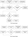
- the washing module 136 continues activating the first electrochemical cell 118 and the washing module 136 returns to determining if the tub 106 is filled. If it is determined that the tub 106 is filled to the predetermined level the washing module 136 deactivates the electrochemical cell 118. Then the washing module 136 determines if the washing cycle is complete. If it is determined that the washing cycle is not complete the washing module 136 continues the washing cycle and returns to determining if the washing cycle is complete. If it is determined that the washing cycle is complete the washing module 136 sends a completion signal to the base module 132. The washing module 136 returns to the base module 132.
- embodiments may include a treatment module 138 which begins by being initiated by the base module 132.
- the treatment module 138 activates the tub 106 drain valve.
- the treatment module 138 provides the solution from the second dosing chamber 116.
- the treatment module 138 activates the second electrochemical cell 118.
- the treatment module 138 determines if the tub 106 is emptied. If it is determined that the tub 106 is not emptied the treatment module 138 continues draining the tub 106. If it is determined that the tub 106 is emptied the treatment module 138 deactivates the electrochemical cell 118.
- the treatment module returns to the base module 132.
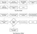
- the base module 132 sends, at step 204, the washing cycle to the washing module 136.
- the type of wash cycle selected by the user including the length in which the washing process will be performed may be sent to the washing module 136.
- the base module 132 initiates, at step 206, the washing module 136.
- the washing module 136 begins by being initiated by the base module 132.
- the washing module 136 receives the washing cycle from the base module 132.
- the washing module 136 activates the water supply.
- the washing module 136 provides the solution from the dosing chamber 116.
- the washing module 136 activates the first electrochemical cell 118.
- the maintenance module 134 may send a signal to the controller 124 which may send a signal to the plurality of sensors 128 to confirm that the sensors 128 are activated.
- the maintenance module 134 may collect data from the sensors 128 to ensure that the various sensor 128 readings are within a predetermined range to confirm that components of the water bearing electrical device 102 are working properly.
- the maintenance module 134 sends, at step 302, a status signal to the electrochemical cell 118.
- the maintenance module 134 may send a signal to the controller 124 which may send a signal to the electrochemical cell 118 to confirm that the electrochemical cell 118 is online.
- the maintenance module 134 may collect sensor 128 data from the previous operation of the electrochemical cell 118 to confirm it is functioning correctly.
- the maintenance module 134 receives, at step 308, the status signals from the power supply 126, the sensors 128, and the electrochemical cell 118.
- the controller 124 receive the status signals from the power supply 126, the sensors 128, and the electrochemical cell 118 and the controller 124 may send back to the maintenance module 134 that the power supply 126 is active, the sensors 128 are online, and that the electrochemical cell 118 is functioning properly.
- the maintenance module 134 determines, at step 310, if all of the status signals were received.
- the maintenance module 134 may determine if all of the status signals were received to confirm that the water bearing electrical device 102 may function when activated by the user.
- the notification may a visual or audio indicator, a notification on a display on the device, receiving a message through a mobile device, smart device, electronic device, etc.
- the maintenance module 134 ends, at step 314, if it is determined that all of the status signals were not received after the user has been notified. For example, if the maintenance module 134 determines all the status signals were not received the maintenance module 134 ends the process to ensure that the device is not activated when it cannot properly function. If it is determined that all of the status signals were received the maintenance module 134 returns, at step 316, to the base module 132. For example, the maintenance module 134 may send a signal to the base module 132 that the device is functioning properly, the process may continue, and the maintenance module 134 returns to the base module 132 to begin the washing cycle through the washing module 136.
- washing module 136 Functioning of the washing module 136 will now be explained with reference to FIG. 3 .
- the functions performed in the processes and methods may be implemented in differing order.
- the outlined steps and operations are only provided as examples, and some of the steps and operations may be optional, combined into fewer steps and operations, or expanded into additional steps and operations without detracting from the essence of the disclosed embodiments.
- This figure displays the washing module 136.
- the process begins with the washing module 136 being initiated, at step 400, by the base module 132.
- the washing module 136 receives, at step 402, the washing cycle from the base module 132.
- the type of wash cycle selected by the user including the length in which the washing process will be performed may be sent by the base module 132.
- the base module 132 may store the washing cycle selected by the user in a database and send the database to the washing module 136, which may include the washing cycle selected, the length of time the washing cycle takes, the amount of water required for the washing cycle, how long the electrochemical cell 118 is activated for, the number of rotations, spins, vibrations, etc. the drum will perform, etc.
- the washing module 136 activates, at step 404, the water supply.
- the washing module 136 activates the water supply by sending a signal to the controller 124 to open the valve 112 in the water supply line 110 to send the water to the electrochemical cell 118.
- the valve 112 may be opened for a predetermined amount of time depending on the washing cycle the user selected.
- the amount of water provided for the washing cycle may be dependent on sensor 128 data collected from a water pressure sensor to detect the water pressure for a period of time and once a predetermined amount of time has elapsed at a certain water pressure the valve 112 is closed.
- the washing module 136 provides, at step 406, the solution from the dosing chamber 116.
- the washing module 136 activates, at step 408, the first electrochemical cell 118.
- the washing module 136 may send a signal to the controller 124 to activate the electrochemical cell 118 by sending a specific voltage to the electrochemical cell 118, such as 1.2 volts.
- the electrochemical cell 118 may produce hydrogen peroxide as the water supply passes through the electrochemical cell 118, as well as being supplied the solution from the dosing chamber 116.
- the electrochemical cell 118 may utilize a sensor 128 to measure the correct voltage to produce hydrogen peroxide, for example, by using a hydrogen peroxide sensor 128.
- the washing module 136 feeds, at step 410, the solution from the electrochemical cell 118 to the bleaching facility 104.
- the washing module 136 feeds the hydrogen peroxide solution into the bleaching facility 104 in order to wash the textiles contained in the bleaching facility 104.
- the washing module 136 determines, at step 412, if the tub 106 is filled to the predetermined level.
- the washing module 136 may collect data from a sensor 128 located within the tub 106 to determine if the water level within the tub 106 has reached the appropriate amount to perform the washing cycle selected by the user.
- the water level may be determined by using a sensor 128 located within the line between the electrochemical cell 118 and the bleaching facility 104 to determine how long the tub 106 has been filling up with the hydrogen peroxide solution from the electrochemical cell 118.
- the washing module 136 may be continuously polling the sensor 128 located within the tub 106 to determine if the water level has reached the predetermined level. If it is determined that the tub 106 is not filled to the predetermined level the washing module 136 continues activating, at step 414, the first electrochemical cell 118 and the washing module 136 returns to determining if the tub 106 is filled.
- the washing module 136 is continuously polling the sensor 128 located within the tub 106 to determine if the water level has reached the predetermined level. If it is determined that the tub 106 is filled to the predetermined level the washing module 136 deactivates, at step 416, the electrochemical cell 118. For example, the washing module 136 may deactivate the electrochemical cell 118 by sending a signal to the controller 124 to stop supplying the voltage to the electrochemical cell 118, as well as sending a signal to the controller 124 to close the valve 112 located within the water supply line 110. Then the washing module 136 determines, at step 418, if the washing cycle is complete.
- the washing module 136 may use a predetermined amount of time for each washing cycle selected by the user as well as a predetermined number of spins, rotations, vibrations, etc. for each washing cycle and once the predetermined amount of time or spins, rotations, vibrations, etc. have been performed the washing cycle is complete.
- the washing process may include a washing cycle performed by the first electrochemical cell 118 and a separate rinsing cycle that may be performed by the second electrochemical cell 118. For example, once the washing cycle is complete the rinsing cycle is immediately initiated and the water from the washing cycle is treated by the second electrochemical cell 118 to be used in the rinsing cycle to further treat the textiles located in the drum 108.
- the washing cycle may use the first electrochemical cell 118 to produce hydrogen peroxide to treat the textiles and the rinsing cycle may use the second electrochemical cell 118 to produce hydroxide ions to treat the water used in the washing cycle and use the treated water in a rinsing or refreshing cycle for the textiles located in the drum 108.
- the two electrochemical cells 118 may have different types of electrodes, such as nickel, stainless steel, platinum, graphite, diamond, etc. The different electrodes may allow the electrochemical cells 118 to better produce hydrogen peroxide, hydrogen ions, hydroxide ions, etc.
- the first electrochemical cell 118 may have nickel electrodes to better produce hydrogen peroxide for the washing cycle and the second electrochemical cell 118 may have diamond electrodes to better produce hydroxide ions.
- the first and second electrochemical cells 118 may be used depending on the electrodes that are contained within the electrochemical cell 118 for each different type of wash process selected by the user.
- the washing module 136 may utilize a database that contains the various wash processes that a user may select and the corresponding components that may be used and data files containing the instructions to be sent to the controller 124 to activate each of the components and how long to activate each of the components.
- the database would have a data file containing instructions to activate the first electrochemical cell 118, by supply 1.2 volts to the nickel electrodes of the first electrochemical cell 118, to produce a hydrogen peroxide water solution that would be contained in 50% of the water used in the washing cycle and the textiles will be rotated for 20 minutes, etc.
- the database used by the washing module 136 may include a plurality of electrochemical cells 118 that contain different electrodes, different voltages to apply to each of the electrochemical cells 118, how long to apply the voltages to the electrochemical cells, the product generated by the electrochemical cell 118 such as hydrogen peroxide, hydrogen ions, hydroxide ions, etc.
- the database used by the washing module 136 may contain the different shapes of the electrodes, the distance between each electrode, the rate of production for the product generated by different times and different voltages, etc. If it is determined that the washing cycle is not complete the washing module 136 continues, at step 420, the washing cycle and returns to determining if the washing cycle is complete.
- the washing module 136 sends, at step 422, a completion signal to the base module 132.
- a completion signal For example, the washing module 136 sends a signal to the base module 132 to inform the base module 132 that the washing cycle selected by the user is complete.
- the washing module 136 returns, at step 424, to the base module 132.
- This figure displays the treatment module 138.
- the process begins with the treatment module 138 being initiated, at step 500, by the base module 132.
- the treatment module 138 activates, at step 502, the tub 106 drain valve.
- the treatment module 138 activates the tub 106 drain valve to drain or empty the wastewater located in a drain line connected to a drain entrance at the bottom of the tub 106.
- the treatment module 138 provides, at step 504, the solution from the second dosing chamber 116.
- the anode material When connected to an external power source, the anode material will electrochemically corrode due to oxidation, while the cathode will be subjected to passivation. It consists of pairs of conductive metal plates in parallel, which act as monopolar electrodes. It furthermore requires a direct current power source, a resistance box to regulate the current density and a multimeter to read the current values.
- the conductive metal plates are commonly known as sacrificial electrodes.
- the sacrificial anode lowers the dissolution potential of the anode and minimizes the passivation of the cathode.
- the sacrificial anodes and cathodes can be of the same or of different materials.
- the arrangement of monopolar electrodes with cells in series is electrically similar to a single cell with many electrodes and interconnections.
- series cell arrangement a higher potential difference is required for a given current to flow because the cells connected in series have higher resistance. The same current would, however, flow through all the electrodes.
- parallel or bipolar arrangement the electric current is divided between all the electrodes in relation to the resistance of the individual cells, and each face on the electrode has a different polarity.
- the positive side undergoes anodic reactions, while on the negative side, cathodic reactions are encountered.
- Consumable metal plates such as iron or aluminum, are usually used as sacrificial electrodes to continuously produce ions in the water.
- the released ions neutralize the charges of the particles and thereby initiate coagulation.
- the released ions remove undesirable contaminants either by chemical reaction and precipitation, or by causing the colloidal materials to coalesce, which can then be removed by flotation.
- water containing colloidal particulates, oils, or other contaminants move through the applied electric field, there may be ionization, electrolysis, hydrolysis, and free-radical formation which can alter the physical and chemical properties of water and contaminants.
- the reactive and excited state causes contaminants to be released from the water and destroyed or made less soluble.
- the first electrochemical cell 118 may be used to treat the wastewater generated by the washing process.
- the first electrochemical cell 118 may be a multi-stage electrochemical cell 118 in which the cell is activated at different stages of wash cycle to perform different functions, such as during the washing process the first electrochemical cell 118 may be activated to produce hydrogen peroxide to clean the textiles located in the drum 108, and then during the wastewater treatment process the first electrochemical cell 118 may be activated to use the hydrogen ions or hydroxide ions generated to treat the wastewater depending on the pH balance of the wastewater.
- the wastewater may be drained into a reserve tank that includes a plurality of sensors 128, such as a pH sensor 128, and the treatment module 138 may receive the pH sensor 128 data from the reserve tank and compare the data to a database that contains the pH adjustment to treat the wastewater.
- the pH heavy metals and other toxic metals can be removed from the water. If the pH is raised, by raising the amount of negative hydroxide ions, the positively charged metal ions will form bonds with the negatively charged hydroxide ions and creates a dense, insoluble, metal particle that can be filtered out manually using the filters 122, such as by a filter press.
- the pH of water can be used to kill off bacteria in wastewater in addition to the treatment mentioned above. Most organic matter and bacteria that is familiar and contact daily with are best suited to a neutral or slightly basic environment. At an acidic pH the excess hydrogen ions begin to form bonds with and break down the cell, slowing their growth or killing them outright.
- the treatment module 138 may raise the pH level an acidic pH level to treat the wastewater, lower the pH level of a basic pH level to kill of bacteria, contaminants, etc. and then raise the pH level back up, etc. to treat the wastewater using the hydrogen ions and hydroxide ions generated by the first electrochemical cell 118.
- the treatment module 138 determines, at step 508, if the tub 106 is emptied.
- the treatment module 138 may be used to detect the water level of the tub 106 and if the collected data informs the treatment module 138 that the water level is below the sensor 128, for example reading no more water, then the tub 106 is emptied. If it is determined that the tub 106 is not emptied the treatment module 138 continues, at step 510, draining the tub 106. For example, the treatment module 138 is continuously polling the sensor 128 located at the bottom of the tub 106 to determine if the tub 106 has been emptied. If it is determined that the tub 106 is emptied the treatment module 138 deactivates, at step 512, the electrochemical cell 118.
- the treatment module 138 deactivates the electrochemical cell 118 by no longer supplying the electrochemical cell 118 with a current.
- the treated wastewater may be disposed of, either by a drainage pipe or storage tank, may be reused by placing the treated wastewater in a storage tank that may be used for another wash process.
- the treatment module returns, at step 514, to the base module 132.
Landscapes
- Chemical & Material Sciences (AREA)
- Engineering & Computer Science (AREA)
- Chemical Kinetics & Catalysis (AREA)
- Electrochemistry (AREA)
- Life Sciences & Earth Sciences (AREA)
- Hydrology & Water Resources (AREA)
- Environmental & Geological Engineering (AREA)
- Water Supply & Treatment (AREA)
- Organic Chemistry (AREA)
- General Chemical & Material Sciences (AREA)
- Textile Engineering (AREA)
- Water Treatment By Electricity Or Magnetism (AREA)
Abstract
The present disclosure provides a method for a multistage electrode-based water treatment in which a water bearing electrical device is tested for performance. Then water is supplied to the device and a current is supplied to the first electrochemical cell as well as a solution, possibly a detergent. Then the electrolyte solution generated from the first electrochemical cell is fed to a bleaching facility and the wash process is completed. The bleaching facility is then drained, and a current is applied to a second electrochemical cell to treat the wastewater generated during the wash process.
Description
- The present disclosure is generally related to a multistage electrode-based water treatment.
- Most clothes washers and dishwashers use detergents to clean the desired objects (clothing or cookware). Various formulations of detergents have been introduced that provide excellent cleaning in either type of machine. For example, clothes washers often use a surfactant such as a linear alkylbenzene sulfonates, usually along with water softeners, bleaches, enzymes, etc. Dishwashers also use surfactants, water softeners, bleaches, enzymes, and other ingredients. Detergents have become substantially more environmentally sensitive Over the years in terms of wastewater processing concerns of the various ingredients. However, use of detergents generally requires use of rinse cycles, which in turn requires that additional water and energy be used by the machine. Further, additional wastewater is generated during such a rinse cycle, requiring additional treatment in a septic or sewage system. In order to avoid or reduce use of detergents, detergent less ionic washing has been proposed in clothing and dishwashers. For example, a number of such ionic washers disclose systems wherein alkaline water is produced for detergent less washing in various embodiments of electrolysis devices. However, currently household appliances as well as professional used appliances for washing or cleaning textiles do not utilize a multi-stage water treatment device in which the water is first treated to assist in cleaning the textiles and the second stage is used for treating the wastewater.
- Also, such systems do not provide a check of the overall system or device prior to using the appliance. In general, a washing machine (usually, a drum washing machine) is an apparatus, which includes a tub to contain water (wash water or rinse water), a cylindrical drum rotatably installed to receive laundry, and a motor generating driving force to rotate the drum and achieves washing of the laundry through tumbling of the laundry along the inner wall of the drum when the cylindrical drum is rotated. Such a washing machine performs washing of laundry through a series of cycles, i.e., a washing cycle to remove contaminants from the laundry using water dissolving a detergent (concretely, wash water), a rinsing cycle to remove foams and residues of the detergent from the laundry using water not dissolving the detergent (concretely, rinse water), and a spin-drying cycle to dehydrate the laundry at a high speed. When the laundry is washed through this series of cycles, contaminants or lime scales are deposited on the rear surface of the drum as time goes by. The contaminants or the lime scales cause propagation of microorganisms (bacteria) throughout the tub, and further generate surface deposits (flock) causing decay, thereby bringing about generation of mold. The mold is a source of odor generation due to metabolic products thereof or is attached to laundry while subsequent washing of laundry is performed, thus contaminating the laundry.
- Lastly, most appliances with an ability to treat the water supply for a washing process do not provide a solution for the wastewater generated during the wash process. Household cleaning processes like laundry, dishes etc., require large amounts of water. The wastewater generated in-home from washing and rinsing laundry is generally referred to as greywater. It would be a great benefit if it were possible to reduce the amount of greywater that is produced by households. One possible way of achieving this is to treat the greywater so it can be reused, notably in cleaning processes. In order to reuse household grey water for cleaning processes it is essential to remove all the particulate matter and the detergents. A commercially available front loading washing machine typically uses approximately 50 liters of water for a normal full wash cycle. A top loading washing machine typically requires about 200 liters of water. Depending on the number of rinse steps, 25% or more of this volume of water is required for the main wash, while 65% or more is used for the consecutive rinse cycles. This is an enormous amount of grey water for businesses and consumers, who may wish to reduce their environmental impact, to produce on a regular basis. There is therefore a need to reduce the environmental burden of water-bearing appliance wastewater. Thus, there is a need in the prior art to provide a method for a multistage electrode-based water treatment.
-
-
FIG. 1 : Illustrates a multistage electrode-based water treatment, according to an embodiment. -
FIG. 2 : Illustrates a Base Module, according to an embodiment. -
FIG. 3 : Illustrates a Maintenance Module, according to an embodiment. -
FIG. 4 : Illustrates a Washing Module, according to an embodiment. -
FIG. 5 : Illustrates a Treatment Module, according to an embodiment. - Embodiments of the present disclosure will be described more fully hereinafter with reference to the accompanying drawings in which like numerals represent like elements throughout the several figures, and in which example embodiments are shown. Embodiments of the claims may, however, be embodied in many different forms and should not be construed as limited to the embodiments set forth herein. The examples set forth herein are non-limiting examples and are merely examples among other possible examples.
- This is a method for a multistage electrode-based water treatment. This method comprises of a water bearing
electrical device 102 in which cleaning is to be achieved using a bleaching agent, and a water-bearing electrical device which carries out cleaning using a bleaching agent, i.e., hydrogen peroxide produced from electrolysis, such as by a washing machine, a dishwasher, a type of household or professional disinfector appliance, etc. The water bearingelectrical device 102 may include ableaching facility 104 and anelectrochemical cell 118 with a cathode arranged in a cathode chamber and an anode arranged in an anode chamber, which are spatially separated, having the following steps during a cleaning program, which includes a washing process and has several rinsing processes. First, providing a solution in the electrochemical cell which comprises water and an electrolyte. Second, applying a current to the electrochemical cell and simultaneously introducing an oxygen-containing gas to produce a bleach in a catholyte. Third, feeding the catholyte from the electrochemical cell into thebleaching facility 104 before and/or during the washing process. In the first step, a water and electrolyte containing solution is provided in theelectrochemical cell 118, wherein the solution can be arranged in theelectrochemical cell 118 or passed through it. The electrolyte can comprise or consist of an inorganic salt and/or a builder. The inorganic salt is preferably sodium sulfate and/or sodium hydrogen carbonate. In a preferred embodiment, the builder has one or more components selected from the group consisting of citric acid, lactic acid, phosphonate, polycarboxylic acid, aminocarboxylic acid, polyacrylic acid and/or their salts. Alternatively, the builder preferably consists of one or more of these components. In the second step, if the oxygen-containing gas is supplied to theelectrochemical cell 118, which preferably has a gas diffusion electrode in the cathode space, and current is applied to it, an electrolysis starts in which a bleaching agent, such as hydrogen peroxide, is formed. Due to the spatial separation of the cathode and anode compartments, the anolyte and the catholyte are produced separately from one another. The pH of the catholyte is shifted into the alkaline pH range, while a pH value of the anolyte is shifted into the acidic pH range. If the anode compartment and the cathode compartment were not separated, the catholyte and the anolyte would at least partially neutralize each other, which has proven to be disadvantageous. A pH of the catholyte is preferably in the range from 9 to 14, more preferably 10 to 12. In the third step, only the catholyte is fed to thebleaching facility 104. In other words, the catholyte is fed to thebleaching facility 104 without an anolyte produced in the second step. The catholyte is anolyte-free. During the washing process, items to be cleaned or thebleaching facility 104 itself is washed with the bleaching agent produced, such as hydrogen peroxide produced from electrolysis, and, if necessary, other ingredients of the solution in order to clean it. During the one or more rinsing processes, the items to be cleaned or thebleaching facility 104 itself is rinsed with water in order to rinse the solution out of thebleaching facility 104 and possibly the items to be cleaned. In some embodiments, the method furthermore has a step of feeding the anolyte produced in the second step from theelectrochemical cell 118 into thebleaching facility 104 after a washing process has been carried out. The anolyte produced in the second step is preferably fed to thebleaching facility 104 before and/or during the execution of a rinsing process from theelectrochemical cell 118. By inserting the acidic anolyte solution into one of the wash cycles, any calcium deposits that may have formed in the water-conducting electrical device and/or on the items to be cleaned can be dissolved again. Hygiene is increased, since both alkaline and acidic pH values are run through in the water-bearing electrical device during a washing and rinsing cycle. The anolyte is therefore used sensibly. In some embodiments, the bleaching agent may refer to a chemical compound, may be hydrogen peroxide produced by an electrochemical process, such as by anelectrochemical cell 118, may be an anolyte or catholyte resulting from or generated as an intermediary product during an electrochemical process. In some embodiments, the bleaching agent may remove dyes, contaminants, pathogens, etc. from textiles, fabrics, materials, surfaces, fluids, etc. For instance, a water bearingelectrical device 102 such as a water bearingelectrical device 102 ofEP3865614A1 . Further, embodiments may include ableaching facility 104 which may contain atub 106 and adrum 108 contained within thetub 106. Thebleaching facility 104 may receive the catholyte produced from the firstelectrochemical cell 118 before and/or during a washing process via a supply line to clean the items stored in thedrum 108. In some embodiments, after the washing process the anolyte produced by the secondelectrochemical cell 118 may be fed to thebleaching facility 104 before and/or during the execution of a rinsing process from the secondelectrochemical cell 118. By inserting the acidic anolyte solution into one of the wash cycles, any calcium deposits that may have formed in the water-conducting electrical device and/or on the items to be cleaned can be dissolved again. Hygiene is increased, since both alkaline and acidic pH values are run through in the water-bearing electrical device during a washing and rinsing cycle. For instance, ableaching facility 104 such as ableaching facility 104 ofEP3865614A1 . Further, embodiments may include atub 106 that seals in the water of the water bearingelectrical device 102 and may vibrate, shake, rotate, etc. by a motor and a counterweight in order to clean, wash, rinse, etc. the items contained in thedrum 108 which may be contained within thetub 106. In some embodiments, thebleaching facility 104 may contain atub 106 anddrum 108, such as a washing machine. In some embodiments, thetub 106 may include a drain, drain line, drain pump, and drain valve to dispose of the wastewater created during the wash process. In some embodiments, thetub 106 may be drained or emptied of the wastewater by activating a drain valve located in a drain line connected to a drain entrance at the bottom of thetub 106. In some embodiments, the bleaching facility may only contain atub 106 or water sealeddrum 108, such as a dishwasher. In some embodiments, the bleaching facility may be used for a household or professional use disinfector appliance that may or may not include atub 106 ordrum 108. For instance, atub 106 such as atub 106 ofUS6841058B2 . Further, embodiments may include adrum 108 that is contained within thetub 106 and is where the items to be cleaned are placed. Thedrum 108 may include sides that perforated with holes to allow water to enter and exit upon spinning thedrum 108. For instance, adrum 108 such as adrum 108 ofUS6841058B2 . Further, embodiments may include awater supply line 110 that connects to theelectrochemical cell 118 to supply the water for the washing process. Thewater supply line 110 may include avalve 112 that may be opened or closed based on the control signals received from thecontroller 130 to feed the water to theelectrochemical cell 118 for the wash cycle. Thewater supply line 110 may be connected to a water source, such as a water line for a household, building, or dwelling. In some embodiments, thewater supply line 110 may be replaced with a water tank located within the water bearingelectrical device 102 to supply the water to theelectrochemical cell 118. In some embodiments, thewater supply line 110 may include a pump, a pressurized source, etc. to move the water through thewater supply line 110. For instance, awater supply line 110 such as a feed supply ofUS7950254B2 . Further, embodiments may include avalve 112 for thewater supply line 110 that may be opened or closed based on the control signals received from thecontroller 130 to feed the water to theelectrochemical cell 118 for the wash cycle. In some embodiments, thevalve 112 may be used to control the supply of water from a water tank or another source of water for the washing process or cycle. Further, embodiments may include agas pump 114 which connects to the cathode through a gas supply line to supply air or oxygen to the cathode chamber. Thegas pump 114 supplies air or oxygen as an oxygen-containing gas via a gas supply line to the cathode chamber and a current is applied to theelectrochemical cell 118. Applying a current to theelectrochemical cell 118 at the same time introducing an oxygen-containing gas, such as air, into the cathode space by activating thegas pump 114 generates hydrogen peroxide in the aqueous electrolyte-containing solution. For instance, agas pump 114 such as an oxygen supply line ofJP2005146344A dosing chamber 116 which is designed to meter an electrolyte, for example an electrolyte-containing solution, such as a salt-containing solution, and possibly a detergent into theelectrochemical cell 118 by means of a metering pump. When theelectrochemical cell 118 is supplied with water in a predetermined quantity, the electrolyte, such as a solution containing salt, and possibly a detergent is metered from thedosing chamber 116 into theelectrochemical cell 118 via the metering pump. In some embodiments, thedosing chamber 116 may provide the electrolyte to theelectrochemical cell 118 through a pipe, hose, tubing, etc. In some embodiments, thedosing chamber 116 may be replaced with a dosing pump, metering pump, etc. to provide the electrolyte to theelectrochemical cell 118. In some embodiments, the electrolytes may include sodium, chloride, potassium, magnesium, calcium, etc. For instance, adosing chamber 116 such as adosing chamber 116 ofEP2798995B1 . Further, embodiments may include anelectrochemical cell 118 with a cathode compartment and an anode compartment, that provides an aqueous electrolyte-containing solution in theelectrochemical cell 118 and applies a current to theelectrochemical cell 118 and simultaneously introduces an oxygen-containing gas to generate hydrogen peroxide in the aqueous electrolyte-containing solution. Then the electroylated solution is fed from theelectrochemical cell 118 into the bleaching device and a bleach activator is fed into theelectrochemical cell 118 and/or thebleaching facility 104. Theelectrochemical cell 118 is designed to produce a hydrogen peroxide-containing bleaching agent using the electrolyte, water, air and electric current. If theelectrochemical cell 118 has the electrolyte, water and air and an electric current flow, water is oxidized at an anode of the electrochemical cell, with protons being formed. At the same time, the oxygen contained in the air is reduced at a cathode of theelectrochemical cell 118, in particular a gas diffusion electrode. The protons are used up, for example, the protons combine with the electrons to form hydrogen, and hydrogen peroxide is produced. The cathode is preferably designed as an oxygen diffusion electrode. The anode can be a dimensionally stable anode, a mixed oxide electrode or a boron-doped diamond electrode. The reaction product of electrolysis is a hydrogen peroxide solution. An anode compartment in which the anode is located and a cathode compartment in which the cathode is located are preferred, for example, through a membrane such as a cation exchange membrane spatially separated, so that an alkaline hydrogen peroxide solution is preferably produced. The electrode, such as diamond electrode, of the reactor is preferably boron- or nitrogen-doped. One or more of the electrodes may be a boron-doped diamond electrode, such as diamond electrodes which have a possibly doped diamond layer applied to a carrier material. The diamond electrode may function as an anode or a cathode in the process, the reactor having a counter electrode of a suitable material, such as steel, which may also form the reactor itself. It is also possible that the reactor has two diamond electrodes which function as anode and cathode. The reactor therefore constitutes an electrolyzer. It may also be designed as an electrolyzer having a membrane which spatially separates the anode and the cathode, so that products and/or intermediates formed on electrolysis on a diffusion from the cathode to the anode space and/or prevented vice versa. For instance, anelectrochemical cell 118 such as anelectrochemical cell 118 ofEP3865614A1 ,US6132572A ,US9994463B2 JP2005146344A heating system 120 which may be used to heat the water supply to a desired temperature for a washing process. The water bearing electrical appliance may include a built in heater to heat the water supply. In some embodiments, thewater supply line 110 may include a hot water supply line to provide heated water to the cleaning process. In some embodiments, theheating system 120 may include a container with an inlet channel and an outlet channel and in the container two spaced plates which act as electrodes and each have an electrical connection for connection to an electrical voltage source for generating a current flow I through the water between the plates, with at least one plate being movably mounted to the distance between the plates and thereby to change the volume of water provided between the plates. The plates may have a large distance from each other. A movable plate is guided in the container by means of a lever mechanism. A drive means serves to drive the lever mechanism to move the plate in order to change the parallel distance of the plate to the fixed plate. A control device is designed to switch the appropriate AC voltage to the plates and to activate the drive means in order to set the distance between the plates. The conductance of the liquid located in the container can be detected with the detection means and fed to the control device. Based on the detected conductance and the specified requirements for the water heating, the control device can activate the drive means in order to set the distance in such a way that an electrical current flow is set, which leads to the desired heating of the water. Theheating system 120 is designed as a continuous-flow heater, it can also be designed as a boiler. The current is an alternating current of the same frequency due to the alternating voltage applied to the plates. Further, embodiments may include a plurality offilters 122 to capture unwanted elements from entering or exiting the water bearingelectrical device 102, such as dirt, lint, harmful contaminants, etc. Thefilters 122 may be located within thewater supply line 110 and/or at the drainage component of the water bearingelectrical device 102. For instance, afilter 122 such as afilter 122 ofUS9994463B2 controller 124 which is a computing device comprised of a processor for performing computations and communicates with amemory 130 for storing data. Thecontroller 124 is in communication with a plurality of components of the water bearingelectrical device 102 and may further be allowed to control the functions of the water bearingelectrical device 102. Thecontroller 124 may be a commercially available central processing unit (CPU) or graphical processing unit (GPU) or may be a proprietary, purpose-build design. More than onecontroller 124 may operate in tandem and may be of different types, such as a CPU and a GPU. A GPU is not restricted to only processing graphics or image data and may be used for other computations. Further, embodiments may include apower supply 126 which may be a hardware component that supplies power to the water bearingelectrical device 102. It receives power from an electrical outlet and converts the current from AC, alternating current, to DC, direct current, or may supply the alternating current, and may regulate the voltage to an adequate amount. Thepower supply 126 may be wired, wireless, such as through a battery. Thepower supply 126 may supply a current to the water bearingelectrical device 102,electrochemical cell 118,gas pump 114,heating system 120,sensors 128, etc. collectively or individually. Further, embodiments may include asensor 128 which is a measurement tool for monitoring a characteristic or metric associated with the water bearingelectrical device 102. Asensor 128 may be discrete or part of an array or assembly. Asensor 128 may be a pH sensor which may be used to accurately measure acidity and alkalinity in water and other liquid substances. Asensor 128 may be a sensor to detect contamination within the water, either entering or exiting the water bearingelectrical device 102, such as chemical sensors, electrochemical piezoelectric sensors, functional DNA biosensors, TOC sensors, etc. One or more of thesensors 128 may include temperature sensors, rotor position sensors, water level sensors, dirt sensors, photoelectric sensors, pressure sensors, vibration sensors, water flow sensors, proximity sensors, humidity sensors, any combination thereof, etc. Thesensors 128 may be integrated into the operation of the water bearingelectrical device 102 or may monitor the status of the device. In some embodiments, the data collected by thesensors 128 may be in real-time or may need to be analyzed further to produce findings. For instance, asensor 128 such as asensor 128 ofUS9702074B2 US11147650B2 EP2397062B1 . Further, embodiments may include amemory 130 such as the electronic circuitry within a computing device that temporarily stores data for usage by thecontroller 124. Thememory 130 may additionally comprise persistent data storage for storing data used by thecontroller 124. Thememory 130 may be integrated into acontroller 124 or may be a discrete component. Thememory 130 may be integrated into a circuit, such as soldered on component of a single board computer (SBC) or may a removable component such as a discrete dynamic random-access memory (DRAM) stick, secure digital (SD) card, flash drive, solid state drive (SSD), magnetic hard disk drive (SSD), etc. In some embodiments,memory 130 may be part of acontroller 124. Further, embodiments may include abase module 132 which begins with the user selecting the washing cycle. Thebase module 132 initiates themaintenance module 134. Thebase module 132 sends the washing cycle to thewashing module 136. Thebase module 132 initiates thewashing module 136. Thebase module 132 receives the completion signal from thewashing module 136. Thebase module 132 initiates thetreatment module 138. Further, embodiments may include amaintenance module 134 which begins by being initiated by thebase module 132. Themaintenance module 134 sends a status signal to thepower supply 126. Themaintenance module 134 sends a status signal to thesensors 128. Themaintenance module 134 sends a status signal to theelectrochemical cell 118. Themaintenance module 134 receives the status signals from thepower supply 126, thesensors 128, and theelectrochemical cell 118. Themaintenance module 134 determines if all of the status signals were received. If it is determined that all of the status signals were not received themaintenance module 134 notifies the user. Themaintenance module 134 ends if it is determined that all of the status signals were not received after the user has been notified. If it is determined that all of the status signals were received themaintenance module 134 returns to thebase module 132. Further, embodiments may include awashing module 136 which begins by being initiated by thebase module 132. Thewashing module 136 receives the washing cycle from thebase module 132. Thewashing module 136 activates the water supply. Thewashing module 136 provides the solution from thedosing chamber 116. Thewashing module 136 activates the firstelectrochemical cell 118. Thewashing module 136 feeds the solution from theelectrochemical cell 118 to thebleaching facility 104. Thewashing module 136 determines if thetub 106 is filled to the predetermined level. If it is determined that thetub 106 is not filled to the predetermined level thewashing module 136 continues activating the firstelectrochemical cell 118 and thewashing module 136 returns to determining if thetub 106 is filled. If it is determined that thetub 106 is filled to the predetermined level thewashing module 136 deactivates theelectrochemical cell 118. Then thewashing module 136 determines if the washing cycle is complete. If it is determined that the washing cycle is not complete thewashing module 136 continues the washing cycle and returns to determining if the washing cycle is complete. If it is determined that the washing cycle is complete thewashing module 136 sends a completion signal to thebase module 132. Thewashing module 136 returns to thebase module 132. Further, embodiments may include atreatment module 138 which begins by being initiated by thebase module 132. Thetreatment module 138 activates thetub 106 drain valve. Thetreatment module 138 provides the solution from thesecond dosing chamber 116. Thetreatment module 138 activates the secondelectrochemical cell 118. Thetreatment module 138 determines if thetub 106 is emptied. If it is determined that thetub 106 is not emptied thetreatment module 138 continues draining thetub 106. If it is determined that thetub 106 is emptied thetreatment module 138 deactivates theelectrochemical cell 118. The treatment module returns to thebase module 132. - Functioning of the
base module 132 will now be explained with reference toFIG. 2 . One skilled in the art will appreciate that, for this and other processes and methods disclosed herein, the functions performed in the processes and methods may be implemented in differing order. Furthermore, the outlined steps and operations are only provided as examples, and some of the steps and operations may be optional, combined into fewer steps and operations, or expanded into additional steps and operations without detracting from the essence of the disclosed embodiments. - This figure displays the
base module 132. The process begins with the user selecting, at step 200, the washing cycle. For example, the user may select the type of wash process the water bearingelectrical device 102 will perform, such as a normal wash, heavy duty, delicate, etc. Each wash process may have different types of motions performed by thedrum 108, such as a different number of spins, rotations, vibrations within thebleaching facility 104. Each wash process may be performed for different periods of time to effectively wash the textiles located in thebleaching facility 104 depending on the wash cycle selected. In some embodiments, the predetermined time for the wash cycle selected may be sent to thewashing module 134. Thebase module 132 initiates, atstep 202, themaintenance module 134. For example, themaintenance module 134 may begin by being initiated by thebase module 132. Themaintenance module 134 sends a status signal to thepower supply 126. Themaintenance module 134 sends a status signal to thesensors 128. Themaintenance module 134 sends a status signal to theelectrochemical cell 118. Themaintenance module 134 receives the status signals from thepower supply 126, thesensors 128, and theelectrochemical cell 118. Themaintenance module 134 determines if all of the status signals were received. If it is determined that all of the status signals were not received themaintenance module 134 notifies the user. Themaintenance module 134 ends if it is determined that all of the status signals were not received after the user has been notified. If it is determined that all of the status signals were received themaintenance module 134 returns to thebase module 132. Thebase module 132 sends, atstep 204, the washing cycle to thewashing module 136. For example, the type of wash cycle selected by the user, including the length in which the washing process will be performed may be sent to thewashing module 136. Thebase module 132 initiates, atstep 206, thewashing module 136. For example, thewashing module 136 begins by being initiated by thebase module 132. Thewashing module 136 receives the washing cycle from thebase module 132. Thewashing module 136 activates the water supply. Thewashing module 136 provides the solution from thedosing chamber 116. Thewashing module 136 activates the firstelectrochemical cell 118. Thewashing module 136 feeds the solution from theelectrochemical cell 118 to thebleaching facility 104. Thewashing module 136 determines if thetub 106 is filled to the predetermined level. If it is determined that thetub 106 is not filled to the predetermined level thewashing module 136 continues activating the firstelectrochemical cell 118 and thewashing module 136 returns to determining if thetub 106 is filled. If it is determined that thetub 106 is filled to the predetermined level thewashing module 136 deactivates theelectrochemical cell 118. Then thewashing module 136 determines if the washing cycle is complete. If it is determined that the washing cycle is not complete thewashing module 136 continues the washing cycle and returns to determining if the washing cycle is complete. If it is determined that the washing cycle is complete thewashing module 136 sends a completion signal to thebase module 132. Thewashing module 136 returns to thebase module 132. Thebase module 132 receives, atstep 208, the completion signal from thewashing module 136. For example, thebase module 132 receives a signal from thewashing module 136 that the wash process is complete. In some embodiments, the wash process may be completed when a timer that is set to the length of the wash cycle selected is completed. Thebase module 132 initiates, atstep 210, thetreatment module 138. For example, thetreatment module 138 begins by being initiated by thebase module 132. Thetreatment module 138 activates thetub 106 drain valve. Thetreatment module 138 provides the solution from thesecond dosing chamber 116. Thetreatment module 138 activates the secondelectrochemical cell 118. Thetreatment module 138 determines if thetub 106 is emptied. If it is determined that thetub 106 is not emptied thetreatment module 138 continues draining thetub 106. If it is determined that thetub 106 is emptied thetreatment module 138 deactivates theelectrochemical cell 118. The treatment module returns to thebase module 132. Thebase module 132 ends, atstep 212, once the washing cycle is complete and the wastewater has been treated. - Functioning of the
maintenance module 134 will now be explained with reference toFIG. 2 . One skilled in the art will appreciate that, for this and other processes and methods disclosed herein, the functions performed in the processes and methods may be implemented in differing order. Furthermore, the outlined steps and operations are only provided as examples, and some of the steps and operations may be optional, combined into fewer steps and operations, or expanded into additional steps and operations without detracting from the essence of the disclosed embodiments. - This figure displays the
maintenance module 134. The process begins with themaintenance module 134 being initiated, atstep 300, by thebase module 132. Themaintenance module 134 sends, at step 302, a status signal to thepower supply 126. For example, themaintenance module 134 may send a signal to thecontroller 124 which may send a signal to thepower supply 126 to confirm that thepower supply 126 is activated. In some embodiments, thecontroller 124 may send a signal to a plurality of components of the water bearingelectrical device 102 to confirm that the various components are receiving power. Themaintenance module 134 sends, at step 302, a status signal to thesensors 128. For example, themaintenance module 134 may send a signal to thecontroller 124 which may send a signal to the plurality ofsensors 128 to confirm that thesensors 128 are activated. In some embodiments, themaintenance module 134 may collect data from thesensors 128 to ensure that thevarious sensor 128 readings are within a predetermined range to confirm that components of the water bearingelectrical device 102 are working properly. Themaintenance module 134 sends, at step 302, a status signal to theelectrochemical cell 118. For example, themaintenance module 134 may send a signal to thecontroller 124 which may send a signal to theelectrochemical cell 118 to confirm that theelectrochemical cell 118 is online. In some embodiments, themaintenance module 134 may collectsensor 128 data from the previous operation of theelectrochemical cell 118 to confirm it is functioning correctly. Themaintenance module 134 receives, at step 308, the status signals from thepower supply 126, thesensors 128, and theelectrochemical cell 118. For example, thecontroller 124 receive the status signals from thepower supply 126, thesensors 128, and theelectrochemical cell 118 and thecontroller 124 may send back to themaintenance module 134 that thepower supply 126 is active, thesensors 128 are online, and that theelectrochemical cell 118 is functioning properly. Themaintenance module 134 determines, atstep 310, if all of the status signals were received. For example, themaintenance module 134 may determine if all of the status signals were received to confirm that the water bearingelectrical device 102 may function when activated by the user. In some embodiments, there may be a database containing the statuses of all the components of the device and their current statuses which may be used for diagnostic purposes. If it is determined that all of the status signals were not received themaintenance module 134 notifies, at step 312, the user. For example, the user may be notified if a component of the device is not functioning properly, such as a power light being turned off to inform the user of thepower supply 126 not being active, a beep or noise indicating if thesensors 128 orelectrochemical cell 118 are not functioning properly. In some embodiments, the notification may a visual or audio indicator, a notification on a display on the device, receiving a message through a mobile device, smart device, electronic device, etc. Themaintenance module 134 ends, atstep 314, if it is determined that all of the status signals were not received after the user has been notified. For example, if themaintenance module 134 determines all the status signals were not received themaintenance module 134 ends the process to ensure that the device is not activated when it cannot properly function. If it is determined that all of the status signals were received themaintenance module 134 returns, atstep 316, to thebase module 132. For example, themaintenance module 134 may send a signal to thebase module 132 that the device is functioning properly, the process may continue, and themaintenance module 134 returns to thebase module 132 to begin the washing cycle through thewashing module 136. - Functioning of the
washing module 136 will now be explained with reference toFIG. 3 . One skilled in the art will appreciate that, for this and other processes and methods disclosed herein, the functions performed in the processes and methods may be implemented in differing order. Furthermore, the outlined steps and operations are only provided as examples, and some of the steps and operations may be optional, combined into fewer steps and operations, or expanded into additional steps and operations without detracting from the essence of the disclosed embodiments. - This figure displays the
washing module 136. The process begins with thewashing module 136 being initiated, atstep 400, by thebase module 132. Thewashing module 136 receives, atstep 402, the washing cycle from thebase module 132. For example, the type of wash cycle selected by the user, including the length in which the washing process will be performed may be sent by thebase module 132. In some embodiments, thebase module 132 may store the washing cycle selected by the user in a database and send the database to thewashing module 136, which may include the washing cycle selected, the length of time the washing cycle takes, the amount of water required for the washing cycle, how long theelectrochemical cell 118 is activated for, the number of rotations, spins, vibrations, etc. the drum will perform, etc. Thewashing module 136 activates, atstep 404, the water supply. For example, thewashing module 136 activates the water supply by sending a signal to thecontroller 124 to open thevalve 112 in thewater supply line 110 to send the water to theelectrochemical cell 118. In some embodiments, thevalve 112 may be opened for a predetermined amount of time depending on the washing cycle the user selected. In some embodiments, the amount of water provided for the washing cycle may be dependent onsensor 128 data collected from a water pressure sensor to detect the water pressure for a period of time and once a predetermined amount of time has elapsed at a certain water pressure thevalve 112 is closed. Thewashing module 136 provides, atstep 406, the solution from thedosing chamber 116. For example, when theelectrochemical cell 118 is supplied with water in a predetermined quantity, the solution containing salt and possibly a detergent is metered from thedosing chamber 116 into theelectrochemical cell 118 via the metering pump. Thewashing module 136 activates, atstep 408, the firstelectrochemical cell 118. For example, thewashing module 136 may send a signal to thecontroller 124 to activate theelectrochemical cell 118 by sending a specific voltage to theelectrochemical cell 118, such as 1.2 volts. Theelectrochemical cell 118 may produce hydrogen peroxide as the water supply passes through theelectrochemical cell 118, as well as being supplied the solution from thedosing chamber 116. In some embodiments, theelectrochemical cell 118 may utilize asensor 128 to measure the correct voltage to produce hydrogen peroxide, for example, by using ahydrogen peroxide sensor 128. Thewashing module 136 feeds, atstep 410, the solution from theelectrochemical cell 118 to thebleaching facility 104. For example, thewashing module 136 feeds the hydrogen peroxide solution into thebleaching facility 104 in order to wash the textiles contained in thebleaching facility 104. Thewashing module 136 determines, atstep 412, if thetub 106 is filled to the predetermined level. For example, thewashing module 136 may collect data from asensor 128 located within thetub 106 to determine if the water level within thetub 106 has reached the appropriate amount to perform the washing cycle selected by the user. In some embodiments, the water level may be determined by using asensor 128 located within the line between theelectrochemical cell 118 and thebleaching facility 104 to determine how long thetub 106 has been filling up with the hydrogen peroxide solution from theelectrochemical cell 118. In some embodiments, thewashing module 136 may be continuously polling thesensor 128 located within thetub 106 to determine if the water level has reached the predetermined level. If it is determined that thetub 106 is not filled to the predetermined level thewashing module 136 continues activating, atstep 414, the firstelectrochemical cell 118 and thewashing module 136 returns to determining if thetub 106 is filled. For example, thewashing module 136 is continuously polling thesensor 128 located within thetub 106 to determine if the water level has reached the predetermined level. If it is determined that thetub 106 is filled to the predetermined level thewashing module 136 deactivates, atstep 416, theelectrochemical cell 118. For example, thewashing module 136 may deactivate theelectrochemical cell 118 by sending a signal to thecontroller 124 to stop supplying the voltage to theelectrochemical cell 118, as well as sending a signal to thecontroller 124 to close thevalve 112 located within thewater supply line 110. Then thewashing module 136 determines, atstep 418, if the washing cycle is complete. For example, thewashing module 136 may use a predetermined amount of time for each washing cycle selected by the user as well as a predetermined number of spins, rotations, vibrations, etc. for each washing cycle and once the predetermined amount of time or spins, rotations, vibrations, etc. have been performed the washing cycle is complete. In some embodiments, the washing process may include a washing cycle performed by the firstelectrochemical cell 118 and a separate rinsing cycle that may be performed by the secondelectrochemical cell 118. For example, once the washing cycle is complete the rinsing cycle is immediately initiated and the water from the washing cycle is treated by the secondelectrochemical cell 118 to be used in the rinsing cycle to further treat the textiles located in thedrum 108. For example, the washing cycle may use the firstelectrochemical cell 118 to produce hydrogen peroxide to treat the textiles and the rinsing cycle may use the secondelectrochemical cell 118 to produce hydroxide ions to treat the water used in the washing cycle and use the treated water in a rinsing or refreshing cycle for the textiles located in thedrum 108. The twoelectrochemical cells 118 may have different types of electrodes, such as nickel, stainless steel, platinum, graphite, diamond, etc. The different electrodes may allow theelectrochemical cells 118 to better produce hydrogen peroxide, hydrogen ions, hydroxide ions, etc. For example, the firstelectrochemical cell 118 may have nickel electrodes to better produce hydrogen peroxide for the washing cycle and the secondelectrochemical cell 118 may have diamond electrodes to better produce hydroxide ions. The first and secondelectrochemical cells 118 may be used depending on the electrodes that are contained within theelectrochemical cell 118 for each different type of wash process selected by the user. Thewashing module 136 may utilize a database that contains the various wash processes that a user may select and the corresponding components that may be used and data files containing the instructions to be sent to thecontroller 124 to activate each of the components and how long to activate each of the components. For example, if the user selected a regular wash, with hot water and the textile load only contained white colored textiles, the database would have a data file containing instructions to activate the firstelectrochemical cell 118, by supply 1.2 volts to the nickel electrodes of the firstelectrochemical cell 118, to produce a hydrogen peroxide water solution that would be contained in 50% of the water used in the washing cycle and the textiles will be rotated for 20 minutes, etc. In some embodiments, the database used by thewashing module 136 may include a plurality ofelectrochemical cells 118 that contain different electrodes, different voltages to apply to each of theelectrochemical cells 118, how long to apply the voltages to the electrochemical cells, the product generated by theelectrochemical cell 118 such as hydrogen peroxide, hydrogen ions, hydroxide ions, etc. In some embodiments, the database used by thewashing module 136 may contain the different shapes of the electrodes, the distance between each electrode, the rate of production for the product generated by different times and different voltages, etc. If it is determined that the washing cycle is not complete thewashing module 136 continues, atstep 420, the washing cycle and returns to determining if the washing cycle is complete. If it is determined that the washing cycle is complete thewashing module 136 sends, atstep 422, a completion signal to thebase module 132. For example, thewashing module 136 sends a signal to thebase module 132 to inform thebase module 132 that the washing cycle selected by the user is complete. Thewashing module 136 returns, atstep 424, to thebase module 132. - Functioning of the
treatment module 138 will now be explained with reference toFIG. 4 . One skilled in the art will appreciate that, for this and other processes and methods disclosed herein, the functions performed in the processes and methods may be implemented in differing order. Furthermore, the outlined steps and operations are only provided as examples, and some of the steps and operations may be optional, combined into fewer steps and operations, or expanded into additional steps and operations without detracting from the essence of the disclosed embodiments. - This figure displays the
treatment module 138. The process begins with thetreatment module 138 being initiated, atstep 500, by thebase module 132. Thetreatment module 138 activates, atstep 502, thetub 106 drain valve. For example, thetreatment module 138 activates thetub 106 drain valve to drain or empty the wastewater located in a drain line connected to a drain entrance at the bottom of thetub 106. In some embodiments, there may befilters 122 located between thetub 106 drain and the secondelectrochemical cell 118 to remove a concentration of solids, oils, etc. such as bar screens, coarse filters, oil coalescers, etc. Thetreatment module 138 provides, atstep 504, the solution from thesecond dosing chamber 116. For example, the solution may be a salt or salt solution to increase electrical conductivity of the wastewater being treated. In some embodiments, the salt solution may be minimal to prevent generation of excessive amounts of chlorine based oxidants. Thetreatment module 138 activates, atstep 506, the secondelectrochemical cell 118. For example, the secondelectrochemical cell 118 may be specifically designed to treat wastewater. The secondelectrochemical cell 118 may be designed to perform electrocoagulation which is a technique used for wastewater treatment by removing contaminants that are more difficult to be removed by filtration or chemical treatment systems. The secondelectrochemical cell 118 may be made up of an electrolytic cell with one anode and one cathode. When connected to an external power source, the anode material will electrochemically corrode due to oxidation, while the cathode will be subjected to passivation. It consists of pairs of conductive metal plates in parallel, which act as monopolar electrodes. It furthermore requires a direct current power source, a resistance box to regulate the current density and a multimeter to read the current values. The conductive metal plates are commonly known as sacrificial electrodes. The sacrificial anode lowers the dissolution potential of the anode and minimizes the passivation of the cathode. The sacrificial anodes and cathodes can be of the same or of different materials. The arrangement of monopolar electrodes with cells in series is electrically similar to a single cell with many electrodes and interconnections. In series cell arrangement, a higher potential difference is required for a given current to flow because the cells connected in series have higher resistance. The same current would, however, flow through all the electrodes. In contrast, in parallel or bipolar arrangement the electric current is divided between all the electrodes in relation to the resistance of the individual cells, and each face on the electrode has a different polarity. During electrolysis, the positive side undergoes anodic reactions, while on the negative side, cathodic reactions are encountered. Consumable metal plates, such as iron or aluminum, are usually used as sacrificial electrodes to continuously produce ions in the water. The released ions neutralize the charges of the particles and thereby initiate coagulation. The released ions remove undesirable contaminants either by chemical reaction and precipitation, or by causing the colloidal materials to coalesce, which can then be removed by flotation. In addition, as water containing colloidal particulates, oils, or other contaminants move through the applied electric field, there may be ionization, electrolysis, hydrolysis, and free-radical formation which can alter the physical and chemical properties of water and contaminants. As a result, the reactive and excited state causes contaminants to be released from the water and destroyed or made less soluble. In some embodiments, the firstelectrochemical cell 118 may be used to treat the wastewater generated by the washing process. For example, the firstelectrochemical cell 118 may be a multi-stageelectrochemical cell 118 in which the cell is activated at different stages of wash cycle to perform different functions, such as during the washing process the firstelectrochemical cell 118 may be activated to produce hydrogen peroxide to clean the textiles located in thedrum 108, and then during the wastewater treatment process the firstelectrochemical cell 118 may be activated to use the hydrogen ions or hydroxide ions generated to treat the wastewater depending on the pH balance of the wastewater. For example, the wastewater may be drained into a reserve tank that includes a plurality ofsensors 128, such as apH sensor 128, and thetreatment module 138 may receive thepH sensor 128 data from the reserve tank and compare the data to a database that contains the pH adjustment to treat the wastewater. For example, by adjusting the pH heavy metals and other toxic metals can be removed from the water. If the pH is raised, by raising the amount of negative hydroxide ions, the positively charged metal ions will form bonds with the negatively charged hydroxide ions and creates a dense, insoluble, metal particle that can be filtered out manually using thefilters 122, such as by a filter press. The pH of water can be used to kill off bacteria in wastewater in addition to the treatment mentioned above. Most organic matter and bacteria that is familiar and contact daily with are best suited to a neutral or slightly basic environment. At an acidic pH the excess hydrogen ions begin to form bonds with and break down the cell, slowing their growth or killing them outright. After a wastewater treatment cycle the pH must be raised back to neutral by use of additional chemicals or it will continue to damage any living cell it contacts. Thetreatment module 138 may raise the pH level an acidic pH level to treat the wastewater, lower the pH level of a basic pH level to kill of bacteria, contaminants, etc. and then raise the pH level back up, etc. to treat the wastewater using the hydrogen ions and hydroxide ions generated by the firstelectrochemical cell 118. Thetreatment module 138 determines, atstep 508, if thetub 106 is emptied. For example, there may besensor 128 located at the bottom of thetub 106 to detect the water level of thetub 106 and if the collected data informs thetreatment module 138 that the water level is below thesensor 128, for example reading no more water, then thetub 106 is emptied. If it is determined that thetub 106 is not emptied thetreatment module 138 continues, atstep 510, draining thetub 106. For example, thetreatment module 138 is continuously polling thesensor 128 located at the bottom of thetub 106 to determine if thetub 106 has been emptied. If it is determined that thetub 106 is emptied thetreatment module 138 deactivates, atstep 512, theelectrochemical cell 118. For example, once thetub 106 is emptied thetreatment module 138 deactivates theelectrochemical cell 118 by no longer supplying theelectrochemical cell 118 with a current. In some embodiments, the treated wastewater may be disposed of, either by a drainage pipe or storage tank, may be reused by placing the treated wastewater in a storage tank that may be used for another wash process. In some embodiments, if the treated wastewater is to be used again there may be a plurality ofsensors 128 located in the storage tank to determine if the treated wastewater is contamination free or past a predetermined threshold to empty the storage tank or use thewater supply line 110 for the next wash process. The treatment module returns, atstep 514, to thebase module 132. - The functions performed in the processes and methods may be implemented in differing order. Furthermore, the outlined steps and operations are only provided as examples, and some of the steps and operations may be optional, combined into fewer steps and operations, or expanded into additional steps and operations without detracting from the essence of the disclosed embodiments.
Claims (1)
- A method for multistage electrode-based water treatment; comprising:• testing the performance of the device, and• providing a water supply, and• applying a current to a first electrochemical cell, and• providing a solution to the first electrochemical cell, and• feeding an electroylated solution generated from the first electrochemical cell to a bleaching facility, and• determining the completion of wash process, and• draining the bleaching facility, and• applying a current to a second electrochemical cell, and• providing a solution to the second electrochemical cell, and• treating the wastewater generated during the wash process.
Priority Applications (1)
| Application Number | Priority Date | Filing Date | Title |
|---|---|---|---|
| EP23217538.0A EP4574772A1 (en) | 2023-12-18 | 2023-12-18 | Method of multistage electrode-based water treatment |
Applications Claiming Priority (1)
| Application Number | Priority Date | Filing Date | Title |
|---|---|---|---|
| EP23217538.0A EP4574772A1 (en) | 2023-12-18 | 2023-12-18 | Method of multistage electrode-based water treatment |
Publications (1)
| Publication Number | Publication Date |
|---|---|
| EP4574772A1 true EP4574772A1 (en) | 2025-06-25 |
Family
ID=89223620
Family Applications (1)
| Application Number | Title | Priority Date | Filing Date |
|---|---|---|---|
| EP23217538.0A Withdrawn EP4574772A1 (en) | 2023-12-18 | 2023-12-18 | Method of multistage electrode-based water treatment |
Country Status (1)
| Country | Link |
|---|---|
| EP (1) | EP4574772A1 (en) |
Citations (12)
| Publication number | Priority date | Publication date | Assignee | Title |
|---|---|---|---|---|
| US6132572A (en) | 1998-09-17 | 2000-10-17 | Kyungwon Enterprise Co., Ltd. | Apparatus and method of producing water for deodorization and cleaning applications |
| US6841058B2 (en) | 2002-04-04 | 2005-01-11 | Brian G. Culvey | Redox bipolar cell fabric washer system |
| JP2005146344A (en) | 2003-11-14 | 2005-06-09 | Sanyo Electric Co Ltd | Electrode for oxygen reduction, device and method for producing hydrogen peroxide using the electrode, water treatment device and method using the device and method for producing hydrogen peroxide, and washing machine |
| US20050252538A1 (en) * | 2004-05-17 | 2005-11-17 | The Procter & Gamble Company | Device and system for improved cleaning in a washing machine |
| US7950254B2 (en) | 2004-05-17 | 2011-05-31 | The Procter & Gamble Company | Method and system for washing |
| EP2397062B1 (en) | 2011-07-12 | 2013-07-31 | V-Zug AG | Domestic appliance with tank for storage of process water with gas sensor |
| CN104047145A (en) * | 2013-03-13 | 2014-09-17 | 钱光万 | Washing powder-free water-recycling intelligent washing device |
| US9702074B2 (en) | 2013-03-15 | 2017-07-11 | Whirlpool Corporation | Methods and compositions for treating laundry items |
| US9994463B2 (en) | 2010-12-14 | 2018-06-12 | Palo Alto Research Center Incorporated | Electrocoagulation system |
| EP2798995B1 (en) | 2013-04-30 | 2018-10-24 | Miele & Cie. KG | Dosing device |
| EP3865614A1 (en) | 2020-02-12 | 2021-08-18 | Miele & Cie. KG | Water-bearing electrical device and method for operating a water-bearing electrical device |
| US11147650B2 (en) | 2012-03-14 | 2021-10-19 | Armour Technologies, Inc. | Sterile site apparatus, system, and method of using the same |
-
2023
- 2023-12-18 EP EP23217538.0A patent/EP4574772A1/en not_active Withdrawn
Patent Citations (12)
| Publication number | Priority date | Publication date | Assignee | Title |
|---|---|---|---|---|
| US6132572A (en) | 1998-09-17 | 2000-10-17 | Kyungwon Enterprise Co., Ltd. | Apparatus and method of producing water for deodorization and cleaning applications |
| US6841058B2 (en) | 2002-04-04 | 2005-01-11 | Brian G. Culvey | Redox bipolar cell fabric washer system |
| JP2005146344A (en) | 2003-11-14 | 2005-06-09 | Sanyo Electric Co Ltd | Electrode for oxygen reduction, device and method for producing hydrogen peroxide using the electrode, water treatment device and method using the device and method for producing hydrogen peroxide, and washing machine |
| US20050252538A1 (en) * | 2004-05-17 | 2005-11-17 | The Procter & Gamble Company | Device and system for improved cleaning in a washing machine |
| US7950254B2 (en) | 2004-05-17 | 2011-05-31 | The Procter & Gamble Company | Method and system for washing |
| US9994463B2 (en) | 2010-12-14 | 2018-06-12 | Palo Alto Research Center Incorporated | Electrocoagulation system |
| EP2397062B1 (en) | 2011-07-12 | 2013-07-31 | V-Zug AG | Domestic appliance with tank for storage of process water with gas sensor |
| US11147650B2 (en) | 2012-03-14 | 2021-10-19 | Armour Technologies, Inc. | Sterile site apparatus, system, and method of using the same |
| CN104047145A (en) * | 2013-03-13 | 2014-09-17 | 钱光万 | Washing powder-free water-recycling intelligent washing device |
| US9702074B2 (en) | 2013-03-15 | 2017-07-11 | Whirlpool Corporation | Methods and compositions for treating laundry items |
| EP2798995B1 (en) | 2013-04-30 | 2018-10-24 | Miele & Cie. KG | Dosing device |
| EP3865614A1 (en) | 2020-02-12 | 2021-08-18 | Miele & Cie. KG | Water-bearing electrical device and method for operating a water-bearing electrical device |
Similar Documents
| Publication | Publication Date | Title |
|---|---|---|
| US6841058B2 (en) | Redox bipolar cell fabric washer system | |
| KR100392798B1 (en) | Washing machine with function water generator | |
| CN102378837A (en) | Water conducting household device having desalination device and related method | |
| JP2005525191A (en) | Energy efficient automatic dishwasher | |
| EP2857572A1 (en) | Softening apparatus and washing machine including the same | |
| JP2009165955A (en) | Water softening device and hot water supply device using the same | |
| WO1999037414A1 (en) | Washing process and washing unit | |
| WO2008155755A1 (en) | Systems and methods for laundering with recycling | |
| JPH10258258A (en) | Cleaning equipment with electrolyzed water generator | |
| KR20070078823A (en) | Electrolyzed Water Generator | |
| CN107407031B (en) | Method for determining the hygiene level of a washing machine with an impedance sensor and a washing machine suitable therefor | |
| CN102666963B (en) | Washing machine having a desalination device | |
| ZA200704742B (en) | Apparatus and method for laundering | |
| EP4574770A1 (en) | Recycling of laundry wastewater | |
| JP2001170392A (en) | Washing machine | |
| WO2008096350A2 (en) | Laundering method system | |
| JP2003144795A (en) | Washing machine, water treatment equipment, and wastewater treatment equipment | |
| EP4575062A1 (en) | Method of producing hydrogen peroxide in a multifunction electrochemical cell | |
| EP4575063A1 (en) | Method of tracking user health via laundry | |
| TWM645471U (en) | System for washing laundry | |
| KR20090016923A (en) | washer | |
| CN114867899B (en) | Washing machine | |
| EP4516982A1 (en) | System for washing laundry | |
| JP2003265890A (en) | Washing machine | |
| KR20090024506A (en) | washer |
Legal Events
| Date | Code | Title | Description |
|---|---|---|---|
| PUAI | Public reference made under article 153(3) epc to a published international application that has entered the european phase |
Free format text: ORIGINAL CODE: 0009012 |
|
| STAA | Information on the status of an ep patent application or granted ep patent |
Free format text: STATUS: THE APPLICATION HAS BEEN PUBLISHED |
|
| AK | Designated contracting states |
Kind code of ref document: A1 Designated state(s): AL AT BE BG CH CY CZ DE DK EE ES FI FR GB GR HR HU IE IS IT LI LT LU LV MC ME MK MT NL NO PL PT RO RS SE SI SK SM TR |
|
| STAA | Information on the status of an ep patent application or granted ep patent |
Free format text: STATUS: THE APPLICATION IS DEEMED TO BE WITHDRAWN |
|
| 18D | Application deemed to be withdrawn |
Effective date: 20260103 |