EP4574701A1 - Behälter mit trennelement - Google Patents
Behälter mit trennelement Download PDFInfo
- Publication number
- EP4574701A1 EP4574701A1 EP23217461.5A EP23217461A EP4574701A1 EP 4574701 A1 EP4574701 A1 EP 4574701A1 EP 23217461 A EP23217461 A EP 23217461A EP 4574701 A1 EP4574701 A1 EP 4574701A1
- Authority
- EP
- European Patent Office
- Prior art keywords
- container
- separating element
- retaining element
- lid
- side wall
- Prior art date
- Legal status (The legal status is an assumption and is not a legal conclusion. Google has not performed a legal analysis and makes no representation as to the accuracy of the status listed.)
- Pending
Links
Images


Classifications
-
- B—PERFORMING OPERATIONS; TRANSPORTING
- B65—CONVEYING; PACKING; STORING; HANDLING THIN OR FILAMENTARY MATERIAL
- B65D—CONTAINERS FOR STORAGE OR TRANSPORT OF ARTICLES OR MATERIALS, e.g. BAGS, BARRELS, BOTTLES, BOXES, CANS, CARTONS, CRATES, DRUMS, JARS, TANKS, HOPPERS, FORWARDING CONTAINERS; ACCESSORIES, CLOSURES, OR FITTINGS THEREFOR; PACKAGING ELEMENTS; PACKAGES
- B65D51/00—Closures not otherwise provided for
- B65D51/24—Closures not otherwise provided for combined or co-operating with auxiliary devices for non-closing purposes
- B65D51/28—Closures not otherwise provided for combined or co-operating with auxiliary devices for non-closing purposes with auxiliary containers for additional articles or materials
-
- A—HUMAN NECESSITIES
- A24—TOBACCO; CIGARS; CIGARETTES; SIMULATED SMOKING DEVICES; SMOKERS' REQUISITES
- A24F—SMOKERS' REQUISITES; MATCH BOXES; SIMULATED SMOKING DEVICES
- A24F23/00—Cases for tobacco, snuff, or chewing tobacco
-
- B—PERFORMING OPERATIONS; TRANSPORTING
- B65—CONVEYING; PACKING; STORING; HANDLING THIN OR FILAMENTARY MATERIAL
- B65D—CONTAINERS FOR STORAGE OR TRANSPORT OF ARTICLES OR MATERIALS, e.g. BAGS, BARRELS, BOTTLES, BOXES, CANS, CARTONS, CRATES, DRUMS, JARS, TANKS, HOPPERS, FORWARDING CONTAINERS; ACCESSORIES, CLOSURES, OR FITTINGS THEREFOR; PACKAGING ELEMENTS; PACKAGES
- B65D2209/00—Provisions for used articles
Definitions
- the present invention relates to a container for smokeless products for oral use, which container comprises a base, a lid and a separating element.
- the invention further relates to a container set comprising one or more of the containers and to a container system.
- the invention also relates to a method of assembling the container.
- the smokeless products for oral use to be stored in the container of the invention may be pouched smokeless products for oral use.
- Such products are well known in the art and include tobacco products as well as non-tobacco products.
- the pouched smokeless product for oral use may be a pouched nicotine containing product for oral use, a pouched tobacco product for oral use and/or a pouched nicotine free product for oral use.
- the pouched smokeless products for oral use are typically provided as portion-packed in a saliva-permeable, porous wrapper material forming a pouch enclosing a filling material.
- the pouch material used in pouched smokeless products for oral use also called the packaging material, is commonly a nonwoven material, such as a dry-laid chemically bonded nonwoven comprising regenerated cellulose fibres, e.g. viscose fibres.
- the smokeless products for oral use may be in the form of oral patches.
- Such oral patches may comprise a thickening agent, a carrier, and an active agent and/or a flavour, wherein the carrier is a fibrous carrier consisting of a water insoluble nonwoven material, e.g. as described in WO 2023/104774 A1 .
- the smokeless products for oral use may be provided in loose form.
- a container also known as a can.
- the container has a resealable lid, which can maintain the smokeless products for oral use in their desired state.
- a container typically contains in the range of 10-30 products, such as in the range of 20-25 products. The products may be placed randomly in the container or in a pattern, e.g. as described in WO 2012/069505 A1 or in WO 2018/086902 A1 .
- the container is a consumer package typically having a shape and a size adapted for conveniently carrying it in a pocket or in a handbag and may be used for packaging any known type of smokeless product for oral use, e.g. provided as a pouched product, in the form of an oral patch or in loose form.
- the smokeless product for oral use is typically used by a consumer by placing it between the upper or lower gum and the lip and retaining it there for a limited period of time.
- the smokeless product for oral use has been used by the user, there is a potential risk of littering, especially if there is no dustbin nearby, where the user can dispose of the used product.
- patent document EP 1667541 A1 to provide a container having a lid comprising a bottom lid and a cover lid, which together define a first enclosed space, which is separated from a second enclosed space.
- the first enclosed space is intended for storing unused snuff and the second enclosed space is intended for storing used snuff.
- the cover lid is moveably secured to the bottom lid. In the closed position the cover lid is held against the bottom lid by a snap-locking device. In the closed position, the cover lid is preferably situated entirely under the upper edge of the bottom lid. With this configuration, some already used products can be stored in the second enclosed space until the user has access to a dustbin.
- FIG. 1 Another prior art container is shown in Figs. 1-2 , illustrated as an exploded view in Fig. 1 and a sectional view in Fig. 2 .
- this prior art container which is further described below, comprises a bottom lid and a cover lid.
- the prior art container has a first enclosed space, separated from a second enclosed space, in a corresponding way as for EP 1667541 A1 .
- the cover lid is separate from the bottom lid, but may be resealably attached to the bottom lid by a snap-locking device.
- the full volume of the container cannot be used, since the second enclosed space will occupy some of the volume of the container, also when there is no used product therein. Accordingly, the second enclosed space will have room for fewer unused smokeless products for oral use than a standard container, if they have the same size, or the container must be larger than the standard container to provide enough room for the same number of unused smokeless products for oral use.
- the lid comprises a top wall forming the top surface of the container.
- the lid also comprises a side wall forming part of the side wall of the container.
- the lid is releasable, such that it can be opened, and resealable, such that it can be closed again.
- the base, the lid and the separating element are typically manufactured of a polymeric material. Such a material typically has an inherent flexibility. Preferably, a material is selected that is suitable for injection moulding. Preferably, the base, the lid and the separating element are made of the same kind of material, which inter alia facilitates material recycling of the container.
- the separating element is configured to have the same geometrical configuration in both the first and the second height positions, as well as during the displacement between the first height position and the second height position. It thus retains its geometrical shape.
- the separating element has the same geometrical configuration no matter in which position relative to the top surface it is located in.
- the container further comprises a retaining element being located between the base and the lid.
- the retaining element extends along the side wall of the base.
- the retaining element typically forms a ring fitting on top of the base.
- the separating element is held by the retaining element in the container.
- the retaining element is typically releasably and resealably attachable to an upper portion of the side wall of the base.
- the separating element and the retaining element may together form an expandable disposal insert, in which the separating element is displaceable in relation to the retaining element, and thus also in relation to the base and the lid.
- the retaining element and the separating element may be manufactured separately from each other. They may be combined to form the expandable disposal insert before the expandable disposal insert is mounted in the container, e.g. by the retaining element being releasably and resealably attached to the base. Alternatively, the retaining element may first be attached to the base and thereafter the separating element may be connected to the retaining element.
- the lid may be snap-fastenable to the retaining element or the retaining element may be snap-fastenable to the base.
- Snap-fastenable attachment is a well-known way of obtaining a releasable and resealable attachment.
- the lid is snap-fastenable to the retaining element and the retaining element is snap-fastenable to the base.
- the lid and the retaining element are snap-fastenable by snap-fit configurations having the same geometry. Thereby, it is possible to snap-fit the lid to either the retaining element or to the base, which makes the container suitable to be used as a module in a modular system, e.g. in a container system as described herein.
- An outer surface of the side wall of the container may be formed by the side wall of the lid, a side wall of the retaining element and the side wall of the base. Accordingly, the retaining element may form a rim on top the base.
- the side wall of the lid, the side wall of the retaining element and the side wall of the base have the same outer perimeter.
- the side wall of the container is smooth as seen in a height direction of the container, except for that one or more interspaces may be provided between the lid and the retaining element and/or between the retaining element and the base, to make opening of the lid and the retaining element, respectively, easier.
- the linear translational displacement of the separating element may be restricted to movement in a range between the first height position and the second height position, assuming that that the separating element has been mounted to the retaining element.
- the user of the container may move the separating element between the first height position and the second height position but he/she cannot remove the separating element from the retaining element without breaking at least one of them.
- the risk of the separating element undesirably falling out of the container is reduced, or preferably avoided.
- the separating element may further be positionable in one or more intermediate height positions between the first and second height positions.
- the retaining element may comprise a first stop facing inwards, the separating element abutting the first stop when in the first height position, and/or the retaining element may comprise a second stop facing inwards, the separating element abutting the second stop when in the second height position.
- the first stop defines the first height position
- the second stop defines the second height position of the separating element. If the separating element may assume the one or more intermediate height positions described herein, there may in addition be one or more intermediate stops at height positions corresponding to the one or more intermediate height positions.
- the first stop, and any one of the optional intermediate stops may comprise one or more protuberances, e.g. ribs.
- the protuberances extend along an inner perimeter of the retaining element, typically in a circumferential direction or peripheral direction, e.g. distributed along the whole inner perimeter of the retaining element, or, more preferably, equidistantly interspaced along the inner perimeter of the retaining element.
- the second stop may comprise one or more hook-shaped protrusions being open upwards, preferably the one or more hook-shaped protrusions extending along the inner perimeter of the retaining element, typically in a circumferential direction or peripheral direction, e.g. distributed along the whole inner perimeter of the retaining element, or, more preferably, equidistantly interspaced along the inner perimeter of the retaining element.
- Hook-shaped protrusion means that the protrusion has a shape of a hook when seen in a sectional view, the section being taken in the height direction of the container.
- the one or more protuberances of the first stop are sideways staggered, i.e. sideways displaced, in relation to the one or more protrusions of the second stop, which makes injection moulding of the retaining element easier.
- these are preferably sideways staggered in relation to each other and to the first and second stops, which makes injection moulding of the retaining element easier.
- the separating element may comprise a bottom wall and a side wall.
- the second compartment of the container may be delimited by the bottom wall of the separating element, an internal side of the side wall of the separating element and an internal surface of the lid, when the separating element is positioned in the first height position.
- internal means the side facing inwards.
- the second compartment of the container may be delimited by the bottom wall of the separating element, an internal side of the side wall of the separating element, part of an internal side of the retaining element and the internal surface of the lid.
- the separating element may comprise one or more protuberances protruding from an external side of the side wall, the one or more protuberances being located at or adjacent to the bottom wall of the separating element, preferably forming a continuation of the bottom wall of the separating element.
- the term "external" means facing outwards.
- the one or more protuberances protrude so far that they cannot pass the second stop of the retaining element.
- the relative positions of the first stop and the one or more protuberances are preferably chosen such that the separating element cannot be displaced to a height position above the first height position. If using a continuation of the bottom wall of the separating element as the protuberance of the separating element, the first compartment will be delimited upwards by the bottom wall of the separating element and its continuation, which together provide a flat roof of the first compartment.
- the user cannot remove the separating element from the retaining element without breaking at least one of them. Thereby, the risk of the separating element undesirably falling out of the container is reduced, or preferably avoided. This can be obtained by the one or more protuberances of the external side of the side wall of the separating element not being able to pass the second stop of the retaining element, thus preventing the separation element from moving further upwards.
- the separating element may comprise one or more hook-shaped protrusions protruding from the external side of the side wall, the one or more hook-shaped protrusions being located at or adjacent to an upper end of the side wall of the separating element, the one or more hook-shaped protrusions being open in a downwards direction.
- Hook-shaped protrusion means that the protrusion has a shape of a hook when seen in a sectional view, the section being taken in the height direction of the container.
- the relative height position of the hook-shaped protrusions is chosen, such that they abut the first stop of the retaining element, when the separating element is positioned in the first height position.
- the one or more hook-shaped protrusions protruding from the external side of the side wall prevent the separation element from moving further downwards when they have reached the second stop.
- An upper surface of the one or more hook-shaped protrusions of the separating element may be partly bevelled in order to more easily pass the second stop of the retaining element during assembly of the expandable disposal insert of the container, i.e. when the separating element and the retaining element are connected to each other.
- the retaining element preferably fits in the one or more containers of the second type.
- the retaining element can be moved by the user from a container of the first type to a container of the second type.
- the separating element and the retaining element are handled as one unit, i.e. the expandable disposal insert described herein, such that they are moved in an assembled state from a container of the first type to a container of the second type. Thereafter, the container of the second type has been transformed to a container of the first type. Accordingly, a modular container set is formed.
- An example of the fourth aspect is when the user buy a multi-pack of prior art containers, also known as a stack of cans.
- the prior art containers comprise a base and a lid, but have no separating element or retaining element. It suffices to provide a single expandable disposal insert together with the multi-pack of prior art containers.
- the user wants to take the first smokeless product he/she opens the first container of the multi-pack of prior art containers and can then position the expandable disposal insert on top of the base of that first container.
- the multi-pack of containers often comprises 10 containers, but may also comprise any other number of containers, such as 3, 5, 8 or 15.
- the separating element is connected to the retaining element, in such a way that the separating element when connected is movable from the first height position to the second height position by a linear translational displacement. Thereby, the separating element may be inserted into the retaining element from below. In a variant of the method, the separating element is inserted into the retaining element from above.
- the container system comprising
- An example of the alternative container system is when the user buys a multi-pack of prior art containers also known as a stack of cans.
- the prior art containers comprise a base and a lid, but have no separating element or retaining element. It suffices to provide a single expandable disposal insert together with the multi-pack of prior art containers.
- the user wants to take the first product he/she opens the first container of the multi-pack of prior art containers and can then position the non-expandable disposal insert on top of the base of that first container.
- the multi-pack of containers often comprises 10 containers, but may also comprise any other number of containers, such as 3, 5, 8 or 15.
- a container set or a container system comprising both an expandable disposal insert and a non-expandable disposal insert.
- FIGS 1 and 2 illustrate a prior art container 1, illustrated as an exploded view in Fig. 1 and a sectional view in Fig. 2 .
- the prior art container 1 comprises a base 3, a bottom lid 5 and a cover lid 7.
- the prior art container 1 has a first enclosed space 9, separated from a second enclosed space 11, in a corresponding way as for the container of the above-mentioned EP 1667541 A1 .
- the bottom lid 5 is releasably and resealably attached to the base 3 by a snap-locking device 13, such that a user can open the bottom lid 5 and get access to unused products in the first enclosed space 9.
- the cover lid 7 is separate from the bottom lid 5, but may be releasably and resealably attached to the bottom lid 5 by another snap-locking device 15. Hence, the user can use the second enclosed space 11 to e.g. store used products.
- An upper portion of a side wall 17 of the base 3 is provided with a set of vertical grooves 18. These cooperate with protrusions in the bottom lid 5 in order to avoid rotation of the bottom lid 5 relative to the base 3 when applying a label on a side wall of the container 1.
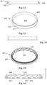
- FIGS 3-8 illustrate a container 101 for smokeless products for oral use according to a first aspect of the present invention.
- the container 101 comprises a base 103, a separating element 105, a retaining element 107 and a lid 109.
- the separating element 105 is located within the container 101.
- a first compartment 111 of the container 101, intended to contain unused products, is delimited by the base 103 and the separating element 105.
- a second compartment 113 of the container 101, intended to contain used products, is delimited by the lid 109 and the separating element 105.
- the separating element 105 may be used to separate used products from unused products.
- the base 103, the separating element 105, the retaining element 107 and the lid 109 are manufactured of the same polymeric material by means of injection moulding, which is a suitable way of manufacturing these elements and which also is beneficial for recycling purposes.
- the base 103 comprises a bottom wall 115 forming a bottom surface of the container 101 and a side wall 117 forming part of a side wall of the container 101.
- the lid 109 comprises a top wall 118, which has an external surface forming a top surface 119 of the container 101.
- the lid 109 also comprises a side wall 121 forming part of the side wall of the container 101.
- the lid 109 is releasable, such that it can be opened, and resealable, such that it can be closed again.
- the retaining element 107 extends along an upper portion of the side wall 117 of the base 103. Hence, the retaining element 107 forms a ring fitting on top of the base 103.
- the retaining element 107 has its own side wall 123.
- the retaining element 107 is releasably attached to the side wall 117 of the base 103 by means of a first snap-fit configuration 125, which is best seen in the detailed view of Fig. 7 .
- a first portion 127 of the side wall 123 of the retaining element 107 is located inside the side wall 117 of the base 103 and a second portion 129 of the side wall 123 of the retaining element 107 is located outside the side wall 117 of the base 103.
- the first snap-fit configuration 125 comprises a ring 131 formed at an external side of the side wall 117 of the base 103.
- the ring 131 is configured to cooperate with a corresponding ring 133 at an internal side of the second portion 129 of the side wall 123 of the retaining element 107.
- the ring 133 of the retaining element 107 is pressed down over the ring 131 of the base 103.
- the side wall 123 of the retaining element 107 and the side wall 117 of the base 103 have the same outer perimeter.
- An interspace 135 is provided between the retaining element 107 and the base 103 in order to make it easy for the user to remove the retaining element 107 from the base 103 to reach a product in the first compartment 111.
- the retaining element 107 is releasable, such that it can be opened, and resealable, such that it can be closed again.
- the lid 109 is releasably attached to an upper portion 137 of the side wall 123 of the retaining element 107 by means of a second snap-fit configuration 139.
- the second snap-fit configuration 139 comprises a ring 141 formed at an external side of the upper portion 137 of the side wall 123 of the retaining element 107.
- the ring 141 is configured to cooperate with a corresponding ring 143 at an internal side of the side wall 121 of the lid 109.
- An interspace 145 is provided between the lid 109 and the retaining element 107 in order to make it easy for the user to remove the lid 109 from the retaining element 107 in order to put a used product in the second compartment 113.
- the lid 109 is releasable, such that it can be opened, and resealable, such that it can be closed again.
- the side wall of the container 101 is smooth as seen in a height direction H of the container 101, except for the interspaces 135, 145 provided between the retaining element 107 and the base 103 and between the lid 109 and the retaining element 107 to make opening of the lid 109 and the retaining element 107, respectively, easier.
- the first snap-fit configuration 125 and the second snap-fit configuration 139 have the same geometry.
- the ring 131 of the base 103 and the ring 141 of the upper portion 137 of the side wall 123 of the retaining element 107 have the same geometry.
- the ring 133 of the internal side of the second portion 129 of the side wall 123 of the retaining element 107 and the ring 143 of the lid 109 have the same geometry, too.
- first snap-fit configuration 125 and the second snap-fit configuration 139 are illustrated as comprising two rings 131, 133; 141, 143 it would also be feasible to instead of at least one of the rings use a number of consecutive protuberances, e.g. ribs, extending in the peripheral direction.
- the separating element 105 is positionable in a first height position, see Figs. 5 and 7 , and a second height position, see Figs. 6 and 8 , relative to the top surface 119 with the first height position being closer to the top surface 119 than the second height position.
- the separating element 105 is movable from the first height position to the second height position by a linear translational displacement, i.e. downwards in the height direction H if comparing Figs. 5 and 6 .
- the displacement from the first height position to the second height position may be a strictly linear displacement.
- the separating element 105 has the same geometrical configuration in both height positions, i.e. it has not changed its geometrical shape due to e.g. deformation.
- the linear translational displacement of the separating element 105 is restricted to movement in a range between the first height position and the second height position.
- the user of the container 101 can move the separating element 105 between the first height position and the second height position but he/she cannot remove the separating element 105 from the retaining element 107 without breaking at least one of them.
- the risk of the separating element 105 undesirably falling out of the container 101 is reduced, or preferably avoided.
- the separating element 105 and the retaining element 107 together form an expandable disposal insert 147.
- the retaining element 107 comprises a first stop 149 facing inwards, the separating element 105 abutting the first stop 149 when in the first height position.
- the retaining element 107 further comprises a second stop 151 facing inwards, the separating element 105 abutting the second stop 151 when in the second height position.
- the first stop 149 defines the first height position
- the second stop 151 defines the second height position of the separating element 105.
- the second stop 151 comprises a plurality of protrusions extending in a circumferential direction along an inner perimeter of the retaining element 107.
- the protrusions are hook-shaped, with the hook shape being open upwards.
- the protuberances of the first stop 149 are sideways staggered in relation to the hook-shaped protrusions of the second stop 151, as may be gleaned in Fig. 3 , which makes injection moulding of the retaining element 107 easier.
- the separating element 105 comprises a bottom wall 153 and a side wall 155.
- the bottom wall 153 is rigid and planar. It is parallel to the bottom surface of the container 101 formed by the bottom wall 115 of the base 103.
- the bottom wall 153 of the separating element 105 is sufficiently rigid to retain its geometrical configuration, i.e. being undeformed, also when the second compartment is loaded by used products. According to the invention, the separating element 105 moves as an intact unit between the first and second height positions, instead of being deformed.
- the container system comprises
- the separating element 605 is inserted into the retaining element 607 from above.
Landscapes
- Engineering & Computer Science (AREA)
- Mechanical Engineering (AREA)
- Closures For Containers (AREA)
Priority Applications (2)
| Application Number | Priority Date | Filing Date | Title |
|---|---|---|---|
| EP23217461.5A EP4574701A1 (de) | 2023-12-18 | 2023-12-18 | Behälter mit trennelement |
| PCT/EP2024/086764 WO2025132337A1 (en) | 2023-12-18 | 2024-12-17 | Container comprising a separating element |
Applications Claiming Priority (1)
| Application Number | Priority Date | Filing Date | Title |
|---|---|---|---|
| EP23217461.5A EP4574701A1 (de) | 2023-12-18 | 2023-12-18 | Behälter mit trennelement |
Publications (1)
| Publication Number | Publication Date |
|---|---|
| EP4574701A1 true EP4574701A1 (de) | 2025-06-25 |
Family
ID=89223419
Family Applications (1)
| Application Number | Title | Priority Date | Filing Date |
|---|---|---|---|
| EP23217461.5A Pending EP4574701A1 (de) | 2023-12-18 | 2023-12-18 | Behälter mit trennelement |
Country Status (2)
| Country | Link |
|---|---|
| EP (1) | EP4574701A1 (de) |
| WO (1) | WO2025132337A1 (de) |
Citations (7)
| Publication number | Priority date | Publication date | Assignee | Title |
|---|---|---|---|---|
| KR20050081348A (ko) * | 2004-02-13 | 2005-08-19 | 삼성전자주식회사 | 용량가변 밀폐용기 |
| EP1667541A1 (de) | 2003-08-18 | 2006-06-14 | Gallaher Snus Ab | Deckel für tabakdose |
| WO2012069505A1 (en) | 2010-11-26 | 2012-05-31 | Swedish Match North Europe Ab | Arrangement for manufacturing of portion packets |
| US20150216230A1 (en) * | 2014-02-05 | 2015-08-06 | Imperial Tobacco Limited | Container For Snus, Tobacco Related or Smoking Related Articles and Method |
| WO2016202594A1 (en) * | 2015-06-16 | 2016-12-22 | Fiedler & Lundgren Ab | Container |
| WO2018086902A1 (en) | 2016-11-09 | 2018-05-17 | Swedish Match North Europe Ab | Method and device for positioning portion packets |
| WO2023104774A1 (en) | 2021-12-07 | 2023-06-15 | Swedish Match North Europe Ab | An oral smokeless product comprising an active agent and/or a flavour |
-
2023
- 2023-12-18 EP EP23217461.5A patent/EP4574701A1/de active Pending
-
2024
- 2024-12-17 WO PCT/EP2024/086764 patent/WO2025132337A1/en active Pending
Patent Citations (7)
| Publication number | Priority date | Publication date | Assignee | Title |
|---|---|---|---|---|
| EP1667541A1 (de) | 2003-08-18 | 2006-06-14 | Gallaher Snus Ab | Deckel für tabakdose |
| KR20050081348A (ko) * | 2004-02-13 | 2005-08-19 | 삼성전자주식회사 | 용량가변 밀폐용기 |
| WO2012069505A1 (en) | 2010-11-26 | 2012-05-31 | Swedish Match North Europe Ab | Arrangement for manufacturing of portion packets |
| US20150216230A1 (en) * | 2014-02-05 | 2015-08-06 | Imperial Tobacco Limited | Container For Snus, Tobacco Related or Smoking Related Articles and Method |
| WO2016202594A1 (en) * | 2015-06-16 | 2016-12-22 | Fiedler & Lundgren Ab | Container |
| WO2018086902A1 (en) | 2016-11-09 | 2018-05-17 | Swedish Match North Europe Ab | Method and device for positioning portion packets |
| WO2023104774A1 (en) | 2021-12-07 | 2023-06-15 | Swedish Match North Europe Ab | An oral smokeless product comprising an active agent and/or a flavour |
Also Published As
| Publication number | Publication date |
|---|---|
| WO2025132337A1 (en) | 2025-06-26 |
Similar Documents
| Publication | Publication Date | Title |
|---|---|---|
| US5115935A (en) | Disposable bag box for trash receptacle | |
| EP2349853B1 (de) | Behälter | |
| US11046487B2 (en) | Container with flexible separating wall | |
| EP0124305A1 (de) | Ineinanderstapelbarer Behälter für Farben | |
| WO2010005628A2 (en) | Tobacco container with insert | |
| WO2005016036A1 (en) | Snuff-box lid | |
| KR20100036236A (ko) | 가요성 배관을 분배하기 위한 카세트 | |
| CN116098370B (zh) | 用于粉末化妆品的可再装填盒 | |
| US4487331A (en) | Waste receptacle | |
| CA2203596A1 (en) | Container for filter tipped cigarette tubes used in hand made cigarettes | |
| EP4574701A1 (de) | Behälter mit trennelement | |
| EP2236433A1 (de) | Behälter | |
| US20020100758A1 (en) | Refuse container handle-liner dispenser unit | |
| EP0073195B1 (de) | Wegwerfbarer vorgefertiger Einsatz für ein Gefäss | |
| US20050167557A1 (en) | Retaining device | |
| JPH11165777A (ja) | 容 器 | |
| JPS6135011Y2 (de) | ||
| JP7446593B1 (ja) | 蓋体、容器セット及び包装体 | |
| EP4699463A1 (de) | Behälter zur lagerung mehrerer schnupfteile | |
| JPH0510766Y2 (de) | ||
| EP2429322B1 (de) | Behälter | |
| CN218594803U (zh) | 一种茶饼包装盒 | |
| EP4711301A1 (de) | Kindersichere flexible wand | |
| CN216762541U (zh) | 储物盒 | |
| CN211469103U (zh) | 一种带盖容器 |
Legal Events
| Date | Code | Title | Description |
|---|---|---|---|
| PUAI | Public reference made under article 153(3) epc to a published international application that has entered the european phase |
Free format text: ORIGINAL CODE: 0009012 |
|
| STAA | Information on the status of an ep patent application or granted ep patent |
Free format text: STATUS: THE APPLICATION HAS BEEN PUBLISHED |
|
| AK | Designated contracting states |
Kind code of ref document: A1 Designated state(s): AL AT BE BG CH CY CZ DE DK EE ES FI FR GB GR HR HU IE IS IT LI LT LU LV MC ME MK MT NL NO PL PT RO RS SE SI SK SM TR |
|
| STAA | Information on the status of an ep patent application or granted ep patent |
Free format text: STATUS: THE APPLICATION IS DEEMED TO BE WITHDRAWN |