EP4574642A1 - Mainmast of a sailing boat - Google Patents
Mainmast of a sailing boat Download PDFInfo
- Publication number
- EP4574642A1 EP4574642A1 EP24216076.0A EP24216076A EP4574642A1 EP 4574642 A1 EP4574642 A1 EP 4574642A1 EP 24216076 A EP24216076 A EP 24216076A EP 4574642 A1 EP4574642 A1 EP 4574642A1
- Authority
- EP
- European Patent Office
- Prior art keywords
- mainmast
- respect
- slats
- axis
- upright
- Prior art date
- Legal status (The legal status is an assumption and is not a legal conclusion. Google has not performed a legal analysis and makes no representation as to the accuracy of the status listed.)
- Pending
Links
Images

Classifications
-
- B—PERFORMING OPERATIONS; TRANSPORTING
- B63—SHIPS OR OTHER WATERBORNE VESSELS; RELATED EQUIPMENT
- B63B—SHIPS OR OTHER WATERBORNE VESSELS; EQUIPMENT FOR SHIPPING
- B63B15/00—Superstructures, deckhouses, wheelhouses or the like; Arrangements or adaptations of masts or spars, e.g. bowsprits
- B63B15/0083—Masts for sailing ships or boats
-
- B—PERFORMING OPERATIONS; TRANSPORTING
- B63—SHIPS OR OTHER WATERBORNE VESSELS; RELATED EQUIPMENT
- B63H—MARINE PROPULSION OR STEERING
- B63H9/00—Marine propulsion provided directly by wind power
- B63H9/04—Marine propulsion provided directly by wind power using sails or like wind-catching surfaces
-
- B—PERFORMING OPERATIONS; TRANSPORTING
- B63—SHIPS OR OTHER WATERBORNE VESSELS; RELATED EQUIPMENT
- B63H—MARINE PROPULSION OR STEERING
- B63H9/00—Marine propulsion provided directly by wind power
- B63H9/04—Marine propulsion provided directly by wind power using sails or like wind-catching surfaces
- B63H9/06—Types of sail; Constructional features of sails; Arrangements thereof on vessels
- B63H9/061—Rigid sails; Aerofoil sails
-
- B—PERFORMING OPERATIONS; TRANSPORTING
- B63—SHIPS OR OTHER WATERBORNE VESSELS; RELATED EQUIPMENT
- B63H—MARINE PROPULSION OR STEERING
- B63H9/00—Marine propulsion provided directly by wind power
- B63H9/04—Marine propulsion provided directly by wind power using sails or like wind-catching surfaces
- B63H9/08—Connections of sails to masts, spars, or the like
-
- B—PERFORMING OPERATIONS; TRANSPORTING
- B63—SHIPS OR OTHER WATERBORNE VESSELS; RELATED EQUIPMENT
- B63B—SHIPS OR OTHER WATERBORNE VESSELS; EQUIPMENT FOR SHIPPING
- B63B35/00—Vessels or similar floating structures specially adapted for specific purposes and not otherwise provided for
- B63B2035/009—Wind propelled vessels comprising arrangements, installations or devices specially adapted therefor, other than wind propulsion arrangements, installations, or devices, such as sails, running rigging, or the like, and other than sailboards or the like or related equipment
Definitions
- the present invention relates to a mainmast of a sailing boat, which is designed, in particular, for offshore sailing competitions, to which the following description will make explicit reference without thereby losing generality.
- the present invention finds advantageous but not exclusive application in a sailing boat having a single hull and provided with hydrodynamic lifting foils, usually indicated with the English term “hydrofoil”, or more simply “foil”, which are configured so as to have a hydrodynamic lift that is able to support the weight of the vessel and keep the hull out of the water when the vessel is sailing at relatively high speeds.
- a sailing boat essentially comprises a hull, closed at the top by a deck, at least one mainmast that protrudes vertically from the hull and from the deck, a forestay that connects the upper end portion of the mainmast to the bow of the hull, a main sail known as mainsail, hoisted on the mainmast, and a front sail known as jib, hoisted on the forestay.
- hydrodynamic lifting foils or hydrofoils or even more simply foils, are mounted on racing sailing boats, in order to keep the hull out of the water when given cruising speeds are reached, in a condition that is commonly referred to as "flying on the surface of the water", in order to reduce hydrodynamic resistance during navigation.
- hydrofoils have been used both on multi-hull sailing boats, especially on trimarans, and on mono-hull sailing boats, in order to maximize the speed of the boats designed for sports competitions.
- the mainmast has also been the subject of innovations, in particular by providing a cross-section having an elongated drop shape, in order to define a aerofoil.
- the mainmast is defined by a symmetrical, vertically extruded profile, which often also has the ability to rotate about its vertical axis with respect to the deck of the hull, in order to try to align the front edge, or leading edge, of the airfoil defined by the mainmast with respect to the direction of the apparent wind, namely, the AWA ("apparent wind angle").
- the presence of the jib in front of the mainmast generally has the effect of locally varying (in particular the effect of reducing) the angle of the air flowing towards the leading edge of the mainmast. Since the height of the jib is lower than the one of the mainmast, two different flow conditions are obtained along the leading edge of the mainmast: one at a lower area of the mainmast, influenced by the jib that is arranged in front, and also influenced by the resistance caused by the free surface of the sea on the wind, and the other, instead, at the upper area, where the incident air flows, in practice, are not altered by external conditions. In other words, the upper part of the mainmast (namely, the one that is essentially higher than the jib) is more exposed to a free air flow.
- the angle of incidence of the air flow towards the leading edge of the mainmast varies along the height of the mainmast.
- this variation in the direction of the incident air flow is further amplified by the effects of the boundary layer of the Earth.
- the object of the invention is therefore to satisfy the above-mentioned needs, preferably in a simple and/or effective and/or inexpensive manner.
- reference number 1 denotes, as a whole, a sailing boat, of the monohull type (illustrated partially and by simplifying some parts).
- the sailing boat 1 comprises a hull 11 extending along a longitudinal axis X between a forward end or bow, indicated by reference 12, and a rear end or stern, indicated by reference 13.
- the longitudinal axis X coincides with a normal advancement direction V of the sailing boat 1.
- the hull 11 extends, furthermore, in width and height along a transverse axis Y and along an axis Z, perpendicular to one another and to the longitudinal axis X, so as to form a Cartesian triplet of orthogonal axes, fixed with respect to the hull 11.
- the longitudinal axis X, the transverse axis Y and the axis Z are commonly referred to as the roll axis, the pitch axis, and the yaw axis, respectively.
- the hull 11 is delimited laterally by opposite sides 14, 15, extending between the bow 12 and the stern 13, and is normally closed at the top by a deck 16.
- the sailing boat 1 preferably comprises, furthermore, a keel or centreboard 18, which protrudes downwards along an axis parallel to the axis Z starting from a portion 19 of the hull 11 arranged in an intermediate position between the bow 12 and the stern 13, and centrally between the sides 14, 15 of the hull 11.
- the centreboard 18 has a lower end that supports or defines a bulb 20, having a mass (for example of about 8-10 tons) so as to place the centre of gravity of the sailing boat 1 in a relatively low position, in particular to allow the self-righting of the sailing boat 1 even in the event of a totally capsizing.
- the sailing boat 1 is of the type suitable for offshore sailing competitions and is provided with lateral arms, known and not illustrated, provided with respective hydrofoils or more simply foils (also known and not illustrated) and connected to the hull 11 so as to be independently movable between a lowered position, in which they immerse their foil in the water, and a raised position, in which they keep their foil out of the water.
- the sailing boat 1 comprises, furthermore, a mainmast 21 having a support base S mounted in a fixed position with respect to the hull 11 and an upright P, which protrudes upwards from the support base S along an axis which, in the specific example illustrated, coincides with the axis Z.
- the upright P of the mainmast 21 defines an airfoil or aerofoil.
- said profile is configured in order to have two opposite surfaces 21a and 21b, which are convex, extend from a leading edge 50 and are symmetrical with one another with respect to an ideal median plane M, on which the axis Z and the leading edge 50 lie.
- the surfaces 21a and 21b are arranged, one, upwind and, the other, downwind (in the example illustrated, the surface 21b is downwind).
- the leading edge 50 of the upright P is rectilinear and parallel to the axis Z, and the cross-sections of its airfoil have an invariant shape throughout its axial height.
- the dimensions of the cross-sections of the upright P remain equal to one another, throughout its height, without tapering.
- the sailing boat 1 comprises, furthermore, a mainsail 22, hoisted in a known manner and not described in detail on the mainmast 21.
- the mainsail 22 has opposite surfaces 22a, 22b ( Figure 5 ), arranged upwind and downwind, respectively. Taken together, the surfaces 21a, 21b, 22a, 22b define, as a whole, an airfoil exposed to the wind.
- the sailing boat 1 comprises, furthermore, one or more jibs, in the case illustrated two, indicated respectively with the references 25 and 26, which are arranged in front of the mainmast 21, namely, between the latter and the bow 12, and are configured, when sectioned with horizontal cross section planes, according to given aerofoils Q1, Q2 in each cross-section ( Figure 2 ).
- the jibs 25 and 26 define respective slats with respect to the airfoil defined by a lower portion P1 of the upright P, immediately adjacent towards the stern.
- the jibs 25, 26 are added to the aerofoil defined by the mainsail 22 and the mainmast 21, and increase the curvature of the profile overall exposed to the wind during navigation.
- an increase in lift is obtained from the sail system of the sailing boat 1, defined by the mainsail 22 and the jibs 25 and 26, which facilitates the motion of the boat in flight condition on the surface of the water, as well as obtaining high speeds.
- each jib 25, 26 has a shape and/or structure and/or dimensions such as to define an aerodynamic lift and/or aerodynamic resistance due to a relative speed with respect to the air during navigation.
- the jibs 25 and 26 have opposite surfaces 25a, 25b and 26a, 26b, arranged upwind and downwind, respectively.
- the jib 25 is arranged immediately adjacent to the lower portion P1 of the upright P of the mainmast 21 ( Figures 2 and 3 ). With respect to said lower portion P1, the jib 25 defines a slot 27 of given dimensions.
- the jib 26 (therefore the aerofoil Q2) is instead arranged in front of the jib 25, precisely between the latter and the bow 12.
- the jib 26 defines a slot 28 of given dimensions with the jib 25 ( Figures 1 and 2 ) .
- the jib 25 comprises:
- the aerofoils Q1 of the ribs 31 have dimensions that gradually taper upwards, to be fitted by a triangular sail 33; according to a possible alternative not illustrated, the aerofoils Q1 of the ribs 31 could also have constant dimensions.
- the jib 26 also preferably comprises:
- the support elements 29, 30 are defined by forestays that connect a portion of the upper end 21c of the mainmast 21 to a portion of the bow of the hull 11.
- the main directions A, B having prevalent extension of the support elements 29, 30 are therefore oblique with respect to the vertical axis Z and transverse with respect to the plane identified by the longitudinal axis X and transversal axis Y.
- the sailing boat 1 comprises, furthermore, one or more actuators (not illustrated) to move the ribs 31, 32 and/or the support elements 29, 30 along planes transverse to the longitudinal axis X and to the vertical axis Z.
- actuators not illustrated
- a first actuator is used to move the support element 29 and a second actuator, different from the first, to move the support element 30.
- the support elements 29, 30 engage respective through grooves 39, 40 obtained in the deck 16 and shaped like cams to define the movement trajectories of the support elements 29, 30.
- the lower portion P1 of the upright P is mounted on the support base S so as to be rotatable about the axis Z.
- the upright P can be oriented with respect to the support base S (and therefore with respect to the surrounding space) about the axis Z using known techniques, for example by operating an actuator 51 (schematically illustrated) carried by the support base S and/or arranged below deck in Figure 3 ).
- an actuator 51 (schematically illustrated) carried by the support base S and/or arranged below deck in Figure 3 ).
- this adjustment of orientation about the axis Z is performed as a function of the configuration of the jib 25, which determines the angle of incidence of the air flowing in the slot 27 towards the leading edge 50 at the lower portion P1 of the upright P.
- the jib 25 has a height that is less than the one of the mainmast 21, so it influences the angle of incidence of the air flow only for the lower portion P1, but not for the remaining part of the upright P, defined by an upper portion indicated with the reference P2 in Figures from 3 to 6.
- the upper portion P2 in fact, is impacted by a free air flow, which is substantially not influenced by the presence of the jibs 25 and 26.
- the jib 26 extends higher than the jib 25, but the upper end of the jib 26 is relatively distant from the upright P, so it does not tend to influence the direction of the air flow towards the upper portion P2.
- the air flow that impacts the upper portion P2 of the upright P tends not to be influenced even by aerodynamic resistance and/or boundary layer effects caused by the surface of the Earth, namely, by the free surface of the sea on which the sailing boat 1 is travelling.
- the mainmast 21 comprises two slats 52a and 52b, defined by respective rigid elements that are elongated in directions parallel to the axis Z, are arranged exclusively at the upper portion P2 of the upright P, and are fixed to the upper portion P2 in positions spaced apart from the surfaces 21a and 21b, so as to define respective slots 53a and 53b ( Figure 6 ) with respect to said surfaces 21a and 21b.
- the lower portion P1 does not support any slats.
- the slats 52a and 52b are symmetrical to one another with respect to the plane M, so as to make the behaviour of the airfoil of the upper portion P2 of the upright P equal in the case of starboard tacks and port tacks.
- each of the slats 52a and 52b is fixed in a cantilever manner to the upper portion P2 of the upright P, by at least two legs, provided for example at the lower end and at the upper end of the same slat 52a,52b.
- the slats 52a, 52b could be defined by substantially rigid elements, for example by plates, which are movable between a close position and a spaced position with respect to the upper portion P2 of the upright P, preferably independently of one another, under the action of an actuator mechanism arranged inside the upright P, namely, with an activation and deactivation movement similar to the one which occurs for the slats usually provided for lifting wings in the aeronautic field.
- the rigid, or substantially rigid, elements defining the slats 52a and 52b have a cross-section with position, shape and dimensions that are invariant at the different heights of the upper portion P2 of the upright P.
- the cross-sections of the slats 52a, 52b could also be designed with variations along the axis Z with regard to position and/or shape and/or dimensions.
- the slat 52b is arranged downwind and performs a guiding function that channels the air flow into the respective slot 53b, thus counteracting the tendency for the air flow to detach from the respective surface 21b and therefore counteracting the stalling of the airfoil at the upper portion P2 of the upright P.
- the slat 52b allows to increase the angle of incidence of the air flow with respect to the leading edge 50, at the upper portion P2 where it is mounted, without incurring stalling phenomena of the airfoil.
- the slat 52a is the one arranged downwind.
- slats 52a and 52b allow the operating range of the airfoil of the upper portion P2 of the upright P to be extended, in relation to the angle of incidence of the air flow directed towards the leading edge 50. In other words, the stall conditions are moved away towards greater angles of incidence compared to the case in which slats 52a and 52b were absent.
- the extension of the operating range with respect to the angles of incidence of the air flows at the upper portion P2 allows to better deal with gusts of wind with variations in direction, as well as the small and continuous adjustments of course normally associated with the rudder command during a sailing competition.
- the preferred solution presented is also extremely simple, and easy to install.
- slats 52a, 52b on the upper portion P2 of the mainmast 21 is independent of the type and number of jibs that are provided in front of the mainmast 21 (for example, the jib sails could be of the traditional type, without ribs).
- slats 52a and 52b could be useful even without the use of any jib in front of the mainmast 21, in order to compensate for differences in the angle of incidence of the apparent wind on the leading edge 50 of the upright P, depending on the height of the latter, due to the boundary layer effects caused by the sea surface, which tends to change the wind conditions compared to those at the upper end of the mainmast 21.
- the external profile of the slats 52a, 52b could be different from the one illustrated in the attached figures as an example.
- the position of the slats 52a and 52b with respect to the surfaces 21a and 21b could vary as the height along the upper portion P2 varies, so they may not be perfectly parallel to the axis Z.
- the axis of the upright P may not coincide with the yaw axis of the boat 1 and/or may not be straight: for example, the upper portion P2 could be canted towards the stern.
Landscapes
- Engineering & Computer Science (AREA)
- Chemical & Material Sciences (AREA)
- Combustion & Propulsion (AREA)
- Mechanical Engineering (AREA)
- Ocean & Marine Engineering (AREA)
- Life Sciences & Earth Sciences (AREA)
- Sustainable Development (AREA)
- Sustainable Energy (AREA)
- Toys (AREA)
- Jib Cranes (AREA)
- Structures Of Non-Positive Displacement Pumps (AREA)
Abstract
Description
- This patent application claims priority from
Italian patent application no. 102023000027792 filed on December 22, 2023 - The present invention relates to a mainmast of a sailing boat, which is designed, in particular, for offshore sailing competitions, to which the following description will make explicit reference without thereby losing generality.
- In particular, the present invention finds advantageous but not exclusive application in a sailing boat having a single hull and provided with hydrodynamic lifting foils, usually indicated with the English term "hydrofoil", or more simply "foil", which are configured so as to have a hydrodynamic lift that is able to support the weight of the vessel and keep the hull out of the water when the vessel is sailing at relatively high speeds.
- As is known, a sailing boat essentially comprises a hull, closed at the top by a deck, at least one mainmast that protrudes vertically from the hull and from the deck, a forestay that connects the upper end portion of the mainmast to the bow of the hull, a main sail known as mainsail, hoisted on the mainmast, and a front sail known as jib, hoisted on the forestay.
- In regular sailing conditions, the mainsail is used to sail upwind, whereas the jib helps the boat tack correctly and allows to maintain control of the bow.
- It is also known that hydrodynamic lifting foils, or hydrofoils or even more simply foils, are mounted on racing sailing boats, in order to keep the hull out of the water when given cruising speeds are reached, in a condition that is commonly referred to as "flying on the surface of the water", in order to reduce hydrodynamic resistance during navigation.
- In recent decades, hydrofoils have been used both on multi-hull sailing boats, especially on trimarans, and on mono-hull sailing boats, in order to maximize the speed of the boats designed for sports competitions.
- In order to try to obtain high speeds, especially for this type of racing boat, there is a strong need to increase the component of the wind force in the advancement direction of the boat and, consequently, minimize the lateral component and/or any losses.
- In this regard, in the last decade, some solutions known from the world of racing cars (for example from the world of Formula 1), as well as from the aeronautical field, have been proposed and successfully applied to racing sailing boats. For example, sails have begun to be designed as real airfoils capable of maximizing the wind thrust in the advancement direction for each apparent wind angle.
- Furthermore, the mainmast has also been the subject of innovations, in particular by providing a cross-section having an elongated drop shape, in order to define a aerofoil. In other words, the mainmast is defined by a symmetrical, vertically extruded profile, which often also has the ability to rotate about its vertical axis with respect to the deck of the hull, in order to try to align the front edge, or leading edge, of the airfoil defined by the mainmast with respect to the direction of the apparent wind, namely, the AWA ("apparent wind angle").
- The presence of the jib in front of the mainmast generally has the effect of locally varying (in particular the effect of reducing) the angle of the air flowing towards the leading edge of the mainmast. Since the height of the jib is lower than the one of the mainmast, two different flow conditions are obtained along the leading edge of the mainmast: one at a lower area of the mainmast, influenced by the jib that is arranged in front, and also influenced by the resistance caused by the free surface of the sea on the wind, and the other, instead, at the upper area, where the incident air flows, in practice, are not altered by external conditions. In other words, the upper part of the mainmast (namely, the one that is essentially higher than the jib) is more exposed to a free air flow.
- Therefore, in summary, the angle of incidence of the air flow towards the leading edge of the mainmast varies along the height of the mainmast. As mentioned above, this variation in the direction of the incident air flow is further amplified by the effects of the boundary layer of the Earth.
- Given this variation of the flow angle with height, in known solutions it is necessary to adopt a compromise in the adjustment of the mainmast angle about its vertical axis, in order to maximize the thrust force and, at the same time, avoid a possible stall of the airfoil of the mainmast along the upper area (due to the misalignment of its leading edge with respect to the free air flow). In particular, this stall condition occurs especially in the presence of gusts of wind having variable angles of incidence.
- The search for an optimal compromise is also demonstrated by an extensive torsion in the highest parts of the mainsail, which are released by loosening the mainsail sticks.
- In light of these considerations, there is a need to improve the aerodynamic performance of the mainmast, in order to broaden the operating range with respect to the angle of incidence of the apparent wind and therefore eliminate or reduce the risks of stalling of its airfoil, even in the presence of gusts of wind with variable directions, especially in order to be highly performing during a sailing competition.
- The object of the invention is therefore to satisfy the above-mentioned needs, preferably in a simple and/or effective and/or inexpensive manner.
- The above-mentioned object is achieved by a mainmast of a sailing boat, as defined in
claim 1. - The dependent claims define particular embodiments of the invention.
- Hereinafter, for a better understanding of the present invention, a preferred embodiment will be described by way of a non-limiting example, with reference to the attached drawings, wherein:
-
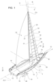
Figure 1 is a simplified perspective view, with schematic parts, relating to a sailing boat provided with a mainmast according to the preferred embodiment of the present invention; -
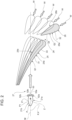
Figure 2 is a schematic cross section, on an enlarged scale and with parts removed for clarity, along the horizontal plane identified by the trace II-II ofFigure 1 , in which different positions obtainable for two jibs arranged at the bow of the sailing boat are shown; -
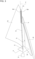
Figure 3 is a different perspective view, simplified and on an enlarged scale, showing a detail of the mainmast shown inFigure 1 ; -
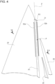
Figure 4 shows the detail ofFigure 3 , on a further enlarged scale; -
Figure 5 is a schematic cross section, obtained through the horizontal plane identified by the trace V-V inFigure 4 ; and -
Figure 6 is relative to a detail ofFigure 5 , and shows, in a simplified way, air flow lines incident on the mainmast. - In
Figure 1 ,reference number 1 denotes, as a whole, a sailing boat, of the monohull type (illustrated partially and by simplifying some parts). - The
sailing boat 1 comprises ahull 11 extending along a longitudinal axis X between a forward end or bow, indicated byreference 12, and a rear end or stern, indicated byreference 13. The longitudinal axis X coincides with a normal advancement direction V of thesailing boat 1. - The
hull 11 extends, furthermore, in width and height along a transverse axis Y and along an axis Z, perpendicular to one another and to the longitudinal axis X, so as to form a Cartesian triplet of orthogonal axes, fixed with respect to thehull 11. The longitudinal axis X, the transverse axis Y and the axis Z are commonly referred to as the roll axis, the pitch axis, and the yaw axis, respectively. - The
hull 11 is delimited laterally byopposite sides bow 12 and thestern 13, and is normally closed at the top by adeck 16. - The
sailing boat 1 preferably comprises, furthermore, a keel orcentreboard 18, which protrudes downwards along an axis parallel to the axis Z starting from aportion 19 of thehull 11 arranged in an intermediate position between thebow 12 and thestern 13, and centrally between thesides hull 11. Preferably, thecentreboard 18 has a lower end that supports or defines abulb 20, having a mass (for example of about 8-10 tons) so as to place the centre of gravity of thesailing boat 1 in a relatively low position, in particular to allow the self-righting of thesailing boat 1 even in the event of a totally capsizing. - Preferably, the
sailing boat 1 is of the type suitable for offshore sailing competitions and is provided with lateral arms, known and not illustrated, provided with respective hydrofoils or more simply foils (also known and not illustrated) and connected to thehull 11 so as to be independently movable between a lowered position, in which they immerse their foil in the water, and a raised position, in which they keep their foil out of the water. - The
sailing boat 1 comprises, furthermore, a mainmast 21 having a support base S mounted in a fixed position with respect to thehull 11 and an upright P, which protrudes upwards from the support base S along an axis which, in the specific example illustrated, coincides with the axis Z. According to an aspect of the present invention, the upright P of themainmast 21 defines an airfoil or aerofoil. As shown in a simplified manner inFigure 2 , said profile is configured in order to have twoopposite surfaces edge 50 and are symmetrical with one another with respect to an ideal median plane M, on which the axis Z and the leadingedge 50 lie. In use, thesurfaces surface 21b is downwind). - Given the symmetry with respect to the plane M, the leading
edge 50 of the upright P is rectilinear and parallel to the axis Z, and the cross-sections of its airfoil have an invariant shape throughout its axial height. Preferably, the dimensions of the cross-sections of the upright P remain equal to one another, throughout its height, without tapering. - The
sailing boat 1 comprises, furthermore, amainsail 22, hoisted in a known manner and not described in detail on the mainmast 21. Themainsail 22 hasopposite surfaces Figure 5 ), arranged upwind and downwind, respectively. Taken together, thesurfaces - Advantageously, the
sailing boat 1 comprises, furthermore, one or more jibs, in the case illustrated two, indicated respectively with thereferences mainmast 21, namely, between the latter and thebow 12, and are configured, when sectioned with horizontal cross section planes, according to given aerofoils Q1, Q2 in each cross-section (Figure 2 ). - Preferably, but not exclusively, the
jibs - In practice, the
jibs mainsail 22 and themainmast 21, and increase the curvature of the profile overall exposed to the wind during navigation. Compared to known solutions, for the same heeling torque, an increase in lift is obtained from the sail system of thesailing boat 1, defined by themainsail 22 and thejibs - In more general terms, each
jib - As schematized in
Figure 2 , thejibs opposite surfaces - As mentioned above, the
jib 25 is arranged immediately adjacent to the lower portion P1 of the upright P of the mainmast 21 (Figures 2 and3 ). With respect to said lower portion P1, thejib 25 defines aslot 27 of given dimensions. - The jib 26 (therefore the aerofoil Q2) is instead arranged in front of the
jib 25, precisely between the latter and thebow 12. - The
jib 26 defines aslot 28 of given dimensions with the jib 25 (Figures 1 and2 ) . - Preferably, with reference to
Figure 1 , thejib 25 comprises: - a
support element 29 with an elongated geometry along a respective main direction A having a prevalent extension with respect to the other dimensions, arranged in front of the mainmast 21 and protruding upwards with respect to thehull 11 along the aforementioned main direction A; - a plurality of
ribs 31, each defining a respective aerofoil Q1 and carried transversally in a cantilevered manner by thesupport element 29 in parallel positions and spaced apart from one another along the main direction A of extension of thesupport element 29; and - a
sail 33 fitted on theribs 31 in the manner of a bag open at its opposite ends so as to form a respective closed loop around theribs 31. - In the illustrated case, the aerofoils Q1 of the
ribs 31 have dimensions that gradually taper upwards, to be fitted by atriangular sail 33; according to a possible alternative not illustrated, the aerofoils Q1 of theribs 31 could also have constant dimensions. - Similarly to what has been shown for the
jib 25, thejib 26 also preferably comprises: - a
support element 30 with an elongated geometry along a respective main direction B having a prevalent extension with respect to the other dimensions, arranged in front of the mainmast 21 and thesupport element 29 and protruding upwards with respect to thehull 11 along the aforementioned main direction B; - a plurality of
ribs 32, each defining a respective aerofoil Q2 and carried transversally in a cantilevered manner by thesupport element 30 in parallel positions and spaced apart from one another along the main extension direction B of thesupport element 30; and - a
sail 34 fitted on theribs 32 in the shape of a bag open at its opposite ends forming a respective closed loop around theribs 32. - In the illustrated case, the
support elements upper end 21c of the mainmast 21 to a portion of the bow of thehull 11. - The main directions A, B having prevalent extension of the
support elements - Preferably, the
sailing boat 1 comprises, furthermore, one or more actuators (not illustrated) to move theribs support elements - In the illustrated case, a first actuator is used to move the
support element 29 and a second actuator, different from the first, to move thesupport element 30. - Preferably, the
support elements grooves deck 16 and shaped like cams to define the movement trajectories of thesupport elements - The positions obtainable by the
support elements ribs respective jibs grooves Figure 2 . Said positions can be varied according to the direction of the apparent wind during navigation. In particular, in the case of tacking or jibing, the profiles Q1, Q2 can be oriented towards the wind on the opposite tacks. - The effect of this preferred configuration of the
jibs sailing boat 1. In practice, the curvature of the airfoil defined by the assembly of sails is advanced in front of the mainmast 21, at thejibs mainsail 22. - According to an aspect of the present invention, as schematized in
Figure 3 , the lower portion P1 of the upright P is mounted on the support base S so as to be rotatable about the axis Z. In other words, the upright P can be oriented with respect to the support base S (and therefore with respect to the surrounding space) about the axis Z using known techniques, for example by operating an actuator 51 (schematically illustrated) carried by the support base S and/or arranged below deck inFigure 3 ). In this way, it is possible to adjust the position of the leadingedge 50 of the airfoil of the upright P as a function of the angle of incidence of the air flowing towards the upright P, in order to optimize the aerodynamic conditions of the air flow along thesurfaces jib 25, which determines the angle of incidence of the air flowing in theslot 27 towards the leadingedge 50 at the lower portion P1 of the upright P. - In particular, the
jib 25 has a height that is less than the one of the mainmast 21, so it influences the angle of incidence of the air flow only for the lower portion P1, but not for the remaining part of the upright P, defined by an upper portion indicated with the reference P2 in Figures from 3 to 6. The upper portion P2, in fact, is impacted by a free air flow, which is substantially not influenced by the presence of thejibs Figure 4 and the cross section inFigure 5 , it can be noted that thejib 26 extends higher than thejib 25, but the upper end of thejib 26 is relatively distant from the upright P, so it does not tend to influence the direction of the air flow towards the upper portion P2. - Given the considerable height of the mainmast 21 (typically around 15 meters, for example), the air flow that impacts the upper portion P2 of the upright P tends not to be influenced even by aerodynamic resistance and/or boundary layer effects caused by the surface of the Earth, namely, by the free surface of the sea on which the
sailing boat 1 is travelling. - Consequently, as mentioned above, the conditions of the air flows directed towards the airfoil of the upright P are different depending on the height position along the upright P. To overcome the different directions of incidence of said air flows, according to the present invention the
mainmast 21 comprises twoslats surfaces respective slots Figure 6 ) with respect to saidsurfaces - The
slats - For example, each of the
slats same slat - According to not illustrated alternatives, the
slats - Preferably, the rigid, or substantially rigid, elements defining the
slats slats - As illustrated in a simplified way in the example of
Figure 6 , theslat 52b is arranged downwind and performs a guiding function that channels the air flow into therespective slot 53b, thus counteracting the tendency for the air flow to detach from therespective surface 21b and therefore counteracting the stalling of the airfoil at the upper portion P2 of the upright P. - In other words, the
slat 52b allows to increase the angle of incidence of the air flow with respect to the leadingedge 50, at the upper portion P2 where it is mounted, without incurring stalling phenomena of the airfoil. The same situation obviously occurs when theslat 52a is the one arranged downwind. - It is therefore evident that
slats edge 50. In other words, the stall conditions are moved away towards greater angles of incidence compared to the case in which slats 52a and 52b were absent. - Thanks to this extension of the operating range of the airfoil of the upper portion P2, it is possible to set the orientation of the upright P about the axis Z so that the airfoil of its lower portion P1 is optimized for the flow conditions caused by the
jib 25, without losing aerodynamic efficiency at the upper portion P2. - At the same time, the extension of the operating range with respect to the angles of incidence of the air flows at the upper portion P2 allows to better deal with gusts of wind with variations in direction, as well as the small and continuous adjustments of course normally associated with the rudder command during a sailing competition.
- The preferred solution presented is also extremely simple, and easy to install.
- Finally, it is clear that modifications and variations can be made to the
mainmast 21 and to thesailing boat 1 described and illustrated herein with reference to the attached figures without going beyond the scope of protection defined by the following claims. - In particular, the presence of
slats - Furthermore,
slats edge 50 of the upright P, depending on the height of the latter, due to the boundary layer effects caused by the sea surface, which tends to change the wind conditions compared to those at the upper end of themainmast 21. - Furthermore, the external profile of the
slats - Furthermore, as mentioned above, while maintaining mutual symmetry with respect to the plane M, the position of the
slats surfaces slats - Finally, the axis of the upright P may not coincide with the yaw axis of the
boat 1 and/or may not be straight: for example, the upper portion P2 could be canted towards the stern.
Claims (8)
- A mainmast (21) for a sailing boat (1), the mainmast comprising:a) a support base (S) suitable to be fixed with respect to a hull (11) of said sailing boat (1);b) an upright (P), which extends along an axis from said support base (S), comprises a lower portion (P1), adjacent to said support base (S), and an upper portion (P2), opposite to said lower portion (P1) along said axis, and defines an airfoil having a leading edge (50) and two convex surfaces (21a,21b);wherein said convex surfaces (21a,21b) extend from said leading edge (50) symmetrically to each other with respect to an ideal median plane (M), on which said leading edge (50) and said axis lie;wherein said lower portion (P1) is rotatable about said axis with respect to said support base (S) to orient said upright (P) and, therefore, said leading edge (50);wherein the mainmast further comprises two slats (52a,52b) symmetrical to each other with respect to said ideal median plane (M);characterized in that said slats (52a,52b) are arranged exclusively at said upper portion (P2) and so as to be spaced respectively from said convex surfaces (21a,21b) and, therefore, define respective slots (53a,53b).
- The mainmast according to claim 1, wherein said slats (52a,52b) are fixed with respect to said upper portion (P2).
- The mainmast according to claim 1 or 2, wherein said slats (52a,52b) are defined by respective substantially rigid bodies.
- The mainmast according to any one of the preceding claims, wherein said slats (52a,52b) are parallel to said axis.
- The mainmast according to any one of the preceding claims, wherein said slats (52a,52b) have a cross-section having an invariant position with respect to said convex surfaces (21a,21b) as the height varies along said upper portion (P2).
- The mainmast according to any one of the preceding claims, wherein said slats (52a,52b) have a cross-section having an invariant shape as the height varies along said upper portion (P2) .
- The mainmast according to any one of the preceding claims, wherein said slats (52a,52b) have a cross-section having invariant dimensions as the height varies along said upper portion (P2).
- The mainmast according to any one of the preceding claims, wherein a mainsail (22) is hoisted on the mainmast.
Applications Claiming Priority (1)
| Application Number | Priority Date | Filing Date | Title |
|---|---|---|---|
| IT102023000027792A IT202300027792A1 (en) | 2023-12-22 | 2023-12-22 | MAST OF A SAILING BOAT |
Publications (1)
| Publication Number | Publication Date |
|---|---|
| EP4574642A1 true EP4574642A1 (en) | 2025-06-25 |
Family
ID=90057381
Family Applications (1)
| Application Number | Title | Priority Date | Filing Date |
|---|---|---|---|
| EP24216076.0A Pending EP4574642A1 (en) | 2023-12-22 | 2024-11-28 | Mainmast of a sailing boat |
Country Status (3)
| Country | Link |
|---|---|
| EP (1) | EP4574642A1 (en) |
| IT (1) | IT202300027792A1 (en) |
| WO (1) | WO2025133775A1 (en) |
Citations (3)
| Publication number | Priority date | Publication date | Assignee | Title |
|---|---|---|---|---|
| SU1178649A1 (en) * | 1982-04-27 | 1985-09-15 | Предприятие П/Я А-1459 | Sailing ship truss mast |
| WO1986004035A1 (en) * | 1985-01-07 | 1986-07-17 | The University Of Southampton | Aerofoils for floating vessels |
| GB2599118A (en) * | 2020-09-24 | 2022-03-30 | Ba Tech Limited | Propulsion device |
-
2023
- 2023-12-22 IT IT102023000027792A patent/IT202300027792A1/en unknown
-
2024
- 2024-11-28 WO PCT/IB2024/061985 patent/WO2025133775A1/en active Pending
- 2024-11-28 EP EP24216076.0A patent/EP4574642A1/en active Pending
Patent Citations (3)
| Publication number | Priority date | Publication date | Assignee | Title |
|---|---|---|---|---|
| SU1178649A1 (en) * | 1982-04-27 | 1985-09-15 | Предприятие П/Я А-1459 | Sailing ship truss mast |
| WO1986004035A1 (en) * | 1985-01-07 | 1986-07-17 | The University Of Southampton | Aerofoils for floating vessels |
| GB2599118A (en) * | 2020-09-24 | 2022-03-30 | Ba Tech Limited | Propulsion device |
Also Published As
| Publication number | Publication date |
|---|---|
| WO2025133775A1 (en) | 2025-06-26 |
| WO2025133775A8 (en) | 2025-11-13 |
| IT202300027792A1 (en) | 2025-06-22 |
Similar Documents
| Publication | Publication Date | Title |
|---|---|---|
| KR102768978B1 (en) | Propulsion device | |
| US6918346B2 (en) | Marine craft towed by a kite-type canopy | |
| US5163377A (en) | Sailing yacht | |
| US20110168071A1 (en) | System and method of adjusting the location and position of the foresail on a sailboat | |
| EP1248724B1 (en) | Wind-powered air/water interface craft having various wing angles and configurations | |
| EP3052379B1 (en) | Method for rigging and controlling a wing sail | |
| US20130014683A1 (en) | Adjusting rigid foil spar system | |
| US6691632B2 (en) | Sailing craft stable when airborne | |
| US20080245284A1 (en) | Three Degree-of-Freedom Pivot Assembly, Sail-Mounted Ballast, and Sail Control System for High Speed Sailboats | |
| US4453483A (en) | Sail assembly for vessels | |
| US6732670B2 (en) | Sailing craft | |
| US3561388A (en) | Hydrofoil saling craft | |
| EP4574642A1 (en) | Mainmast of a sailing boat | |
| US4945845A (en) | High-speed sailing craft | |
| US5088431A (en) | Sailing vessels | |
| EP4574643A1 (en) | Main mast of a sailing boat | |
| EP4524022A1 (en) | Boat with improved sail system | |
| US20070137541A1 (en) | Twister wings sailboat | |
| US6662738B2 (en) | Lifting-sail boat apparatus and method | |
| EP2752360A2 (en) | Improved sailing vessel | |
| US10377447B2 (en) | Sailboat | |
| WO2022064195A1 (en) | A wing sail for a wing propelled craft | |
| WO2025244551A1 (en) | Sail system and sail system operating method | |
| US5918561A (en) | Lift creating sail and sail system | |
| EP1557350A1 (en) | High-performance sailing boat using wing sections and lifting sails |
Legal Events
| Date | Code | Title | Description |
|---|---|---|---|
| PUAI | Public reference made under article 153(3) epc to a published international application that has entered the european phase |
Free format text: ORIGINAL CODE: 0009012 |
|
| STAA | Information on the status of an ep patent application or granted ep patent |
Free format text: STATUS: THE APPLICATION HAS BEEN PUBLISHED |
|
| AK | Designated contracting states |
Kind code of ref document: A1 Designated state(s): AL AT BE BG CH CY CZ DE DK EE ES FI FR GB GR HR HU IE IS IT LI LT LU LV MC ME MK MT NL NO PL PT RO RS SE SI SK SM TR |
|
| STAA | Information on the status of an ep patent application or granted ep patent |
Free format text: STATUS: REQUEST FOR EXAMINATION WAS MADE |
|
| STAA | Information on the status of an ep patent application or granted ep patent |
Free format text: STATUS: EXAMINATION IS IN PROGRESS |
|
| 17P | Request for examination filed |
Effective date: 20251230 |
|
| 17Q | First examination report despatched |
Effective date: 20260120 |