EP4574640A1 - A marine drive unit - Google Patents
A marine drive unit Download PDFInfo
- Publication number
- EP4574640A1 EP4574640A1 EP23219990.1A EP23219990A EP4574640A1 EP 4574640 A1 EP4574640 A1 EP 4574640A1 EP 23219990 A EP23219990 A EP 23219990A EP 4574640 A1 EP4574640 A1 EP 4574640A1
- Authority
- EP
- European Patent Office
- Prior art keywords
- cable
- drive system
- cutter
- electrical drive
- electrical
- Prior art date
- Legal status (The legal status is an assumption and is not a legal conclusion. Google has not performed a legal analysis and makes no representation as to the accuracy of the status listed.)
- Withdrawn
Links
Images


Classifications
-
- B—PERFORMING OPERATIONS; TRANSPORTING
- B63—SHIPS OR OTHER WATERBORNE VESSELS; RELATED EQUIPMENT
- B63B—SHIPS OR OTHER WATERBORNE VESSELS; EQUIPMENT FOR SHIPPING
- B63B43/00—Improving safety of vessels, e.g. damage control, not otherwise provided for
- B63B43/18—Improving safety of vessels, e.g. damage control, not otherwise provided for preventing collision or grounding; reducing collision damage
-
- B—PERFORMING OPERATIONS; TRANSPORTING
- B63—SHIPS OR OTHER WATERBORNE VESSELS; RELATED EQUIPMENT
- B63H—MARINE PROPULSION OR STEERING
- B63H21/00—Use of propulsion power plant or units on vessels
- B63H21/12—Use of propulsion power plant or units on vessels the vessels being motor-driven
- B63H21/17—Use of propulsion power plant or units on vessels the vessels being motor-driven by electric motor
-
- B—PERFORMING OPERATIONS; TRANSPORTING
- B63—SHIPS OR OTHER WATERBORNE VESSELS; RELATED EQUIPMENT
- B63B—SHIPS OR OTHER WATERBORNE VESSELS; EQUIPMENT FOR SHIPPING
- B63B43/00—Improving safety of vessels, e.g. damage control, not otherwise provided for
- B63B43/18—Improving safety of vessels, e.g. damage control, not otherwise provided for preventing collision or grounding; reducing collision damage
- B63B43/20—Feelers
-
- B—PERFORMING OPERATIONS; TRANSPORTING
- B63—SHIPS OR OTHER WATERBORNE VESSELS; RELATED EQUIPMENT
- B63B—SHIPS OR OTHER WATERBORNE VESSELS; EQUIPMENT FOR SHIPPING
- B63B2241/00—Design characteristics
- B63B2241/20—Designs or arrangements for particular purposes not otherwise provided for in this class
Definitions
- the disclosure relates generally to a drive unit.
- the disclosure relates to a marine drive unit for a marine vessel.
- the disclosure can be applied to marine vessels, such as water crafts, motorboats, work boats, sport vessels, boats, ships, among other vessel types.
- marine vessels such as water crafts, motorboats, work boats, sport vessels, boats, ships, among other vessel types.
- the disclosure may be described with respect to a particular marine vessel, the disclosure is not restricted to any particular marine vessel.
- an electrical drive system for a marine vessel comprises an electric machine arranged below a water level, an inboard electrical energy storage system wherein the electric machine is connected to the inboard electrical energy storage system via at least one electric cable, and at least one cable cutter arranged to cut the at least one electric cable in the event of impact.
- the first aspect of the disclosure may seek to provide a safe system in the event of a high external force acting on the system, such as for example an impact from a rock or log.
- a technical benefit may include providing a safe way of separating the electrical wires from the different parts. It is beneficial to be able to separate the electric machine from the rest of the system in the event of a severe impact, as it prevents the electric machine from hanging after and pulling/jerking in the electrical cables. A controlled behavior of the electrical cables are thus beneficial.
- the electrical drive system is further comprising an elongate housing which encapsulates at least an electric motor of the electric machine.
- a technical benefit may include proving a housing that protects the electric motor of external conditions such as water and external forces.
- the elongate housing further provides a pod solution, which has many known benefits.
- the elongate housing has a distal end portion.
- the distal end portion may be cone-shaped.
- a technical benefit may include providing a streamlined body that is hydrodynamic.
- the electrical drive system further comprises a mechanical switch.
- the cable cutter may be activated by said mechanical switch upon impact.
- a technical benefit may include providing a mechanical activation that works even if the electricity of the system has been deactivated.
- the switch is arranged in said distal end portion.
- a technical benefit may include an early onset of the switch as the distal end portions is exposed to an external pressure.
- the cable cutter is activated once the fixture is deformed due to said impact.
- a technical benefit may include an early onset of the activation of the cable cutter.
- a technical benefit may include decreasing the risk of incorrect activation.
- the cable cutter is mechanically driven.
- a technical benefit may include that the cable cutter is operational even if the electricity of the system has been deactivated.
- the cable cutter comprises a guillotine cutter.
- a technical benefit may include being cost-effective while at the same time being efficient and reliable.
- the cable cutter is configured to be arranged in a passive state and an active state, wherein the cable cutter is put in the active state in the event of an impact.
- a technical benefit may include that the cable cutter is active only when needed, i.e. when an impact has occurred.
- a marine vessel comprising an electrical drive system of the first aspect and/or a marine propulsion system according to the second aspect.
- a technical benefit may include proving a marine vessel that is safe to use in the event of a severe impact.
- FIG. 1 is an exemplary marine electrical drive system 100 according to an example.
- the drive system is configured to be comprised on a marine vessel 1.
- the marine drive system 100 comprises an electrical machine 130 and an electrical energy storage system 150.
- the electrical machine 130 is an electric pod drive.
- the electric machine 130 is arranged below a water level w.
- the electrical machine 130 comprises an electric motor 140 which is connected with the energy storage system 150.
- the energy storage system 150 is arranged onboard the marine vessel 1.
- the energy storage system 150 may be a battery pack.
- the inventors of the present invention has realized that there is a need to have a last-resort safety function in the case that the marine vessel 1 is encountering a high impact (for example by hitting a rock) that is deforming or in other way destroying parts of the electrical drive system 100.
- a cable cutter 120 configured to cut at least one electric cable that is connecting the electrical machine 130 and the electrical energy storage system 150 is thus provided. By cutting the cable(s) at a high impact the damages caused can be reduced. Cutting the cables allows the electrical machine 130 to be separated from the marine vessel. Before turning into details regarding the cutter 120 the other parts of the system will be described.
- the cable cutter 120 is positioned such the cables are cut in a way so they don't interfere when the drive leg/fixture is disconnected from the upper part of the system.
- the cable cutter 120 is arranged such that the drive leg (fixture) or parts of the drive leg is torn away from the vessel in a well-defined breach. This reduces the risk of breaking the vessel so that it starts taking in water. In other words, the cables are cut so that they are not pulled out during an impact causing a mess.
- Some marine vessels are arranged with emergency switches, that electronically deactivates the electrical circuits in the system.
- the inventors of the present invention has realized that it is beneficial to also be able to cut the cable(s) so that the mechanical connection ceases to exist.
- the electrical machine arranged under water, can be cut free from the rest of the marine vessel.
- the mechanical cut of the cable also ensures that no electrical faults occurs that could trigger other accidents, such as for example an electrical fire.
- FIG. 2 shows an exemplary electric machine 130.
- the electric machine 130 comprises an electric motor 140.
- the electric motor 140 is driving a drive shaft 142.
- the electric machine 130 further comprises at least one propeller 132.
- the electric motor 140 is configured to drive the propeller 132.
- the electric motor 140 may be directly connected with the propeller or it may be indirectly connected with propeller 132.
- a shaft 142 may be arranged between the electric motor 140 and the propeller 132 for providing torque and rotation to the propeller 132.
- the propeller 132 is detachably mounted to the drive shaft 142.
- the propeller 132 may be interchangeable.
- a transmission may be arranged between the electric motor 140 and the propeller 132 for ensuring that the intended torque is provided to the propeller 132.
- the propeller 132 may be connected with the shaft 142 via a propeller hub 133, or the electric motor 140 is directly connected to the propeller hub.
- the propeller 132 has two blades 132a, 132 b. In other examples the propeller may have three or four blades. Other number of blades are also possible.
- the propeller 132 may be a pusher propeller.
- the drive system is mounted to the structure onboard the vessel in such a direction that the pusher propeller 132 appears in an astern direction of the vessel.
- the propeller 132 may be a puller propeller.
- the drive system is mounted to the structure onboard the vessel in such a direction that the puller propeller 132 appears in a forward direction of the vessel.
- the propeller 132 may be a folding propeller, having a folded position and an unfolded position.
- the folded position is a closed position where a minimum of drag is provided
- the unfolded position is an open position where a maximum of thrust, when used in a driving mode to provide propulsion to the marine vessel.
- the control unit 135 is operatively connected with the electric motor 140.
- the control unit 135 is configured to control the electric motor 140 to apply torque to the propeller 132.
- the electric machine 130 further comprises an elongate housing 131 that encapsulates at least the electric motor 140.
- the elongate housing 131 further encapsulates the drive shaft 142.
- the elongate housing 131 may have distal end portions 131a, 131b.
- the distal end portions 131a, 131b may be identical to each other, or differ from each other.
- the distal end portions 131a, 131b may be cone-shaped.
- the distal end portions 131a, 131b may include a material that protects other elements in or inside the housing 131 from galvanic corrosion in water. Such a material may be a sacrificing anode material, for example zinc, aluminum or magnesium alloys.
- the elongate housing 131 is connected to a drive leg 134.
- the drive leg will herein after be referred to a fixture 134.
- the fixture 134 is arranged on an upper side of the elongate housing 131 and extending up to the energy storage system 150.
- the fixture 134 may extend from the pod arrangement up to the hull attachment. In other words, the fixture covers the part of the system that is arranged in the water and that is between the pod arrangement and the hull.
- the fixture (drive leg) 134 connects to the boat's structure, possibly via a steering mechanism.
- a steering mechanism may be used if the drive is to be rotated around a vertical axis to steer the boat and direct the thrust of the propeller. As soon will be discussed more in detail, this is the portion of the fixture that will be disconnected from the vessel upon a severe impact.
- the fixture 134 may be arranged with an inverter. If the inverter is arranged in the fixture 134 it will be arranged close to the motor, which is preferable. If the inverter is arranged in the fixture, electrical cables may be arranged from the battery(s), via the cutter 120, to the inverter, and then from the inverter to the electric motor.
- the inverter is instead arranged on the vessel, and not in the pod arrangement or in the fixture. If the invertor is arranged in the vessel electrical cables may be arranged from the inverter, via the cutter, to the electric motor.
- the marine drive system 100 may also comprises a control unit 135.
- the control unit 135 is arranged in the electric machine 130.
- the control unit 135 may be arranged in other parts of the drive system 100.
- the drive system 100 may comprises a plurality of control units.
- the electric motor 140 may have diagnostic data such as revolutions per minute (rpm) and/or armature currents (torque).
- the control unit 135 may be configured to monitor the diagnostic data received from the electric motor 140.
- a speed log, a true water speed sensor, a wind speed sensor and/or a positioning unit may be operatively connected with the control unit 135.
- the speed log, the true water speed sensor, the wind speed sensor and/or the positioning unit may provide sensor data.
- the positioning unit may be a Global Positioning System (GPS).
- an inertial navigation system may also be operatively connected with the control unit.
- the inertial navigation system may provide inertial measurement sensor data.
- the control unit 135 may be configured to compare the diagnostic data from the electric motor 140 with sensor data of any of the speed log, the true water speed sensor, the wind speed sensor and/or the positioning unit. Also, the control unit 135 may be configured to compare the diagnostic data from the electric motor 140 with the inertial measurement sensor data and/or the positioning data from a positioning unit.
- control unit 135 may be configured to combine the diagnostic data received from the electric motor 140 and sensor data so as to present the combined data via a user interface comprising presentation and control elements, such as displays, actuators, buttons, levers and smart device apps via gateways for protocols such as Bluetooth and Wi-Fi.
- presentation and control elements such as displays, actuators, buttons, levers and smart device apps via gateways for protocols such as Bluetooth and Wi-Fi.
- the captain or operator of the marine vessel 1 may be presented with information about the current generated power at a given speed, etc.
- FIGS. 3A-B are exemplary marine electrical drive system 100 according to two examples. As soon will be discussed in detail, the two examples differ in the position of the at least one cutter 120.
- the inboard electrical energy storage system 150 is connected to the electric machine 130 via at least one electric cable 152.
- one cable is present however it should be understood by a person skilled in the art that it could be a plurality of cables. This is also illustrated in FIGS. 6A-B .
- the cables could be arranged in a bundle of cables or as separate independent cables.
- the electrical cable provides electrical power supply to the electric motor 140.
- the electrical cable may further be used to transmit signals and data between the electric machine 130 and the inboard electrical energy storage system 150.
- the cable 152 may be arranged through an opening in the fixture 134 that is arranged between the electrical energy storage system 150 and the electrical machine 130.
- the fixture 134 is a non-solid structure, so that the cables may run freely inside the fixture.
- the cable(s) are connected by cable connecters.
- the cable connectors may be rigid solutions.
- the cable connectors may be arranged where the fixture (drive leg) 134 connects to the boat's structure.
- the cable cutter 120 is used to cut the at least one cable 152 once the system recognize an impact acting on the vessel. If such an impact occurs, the cable cutter 120 cuts at least the cable connecting the electric motor 140 and the inboard electrical energy storage system 150. The cable cutter 120 thus mechanically switches the electrical system off, at least partially. In a preferred example, the cable cutter 120 acts mechanically on the at least one cable 152.
- the at least one cutter 120 is arranged on a lower side of the inboard electrical energy storage system 150.
- the lower side is to be seen as the side facing the water level w.
- the at least one cutter 120 may be arranged inside the fixture 131.
- the at least one cutter 120 is arranged on an upper side of the inboard electrical energy storage system 150.
- the upper side is to be seen as the side facing away from the water level w.
- the at least one cutter 120 may be arranged inside the inboard electrical energy storage system 150.
- the cable cutter 120 may have a plurality of different designs. This is illustrated in FIGS. 4A - 4G.
- the cable cutter 120 comprises at least one blade 123 arranged to cut the cable 135.
- the at least one blade 123 is at least partly arranged in a main body 121.
- the main body 121 is arranged with an opening 122.
- the opening is a hole.
- the opening 122 is preferably of such dimension that the at least one cable 135 is able to be arranged therein.
- the at least one cable 135 is arranged therein in a way that does not damage the cable (i.e. without putting too much pressure on the cable).
- the blade 123 has two end portions 123a, 123b.
- the first end portion 123a is arranged to cut the cable 135.
- the first end portion 123a is at least partly arranged in the opening 122.
- the second end portion 123b is arranged opposite the first end portion 123b.
- the blade 123 is movably arranged in the body 121.
- the blade 123 is movable in the direction as indicated by the arrow.
- the blade 123 is movable towards the opening 122 of the body 121. Once the blade 123 is moved, the at least one cable 135 will be cut by the blade 123 is it will be clamped within the opening and the blade 123.
- the body 121 of the cutter 120 is divided in two sections 121a, 121b.
- the two sections 121a, 121b are connected by at least one hinge 124.
- the at least one hinge 124 allows the upper section 121b to be opened in order to easier arranged the at least one cables therein.
- the cables 135 could also be fed through the opening during manufacturing process.
- the main body 121 is arranged with two blades 123, 125.
- the two blades 123, 125 are opposing blades arranged opposite each other.
- Each blade 123, 125 is arranged to cut the cable, either alone or in combination with the other blade.
- the two blades are preferably arranged on different heights. In this way, the first blade 123 is arranged to be arranged slightly above the second blade 124, or vice versa. This is illustrated in the enlarged view of FIG. 4C .
- the first end portion of the blade/blades may have a rounded shape.
- the shape is preferably concave. This is best shown in Fig. 4C .
- FIG. 4E illustrates a similar cable cutter 120 as in FIG. 4D .
- the cable cutter further comprises a supporting surface 129.
- the supporting surface helps keep the cables inside the cutter.
- the cable cutter 120 is configured to be arranged in a passive state and an active state.
- the passive state the blade 123 is not cutting the cable(s).
- the passive state is the normal configuration during use of the marine vessel 1.
- the active state the blade(s) is cutting the cable(s) by moving the blade(s).
- the movement of the blade(s) is activated.
- the active state of the cable cutter 120 should only be used in situations where a severe impact on the vessel has occur.
- the cable cutter 120 will mechanically cut the connection between the electric machine 130 and the inboard electrical energy storage system 150. Once the cable cutter 120 is used, the cables will have to be replaced in order to drive the marine vessel once more.
- the movement of the blade 123 may be activated in several ways.
- the blade 123 may be activated upon a force acting on the end portion 123b of the blade 123.
- the force may be generated by a spring, piston, or other structure 126 that activates during an impact, this is illustratively shown in FIGS. 5A-B .
- cable cutters 120 could be used.
- the cable cutter could for example be driven by compressed air.
- the cable cutter could also be electrically driven.
- the cable cutter 120 may be connected to at least one switch 122. If the switch 122 is triggered, the cutter 120 is activated.
- the switch 122 is preferably arranged on the elongate housing 131. In one embodiment, one switch 122 is arranged on a distal end portion 131a of the elongate housing 131. As should be understood, the one or more switches may be arranged at other positions as well that are suitable to detect an impact. It should be noted that the switch 122 may be arranged on the fixture 134.
- the system 100 may comprise a plurality of switches 122 arranged at different positions. In one example, one switch 122 is arranged on the housing 131 and one switch is arranged on the fixture 134.
- the cable cutter 120 is suitable to cut one single cable.
- the electrical drive system may comprise several cable cutters 120.
- Other configurations are also possible, where for example the system comprises two cable cutters where one cable cutter 120 is arranged to cut two cables and one cable cutter 120 is arranged to cut one cable.
- a fist cable 152a is a power cable
- the second and third cables 152b, 152c are control cables.
- all cables have the same cross-sectional diameter.
- the cables are arranged side-by-side.
- the cable(s) 152 may be a power cable that carry high-voltage electricity.
- the power cable may for example utilize a cross-linked polyethylene insulation (XLPE) that offers good resistance to moisture.
- the at least one cable 152 could also, or alternatively, be a control cable that transmit signals and data between the different units and/or a monitoring cables that provides continuous monitoring of various parameters (such as for example, temperature, pressure and vibration).
- Such cable could for example be a fiber optic cable.
- the cable may further be a communication cable that facilities communication between the different units.
- the cable(s) 152 should be suitable to be used in water.
- the cable(s) could also be referred to as at least one power supply line.
- the system comprises three cables, one power cable and two control cables having a smaller dimension than the power cables.
- the system further comprises one cable cutter 120 arranged to cut the power cable, and one cable cutter arranged to cut the two control cables. It is beneficial if the cable cutters are of suitable dimensions for the cables they are arranged to cut. Hence, in this example the cable cutter used to cut the power cables is bigger in dimension than the cable cutter used to cut the control cables.
- the marine vessel is receiving an external force, causing an impact on the vessel. This may generate different actions, as will be described below.
- the fixture connecting the electrical energy storage system and the electric machine is deformed.
- the deformation of the fixture causes a force onto the at least one cable cutter. This force puts the cable cutter into an active state. In the active state, the cable cutter cuts the at least one cable connecting the electrical energy storage system and the electric machine.
- the housing of the electric machine is receiving a force.
- the force causes a deformation on the electric machine.
- the deformation of the housing causes a force onto the at least one cable cutter.
- This force puts the cable cutter into an active state. In the active state, the cable cutter cuts the at least one cable connecting the electrical energy storage system and the electric machine.
- the fixture connecting the electrical energy storage system and the electric machine and the housing of the electrical machine is deformed.
- the deformation causes an activation of the cable cutter, so that the cable cuts at least one cable.
- the housing of the electric machine is receiving a force.
- the force activates a switch arranged on the housing.
- the activation of a switch causes a force onto the at least one cable cutter.
- This force puts the cable cutter into an active state.
- the cable cutter cuts the at least one cable connecting the electrical energy storage system and the electric machine.
- the fixture connecting the electrical energy storage system and the electric machine is receiving a force.
- the force activates a switch arranged on the fixture.
- the activation of a switch causes a force onto the at least one cable cutter.
- This force puts the cable cutter into an active state.
- the cable cutter cuts the at least one cable connecting the electrical energy storage system and the electric machine.
- a plurality of switches arranged at different parts in the system, causes the activation of the cutter.
- Example 1 An electrical drive system (100) for a marine vessel (1), comprising: an electric machine (130) arranged below a water level (w), an inboard electrical energy storage system (150), wherein the electric machine (130) is connected to the inboard electrical energy storage system (150) via at least one electric cable (152); and at least one cable cutter (120) arranged to cut the at least one electric cable (152) in the event of impact.
- Example 2 The electrical drive system (100) of example 1, further comprising an elongate housing (131) which encapsulates at least an electric motor (140) of the electric machine (130).
- Example 3 The electrical drive system (100) of example 2, wherein the elongate housing (131) has a distal end portion (131a).
- Example 6 The electrical drive system (100) of example 3 and 5, wherein the switch (122) is arranged in said distal end portion (131a).
- Example 7 The electrical drive system (100) of any of the preceding examples, further comprising a fixture (134) arranged to connect the electric machine (130) and the inboard electrical energy storage system (150), wherein the at least one electric cable (152) is arranged in said fixture (134).
- Example 8 The electrical drive system (100) of example 7, wherein the cable cutter (120) is arranged in said fixture (134).
- Example 9 The electrical drive system (100) of example 7 or 8, wherein the cable cutter (120) is activated once the fixture is deformed due to said impact.
- Example 10 The electrical drive system (100) of any of the preceding examples, wherein the cable cutter (120) is mechanically driven.
- Example 11 The electrical drive system (100) of any of the preceding examples, wherein the cable cutter (120) comprises a spring-loaded part.
- Example 12 The electrical drive system (100) of any of the preceding examples, wherein the cable cutter (120) comprises a guillotine cutter.
- Example 13 The electrical drive system (100) of any of the preceding examples, wherein the cable cutter (120) is configured to be arranged in a passive state and an active state, wherein the cable cutter (120) is put in the active state in the event of an impact.
- Example 14 The electrical drive system of any of the preceding examples, wherein the cutter is arranged adjacent to the inboard electrical energy storage system.
- Example 15 The electrical drive system of any of the preceding examples, wherein the inboard electrical energy storage system is a battery.
- Example 16 The electrical drive system of any of the preceding examples, wherein the cable cutter comprises at least one blade.
- Example 17 The electrical drive system of any of the preceding examples, wherein the cable cutter is arranged to cut all electrical cables.
- Example 18 The electrical drive system of any of the examples 1 - 16, further comprising at least a first cable cutter and a second cable cutter and at least a first cable and a second cable, where the first cable cutter is arranged to cut the first cable and the second cable cutter is arranged to cut the second cable.
- Example 14 A marine propulsion system for a marine vessel, comprising an electrical drive system (100) according to any of the preceding examples.
- Example 15 A marine vessel (1) comprising an electrical drive system (100) of any of the examples 1 to 13 and/or a marine propulsion system according to example 14.
- Relative terms such as “below” or “above” or “upper” or “lower” or “horizontal” or “vertical” may be used herein to describe a relationship of one element to another element as illustrated in the Figures. It will be understood that these terms and those discussed above are intended to encompass different orientations of the device in addition to the orientation depicted in the Figures. It will be understood that when an element is referred to as being “connected” or “coupled” to another element, it can be directly connected or coupled to the other element, or intervening elements may be present. In contrast, when an element is referred to as being “directly connected” or “directly coupled” to another element, there are no intervening elements present.
Landscapes
- Chemical & Material Sciences (AREA)
- Engineering & Computer Science (AREA)
- Combustion & Propulsion (AREA)
- Mechanical Engineering (AREA)
- Ocean & Marine Engineering (AREA)
- Health & Medical Sciences (AREA)
- Public Health (AREA)
- Electric Cable Installation (AREA)
- Laying Of Electric Cables Or Lines Outside (AREA)
Abstract
Description
- The disclosure relates generally to a drive unit. In particular aspects, the disclosure relates to a marine drive unit for a marine vessel. The disclosure can be applied to marine vessels, such as water crafts, motorboats, work boats, sport vessels, boats, ships, among other vessel types. Although the disclosure may be described with respect to a particular marine vessel, the disclosure is not restricted to any particular marine vessel.
- Electrical drive units for propulsion and maneuvering of marine vessels are known in the art. Sometimes marine vessels encounter external obstacles, such as for example a rock or a log, that causes a severe impact on the vessel and its drive system. It would be beneficial to minimize that the damages on the marine vessel during severe impacts on the drive system. Furthermore, it would be beneficial to provide a safer system that ensures that the electrical system has been switched of in such an impact in order to reduce the risk of electrically related accidents.
- According to a first aspect of the disclosure, an electrical drive system for a marine vessel is provided. The drive system comprises an electric machine arranged below a water level, an inboard electrical energy storage system wherein the electric machine is connected to the inboard electrical energy storage system via at least one electric cable, and at least one cable cutter arranged to cut the at least one electric cable in the event of impact. The first aspect of the disclosure may seek to provide a safe system in the event of a high external force acting on the system, such as for example an impact from a rock or log. A technical benefit may include providing a safe way of separating the electrical wires from the different parts. It is beneficial to be able to separate the electric machine from the rest of the system in the event of a severe impact, as it prevents the electric machine from hanging after and pulling/jerking in the electrical cables. A controlled behavior of the electrical cables are thus beneficial.
- Optionally in some examples, including in at least one preferred example, the electrical drive system is further comprising an elongate housing which encapsulates at least an electric motor of the electric machine. A technical benefit may include proving a housing that protects the electric motor of external conditions such as water and external forces. The elongate housing further provides a pod solution, which has many known benefits.
- Optionally in some examples, including in at least one preferred example, the elongate housing has a distal end portion. The distal end portion may be cone-shaped. A technical benefit may include providing a streamlined body that is hydrodynamic.
- Optionally in some examples, including in at least one preferred example, the electrical drive system further comprises a mechanical switch. The cable cutter may be activated by said mechanical switch upon impact. A technical benefit may include providing a mechanical activation that works even if the electricity of the system has been deactivated.
- Optionally in some examples, including in at least one preferred example, the switch is arranged in said distal end portion. A technical benefit may include an early onset of the switch as the distal end portions is exposed to an external pressure.
- Optionally in some examples, including in at least one preferred example, the electrical drive system further comprising a fixture arranged to connect the electric machine and the inboard electrical energy storage system, wherein the at least one electric cable is arranged in said fixture. A technical benefit may include protection of the at least one electric cable from external conditions. The fixture may also be referred to as the drive leg.
- Optionally in some examples, including in at least one preferred example, the cable cutter is arranged in said fixture. A technical benefit may include that the cable cutter is protected from external conditions. Moreover, a technical benefit may include that it is arranged adjacent to the cable, thus facilitating the cut.
- Optionally in some examples, including in at least one preferred example, the cable cutter is activated once the fixture is deformed due to said impact. A technical benefit may include an early onset of the activation of the cable cutter. Moreover, a technical benefit may include decreasing the risk of incorrect activation.
- Optionally in some examples, including in at least one preferred example, the cable cutter is mechanically driven. A technical benefit may include that the cable cutter is operational even if the electricity of the system has been deactivated.
- Optionally in some examples, including in at least one preferred example, the cable cutter comprises a spring-loaded part. A technical benefit may include being cost-effective while at the same time being efficient and reliable.
- Optionally in some examples, including in at least one preferred example, the cable cutter comprises a guillotine cutter. A technical benefit may include being cost-effective while at the same time being efficient and reliable.
- Optionally in some examples, including in at least one preferred example, the cable cutter is configured to be arranged in a passive state and an active state, wherein the cable cutter is put in the active state in the event of an impact. A technical benefit may include that the cable cutter is active only when needed, i.e. when an impact has occurred.
- According to a second aspect, a marine propulsion system for a marine vessel, comprising an electrical drive system of the first aspect is provided.
- According to a third aspect, a marine vessel comprising an electrical drive system of the first aspect and/or a marine propulsion system according to the second aspect is provided. A technical benefit may include proving a marine vessel that is safe to use in the event of a severe impact.
- Examples are described in more detail below with reference to the appended drawings.
-
FIG. 1 is an exemplary marine vessel according to an example. -
FIG. 2 is an exemplary electrical drive system for a marine vessel according to an example. -
FIG. 3A-B are exemplary electrical machines in a marine drive system according to different examples. -
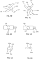
FIGS. 4A-E are exemplary views of cable cutters according to different examples. -
FIGS. 5A-B are exemplary views of cable cutters according to different examples. -
FIG. 6A-B are exemplary set of electrical cables according to different examples. - The detailed description set forth below provides information and examples of the disclosed technology with sufficient detail to enable those skilled in the art to practice the disclosure.
-
FIG. 1 is an exemplary marineelectrical drive system 100 according to an example. The drive system is configured to be comprised on amarine vessel 1. Themarine drive system 100 comprises anelectrical machine 130 and an electricalenergy storage system 150. In the example, theelectrical machine 130 is an electric pod drive. Theelectric machine 130 is arranged below a water level w. Theelectrical machine 130 comprises anelectric motor 140 which is connected with theenergy storage system 150. Theenergy storage system 150 is arranged onboard themarine vessel 1. Theenergy storage system 150 may be a battery pack. - The inventors of the present invention has realized that there is a need to have a last-resort safety function in the case that the
marine vessel 1 is encountering a high impact (for example by hitting a rock) that is deforming or in other way destroying parts of theelectrical drive system 100. Acable cutter 120 configured to cut at least one electric cable that is connecting theelectrical machine 130 and the electricalenergy storage system 150 is thus provided. By cutting the cable(s) at a high impact the damages caused can be reduced. Cutting the cables allows theelectrical machine 130 to be separated from the marine vessel. Before turning into details regarding thecutter 120 the other parts of the system will be described. In one example, thecable cutter 120 is positioned such the cables are cut in a way so they don't interfere when the drive leg/fixture is disconnected from the upper part of the system. In one example, thecable cutter 120 is arranged such that the drive leg (fixture) or parts of the drive leg is torn away from the vessel in a well-defined breach. This reduces the risk of breaking the vessel so that it starts taking in water. In other words, the cables are cut so that they are not pulled out during an impact causing a mess. - Some marine vessels are arranged with emergency switches, that electronically deactivates the electrical circuits in the system. However, the inventors of the present invention has realized that it is beneficial to also be able to cut the cable(s) so that the mechanical connection ceases to exist. In this way, the electrical machine, arranged under water, can be cut free from the rest of the marine vessel. The mechanical cut of the cable also ensures that no electrical faults occurs that could trigger other accidents, such as for example an electrical fire.
-
FIG. 2 shows an exemplaryelectric machine 130. Theelectric machine 130 comprises anelectric motor 140. Theelectric motor 140 is driving adrive shaft 142. Theelectric machine 130 further comprises at least onepropeller 132. Theelectric motor 140 is configured to drive thepropeller 132. Theelectric motor 140 may be directly connected with the propeller or it may be indirectly connected withpropeller 132. Ashaft 142 may be arranged between theelectric motor 140 and thepropeller 132 for providing torque and rotation to thepropeller 132. Thepropeller 132 is detachably mounted to thedrive shaft 142. Thepropeller 132 may be interchangeable. - Moreover, a transmission may be arranged between the
electric motor 140 and thepropeller 132 for ensuring that the intended torque is provided to thepropeller 132. In addition, thepropeller 132 may be connected with theshaft 142 via apropeller hub 133, or theelectric motor 140 is directly connected to the propeller hub. - In the example, the
propeller 132 has twoblades - The
propeller 132 may be a pusher propeller. The drive system is mounted to the structure onboard the vessel in such a direction that thepusher propeller 132 appears in an astern direction of the vessel. - The
propeller 132 may be a puller propeller. The drive system is mounted to the structure onboard the vessel in such a direction that thepuller propeller 132 appears in a forward direction of the vessel. - The
propeller 132 may be a folding propeller, having a folded position and an unfolded position. The folded position is a closed position where a minimum of drag is provided, and the unfolded position is an open position where a maximum of thrust, when used in a driving mode to provide propulsion to the marine vessel. - The
control unit 135 is operatively connected with theelectric motor 140. Thecontrol unit 135 is configured to control theelectric motor 140 to apply torque to thepropeller 132. - The
electric machine 130 further comprises anelongate housing 131 that encapsulates at least theelectric motor 140. In a preferred example, theelongate housing 131 further encapsulates thedrive shaft 142. - The
elongate housing 131 may havedistal end portions distal end portions distal end portions distal end portions housing 131 from galvanic corrosion in water. Such a material may be a sacrificing anode material, for example zinc, aluminum or magnesium alloys. - The
elongate housing 131 is connected to adrive leg 134. The drive leg will herein after be referred to afixture 134. Thefixture 134 is arranged on an upper side of theelongate housing 131 and extending up to theenergy storage system 150. Thefixture 134 may extend from the pod arrangement up to the hull attachment. In other words, the fixture covers the part of the system that is arranged in the water and that is between the pod arrangement and the hull. The fixture (drive leg) 134 connects to the boat's structure, possibly via a steering mechanism. A steering mechanism may be used if the drive is to be rotated around a vertical axis to steer the boat and direct the thrust of the propeller. As soon will be discussed more in detail, this is the portion of the fixture that will be disconnected from the vessel upon a severe impact. - Although not illustrated, the
fixture 134 may be arranged with an inverter. If the inverter is arranged in thefixture 134 it will be arranged close to the motor, which is preferable. If the inverter is arranged in the fixture, electrical cables may be arranged from the battery(s), via thecutter 120, to the inverter, and then from the inverter to the electric motor. - In some examples the inverter is instead arranged on the vessel, and not in the pod arrangement or in the fixture. If the invertor is arranged in the vessel electrical cables may be arranged from the inverter, via the cutter, to the electric motor.
- The
marine drive system 100 may also comprises acontrol unit 135. In the exemplary illustration ofFIG. 2 , thecontrol unit 135 is arranged in theelectric machine 130. However, thecontrol unit 135 may be arranged in other parts of thedrive system 100. Moreover, thedrive system 100 may comprises a plurality of control units. - The
electric motor 140 may have diagnostic data such as revolutions per minute (rpm) and/or armature currents (torque). Thecontrol unit 135 may be configured to monitor the diagnostic data received from theelectric motor 140. Moreover, a speed log, a true water speed sensor, a wind speed sensor and/or a positioning unit may be operatively connected with thecontrol unit 135. The speed log, the true water speed sensor, the wind speed sensor and/or the positioning unit may provide sensor data. The positioning unit may be a Global Positioning System (GPS). - In addition, an inertial navigation system may also be operatively connected with the control unit. The inertial navigation system may provide inertial measurement sensor data. The
control unit 135 may be configured to compare the diagnostic data from theelectric motor 140 with sensor data of any of the speed log, the true water speed sensor, the wind speed sensor and/or the positioning unit. Also, thecontrol unit 135 may be configured to compare the diagnostic data from theelectric motor 140 with the inertial measurement sensor data and/or the positioning data from a positioning unit. - In addition, the
control unit 135 may be configured to combine the diagnostic data received from theelectric motor 140 and sensor data so as to present the combined data via a user interface comprising presentation and control elements, such as displays, actuators, buttons, levers and smart device apps via gateways for protocols such as Bluetooth and Wi-Fi. Hereby, the captain or operator of themarine vessel 1 may be presented with information about the current generated power at a given speed, etc. -
FIGS. 3A-B are exemplary marineelectrical drive system 100 according to two examples. As soon will be discussed in detail, the two examples differ in the position of the at least onecutter 120. - The inboard electrical
energy storage system 150 is connected to theelectric machine 130 via at least oneelectric cable 152. In the example, one cable is present however it should be understood by a person skilled in the art that it could be a plurality of cables. This is also illustrated inFIGS. 6A-B . The cables could be arranged in a bundle of cables or as separate independent cables. The electrical cable provides electrical power supply to theelectric motor 140. The electrical cable may further be used to transmit signals and data between theelectric machine 130 and the inboard electricalenergy storage system 150. - The
cable 152 may be arranged through an opening in thefixture 134 that is arranged between the electricalenergy storage system 150 and theelectrical machine 130. In one example, thefixture 134 is a non-solid structure, so that the cables may run freely inside the fixture. The cable(s) are connected by cable connecters. The cable connectors may be rigid solutions. The cable connectors may be arranged where the fixture (drive leg) 134 connects to the boat's structure. - The
cable cutter 120 is used to cut the at least onecable 152 once the system recognize an impact acting on the vessel. If such an impact occurs, thecable cutter 120 cuts at least the cable connecting theelectric motor 140 and the inboard electricalenergy storage system 150. Thecable cutter 120 thus mechanically switches the electrical system off, at least partially. In a preferred example, thecable cutter 120 acts mechanically on the at least onecable 152. - As shown in the illustrative example of
FIG. 3A , the at least onecutter 120 is arranged on a lower side of the inboard electricalenergy storage system 150. The lower side is to be seen as the side facing the water level w. The at least onecutter 120 may be arranged inside thefixture 131. - As shown in the illustrative example of
FIG. 3B , the at least onecutter 120 is arranged on an upper side of the inboard electricalenergy storage system 150. The upper side is to be seen as the side facing away from the water level w. The at least onecutter 120 may be arranged inside the inboard electricalenergy storage system 150. - The
cable cutter 120 may have a plurality of different designs. This is illustrated in FIGS. 4A - 4G. - In the illustrative example of
FIG. 4A , thecable cutter 120 comprises at least oneblade 123 arranged to cut thecable 135. The at least oneblade 123 is at least partly arranged in amain body 121. Themain body 121 is arranged with anopening 122. In this example the opening is a hole. Theopening 122 is preferably of such dimension that the at least onecable 135 is able to be arranged therein. During normal operation, when no impact has occurred, the at least onecable 135 is arranged therein in a way that does not damage the cable (i.e. without putting too much pressure on the cable). - The
blade 123 has twoend portions first end portion 123a is arranged to cut thecable 135. Thefirst end portion 123a is at least partly arranged in theopening 122. Thesecond end portion 123b is arranged opposite thefirst end portion 123b. - In the present example, the
blade 123 is movably arranged in thebody 121. Theblade 123 is movable in the direction as indicated by the arrow. Theblade 123 is movable towards the opening 122 of thebody 121. Once theblade 123 is moved, the at least onecable 135 will be cut by theblade 123 is it will be clamped within the opening and theblade 123. - In the example of
FIG. 4B , thebody 121 of thecutter 120 is divided in twosections sections hinge 124. The at least onehinge 124 allows theupper section 121b to be opened in order to easier arranged the at least one cables therein. However, as should be understood thecables 135 could also be fed through the opening during manufacturing process. - In the example of
FIG. 4C , themain body 121 is arranged with twoblades blades blade first blade 123 is arranged to be arranged slightly above thesecond blade 124, or vice versa. This is illustrated in the enlarged view ofFIG. 4C . - In the examples of
FIGS. 4A-C , the first end portion of the blade/blades may have a rounded shape. The shape is preferably concave. This is best shown inFig. 4C . -
FIG. 4D illustrates one embodiment of acable cutter 120. The cable cutter has twoblades portions 127. Thehandle portions 127 may be connected by aspring 128. Thecable cutter 120 is activated by applying a force onto the handles so that they are pressed together. In this example thecable cutter 120 acts as a scissor or pruning shears. -
FIG. 4E illustrates asimilar cable cutter 120 as inFIG. 4D . In this example, the cable cutter further comprises a supportingsurface 129. The supporting surface helps keep the cables inside the cutter. - In one embodiment, the
cable cutter 120 according to all above examples, is configured to be arranged in a passive state and an active state. In the passive state, theblade 123 is not cutting the cable(s). The passive state is the normal configuration during use of themarine vessel 1. In the active state, the blade(s) is cutting the cable(s) by moving the blade(s). Hence, in the active state the movement of the blade(s) is activated. The active state of thecable cutter 120 should only be used in situations where a severe impact on the vessel has occur. Thecable cutter 120 will mechanically cut the connection between theelectric machine 130 and the inboard electricalenergy storage system 150. Once thecable cutter 120 is used, the cables will have to be replaced in order to drive the marine vessel once more. - In the above examples, the movement of the blade 123 (i.e. the active state of the cutter) may be activated in several ways. As in the examples of
FIGS. 4A-C , theblade 123 may be activated upon a force acting on theend portion 123b of theblade 123. The force may be generated by a spring, piston, orother structure 126 that activates during an impact, this is illustratively shown inFIGS. 5A-B . - The
end portion 123b of the blade could be activated, i.e. start to move, once thefixture 134 is deformed. The deformation of thefixture 134 may generate a direct force on theend portion 123b of theblade 123, or generate an indirect force on theend portion 123b of theblade 123, for example via astructure 126 such as a spring etc.. In one embodiment, theend portion 123b of the blade could be activated based on a force generated once a switch is activated. -
FIGS. 5A-B illustrates acutter 120 with astructure 126 that activates the at least oneblade 123 during direct or indirect impact according to two examples. As mention above, thestructure 126 could for example be a loaded spring or a piston. This is illustrated inFIG. 5A . - Yet further, the cable cutter could be driven and activated by a structure being an
ignition system 126. This is illustratively shown inFIG. 5B . Theignition system 126 may initiate a chemical reaction upon impact (either by the force generated or indirectly by a switch) that produces gas and inflates anactivator 126b. Theactivator 126b adds a force to thecable cutter 120 thus putting it in an active mode. In one example, theactivator 126b activates astructure 126a that causes a force onto the blade(s) 123. In one example the ignition system comprises a squib, a small igniter that produces a spark, a canister containing sodium axide, and a stable compound that rapidly decomposes when subjected to high temperatures. - As should be understood by a person skilled in the art, other types of
cable cutters 120 could be used. For example, the cable cutter could for example be driven by compressed air. The cable cutter could also be electrically driven. - As have been briefly discussed above, the
cable cutter 120 may be connected to at least oneswitch 122. If theswitch 122 is triggered, thecutter 120 is activated. Theswitch 122 is preferably arranged on theelongate housing 131. In one embodiment, oneswitch 122 is arranged on adistal end portion 131a of theelongate housing 131. As should be understood, the one or more switches may be arranged at other positions as well that are suitable to detect an impact. It should be noted that theswitch 122 may be arranged on thefixture 134. Moreover, thesystem 100 may comprise a plurality ofswitches 122 arranged at different positions. In one example, oneswitch 122 is arranged on thehousing 131 and one switch is arranged on thefixture 134. - The
switch 122 may be a mechanical impact switch. If any mechanical force acts on thevessel 1 in excess of a predetermined threshold value, thecutter 120 is activated by the switch. Theelongate housing 131, on which the switch is arranged, is deformed by the impact, whereupon the switch is triggered. - It should be noted that in some examples the
cable cutter 120 is suitable to cut one single cable. In that case, the electrical drive system may compriseseveral cable cutters 120. Other configurations are also possible, where for example the system comprises two cable cutters where onecable cutter 120 is arranged to cut two cables and onecable cutter 120 is arranged to cut one cable. -
FIGS. 6A - B are two exemplary top views ofcables 152 arranged between the inboard electricalenergy storage system 150 is connected to theelectric machine 130. In the example ofFIG. 6A , afist cable 152a is a power cable, the second andthird cables power cable 152a has a wider dimension that thecontrol cables main cable 152d that encloses the other cables. - In the example of
FIG. 6B , afist cable 152a is a power cable, the second andthird cables - The cable(s) 152 may be a power cable that carry high-voltage electricity. The power cable may for example utilize a cross-linked polyethylene insulation (XLPE) that offers good resistance to moisture. The at least one
cable 152 could also, or alternatively, be a control cable that transmit signals and data between the different units and/or a monitoring cables that provides continuous monitoring of various parameters (such as for example, temperature, pressure and vibration). Such cable could for example be a fiber optic cable. The cable may further be a communication cable that facilities communication between the different units. The cable(s) 152 should be suitable to be used in water. The cable(s) could also be referred to as at least one power supply line. - In one example, the system comprises three cables, one power cable and two control cables having a smaller dimension than the power cables. The system further comprises one
cable cutter 120 arranged to cut the power cable, and one cable cutter arranged to cut the two control cables. It is beneficial if the cable cutters are of suitable dimensions for the cables they are arranged to cut. Hence, in this example the cable cutter used to cut the power cables is bigger in dimension than the cable cutter used to cut the control cables. - A method of activating the cable cutter will now be described. The marine vessel is receiving an external force, causing an impact on the vessel. This may generate different actions, as will be described below.
- In one example, the fixture connecting the electrical energy storage system and the electric machine is deformed. The deformation of the fixture causes a force onto the at least one cable cutter. This force puts the cable cutter into an active state. In the active state, the cable cutter cuts the at least one cable connecting the electrical energy storage system and the electric machine.
- In one example, the housing of the electric machine is receiving a force. The force causes a deformation on the electric machine. The deformation of the housing causes a force onto the at least one cable cutter. This force puts the cable cutter into an active state. In the active state, the cable cutter cuts the at least one cable connecting the electrical energy storage system and the electric machine.
- In one example, the fixture connecting the electrical energy storage system and the electric machine and the housing of the electrical machine is deformed. The deformation causes an activation of the cable cutter, so that the cable cuts at least one cable.
- In one example, the housing of the electric machine is receiving a force. The force activates a switch arranged on the housing. The activation of a switch causes a force onto the at least one cable cutter. This force puts the cable cutter into an active state. In the active state, the cable cutter cuts the at least one cable connecting the electrical energy storage system and the electric machine.
- In one example, the fixture connecting the electrical energy storage system and the electric machine is receiving a force. The force activates a switch arranged on the fixture. The activation of a switch causes a force onto the at least one cable cutter. This force puts the cable cutter into an active state. In the active state, the cable cutter cuts the at least one cable connecting the electrical energy storage system and the electric machine.
- In one example, a plurality of switches, arranged at different parts in the system, causes the activation of the cutter.
- Certain aspects and variants of the disclosure are set forth in the following examples numbered consecutive below.
- Example 1: An electrical drive system (100) for a marine vessel (1), comprising: an electric machine (130) arranged below a water level (w), an inboard electrical energy storage system (150), wherein the electric machine (130) is connected to the inboard electrical energy storage system (150) via at least one electric cable (152); and at least one cable cutter (120) arranged to cut the at least one electric cable (152) in the event of impact.
- Example 2: The electrical drive system (100) of example 1, further comprising an elongate housing (131) which encapsulates at least an electric motor (140) of the electric machine (130).
- Example 3: The electrical drive system (100) of example 2, wherein the elongate housing (131) has a distal end portion (131a).
- Example 4: The electrical drive system (100) of example 3, wherein the distal end portion (131a) is cone-shaped.
- Example 5: The electrical drive system (100) of any of the preceding examples, further comprising a mechanical switch (122), wherein the cable cutter (120) is activated by said mechanical switch (122) upon impact.
- Example 6: The electrical drive system (100) of example 3 and 5, wherein the switch (122) is arranged in said distal end portion (131a).
- Example 7: The electrical drive system (100) of any of the preceding examples, further comprising a fixture (134) arranged to connect the electric machine (130) and the inboard electrical energy storage system (150), wherein the at least one electric cable (152) is arranged in said fixture (134).
- Example 8: The electrical drive system (100) of example 7, wherein the cable cutter (120) is arranged in said fixture (134).
- Example 9: The electrical drive system (100) of example 7 or 8, wherein the cable cutter (120) is activated once the fixture is deformed due to said impact.
- Example 10: The electrical drive system (100) of any of the preceding examples, wherein the cable cutter (120) is mechanically driven.
- Example 11: The electrical drive system (100) of any of the preceding examples, wherein the cable cutter (120) comprises a spring-loaded part.
- Example 12: The electrical drive system (100) of any of the preceding examples, wherein the cable cutter (120) comprises a guillotine cutter.
- Example 13: The electrical drive system (100) of any of the preceding examples, wherein the cable cutter (120) is configured to be arranged in a passive state and an active state, wherein the cable cutter (120) is put in the active state in the event of an impact.
- Example 14: The electrical drive system of any of the preceding examples, wherein the cutter is arranged adjacent to the inboard electrical energy storage system.
- Example 15: The electrical drive system of any of the preceding examples, wherein the inboard electrical energy storage system is a battery.
- Example 16: The electrical drive system of any of the preceding examples, wherein the cable cutter comprises at least one blade.
- Example 17: The electrical drive system of any of the preceding examples, wherein the cable cutter is arranged to cut all electrical cables.
- Example 18: The electrical drive system of any of the examples 1 - 16, further comprising at least a first cable cutter and a second cable cutter and at least a first cable and a second cable, where the first cable cutter is arranged to cut the first cable and the second cable cutter is arranged to cut the second cable.
- Example 14: A marine propulsion system for a marine vessel, comprising an electrical drive system (100) according to any of the preceding examples.
- Example 15: A marine vessel (1) comprising an electrical drive system (100) of any of the examples 1 to 13 and/or a marine propulsion system according to example 14.
- The terminology used herein is for the purpose of describing particular aspects only and is not intended to be limiting of the disclosure. As used herein, the singular forms "a," "an," and "the" are intended to include the plural forms as well, unless the context clearly indicates otherwise. As used herein, the term "and/or" includes any and all combinations of one or more of the associated listed items. It will be further understood that the terms "comprises," "comprising," "includes," and/or "including" when used herein specify the presence of stated features, integers, actions, steps, operations, elements, and/or components, but do not preclude the presence or addition of one or more other features, integers, actions, steps, operations, elements, components, and/or groups thereof.
- It will be understood that, although the terms first, second, etc., may be used herein to describe various elements, these elements should not be limited by these terms. These terms are only used to distinguish one element from another. For example, a first element could be termed a second element, and, similarly, a second element could be termed a first element without departing from the scope of the present disclosure.
- Relative terms such as "below" or "above" or "upper" or "lower" or "horizontal" or "vertical" may be used herein to describe a relationship of one element to another element as illustrated in the Figures. It will be understood that these terms and those discussed above are intended to encompass different orientations of the device in addition to the orientation depicted in the Figures. It will be understood that when an element is referred to as being "connected" or "coupled" to another element, it can be directly connected or coupled to the other element, or intervening elements may be present. In contrast, when an element is referred to as being "directly connected" or "directly coupled" to another element, there are no intervening elements present.
- Unless otherwise defined, all terms (including technical and scientific terms) used herein have the same meaning as commonly understood by one of ordinary skill in the art to which this disclosure belongs. It will be further understood that terms used herein should be interpreted as having a meaning consistent with their meaning in the context of this specification and the relevant art and will not be interpreted in an idealized or overly formal sense unless expressly so defined herein.
- It is to be understood that the present disclosure is not limited to the aspects described above and illustrated in the drawings; rather, the skilled person will recognize that many changes and modifications may be made within the scope of the present disclosure and appended claims. In the drawings and specification, there have been disclosed aspects for purposes of illustration only and not for purposes of limitation, the scope of the disclosure being set forth in the following claims.
Claims (15)
- An electrical drive system (100) for a marine vessel (1), comprising:an electric machine (130) arranged below a water level (w);an inboard electrical energy storage system (150), wherein the electric machine (130) is connected to the inboard electrical energy storage system (150) via at least one electric cable (152); andat least one cable cutter (120) arranged to cut the at least one electric cable (152) in the event of impact.
- The electrical drive system (100) of claim 1, further comprising an elongate housing (131) which encapsulates at least an electric motor (140) of the electric machine (130).
- The electrical drive system (100) of claim 2, wherein the elongate housing (131) has a distal end portion (131a).
- The electrical drive system (100) of claim 3, wherein the distal end portion (131a) is cone-shaped.
- The electrical drive system (100) of any of the preceding claims, further comprising a mechanical switch (122), wherein the cable cutter (120) is activated by said mechanical switch (122) upon impact.
- The electrical drive system (100) of claim 3 and 5, wherein the switch (122) is arranged in said distal end portion (131a).
- The electrical drive system (100) of any of the preceding claims, further comprising a fixture (134) arranged to connect the electric machine (130) and the inboard electrical energy storage system (150), wherein the at least one electric cable (152) is arranged in said fixture (134).
- The electrical drive system (100) of claim 7, wherein the cable cutter (120) is arranged in said fixture (134).
- The electrical drive system (100) of claim 7 or 8, wherein the cable cutter (120) is activated once the fixture is deformed due to said impact.
- The electrical drive system (100) of any of the preceding claims, wherein the cable cutter (120) is mechanically driven.
- The electrical drive system (100) of any of the preceding claims, wherein the cable cutter (120) comprises a spring-loaded part.
- The electrical drive system (100) of any of the preceding claims, wherein the cable cutter (120) comprises a guillotine cutter.
- The electrical drive system (100) of any of the preceding claims, wherein the cable cutter (120) is configured to be arranged in a passive state and an active state, wherein the cable cutter (120) is put in the active state in the event of an impact.
- A marine propulsion system for a marine vessel, comprising an electrical drive system (100) according to any of the preceding claims.
- A marine vessel (1) comprising an electrical drive system (100) of any of the claims 1 to 13 and/or a marine propulsion system according to claim 14.
Priority Applications (2)
| Application Number | Priority Date | Filing Date | Title |
|---|---|---|---|
| EP23219990.1A EP4574640A1 (en) | 2023-12-22 | 2023-12-22 | A marine drive unit |
| US18/978,217 US20250206429A1 (en) | 2023-12-22 | 2024-12-12 | Marine drive unit |
Applications Claiming Priority (1)
| Application Number | Priority Date | Filing Date | Title |
|---|---|---|---|
| EP23219990.1A EP4574640A1 (en) | 2023-12-22 | 2023-12-22 | A marine drive unit |
Publications (1)
| Publication Number | Publication Date |
|---|---|
| EP4574640A1 true EP4574640A1 (en) | 2025-06-25 |
Family
ID=89322005
Family Applications (1)
| Application Number | Title | Priority Date | Filing Date |
|---|---|---|---|
| EP23219990.1A Withdrawn EP4574640A1 (en) | 2023-12-22 | 2023-12-22 | A marine drive unit |
Country Status (2)
| Country | Link |
|---|---|
| US (1) | US20250206429A1 (en) |
| EP (1) | EP4574640A1 (en) |
Citations (3)
| Publication number | Priority date | Publication date | Assignee | Title |
|---|---|---|---|---|
| US8944865B1 (en) * | 2013-01-24 | 2015-02-03 | Brunswick Corporation | Water sensing interlock systems and methods for hybrid marine vessels |
| US20160214534A1 (en) * | 2014-09-02 | 2016-07-28 | FLIR Belgium BVBA | Watercraft thermal monitoring systems and methods |
| JP2021154946A (en) * | 2020-03-27 | 2021-10-07 | ヤマハ発動機株式会社 | Marine power supply system, and control method of marine power supply system |
-
2023
- 2023-12-22 EP EP23219990.1A patent/EP4574640A1/en not_active Withdrawn
-
2024
- 2024-12-12 US US18/978,217 patent/US20250206429A1/en active Pending
Patent Citations (3)
| Publication number | Priority date | Publication date | Assignee | Title |
|---|---|---|---|---|
| US8944865B1 (en) * | 2013-01-24 | 2015-02-03 | Brunswick Corporation | Water sensing interlock systems and methods for hybrid marine vessels |
| US20160214534A1 (en) * | 2014-09-02 | 2016-07-28 | FLIR Belgium BVBA | Watercraft thermal monitoring systems and methods |
| JP2021154946A (en) * | 2020-03-27 | 2021-10-07 | ヤマハ発動機株式会社 | Marine power supply system, and control method of marine power supply system |
Also Published As
| Publication number | Publication date |
|---|---|
| US20250206429A1 (en) | 2025-06-26 |
Similar Documents
| Publication | Publication Date | Title |
|---|---|---|
| EP3508426A1 (en) | Small flying body provided with airbag device | |
| US8944865B1 (en) | Water sensing interlock systems and methods for hybrid marine vessels | |
| JP5521708B2 (en) | Electric outboard motor | |
| JP5477118B2 (en) | Electric outboard motor | |
| US20150047548A1 (en) | Hand-held underwater propulsion system | |
| CN111003119A (en) | Positioning rescue device of unmanned underwater vehicle | |
| EP2593356B1 (en) | A propulsion unit for a marine vessel and a marine vessel having a propulsion unit | |
| US20250206429A1 (en) | Marine drive unit | |
| EP4585503A1 (en) | Electric outboard motor for watercraft | |
| US7195525B2 (en) | Outboard motor | |
| CN201924961U (en) | Amphibious telerobot for mine disaster rescue | |
| CN214566080U (en) | Novel series vector propeller for shallow water underwater robot | |
| US12263917B2 (en) | Parachute sea anchor | |
| CN103857587B (en) | Disconnection unit for the instantaneous disconnection of load | |
| JP5454309B2 (en) | Electric outboard motor | |
| KR102767328B1 (en) | Underwater Cutting Apparatus on Screw of Small Boat | |
| CN212951028U (en) | Marine ship engineering positioning device | |
| KR102163923B1 (en) | Ship Obstacle Removal Device Using Pneumatic Motor | |
| CN215590977U (en) | Adjustable oar of boats and ships | |
| CN114883738A (en) | Protection device for deep sea submersible battery compartment and control method | |
| CN111252225A (en) | Underwater detection robot | |
| CN105793155B (en) | Water propeller | |
| JP7556826B2 (en) | Safety device and flying object equipped with the safety device | |
| CN213620270U (en) | Screw propeller with warning function | |
| CN218949434U (en) | Mini electric card Ding Chuan |
Legal Events
| Date | Code | Title | Description |
|---|---|---|---|
| PUAI | Public reference made under article 153(3) epc to a published international application that has entered the european phase |
Free format text: ORIGINAL CODE: 0009012 |
|
| STAA | Information on the status of an ep patent application or granted ep patent |
Free format text: STATUS: REQUEST FOR EXAMINATION WAS MADE |
|
| 17P | Request for examination filed |
Effective date: 20250212 |
|
| AK | Designated contracting states |
Kind code of ref document: A1 Designated state(s): AL AT BE BG CH CY CZ DE DK EE ES FI FR GB GR HR HU IE IS IT LI LT LU LV MC ME MK MT NL NO PL PT RO RS SE SI SK SM TR |
|
| GRAP | Despatch of communication of intention to grant a patent |
Free format text: ORIGINAL CODE: EPIDOSNIGR1 |
|
| STAA | Information on the status of an ep patent application or granted ep patent |
Free format text: STATUS: GRANT OF PATENT IS INTENDED |
|
| RIC1 | Information provided on ipc code assigned before grant |
Ipc: B63B 43/18 20060101AFI20251010BHEP Ipc: B63B 43/20 20060101ALI20251010BHEP Ipc: B63H 21/17 20060101ALI20251010BHEP |
|
| INTG | Intention to grant announced |
Effective date: 20251024 |
|
| STAA | Information on the status of an ep patent application or granted ep patent |
Free format text: STATUS: THE APPLICATION IS DEEMED TO BE WITHDRAWN |
|
| 18D | Application deemed to be withdrawn |
Effective date: 20260225 |