EP4574626A2 - Foldable and movable carrier - Google Patents
Foldable and movable carrier Download PDFInfo
- Publication number
- EP4574626A2 EP4574626A2 EP25176089.8A EP25176089A EP4574626A2 EP 4574626 A2 EP4574626 A2 EP 4574626A2 EP 25176089 A EP25176089 A EP 25176089A EP 4574626 A2 EP4574626 A2 EP 4574626A2
- Authority
- EP
- European Patent Office
- Prior art keywords
- rod
- mating portion
- rotating sector
- locking
- groove
- Prior art date
- Legal status (The legal status is an assumption and is not a legal conclusion. Google has not performed a legal analysis and makes no representation as to the accuracy of the status listed.)
- Pending
Links
Images



Classifications
-
- B—PERFORMING OPERATIONS; TRANSPORTING
- B62—LAND VEHICLES FOR TRAVELLING OTHERWISE THAN ON RAILS
- B62B—HAND-PROPELLED VEHICLES, e.g. HAND CARTS OR PERAMBULATORS; SLEDGES
- B62B7/00—Carriages for children; Perambulators, e.g. dolls' perambulators
- B62B7/04—Carriages for children; Perambulators, e.g. dolls' perambulators having more than one wheel axis; Steering devices therefor
- B62B7/06—Carriages for children; Perambulators, e.g. dolls' perambulators having more than one wheel axis; Steering devices therefor collapsible or foldable
-
- B—PERFORMING OPERATIONS; TRANSPORTING
- B62—LAND VEHICLES FOR TRAVELLING OTHERWISE THAN ON RAILS
- B62B—HAND-PROPELLED VEHICLES, e.g. HAND CARTS OR PERAMBULATORS; SLEDGES
- B62B7/00—Carriages for children; Perambulators, e.g. dolls' perambulators
- B62B7/04—Carriages for children; Perambulators, e.g. dolls' perambulators having more than one wheel axis; Steering devices therefor
- B62B7/06—Carriages for children; Perambulators, e.g. dolls' perambulators having more than one wheel axis; Steering devices therefor collapsible or foldable
- B62B7/062—Coupling unit between front wheels, rear wheels and handle
-
- B—PERFORMING OPERATIONS; TRANSPORTING
- B62—LAND VEHICLES FOR TRAVELLING OTHERWISE THAN ON RAILS
- B62B—HAND-PROPELLED VEHICLES, e.g. HAND CARTS OR PERAMBULATORS; SLEDGES
- B62B7/00—Carriages for children; Perambulators, e.g. dolls' perambulators
- B62B7/04—Carriages for children; Perambulators, e.g. dolls' perambulators having more than one wheel axis; Steering devices therefor
- B62B7/06—Carriages for children; Perambulators, e.g. dolls' perambulators having more than one wheel axis; Steering devices therefor collapsible or foldable
- B62B7/064—Carriages for children; Perambulators, e.g. dolls' perambulators having more than one wheel axis; Steering devices therefor collapsible or foldable the handle bar being parallel to the front leg
-
- B—PERFORMING OPERATIONS; TRANSPORTING
- B62—LAND VEHICLES FOR TRAVELLING OTHERWISE THAN ON RAILS
- B62B—HAND-PROPELLED VEHICLES, e.g. HAND CARTS OR PERAMBULATORS; SLEDGES
- B62B7/00—Carriages for children; Perambulators, e.g. dolls' perambulators
- B62B7/04—Carriages for children; Perambulators, e.g. dolls' perambulators having more than one wheel axis; Steering devices therefor
- B62B7/06—Carriages for children; Perambulators, e.g. dolls' perambulators having more than one wheel axis; Steering devices therefor collapsible or foldable
- B62B7/08—Carriages for children; Perambulators, e.g. dolls' perambulators having more than one wheel axis; Steering devices therefor collapsible or foldable in the direction of, or at right angles to, the wheel axis
-
- B—PERFORMING OPERATIONS; TRANSPORTING
- B62—LAND VEHICLES FOR TRAVELLING OTHERWISE THAN ON RAILS
- B62B—HAND-PROPELLED VEHICLES, e.g. HAND CARTS OR PERAMBULATORS; SLEDGES
- B62B2205/00—Hand-propelled vehicles or sledges being foldable or dismountable when not in use
- B62B2205/20—Catches; Locking or releasing an articulation
Definitions
- a foldable and movable carrier which can prevent pivoting of the carrier after unintentional release of a locking mechanism, so as to facilitate the relocking and refixing of the movable carrier.
- the engaging groove is a V-shaped groove.
- the V-shaped groove includes a first groove wall and a second groove wall that are arranged in a V shape.
- the engaging protrusion is an arc-shaped protrusion capable of being tangent to the first groove wall and the second groove wall.
- an end of the first rod is provided with a first rotating sector.
- An end of the second rod is provided with a second rotating sector.
- the first rotating sector is opposite to the second rotating sector.
- the second position is disposed at a circle center of the first rotating sector.
- a circle center of the second rotating sector is pivotally connected to the first rotating sector in the second position.
- the first mating portion is disposed at a circumferential edge of a surface of the first rotating sector facing the second rotating sector.
- the second mating portion is disposed at a circumferential edge of a surface of the second rotating sector facing the first rotating sector.
- first rod; 101 first mating portion; 110, first position; 120, second position; 130, third position; 140, first rotating sector; 141, arc-shaped guiding groove; 150, engaging groove; 151, first groove wall; 152, second groove wall; 200, third rod; 300, second rod; 301, second mating portion; 310, second rotating sector; 311, arc-shaped guiding rib; 312, stopper; 320, engaging protrusion; 400, locking mechanism; 410, first locking shell; 411, first locking groove; 420, elastic member; 430, locking member; 431, locking teeth; 440, second locking shell; 441, through hole; 442, second locking groove; 450, releasing member; 451, pushing portion; 20, handle; 30, front support; 40, rear support.
- an embodiment of the present application provides a foldable and movable carrier.
- the foldable and movable carrier includes a first rod 100, a third rod 200, and a second rod 300.
- the carrier may be a stroller.
- the stroller includes a handle 20, a front support 30, and a rear support 40.
- the first rod 100, the third rod 200, and the second rod 300 are all hollow rods, and are respectively sleeved on an end of the handle 20, an end of the rear support 40, and an end of the front support 30.
- the first rod 100 includes a first position 110, a second position 120, and a third position 130 which are sequentially spaced apart in an extending direction of the first rod 100.
- the structure of the movable carrier of the present application is not limited to herein.
- the first rod 100 is sleeved on a bottom end of the handle 20.
- the first rod 100 can also be connected to the bottom end of the handle 20 or be formed as a part of the bottom end of the handle 20.
- a first mating portion 101 is disposed in the third position 130.
- the third rod 200 is pivotally connected to the first rod 100 in the first position 110 through the locking mechanism 400.
- the locking mechanism 400 has a locked state and an unlocked state.
- the first rod 100 and the third rod 200 are relatively fixed and arranged at a first preset included angle.
- the first rod 100 can rotate relative to the third rod 200.
- the third rod 200 is sleeved on a top end of the rear support 40.
- the third rod 200 can also be connected to the top end of the rear support 40 or be formed as a part of the top end of the rear support 40 by other means.
- the first preset included angle is an acute angle.
- the locking mechanism 400 includes a first locking shell 410, an elastic member 420, a locking member 430, a second locking shell 440, and a releasing member 450, which are arranged in sequence.
- the first locking shell 410 is fixed on the first rod 100 or is a part of the first rod 100.
- the first locking shell 410 includes a first locking groove 411.
- the second locking shell 440 is fixed on the third rod 200, or is formed as a part of the third rod 200.
- the second locking shell 440 includes a second locking groove 442.
- the locking member 430 includes at least two locking teeth 431 arranged at a predetermined angle.
- the elastic member 420 is operably connected to the locking member 430, for maintaining the locking member 430 in the locked state.
- the elastic member 420 is a spring. Two ends of the spring abut against the first locking shell 410 and the locking member 430, respectively.
- the releasing member 450 is operably connected to the locking member 430, for driving the locking member 430 to move against the elastic force of the elastic member 420 to switch the locking member 430 from the locked state to the unlocked state.
- the releasing member 450 is a release button.
- the release button is provided with a pushing portion 451.
- the second locking shell 440 is provided with a through hole 441 through which the pushing portion 451 can pass.
- the locking member 430 is locked into both the first locking shell 410 and the second locking shell 440 under the elastic force of the elastic member 420 that is a return spring.
- the first locking shell 410 and the second locking shell 440 are in the locked state, that is, the first rod 100 and the third rod 200 are in the locked state.
- the pushing portion 451 can pass through the through hole 441 to press the second locking shell 440 and the locking member 430, so that the locking member 430 is separated from the first locking groove 411 or the second locking groove 442.
- the first locking shell 410 and the second locking shell 440 are in the released state, that is, the first rod 100 can rotate relative to the third rod 200.
- the locking mechanism 400 has a simple structure and can enable the first rod 100 and the third rod 200 to switch between the locked state and the unlocked state.
- the first rod 100 will pivot under the action of external force or its own gravity, so that the locking teeth 431 of the locking member 430 are misaligned with the first locking groove 411 or the second locking groove 442, so that it is difficult for the locking member 430 to reengage into the first locking groove 411 or the second locking groove 442 such that the first locking shell 410 and the second locking shell 440 are in the locked state again. That is, it is difficult to bring the first rod 100 and the third rod 200 into a relatively locked and fixed state again.
- the second rod 300 is pivotally connected to the first rod 100 in the second position 120.
- the second rod 300 is provided with a second mating portion 301 detachably mating with the first mating portion 101.
- the first rod 100 and the second rod 300 are relatively fixed and arranged at a second preset included angle.
- the first rod 100 can rotate relative to the second rod 300, and an included angle facing the third rod 200, between the first rod 100 and the second rod 300 is less than or equal to the second preset included angle.
- the second preset included angle is 180 degrees.
- the first rod 100 and the second rod 300 are on the same straight line.
- the first preset included angle is an acute angle
- the locking mechanism 400 when the locking mechanism 400 is in the locked and fixed state, a combined structure of the first rod 100 and the second rod 300, and the third rod 200 form a triangular support structure.
- the included angle facing the third rod 200, between the first rod 100 and the second rod 300 is always kept less than or equal to the second preset included angle, that is, when the locking mechanism 400 is in the locked state, the first rod 100 can neither rotate from the third rod 200 to the second rod 300 nor from the second rod 300 to the third rod 200. Therefore, when the locking mechanism 400 is in the locked state, the first rod 100 and the second rod 300 can be kept at the first preset included angle, thereby providing a stable triangular support structure for the whole stroller.
- the first rod 100, the second rod 300, and the third rod 200 form a stable triangular support structure, so that the first rod 100 and the second rod 300 are relatively fixed, and the first rod 100 and the third rod 200 are also relatively fixed.
- the locking mechanism 400 is unintentionally pressed and unlocked, since the first mating portion 101 which mates with the second mating portion 301 of the second rod 300 is disposed in the third position 130 of the first rod 100, the first mating portion 101 mates with the second mating portion 301, the first rod 100 and the second rod 300 are still relatively fixed, and the first rod 100 will not pivot.
- the first rod 100 can be prevented from pivoting in a state of unintentional release such that the locking mechanism 400 cannot be restored to the locked state, and the first rod 100 and the second rod 300 cannot be locked and fixed.
- the locking mechanism 400 is unlocked, and a certain external force is applied to the first rod 100 at the same time, so that the first mating portion 101 and the second mating portion 301 are released from mating.
- the relative fixed state among the first rod 100, the third rod 200, and the second rod 300 can be released, and the foldable and movable carrier 10 can be folded.
- a bottom end of the first rod 100 is provided with a first rotating sector 140
- a top end of the second rod 300 is provided with a second rotating sector 310.
- the second position 120 is disposed at a circle center of the first rotating sector 140.
- a circle center of the second rotating sector 310 is pivotally connected to the first rotating sector 140 in the second position 120 (i.e., the circle center of the first rotating sector 140).
- a surface of the first rotating sector 140 facing the second rotating sector 310 is provided with at least two arc-shaped guiding grooves 141 that are concentric with the first rotating sector 140.
- a surface of the second rotating sector 310 facing the first rotating sector 140 is provided with at least two arc-shaped guiding ribs 311 that are concentric with the second rotating sector 310.
- the arc-shaped guiding ribs 311 mates with the arc-shaped guiding grooves 141 in one-to-one correspondence, to guide the rotations of the first rod 100 and the second rod 300, to facilitate the folding of the movable carrier. It can be understood that the locations of the arc-shaped guiding grooves 141 and the locations of the arc-shaped guiding ribs 311 can be interchanged.
- the first mating portion 101 is disposed at a circumferential edge of the surface of the first rotating sector 140 facing the second rotating sector 310
- the second mating portion 301 is disposed at a circumferential edge of the surface of the second rotating sector 310 facing the first rotating sector 140.
- a distance from the second position 120 to the third position 130 is relatively large.
- the lever principle when the movable carrier is folded, the external force required to be applied to release the mating between the first mating portion 101 and the second mating portion 301 is smaller, which means that less effort is required when the movable carrier is folded.
- first mating portion 101 and the second mating portion 301 can also be arranged according to actual needs.
- first mating portion 101 and the second mating portion 301 can be arranged closer to the circle center of the first rotating sector 140 and the circle center of the second rotating sector 310, respectively, so that when the locking mechanism 400 is unintentionally released, the first rod 100 is more difficult to pivot, etc., which is not limited to herein.
- a stopper 312 is disposed on a side of the second rotating sector 310 close to the third rod 200.
- the stopper 312 may be a stopping protrusion, a stopping slope, or the like.
- the stopper 312 is a stopping slope disposed at the circumferential edge of the surface of the second rotating sector 310 facing the first rotating sector 140, and the stopping slope is gradually raised in a direction of approaching the third rod 200. In this way, it can be ensured that the included angle facing the third rod 200, between the first rod 100 and the second rod 300 is always less than or equal to the second preset included angle.
- the first mating portion 101 is a male connecting portion
- the second mating portion 301 is a female connecting portion that can detachably mate with the male connecting portion.
- the first mating portion 101 is a female connecting portion
- the second mating portion 301 is a male connecting portion that can detachably mate with the female connecting portion.
- the first mating portion 101 is an engaging groove 150
- the second mating portion 301 is an engaging protrusion 320 capable of being engaged with the engaging groove 150.
- the first mating portion 101 can also be the engaging protrusion 320
- the second mating portion 301 can be the engaging groove 150 capable of being engaged with the engaging protrusion 320.
- the engaging groove 150 is disposed on the circumferential edge of the surface of the first rotating sector 140 facing the second rotating sector 310, and the engaging protrusion 320 is disposed on the circumferential edge of the surface of the second rotating sector 310 facing the first rotating sector 140.
- the engaging groove 150 may also be disposed in other positions of the first rotating sector 140, and the engaging protrusion 320 may also be disposed in other positions of the second rotating sector 310.
- the engaging groove 150 is a V-shaped groove.
- the V-shaped groove includes a first groove wall 151 and a second groove wall 152 that are arranged in a V shape.
- the engaging protrusion 320 is an arc-shaped protrusion capable of being tangent to the groove walls of the V-shaped groove. That is, a cross-sectional shape of the engaging groove 150 perpendicular to the first rod 100 is V-shaped, and a cross-sectional shape of the engaging protrusion 320 perpendicular to the third rod 200 is arc-shaped. In this way, when the first rod 100 rotates to be engaged and fixed to the third rod 200, the engaging protrusion 320 can be more smoothly engaged into the engaging groove 150.
- a first included angle between the first groove wall 151 and a plane where an opening of the V-shaped groove is located is in a range from 40° to 50°. In this embodiment, the first included angle is 45°.
- a second included angle between the second groove wall 152 and the plane where the opening of the V-shaped groove is located is in a range from 40° to 50°. In this embodiment, the second included angle is 45°.
- a height of the arc-shaped protrusion is in a range from 1.5mm to 2.5mm. In this embodiment, the height is 2mm.
- the engaging protrusion 320 is a serrated protrusion including at least two engaging teeth
- the engaging groove 150 is a serrated groove including at least two engaging grooves.
- the at least two engaging teeth can mate with the at least two engaging grooves one by one.
- the mating structure of the serrated protrusion and the serrated groove can provide a larger friction force, so that the first rod 100 has a stronger anti-pivoting ability during the unintentional release.
- the height of the serrated protrusion can be less than that of the single protrusion, and the depth of the corresponding engaging groove 150 can also be less than that of the single groove.
- the first mating portion 101 may be a plug hole
- the second mating portion 301 may be a plug pin capable of being plugged into the plug hole.
- the first mating portion 101 can also be a plug pin
- the second mating portion 301 can also be a plug hole capable of being plugged with the plug pin.
- a hole wall of the plug hole can be elastically deformed.
- an inner diameter of the plug hole is greater than a diameter of the plug pin.
- the plug pin can be elastically deformed.
- the diameter of the plug pin is less than the inner diameter of the plug hole; and when the plug pin is restored to its original state, the diameter of the plug pin is greater than the inner diameter of the plug hole.
- this configuration facilitates the plug pin plugging into the plug hole, and keeping the plug pin stably in the plug hole without easily coming out of the plug hole; and on the other hand, this configuration is also convenient for the plug pin to come out from the plug hole when external force is applied.
- both the first rod 100 and the second rod 300 are made of deformable plastic materials, so as to facilitate the mating and separation of the first mating portion 101 and the second mating portion 301.
- the above-mentioned foldable and movable carrier 10 at least have the following technical effects.
- the locking mechanism 400 When the locking mechanism 400 is unintentionally unlocked, since the first mating portion 101 and the second mating portion 301 are in a mating state, the first rod 100 pivotally connected to the second rod 300 is not easy to pivot, so that the user can reset the locking mechanism 400, and thus the movable carrier can be restored to the locked and fixed state, and as a result, the safety of the entire movable carrier can be improved.
- the locking mechanism 400 can be pressed, and the first mating portion 101 and the second mating portion 301 can be released from the mating, for example, by applying a certain external force, so that the first rod 100 can rotate and be folded relative to the second rod 300, to ensure the realization of the foldable function of the movable carrier.
- the subject-matter of the present invention relates, inter alia, to the following aspects:
Landscapes
- Engineering & Computer Science (AREA)
- Chemical & Material Sciences (AREA)
- Combustion & Propulsion (AREA)
- Transportation (AREA)
- Mechanical Engineering (AREA)
- Carriages For Children, Sleds, And Other Hand-Operated Vehicles (AREA)
- Pivots And Pivotal Connections (AREA)
- Handcart (AREA)
- Lock And Its Accessories (AREA)
Abstract
Description
- The present application relates to the technical field of carriers, in particular to a foldable and movable carrier.
- Rotatable and foldable carriers, such as foldable strollers, are easy to store and carry, but are also prone to potential safety hazards. According to the test requirements of the European Regulation EN1888-1:2018 (8.3.5.1 Test Standard for Folding System for Ease of storage or transportation), there shall be at least two separate and independent manual operating devices which fulfil the following conditions: where any one of the operating devices is released, it shall also automatically return to its original status and the locking device shall relock again. However, in the current stroller on the market, when, for example, a locking mechanism on a handle of the stroller is unintentionally pressed, the handle will pivot to a certain extent under the action of the child's weight or its own gravity, so that the locking mechanism cannot return to a locked position, causing certain safety hazards to the children in the stroller.
- Accordingly, a foldable and movable carrier is provided, which can prevent pivoting of the carrier after unintentional release of a locking mechanism, so as to facilitate the relocking and refixing of the movable carrier.
- According to an aspect of the present application, a foldable and movable carrier is provided, and includes:
- a locking mechanism having a locked state and an unlocked state;
- a first rod provided with a first mating portion; and
- a second rod pivotally connected to the first rod, and the second rod being provided with a second mating portion detachably mating with the first mating portion;
- wherein when the locking mechanism is in the locked state, the first rod and the second rod are relatively fixed. When the locking mechanism is in the unlocked state, if the first mating portion mates with the second mating portion, the first rod and the second rod are relatively fixed, if the first mating portion and the second mating portion are released from mating, the first rod is capable of rotating relative to the second rod, so as to fold or unfold the movable carrier.
- In the foldable and movable carrier, when the locking mechanism is unintentionally unlocked, since the first mating portion and the second mating portion are in a mating state, the first rod pivotally connected to the second rod will not pivot, so that the user can reset the locking mechanism, and thus the first rod can be restored to the locked state, and as a result, the safety of the entire foldable and movable carrier can be improved. In addition, when it is really necessary to release the locking, the locking mechanism can be pressed, and the first mating portion and the second mating portion can be released from the mating, for example, by applying a certain external force, so that the first rod can rotate and be folded relative to the second rod, to ensure the realization of the foldable function of the movable carrier.
- In one of the embodiments, the first mating portion is a male connecting portion, and the second mating portion is a female connecting portion capable of detachably mating with the male connecting portion. Or, the first mating portion is a female connecting portion, and the second mating portion is a male connecting portion capable of detachably mating with the female connecting portion.
- In one of the embodiments, one of the first mating portion and the second mating portion is an engaging groove; another one of the first mating portion and the second mating portion is an engaging protrusion capable of being engaged with the engaging groove.
- In one of the embodiments, the engaging groove is a V-shaped groove. The V-shaped groove includes a first groove wall and a second groove wall that are arranged in a V shape. The engaging protrusion is an arc-shaped protrusion capable of being tangent to the first groove wall and the second groove wall.
- In one of the embodiments, an included angle between the first groove wall and a plane where an opening of the V-shaped groove is located is in a range from 40° to 50°. An included angle between the second groove wall and the plane where the opening of the V-shaped groove is located is in a range from 40° to 50°. A height of the arc-shaped protrusion is in a range from 1.5mm to 2.5mm.
- In one of the embodiments, the engaging protrusion is a serrated protrusion including at least two engaging teeth. The engaging groove is a serrated groove including at least two engaging grooves. The at least two engaging teeth are capable of mating with the at least two engaging grooves one by one.
- In one of the embodiments, one of the first mating portion and the second mating portion is a plug hole; and another one of the first mating portion and the second mating portion is a plug pin capable of being plugged into the plug hole.
- In one of the embodiments, a hole wall of the plug hole is capable of being elastically deformed; when the hole wall of the plug hole is elastically deformed, an inner diameter of the plug hole is greater than a diameter of the plug pin; when the hole wall of the plug hole is restored to its original shape, the inner diameter of the plug hole is less than the diameter of the plug pin. Or, the plug pin is capable of being elastically deformed; when the plug pin is elastically deformed, a diameter of the plug pin is less than an inner diameter of the plug hole; and when the plug pin is restored to its original state, the diameter of the plug pin is greater than the inner diameter of the plug hole.
- In one of the embodiments, the foldable and movable carrier further includes a third rod. The first rod includes a first position, a second position, and a third position that are sequentially spaced apart in an extending direction of the first rod. The first mating portion is disposed in the third position. The third rod is pivotally connected to the first rod in the first position through the locking mechanism. When the locking mechanism is in the locked state, the first rod and the third rod are relatively fixed. When the locking mechanism is in the unlocked state, the first rod is capable of rotating relative to the third rod, so as to fold or unfold the movable carrier. The second rod is pivotally connected to the first rod in the second position.
- In one of the embodiments, an end of the first rod is provided with a first rotating sector. An end of the second rod is provided with a second rotating sector. The first rotating sector is opposite to the second rotating sector. The second position is disposed at a circle center of the first rotating sector. A circle center of the second rotating sector is pivotally connected to the first rotating sector in the second position. The first mating portion is disposed at a circumferential edge of a surface of the first rotating sector facing the second rotating sector. The second mating portion is disposed at a circumferential edge of a surface of the second rotating sector facing the first rotating sector.
- In one of the embodiments, a stopper is disposed on a side of the second rotating sector close to the third rod. When the first rod and the second rod are arranged at a second preset included angle, the first rotating sector abuts against the stopper.
- In one of the embodiments, the locking mechanism includes:
- a first locking shell fixed on the first rod and including a first locking groove;
- a second locking shell fixed on the third rod and including a second locking groove;
- a locking member including at least two locking teeth arranged at a predetermined angle, wherein shapes of the first locking groove and the second locking groove are adapted to a shape of the locking member, the locking member has a locked state and an unlocked state; when the locking member is in the locked state, the locking member is arranged in both the first locking shell and the second locking shell to limit a rotation of the second locking shell relative to the first locking shell; when the locking member is in the unlocked state, the locking member is withdrawn from the first locking groove or the second locking groove to allow the second locking shell to rotate relative to the first locking shell;
- an elastic member operably connected to the locking member, so as to maintain the locking member in the locked state; and
- a releasing member operably connected to the locking member, so as to drive the locking member to move against elastic force of the elastic member to switch the locking member from the locked state to the unlocked state.
-
-
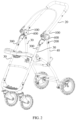
FIG. 1 is a perspective schematic view of a movable carrier according to an embodiment of the present application, wherein the movable carrier is in a locked and fixed state. -
FIG. 2 is a perspective schematic view of a movable carrier according to an embodiment of the present application, wherein the movable carrier is in an unlocked and rotatable state. -
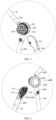
FIG. 3 is a cross-sectional view taken along a line A-A ofFIG. 1 . -
FIG. 4 is a partial exploded view of the movable carrier ofFIG. 1 from a perspective. -
FIG. 5 is a partial exploded view of the movable carrier ofFIG. 1 from another perspective. -
FIG. 6 is a partial exploded view of the movable carrier ofFIG. 1 from yet another perspective. -
FIG. 7 is a perspective schematic view of a first rod of the movable carrier ofFIG. 1 . - 100, first rod; 101, first mating portion; 110, first position; 120, second position; 130, third position; 140, first rotating sector; 141, arc-shaped guiding groove; 150, engaging groove; 151, first groove wall; 152, second groove wall; 200, third rod; 300, second rod; 301, second mating portion; 310, second rotating sector; 311, arc-shaped guiding rib; 312, stopper; 320, engaging protrusion; 400, locking mechanism; 410, first locking shell; 411, first locking groove; 420, elastic member; 430, locking member; 431, locking teeth; 440, second locking shell; 441, through hole; 442, second locking groove; 450, releasing member; 451, pushing portion; 20, handle; 30, front support; 40, rear support.
- As shown in
FIGS. 1 to 2 , an embodiment of the present application provides a foldable and movable carrier. The foldable and movable carrier includes afirst rod 100, athird rod 200, and asecond rod 300. In this embodiment, the carrier may be a stroller. The stroller includes ahandle 20, afront support 30, and arear support 40. In this embodiment, thefirst rod 100, thethird rod 200, and thesecond rod 300 are all hollow rods, and are respectively sleeved on an end of thehandle 20, an end of therear support 40, and an end of thefront support 30. Certainly, in other embodiments, thefirst rod 100, thethird rod 200, and thesecond rod 300 may also be connected to thehandle 20, therear support 40, and thefront support 30 by other means, respectively. Or, thefirst rod 100, thethird rod 200, and thesecond rod 300 are formed as a part of thehandle 20, a part of therear support 40, and a part of thefront support 30, respectively. In a word, the present application can be achieved as long as movements of thefirst rod 100, thethird rod 200, and thesecond rod 300 can drive thehandle 20, thefront support 30, and therear support 40 to move accordingly. The foldable andmovable carrier 10 can prevent thehandle 20 of the stroller from pivoting after alocking mechanism 400 is unintentionally released, so that the stroller can be relocked, and the safety performance of the stroller can be improved. - Specifically, as shown in
FIGS. 2 and7 , thefirst rod 100 includes afirst position 110, asecond position 120, and athird position 130 which are sequentially spaced apart in an extending direction of thefirst rod 100. It should be noted that the structure of the movable carrier of the present application is not limited to herein. In this embodiment, thefirst rod 100 is sleeved on a bottom end of thehandle 20. Certainly, thefirst rod 100 can also be connected to the bottom end of thehandle 20 or be formed as a part of the bottom end of thehandle 20. Afirst mating portion 101 is disposed in thethird position 130. - The
third rod 200 is pivotally connected to thefirst rod 100 in thefirst position 110 through thelocking mechanism 400. Thelocking mechanism 400 has a locked state and an unlocked state. When thelocking mechanism 400 is in the locked state, thefirst rod 100 and thethird rod 200 are relatively fixed and arranged at a first preset included angle. When thelocking mechanism 400 is in the unlocked state, thefirst rod 100 can rotate relative to thethird rod 200. In this embodiment, thethird rod 200 is sleeved on a top end of therear support 40. Certainly, thethird rod 200 can also be connected to the top end of therear support 40 or be formed as a part of the top end of therear support 40 by other means. In this embodiment, the first preset included angle is an acute angle. - In this embodiment, as shown in
FIGS. 4 to 6 , thelocking mechanism 400 includes afirst locking shell 410, anelastic member 420, a lockingmember 430, asecond locking shell 440, and a releasingmember 450, which are arranged in sequence. Thefirst locking shell 410 is fixed on thefirst rod 100 or is a part of thefirst rod 100. Thefirst locking shell 410 includes afirst locking groove 411. Thesecond locking shell 440 is fixed on thethird rod 200, or is formed as a part of thethird rod 200. Thesecond locking shell 440 includes asecond locking groove 442. The lockingmember 430 includes at least two lockingteeth 431 arranged at a predetermined angle. Shapes of thefirst locking groove 411 and thesecond locking groove 442 are both adapted to a shape of the lockingmember 430. In this embodiment, the lockingmember 430 is a gear-shapedlocking member 430. Thefirst locking groove 411 and thesecond locking groove 442 are both gear-shaped locking grooves mating with the gear-shapedlocking member 430. The lockingmember 430 has a locked state and an unlocked state. When the lockingmember 430 is in the locked state, the lockingmember 430 is arranged in both thefirst locking shell 410 and thesecond locking shell 440 to limit the rotation of thesecond locking shell 440 relative to thefirst locking shell 410. When the lockingmember 430 is in the unlocked state, the lockingmember 430 is withdrawn from thefirst locking groove 411 or thesecond locking groove 442 to allow thesecond locking shell 440 to rotate relative to thefirst locking shell 410. Theelastic member 420 is operably connected to the lockingmember 430, for maintaining the lockingmember 430 in the locked state. In this embodiment, theelastic member 420 is a spring. Two ends of the spring abut against thefirst locking shell 410 and the lockingmember 430, respectively. The releasingmember 450 is operably connected to the lockingmember 430, for driving the lockingmember 430 to move against the elastic force of theelastic member 420 to switch the lockingmember 430 from the locked state to the unlocked state. In this embodiment, the releasingmember 450 is a release button. The release button is provided with a pushingportion 451. Thesecond locking shell 440 is provided with a throughhole 441 through which the pushingportion 451 can pass. - In this way, when the releasing
member 450 is not pressed, and when the lockingmember 430 is in the locked state, the lockingmember 430 is locked into both thefirst locking shell 410 and thesecond locking shell 440 under the elastic force of theelastic member 420 that is a return spring. In this case, thefirst locking shell 410 and thesecond locking shell 440 are in the locked state, that is, thefirst rod 100 and thethird rod 200 are in the locked state. When the releasingmember 450 is pressed, the pushingportion 451 can pass through the throughhole 441 to press thesecond locking shell 440 and the lockingmember 430, so that the lockingmember 430 is separated from thefirst locking groove 411 or thesecond locking groove 442. In this case, thefirst locking shell 410 and thesecond locking shell 440 are in the released state, that is, thefirst rod 100 can rotate relative to thethird rod 200. Thelocking mechanism 400 has a simple structure and can enable thefirst rod 100 and thethird rod 200 to switch between the locked state and the unlocked state. However, when the releasingmember 450 is unintentionally pressed, thefirst rod 100 will pivot under the action of external force or its own gravity, so that the lockingteeth 431 of the lockingmember 430 are misaligned with thefirst locking groove 411 or thesecond locking groove 442, so that it is difficult for the lockingmember 430 to reengage into thefirst locking groove 411 or thesecond locking groove 442 such that thefirst locking shell 410 and thesecond locking shell 440 are in the locked state again. That is, it is difficult to bring thefirst rod 100 and thethird rod 200 into a relatively locked and fixed state again. - The
second rod 300 is pivotally connected to thefirst rod 100 in thesecond position 120. Thesecond rod 300 is provided with asecond mating portion 301 detachably mating with thefirst mating portion 101. When thefirst mating portion 101 mates with thesecond mating portion 301, thefirst rod 100 and thesecond rod 300 are relatively fixed and arranged at a second preset included angle. When thefirst mating portion 101 and thesecond mating portion 301 are released from mating, thefirst rod 100 can rotate relative to thesecond rod 300, and an included angle facing thethird rod 200, between thefirst rod 100 and thesecond rod 300 is less than or equal to the second preset included angle. In this embodiment, the second preset included angle is 180 degrees. In this way, when thefirst mating portion 101 mates with thesecond mating portion 301, thefirst rod 100 and thesecond rod 300 are on the same straight line. In addition, since the first preset included angle is an acute angle, when thelocking mechanism 400 is in the locked and fixed state, a combined structure of thefirst rod 100 and thesecond rod 300, and thethird rod 200 form a triangular support structure. Furthermore, because the included angle facing thethird rod 200, between thefirst rod 100 and thesecond rod 300 is always kept less than or equal to the second preset included angle, that is, when thelocking mechanism 400 is in the locked state, thefirst rod 100 can neither rotate from thethird rod 200 to thesecond rod 300 nor from thesecond rod 300 to thethird rod 200. Therefore, when thelocking mechanism 400 is in the locked state, thefirst rod 100 and thesecond rod 300 can be kept at the first preset included angle, thereby providing a stable triangular support structure for the whole stroller. - In this way, when the
locking mechanism 400 is in the locked state, thefirst rod 100, thesecond rod 300, and thethird rod 200 form a stable triangular support structure, so that thefirst rod 100 and thesecond rod 300 are relatively fixed, and thefirst rod 100 and thethird rod 200 are also relatively fixed. When thelocking mechanism 400 is unintentionally pressed and unlocked, since thefirst mating portion 101 which mates with thesecond mating portion 301 of thesecond rod 300 is disposed in thethird position 130 of thefirst rod 100, thefirst mating portion 101 mates with thesecond mating portion 301, thefirst rod 100 and thesecond rod 300 are still relatively fixed, and thefirst rod 100 will not pivot. In this way, thefirst rod 100 can be prevented from pivoting in a state of unintentional release such that thelocking mechanism 400 cannot be restored to the locked state, and thefirst rod 100 and thesecond rod 300 cannot be locked and fixed. When the foldable andmovable carrier 10 needs to be folded, thelocking mechanism 400 is unlocked, and a certain external force is applied to thefirst rod 100 at the same time, so that thefirst mating portion 101 and thesecond mating portion 301 are released from mating. In this way, the relative fixed state among thefirst rod 100, thethird rod 200, and thesecond rod 300 can be released, and the foldable andmovable carrier 10 can be folded. - In an embodiment, as shown in
FIGS. 4 to 7 , a bottom end of thefirst rod 100 is provided with a firstrotating sector 140, a top end of thesecond rod 300 is provided with a secondrotating sector 310. Thesecond position 120 is disposed at a circle center of the firstrotating sector 140. A circle center of the secondrotating sector 310 is pivotally connected to the firstrotating sector 140 in the second position 120 (i.e., the circle center of the first rotating sector 140). A surface of the firstrotating sector 140 facing the secondrotating sector 310 is provided with at least two arc-shaped guidinggrooves 141 that are concentric with the firstrotating sector 140. A surface of the secondrotating sector 310 facing the firstrotating sector 140 is provided with at least two arc-shaped guidingribs 311 that are concentric with the secondrotating sector 310. The arc-shaped guidingribs 311 mates with the arc-shaped guidinggrooves 141 in one-to-one correspondence, to guide the rotations of thefirst rod 100 and thesecond rod 300, to facilitate the folding of the movable carrier. It can be understood that the locations of the arc-shaped guidinggrooves 141 and the locations of the arc-shaped guidingribs 311 can be interchanged. - In an embodiment, as shown in
FIGS. 6 and7 , thefirst mating portion 101 is disposed at a circumferential edge of the surface of the firstrotating sector 140 facing the secondrotating sector 310, and thesecond mating portion 301 is disposed at a circumferential edge of the surface of the secondrotating sector 310 facing the firstrotating sector 140. In this way, a distance from thesecond position 120 to thethird position 130 is relatively large. According to the lever principle, when the movable carrier is folded, the external force required to be applied to release the mating between thefirst mating portion 101 and thesecond mating portion 301 is smaller, which means that less effort is required when the movable carrier is folded. Certainly, the locations of thefirst mating portion 101 and thesecond mating portion 301 can also be arranged according to actual needs. For example, thefirst mating portion 101 and thesecond mating portion 301 can be arranged closer to the circle center of the firstrotating sector 140 and the circle center of the secondrotating sector 310, respectively, so that when thelocking mechanism 400 is unintentionally released, thefirst rod 100 is more difficult to pivot, etc., which is not limited to herein. - Further, a
stopper 312 is disposed on a side of the secondrotating sector 310 close to thethird rod 200. When thefirst rod 100 and thesecond rod 300 are arranged at the second preset included angle, the firstrotating sector 140 abuts against thestopper 312. Thestopper 312 may be a stopping protrusion, a stopping slope, or the like. In this embodiment, thestopper 312 is a stopping slope disposed at the circumferential edge of the surface of the secondrotating sector 310 facing the firstrotating sector 140, and the stopping slope is gradually raised in a direction of approaching thethird rod 200. In this way, it can be ensured that the included angle facing thethird rod 200, between thefirst rod 100 and thesecond rod 300 is always less than or equal to the second preset included angle. - Optionally, the
first mating portion 101 is a male connecting portion, and thesecond mating portion 301 is a female connecting portion that can detachably mate with the male connecting portion. Or, thefirst mating portion 101 is a female connecting portion, and thesecond mating portion 301 is a male connecting portion that can detachably mate with the female connecting portion. - In an embodiment, as shown in
FIGS. 6 and7 , thefirst mating portion 101 is anengaging groove 150, and thesecond mating portion 301 is anengaging protrusion 320 capable of being engaged with the engaginggroove 150. In this way, when thelocking mechanism 400 is unintentionally unlocked, since the engagingprotrusion 320 of thesecond rod 300 is engaged into the engaginggroove 150 of thefirst rod 100, thefirst rod 100 is not easy to pivot under the action of external force or its own gravity, so that thelocking mechanism 400 can be restored to the locked state again, and thus the movable carrier can be relocked and refixed. When the movable carrier needs to be folded, it is only necessary to apply a certain external force on thefirst rod 100 to make the engagingprotrusion 320 rotate out from the engaginggroove 150, which ensures the foldable function of the movable carrier. It can be understood that thefirst mating portion 101 can also be the engagingprotrusion 320, and thesecond mating portion 301 can be the engaginggroove 150 capable of being engaged with the engagingprotrusion 320. - In this embodiment, the engaging
groove 150 is disposed on the circumferential edge of the surface of the firstrotating sector 140 facing the secondrotating sector 310, and the engagingprotrusion 320 is disposed on the circumferential edge of the surface of the secondrotating sector 310 facing the firstrotating sector 140. Certainly, in other embodiments, the engaginggroove 150 may also be disposed in other positions of the firstrotating sector 140, and the engagingprotrusion 320 may also be disposed in other positions of the secondrotating sector 310. - Further, as shown in
FIG. 3 , the engaginggroove 150 is a V-shaped groove. The V-shaped groove includes afirst groove wall 151 and asecond groove wall 152 that are arranged in a V shape. The engagingprotrusion 320 is an arc-shaped protrusion capable of being tangent to the groove walls of the V-shaped groove. That is, a cross-sectional shape of the engaginggroove 150 perpendicular to thefirst rod 100 is V-shaped, and a cross-sectional shape of the engagingprotrusion 320 perpendicular to thethird rod 200 is arc-shaped. In this way, when thefirst rod 100 rotates to be engaged and fixed to thethird rod 200, the engagingprotrusion 320 can be more smoothly engaged into the engaginggroove 150. When the fixing between thefirst rod 100 and thethird rod 200 is released, the engagingprotrusion 320 can also be easily rotated out from the engaginggroove 150. Optionally, a first included angle between thefirst groove wall 151 and a plane where an opening of the V-shaped groove is located is in a range from 40° to 50°. In this embodiment, the first included angle is 45°. A second included angle between thesecond groove wall 152 and the plane where the opening of the V-shaped groove is located is in a range from 40° to 50°. In this embodiment, the second included angle is 45°. A height of the arc-shaped protrusion is in a range from 1.5mm to 2.5mm. In this embodiment, the height is 2mm. The above configuration can prevent the realization of the foldable function of the movable carrier from being affected even when thelocking mechanism 400 is unintentionally released while thefirst rod 100 is pivoting. - Further, the engaging
protrusion 320 is a serrated protrusion including at least two engaging teeth, and the engaginggroove 150 is a serrated groove including at least two engaging grooves. The at least two engaging teeth can mate with the at least two engaging grooves one by one. Compared with the mating between the single protrusion and the groove, the mating structure of the serrated protrusion and the serrated groove can provide a larger friction force, so that thefirst rod 100 has a stronger anti-pivoting ability during the unintentional release. Certainly, under the condition of the same required anti-pivoting ability, the height of the serrated protrusion can be less than that of the single protrusion, and the depth of the corresponding engaginggroove 150 can also be less than that of the single groove. - In another embodiment, the
first mating portion 101 may be a plug hole, and thesecond mating portion 301 may be a plug pin capable of being plugged into the plug hole. In this way, when thelocking mechanism 400 is unintentionally unlocked, since the plug pin of thefirst rod 100 is plugged into the plug hole of thesecond rod 300, thefirst rod 100 is not easy to pivot under the action of external force or its own gravity, so that it is convenient to restore thelocking mechanism 400 to the locked state again, and thus the foldable andmovable carrier 10 can be relocked and refixed. When the movable carrier needs to be folded, it is only necessary to apply a certain external force to thefirst rod 100 to make the plug pin rotate out from the plug hole, which ensures the foldable function of the foldable and movable carrier. It can be understood that thefirst mating portion 101 can also be a plug pin, and thesecond mating portion 301 can also be a plug hole capable of being plugged with the plug pin. - Further, a hole wall of the plug hole can be elastically deformed. When the hole wall of the plug hole is elastically deformed, an inner diameter of the plug hole is greater than a diameter of the plug pin. When the hole wall of the plug hole is restored to its original shape, the inner diameter of the plug hole is less than the diameter of the plug pin. Or, the plug pin can be elastically deformed. When the plug pin is elastically deformed, the diameter of the plug pin is less than the inner diameter of the plug hole; and when the plug pin is restored to its original state, the diameter of the plug pin is greater than the inner diameter of the plug hole. On the one hand, this configuration facilitates the plug pin plugging into the plug hole, and keeping the plug pin stably in the plug hole without easily coming out of the plug hole; and on the other hand, this configuration is also convenient for the plug pin to come out from the plug hole when external force is applied.
- Optionally, both the
first rod 100 and thesecond rod 300 are made of deformable plastic materials, so as to facilitate the mating and separation of thefirst mating portion 101 and thesecond mating portion 301. - The above-mentioned foldable and
movable carrier 10 at least have the following technical effects. - When the
locking mechanism 400 is unintentionally unlocked, since thefirst mating portion 101 and thesecond mating portion 301 are in a mating state, thefirst rod 100 pivotally connected to thesecond rod 300 is not easy to pivot, so that the user can reset thelocking mechanism 400, and thus the movable carrier can be restored to the locked and fixed state, and as a result, the safety of the entire movable carrier can be improved. In addition, when it is really necessary to release the locking, thelocking mechanism 400 can be pressed, and thefirst mating portion 101 and thesecond mating portion 301 can be released from the mating, for example, by applying a certain external force, so that thefirst rod 100 can rotate and be folded relative to thesecond rod 300, to ensure the realization of the foldable function of the movable carrier. - The technical features of the above-described embodiments can be combined arbitrarily. To simplify the description, not all possible combinations of the technical features in the above embodiments are described. However, all of the combinations of these technical features should be considered as being fallen within the scope of the present application, as long as such combinations do not contradict with each other.
- The foregoing embodiments merely illustrate some embodiments of the present application, and descriptions thereof are relatively specific and detailed. However, it should not be understood as a limitation to the patent scope of the present application. It should be noted that, a person of ordinary skill in the art may further make some variations and improvements without departing from the concept of the present application, and the variations and improvements falls in the protection scope of the present application. Therefore, the protection scope of the present application shall be subject to the appended claims.
- The subject-matter of the present invention relates, inter alia, to the following aspects:
- 1. A foldable and movable carrier (10), comprising:
- a locking mechanism (400) having a locked state and an unlocked state;
- a first rod (100) provided with a first mating portion (101); and
- a second rod (300) pivotally connected to the first rod (100), and the second rod (300) being provided with a second mating portion (301) detachably mating with the first mating portion (101);
- wherein when the locking mechanism (400) is in the locked state, the first rod (100) and the second rod (300) are relatively fixed; when the locking mechanism (400) is in the unlocked state, if the first mating portion (101) mates with the second mating portion (301), the first rod (100) and the second rod (300) are relatively fixed, if the first mating portion (101) and the second mating portion (301) are released from mating, the first rod (100) is capable of rotating relative to the second rod (300), so as to fold or unfold the movable carrier (10).
- 2. The foldable and movable carrier (10) according to
aspect 1, wherein the first mating portion (101) is a male connecting portion, and the second mating portion (301) is a female connecting portion capable of detachably mating with the male connecting portion; or, the first mating portion (101) is a female connecting portion, and the second mating portion (301) is a male connecting portion capable of detachably mating with the female connecting portion. - 3. The foldable and movable carrier (10) according to any one of
aspects 1 or 2, wherein one of the first mating portion (101) and the second mating portion (301) is an engaging groove (150); another one of the first mating portion (101) and the second mating portion (301) is an engaging protrusion (320) capable of being engaged with the engaging groove (150). - 4. The foldable and movable carrier (10) according to aspect 3, wherein the engaging groove (150) is a V-shaped groove; the V-shaped groove comprises a first groove wall (151) and a second groove wall (152) that are arranged in a V shape; and the engaging protrusion (320) is an arc-shaped protrusion capable of being tangent to the first groove wall (151) and the second groove wall (152).
- 5. The foldable and movable carrier (10) according to aspect 4, wherein an included angle between the first groove wall (151) and a plane where an opening of the V-shaped groove is located is in a range from 40° to 50°; an included angle between the second groove wall (152) and the plane where the opening of the V-shaped groove is located is in a range from 40° to 50°; and a height of the arc-shaped protrusion is in a range from 1.5mm to 2.5mm.
- 6. The foldable and movable carrier (10) according to any one of aspects 3 to 5, wherein the engaging protrusion (320) is a serrated protrusion comprising at least two engaging teeth; the engaging groove (150) is a serrated groove comprising at least two engaging grooves; and the at least two engaging teeth are capable of mating with the at least two engaging grooves one by one.
- 7. The foldable and movable carrier (10) according to aspect 2, whereinhe one of the first mating portion (101) and the second mating portion (301) is a plug hole; and another one of the first mating portion (101) and the second mating portion (301) is a plug pin capable of being plugged into the plug hole.
- 8. The foldable and movable carrier (10) according to aspect 7, wherein a hole wall of the plug hole is capable of being elastically deformed; when the hole wall of the plug hole is elastically deformed, an inner diameter of the plug hole is greater than a diameter of the plug pin; when the hole wall of the plug hole is restored to its original shape, the inner diameter of the plug hole is less than the diameter of the plug pin; or
the plug pin is capable of being elastically deformed; when the plug pin is elastically deformed, a diameter of the plug pin is less than an inner diameter of the plug hole; and when the plug pin is restored to its original state, the diameter of the plug pin is greater than the inner diameter of the plug hole. - 9. The foldable and movable carrier (10) according to any one of
aspects 1 to 8, further comprising a third rod (200); and wherein the first rod (100) comprises a first position (110), a second position (120), and a third position (130) that are sequentially spaced apart in an extending direction of the first rod (100); the first mating portion (101) is disposed in the third position (130); the third rod (200) is pivotally connected to the first rod (100) in the first position (110) through the locking mechanism (400); when the locking mechanism (400) is in the locked state, the first rod (100) and the third rod (200) are relatively fixed; when the locking mechanism (400) is in the unlocked state, the first rod (100) is capable of rotating relative to the third rod (200), so as to fold or unfold the movable carrier (10); and the second rod (300) is pivotally connected to the first rod (100) in the second position (120). - 10. The foldable and movable carrier (10) according to aspect 9, wherein an end of the first rod (100) is provided with a first rotating sector (140), an end of the second rod (300) is provided with a second rotating sector (310); the first rotating sector (140) is opposite to the second rotating sector (310); the second position (120) is disposed at a circle center of the first rotating sector (140); a circle center of the second rotating sector (310) is pivotally connected to the first rotating sector (140) in the second position (120); the first mating portion (101) is disposed at a circumferential edge of a surface of the first rotating sector (140) facing the second rotating sector (310); the second mating portion (301) is disposed at a circumferential edge of a surface of the second rotating sector (310) facing the first rotating sector (140).
- 11. The foldable and movable carrier (10) according to
aspect 10, wherein a stopper (312) is disposed on a side of the second rotating sector (310) close to the third rod (200); when the first rod (100) and the second rod (300) are arranged at a second preset included angle, the first rotating sector (140) abuts against the stopper (312). - 12. The foldable and movable carrier (10) according to any one of aspects 9 to 11, wherein the locking mechanism (400) comprises:
- a first locking shell (410) fixed on the first rod (100) and comprising a first locking groove (411);
- a second locking shell (440) fixed on the third rod (200) and comprising a second locking groove (442);
- a locking member (430) comprising at least two locking teeth (431) arranged at a predetermined angle, and wherein shapes of the first locking groove (411) and the second locking groove (442) are adapted to a shape of the locking member (430), the locking member (430) has a locked state and an unlocked state; when the locking member (430) is in the locked state, the locking member (430) is arranged in both the first locking shell (410) and the second locking shell (440) to limit a rotation of the second locking shell (440) relative to the first locking shell (410); when the locking member (430) is in the unlocked state, the locking member (430) is withdrawn from the first locking groove (411) or the second locking groove (442) to allow the second locking shell (440) to rotate relative to the first locking shell (410);
- an elastic member (420) operably connected to the locking member (430), so as to maintain the locking member (430) in the locked state; and
- a releasing member (450) operably connected to the locking member (430), so as to drive the locking member (430) to move against elastic force of the elastic member (420) to switch the locking member (430) from the locked state to the unlocked state.
Claims (15)
- A foldable and movable carrier (10), comprising:a locking mechanism (400) having a locked state and an unlocked state;a first rod (100) provided with a first mating portion (101); anda second rod (300) pivotally connected to the first rod (100), and the second rod (300) being provided with a second mating portion (301) detachably mating with the first mating portion (101);characterized in that, the foldable and movable carrier (10) further comprises a third rod (200) pivotally connected to the first rod (100) through the locking mechanism (400),wherein when the locking mechanism (400) is in the locked state, the first mating portion (101) mates with the second mating portion (301); the first rod (100), the second rod (300) , and the third rod (200) are relatively fixed; when the locking mechanism (400) is in the unlocked state, if the first mating portion (101) mates with the second mating portion (301), the first rod (100) and the second rod (300) are relatively fixed and the locking mechanism (400) is capable of being switched from the unlocked state to the locked state, if the first mating portion (101) and the second mating portion (301) are released from mating, the first rod (100), the second rod (300) and the third rod (200) are capable of rotating relative to each other, so as to fold or unfold the movable carrier (10).
- The foldable and movable carrier (10) according to claim 1, wherein the first mating portion (101) is a male connecting portion, and the second mating portion (301) is a female connecting portion capable of detachably mating with the male connecting portion; or, the first mating portion (101) is a female connecting portion, and the second mating portion (301) is a male connecting portion capable of detachably mating with the female connecting portion.
- The foldable and movable carrier (10) according to any one of claims 1 or 2, wherein one of the first mating portion (101) and the second mating portion (301) is an engaging groove (150); another one of the first mating portion (101) and the second mating portion (301) is an engaging protrusion (320) capable of being engaged with the engaging groove (150); or
wherein one of the first mating portion (101) and the second mating portion (301) is a plug hole; and another one of the first mating portion (101) and the second mating portion (301) is a plug pin capable of being plugged into the plug hole. - The foldable and movable carrier (10) according to claim 1 or 2, wherein one of the first mating portion (101) and the second mating portion (301) is an engaging groove (150); another one of the first mating portion (101) and the second mating portion (301) is an engaging protrusion (320) capable of being engaged with the engaging groove (150); the engaging groove (150) is a V-shaped groove; the V-shaped groove comprises a first groove wall (151) and a second groove wall (152) that are arranged in a V shape; and the engaging protrusion (320) is an arc-shaped protrusion capable of being tangent to the first groove wall (151) and the second groove wall (152).
- The foldable and movable carrier (10) according to claim 4, wherein an included angle between the first groove wall (151) and a plane where an opening of the V-shaped groove is located is in a range from 40° to 50°; an included angle between the second groove wall (152) and the plane where the opening of the V-shaped groove is located is in a range from 40° to 50°; and a height of the arc-shaped protrusion is in a range from 1.5mm to 2.5mm.
- The foldable and movable carrier (10) according to any one of claims 3 to 5, wherein the engaging protrusion (320) is a serrated protrusion comprising at least two engaging teeth; the engaging groove (150) is a serrated groove comprising at least two engaging grooves; and the at least two engaging teeth are capable of mating with the at least two engaging grooves one by one.
- The foldable and movable carrier (10) according to claim 1 or 2, whereinhe one of the first mating portion (101) and the second mating portion (301) is a plug hole; and another one of the first mating portion (101) and the second mating portion (301) is a plug pin capable of being plugged into the plug hole;wherein a hole wall of the plug hole is capable of being elastically deformed; when the hole wall of the plug hole is elastically deformed, an inner diameter of the plug hole is greater than a diameter of the plug pin; when the hole wall of the plug hole is restored to its original shape, the inner diameter of the plug hole is less than the diameter of the plug pin; orthe plug pin is capable of being elastically deformed; when the plug pin is elastically deformed, a diameter of the plug pin is less than an inner diameter of the plug hole; and when the plug pin is restored to its original state, the diameter of the plug pin is greater than the inner diameter of the plug hole.
- The foldable and movable carrier (10) according to any one of claims 1 to 7, wherein the first rod (100) comprises a first position (110), a second position (120), and a third position (130) that are sequentially spaced apart in an extending direction of the first rod (100); the first mating portion (101) is disposed in the third position (130); the third rod (200) is pivotally connected to the first rod (100) in the first position (110) through the locking mechanism (400); and the second rod (300) is pivotally connected to the first rod (100) in the second position (120).
- The foldable and movable carrier (10) according to claim 8, wherein an end of the first rod (100) is provided with a first rotating sector (140), an end of the second rod (300) is provided with a second rotating sector (310); the first rotating sector (140) is opposite to the second rotating sector (310); the second position (120) is disposed at a circle center of the first rotating sector (140); a circle center of the second rotating sector (310) is pivotally connected to the first rotating sector (140) in the second position (120); the first mating portion (101) is disposed at a circumferential edge of a surface of the first rotating sector (140) facing the second rotating sector (310); the second mating portion (301) is disposed at a circumferential edge of a surface of the second rotating sector (310) facing the first rotating sector (140).
- The foldable and movable carrier (10) according to claim 9, wherein a stopper (312) is disposed on a side of the second rotating sector (310) close to the third rod (200); when the first rod (100) and the second rod (300) are arranged at a second angle, the first rotating sector (140) abuts against the stopper (312).
- The foldable and movable carrier (10) according to any one of claims 8 to 10, wherein the locking mechanism (400) comprises:a first locking shell (410) fixed on the first rod (100) and comprising a first locking groove (411);a second locking shell (440) fixed on the third rod (200) and comprising a second locking groove (442);a locking member (430) comprising at least two locking teeth (431) arranged at a predetermined angle, and wherein shapes of the first locking groove (411) and the second locking groove (442) are adapted to a shape of the locking member (430), the locking member (430) has a locked state and an unlocked state; when the locking member (430) is in the locked state, the locking member (430) is arranged in both the first locking shell (410) and the second locking shell (440) to limit a rotation of the second locking shell (440) relative to the first locking shell (410); when the locking member (430) is in the unlocked state, the locking member (430) is withdrawn from the first locking groove (411) or the second locking groove (442) to allow the second locking shell (440) to rotate relative to the first locking shell (410);an elastic member (420) operably connected to the locking member (430), so as to maintain the locking member (430) in the locked state; anda releasing member (450) operably connected to the locking member (430), so as to drive the locking member (430) to move against elastic force of the elastic member (420) to switch the locking member (430) from the locked state to the unlocked state.
- The foldable and movable carrier (10) according to claim 8, wherein an end of the first rod (100) is provided with a first rotating sector (140), an end of the second rod (300) is provided with a second rotating sector (310); the first rotating sector (140) is opposite to the second rotating sector (310);the second position (120) is disposed at a circle center of the first rotating sector (140); a circle center of the second rotating sector (310) is pivotally connected to the first rotating sector (140) in the second position (120);the first mating portion (101) is disposed on a surface of the first rotating sector (140) facing the second rotating sector (310), and disposed closer to the circle center of the first rotating sector (140) than a circumferential edge of the first rotating sector (140);the second mating portion (301) is disposed on a surface of the second rotating sector (310) facing the first rotating sector (140), and disposed closer to the circle center of the second rotating sector (310) than a circumferential edge of the second rotating sector (310).
- The foldable and movable carrier (10) according to claim 9, wherein one of the surface of the first rotating sector (140) facing the second rotating sector (310) and the surface of the second rotating sector (310) facing the first rotating sector (140) is provided with an arc-shaped guiding groove (141); another of the surface of the first rotating sector (140) facing the second rotating sector (310) and the surface of the second rotating sector (310) facing the first rotating sector (140) is provided with an arc-shaped guiding rib (311);
the arc-shaped guiding rib (311) mates with the arc-shaped guiding groove (141) in one-to-one correspondence, to guide rotations of the first rod (100) and the second rod (300). - The foldable and movable carrier (10) according to claim 1, wherein the foldable and movable carrier (10) is a stroller, the stroller further includes a handle (20), a front support (30), and a rear support (40),the first rod (100), the third rod (200), and the second rod (300) are connected to the handle (20), the rear support (40), and the front support (30), respectively, orthe first rod (100), the third rod (200), and the second rod (300) are formed as a part of the handle (20), a part of the rear support (40), and a part of the front support (30), respectively.
- The foldable and movable carrier (10) according to claim 1, wherein when the locking mechanism (400) is in the locked state, the first rod (100) and the third rod (200) are arranged at a first preset included angle, the first rod (100) and the second rod (300) are arranged at a second preset included angle, the second preset included angle is larger than the first preset included angle, when the first mating portion (101) and the second mating portion (301) are released from mating, an included angle between the first rod (100) and the second rod (300) is less than or equal to the second preset included angle.
Applications Claiming Priority (3)
| Application Number | Priority Date | Filing Date | Title |
|---|---|---|---|
| CN202110915281.3A CN115892173B (en) | 2021-08-10 | 2021-08-10 | Foldable mobile vehicle |
| PCT/EP2022/072436 WO2023017076A1 (en) | 2021-08-10 | 2022-08-10 | Foldable and movable carrier |
| EP22764708.8A EP4384430B1 (en) | 2021-08-10 | 2022-08-10 | Foldable and movable carrier |
Related Parent Applications (2)
| Application Number | Title | Priority Date | Filing Date |
|---|---|---|---|
| EP22764708.8A Division EP4384430B1 (en) | 2021-08-10 | 2022-08-10 | Foldable and movable carrier |
| EP22764708.8A Division-Into EP4384430B1 (en) | 2021-08-10 | 2022-08-10 | Foldable and movable carrier |
Publications (2)
| Publication Number | Publication Date |
|---|---|
| EP4574626A2 true EP4574626A2 (en) | 2025-06-25 |
| EP4574626A3 EP4574626A3 (en) | 2025-09-24 |
Family
ID=83192078
Family Applications (2)
| Application Number | Title | Priority Date | Filing Date |
|---|---|---|---|
| EP22764708.8A Active EP4384430B1 (en) | 2021-08-10 | 2022-08-10 | Foldable and movable carrier |
| EP25176089.8A Pending EP4574626A3 (en) | 2021-08-10 | 2022-08-10 | Foldable and movable carrier |
Family Applications Before (1)
| Application Number | Title | Priority Date | Filing Date |
|---|---|---|---|
| EP22764708.8A Active EP4384430B1 (en) | 2021-08-10 | 2022-08-10 | Foldable and movable carrier |
Country Status (9)
| Country | Link |
|---|---|
| US (1) | US20240375699A1 (en) |
| EP (2) | EP4384430B1 (en) |
| JP (2) | JP7673322B2 (en) |
| CN (2) | CN121990032A (en) |
| AU (2) | AU2022325475B2 (en) |
| DE (1) | DE112022003893T5 (en) |
| ES (1) | ES3037406T3 (en) |
| TW (1) | TWI833322B (en) |
| WO (1) | WO2023017076A1 (en) |
Families Citing this family (1)
| Publication number | Priority date | Publication date | Assignee | Title |
|---|---|---|---|---|
| CN115246434A (en) * | 2021-04-28 | 2022-10-28 | 明门瑞士股份有限公司 | Frame and Stroller |
Family Cites Families (16)
| Publication number | Priority date | Publication date | Assignee | Title |
|---|---|---|---|---|
| TWM250041U (en) * | 2004-01-12 | 2004-11-11 | Bo-Li Wang | Heat dissipation device for oil pan of automobile engine |
| TW200911594A (en) * | 2007-01-16 | 2009-03-16 | Combi Corp | Baby carriage |
| GB2500051B (en) * | 2012-03-08 | 2018-02-07 | Mamas & Papas (Holdings) Ltd | Child support apparatus |
| CN103419827B (en) * | 2012-05-18 | 2016-01-13 | 明门香港股份有限公司 | Secondary locking mechanism and foldable frame |
| CN103832457B (en) * | 2012-11-27 | 2016-04-27 | 明门香港股份有限公司 | Armrest folding device for pushchair |
| CN106143575B (en) * | 2015-04-23 | 2019-01-22 | 明门香港股份有限公司 | Folding baby carriage |
| DE102015115396A1 (en) * | 2015-09-11 | 2017-03-16 | Bumbleride Inc. | buggy |
| CN206217964U (en) * | 2016-11-21 | 2017-06-06 | 浙江晨辉婴宝儿童用品有限公司 | A kind of folding baby carrier for improving linkage |
| CN207089389U (en) * | 2017-05-22 | 2018-03-13 | 稳正企业股份有限公司 | Hand cart |
| CN107985379B (en) * | 2017-11-29 | 2025-01-21 | 好孩子儿童用品有限公司 | Strollers |
| CN108909813B (en) * | 2018-07-07 | 2023-07-11 | 广东乐美达集团有限公司 | Quick folding baby carriage |
| CN208963151U (en) * | 2018-07-07 | 2019-06-11 | 广东乐美达集团有限公司 | Perambulator with Collapsible seat structure |
| CN208530667U (en) * | 2018-07-25 | 2019-02-22 | 慈溪市福贝贝儿童用品有限公司 | Vehicle frame and perambulator with the vehicle frame |
| CN111409682A (en) * | 2019-01-07 | 2020-07-14 | 明门瑞士股份有限公司 | Frame and Stroller |
| CN110733553B (en) * | 2019-09-20 | 2024-11-29 | 好孩子儿童用品有限公司 | A cart |
| CN215475320U (en) * | 2021-08-10 | 2022-01-11 | 明门(中国)幼童用品有限公司 | Collapsible mobile vehicle |
-
2021
- 2021-08-10 CN CN202610213374.4A patent/CN121990032A/en active Pending
- 2021-08-10 CN CN202110915281.3A patent/CN115892173B/en active Active
-
2022
- 2022-08-10 EP EP22764708.8A patent/EP4384430B1/en active Active
- 2022-08-10 AU AU2022325475A patent/AU2022325475B2/en active Active
- 2022-08-10 EP EP25176089.8A patent/EP4574626A3/en active Pending
- 2022-08-10 TW TW111130018A patent/TWI833322B/en active
- 2022-08-10 US US18/292,473 patent/US20240375699A1/en active Pending
- 2022-08-10 JP JP2024508343A patent/JP7673322B2/en active Active
- 2022-08-10 WO PCT/EP2022/072436 patent/WO2023017076A1/en not_active Ceased
- 2022-08-10 DE DE112022003893.4T patent/DE112022003893T5/en active Pending
- 2022-08-10 ES ES22764708T patent/ES3037406T3/en active Active
-
2025
- 2025-04-23 JP JP2025071808A patent/JP2025111635A/en active Pending
-
2026
- 2026-04-14 AU AU2026202787A patent/AU2026202787A1/en active Pending
Also Published As
| Publication number | Publication date |
|---|---|
| AU2022325475B2 (en) | 2026-01-15 |
| JP2024530675A (en) | 2024-08-23 |
| CN121990032A (en) | 2026-05-08 |
| AU2026202787A1 (en) | 2026-04-30 |
| EP4574626A3 (en) | 2025-09-24 |
| TW202306817A (en) | 2023-02-16 |
| AU2022325475A1 (en) | 2024-03-28 |
| EP4384430B1 (en) | 2025-06-18 |
| JP2025111635A (en) | 2025-07-30 |
| CN115892173A (en) | 2023-04-04 |
| TWI833322B (en) | 2024-02-21 |
| EP4384430A1 (en) | 2024-06-19 |
| US20240375699A1 (en) | 2024-11-14 |
| JP7673322B2 (en) | 2025-05-08 |
| WO2023017076A1 (en) | 2023-02-16 |
| DE112022003893T5 (en) | 2024-05-16 |
| ES3037406T3 (en) | 2025-10-01 |
| CN115892173B (en) | 2026-03-13 |
Similar Documents
| Publication | Publication Date | Title |
|---|---|---|
| AU2026202787A1 (en) | Foldable and movable carrier | |
| CN102642555B (en) | stroller | |
| EP3653476B1 (en) | A kick scooter | |
| US10479389B2 (en) | Collapsible seat assembly and a stroller with the same | |
| EP3119253B1 (en) | Portable toilet device for a small child | |
| EP4049556B1 (en) | Locking mechanism | |
| PT1461259E (en) | Collapsible container comprising a container base and four collapsible lateral walls | |
| JP7728751B2 (en) | Pivot and locking mechanism for step ladders | |
| CN104057994B (en) | Wheel orienting device | |
| EP4253193A2 (en) | Unlock device and stroller | |
| US20220324502A1 (en) | Stroller, stroller frame and folding device thereof | |
| TW202506468A (en) | Child carrying mechanism and related child carrier | |
| JP7170795B2 (en) | Child carrier with storage assembly | |
| CN103315570A (en) | Collapsible mechanism and collapsible rocking chair with the collapsible mechanism | |
| US20250002068A1 (en) | Folding joint and child carrier | |
| CN215475320U (en) | Collapsible mobile vehicle | |
| CN206938832U (en) | Rotating assembly and foldable children's trolley with same | |
| WO2023230852A1 (en) | Locking connecting device and combined container | |
| CN118046951A (en) | Folding device of cart and cart | |
| JP2004284641A (en) | Folding transportation container and transportation container | |
| CN211107638U (en) | Folding joint and baby carriage with same | |
| CN208963151U (en) | Perambulator with Collapsible seat structure | |
| TW202448734A (en) | Frame and stroller | |
| TW202612956A (en) | Carrier and stroller | |
| WO2025209543A1 (en) | Stroller and joint structures thereof |
Legal Events
| Date | Code | Title | Description |
|---|---|---|---|
| PUAI | Public reference made under article 153(3) epc to a published international application that has entered the european phase |
Free format text: ORIGINAL CODE: 0009012 |
|
| STAA | Information on the status of an ep patent application or granted ep patent |
Free format text: STATUS: REQUEST FOR EXAMINATION WAS MADE |
|
| 17P | Request for examination filed |
Effective date: 20250513 |
|
| AC | Divisional application: reference to earlier application |
Ref document number: 4384430 Country of ref document: EP Kind code of ref document: P |
|
| AK | Designated contracting states |
Kind code of ref document: A2 Designated state(s): AL AT BE BG CH CY CZ DE DK EE ES FI FR GB GR HR HU IE IS IT LI LT LU LV MC MK MT NL NO PL PT RO RS SE SI SK SM TR |
|
| REG | Reference to a national code |
Ref country code: DE Ref legal event code: R079 Free format text: PREVIOUS MAIN CLASS: B62B0007080000 Ipc: B62B0007060000 |
|
| PUAL | Search report despatched |
Free format text: ORIGINAL CODE: 0009013 |
|
| AK | Designated contracting states |
Kind code of ref document: A3 Designated state(s): AL AT BE BG CH CY CZ DE DK EE ES FI FR GB GR HR HU IE IS IT LI LT LU LV MC MK MT NL NO PL PT RO RS SE SI SK SM TR |
|
| RIC1 | Information provided on ipc code assigned before grant |
Ipc: B62B 7/06 20060101AFI20250819BHEP Ipc: B62B 7/08 20060101ALI20250819BHEP |