EP4574540A1 - Electric work vehicle - Google Patents
Electric work vehicle Download PDFInfo
- Publication number
- EP4574540A1 EP4574540A1 EP23854667.5A EP23854667A EP4574540A1 EP 4574540 A1 EP4574540 A1 EP 4574540A1 EP 23854667 A EP23854667 A EP 23854667A EP 4574540 A1 EP4574540 A1 EP 4574540A1
- Authority
- EP
- European Patent Office
- Prior art keywords
- charging
- control unit
- battery
- state
- electric motor
- Prior art date
- Legal status (The legal status is an assumption and is not a legal conclusion. Google has not performed a legal analysis and makes no representation as to the accuracy of the status listed.)
- Pending
Links
Images



Classifications
-
- B—PERFORMING OPERATIONS; TRANSPORTING
- B60—VEHICLES IN GENERAL
- B60L—PROPULSION OF ELECTRICALLY-PROPELLED VEHICLES; SUPPLYING ELECTRIC POWER FOR AUXILIARY EQUIPMENT OF ELECTRICALLY-PROPELLED VEHICLES; ELECTRODYNAMIC BRAKE SYSTEMS FOR VEHICLES IN GENERAL; MAGNETIC SUSPENSION OR LEVITATION FOR VEHICLES; MONITORING OPERATING VARIABLES OF ELECTRICALLY-PROPELLED VEHICLES; ELECTRIC SAFETY DEVICES FOR ELECTRICALLY-PROPELLED VEHICLES
- B60L50/00—Electric propulsion with power supplied within the vehicle
- B60L50/50—Electric propulsion with power supplied within the vehicle using propulsion power supplied by batteries or fuel cells
- B60L50/60—Electric propulsion with power supplied within the vehicle using propulsion power supplied by batteries or fuel cells using power supplied by batteries
-
- H—ELECTRICITY
- H02—GENERATION; CONVERSION OR DISTRIBUTION OF ELECTRIC POWER
- H02J—ELECTRIC POWER NETWORKS; CIRCUIT ARRANGEMENTS OR SYSTEMS FOR SUPPLYING OR DISTRIBUTING ELECTRIC POWER; SYSTEMS FOR STORING ELECTRIC ENERGY
- H02J7/00—Circuit arrangements for charging or discharging batteries or for supplying loads from batteries
- H02J7/60—Circuit arrangements for charging or discharging batteries or for supplying loads from batteries including safety or protection arrangements
-
- B—PERFORMING OPERATIONS; TRANSPORTING
- B60—VEHICLES IN GENERAL
- B60L—PROPULSION OF ELECTRICALLY-PROPELLED VEHICLES; SUPPLYING ELECTRIC POWER FOR AUXILIARY EQUIPMENT OF ELECTRICALLY-PROPELLED VEHICLES; ELECTRODYNAMIC BRAKE SYSTEMS FOR VEHICLES IN GENERAL; MAGNETIC SUSPENSION OR LEVITATION FOR VEHICLES; MONITORING OPERATING VARIABLES OF ELECTRICALLY-PROPELLED VEHICLES; ELECTRIC SAFETY DEVICES FOR ELECTRICALLY-PROPELLED VEHICLES
- B60L1/00—Supplying electric power to auxiliary equipment of vehicles
- B60L1/003—Supplying electric power to auxiliary equipment of vehicles to auxiliary motors, e.g. for pumps, compressors
-
- B—PERFORMING OPERATIONS; TRANSPORTING
- B60—VEHICLES IN GENERAL
- B60L—PROPULSION OF ELECTRICALLY-PROPELLED VEHICLES; SUPPLYING ELECTRIC POWER FOR AUXILIARY EQUIPMENT OF ELECTRICALLY-PROPELLED VEHICLES; ELECTRODYNAMIC BRAKE SYSTEMS FOR VEHICLES IN GENERAL; MAGNETIC SUSPENSION OR LEVITATION FOR VEHICLES; MONITORING OPERATING VARIABLES OF ELECTRICALLY-PROPELLED VEHICLES; ELECTRIC SAFETY DEVICES FOR ELECTRICALLY-PROPELLED VEHICLES
- B60L15/00—Methods, circuits, or devices for controlling the traction-motor speed of electrically-propelled vehicles
- B60L15/20—Methods, circuits, or devices for controlling the traction-motor speed of electrically-propelled vehicles for control of the vehicle or its driving motor to achieve a desired performance, e.g. speed, torque, programmed variation of speed
-
- B—PERFORMING OPERATIONS; TRANSPORTING
- B60—VEHICLES IN GENERAL
- B60L—PROPULSION OF ELECTRICALLY-PROPELLED VEHICLES; SUPPLYING ELECTRIC POWER FOR AUXILIARY EQUIPMENT OF ELECTRICALLY-PROPELLED VEHICLES; ELECTRODYNAMIC BRAKE SYSTEMS FOR VEHICLES IN GENERAL; MAGNETIC SUSPENSION OR LEVITATION FOR VEHICLES; MONITORING OPERATING VARIABLES OF ELECTRICALLY-PROPELLED VEHICLES; ELECTRIC SAFETY DEVICES FOR ELECTRICALLY-PROPELLED VEHICLES
- B60L53/00—Methods of charging batteries, specially adapted for electric vehicles; Charging stations or on-board charging equipment therefor; Exchange of energy storage elements in electric vehicles
- B60L53/10—Methods of charging batteries, specially adapted for electric vehicles; Charging stations or on-board charging equipment therefor; Exchange of energy storage elements in electric vehicles characterised by the energy transfer between the charging station and the vehicle
- B60L53/14—Conductive energy transfer
- B60L53/16—Connectors, e.g. plugs or sockets, specially adapted for charging electric vehicles
-
- B—PERFORMING OPERATIONS; TRANSPORTING
- B60—VEHICLES IN GENERAL
- B60L—PROPULSION OF ELECTRICALLY-PROPELLED VEHICLES; SUPPLYING ELECTRIC POWER FOR AUXILIARY EQUIPMENT OF ELECTRICALLY-PROPELLED VEHICLES; ELECTRODYNAMIC BRAKE SYSTEMS FOR VEHICLES IN GENERAL; MAGNETIC SUSPENSION OR LEVITATION FOR VEHICLES; MONITORING OPERATING VARIABLES OF ELECTRICALLY-PROPELLED VEHICLES; ELECTRIC SAFETY DEVICES FOR ELECTRICALLY-PROPELLED VEHICLES
- B60L58/00—Methods or circuit arrangements for monitoring or controlling batteries or fuel cells, specially adapted for electric vehicles
- B60L58/10—Methods or circuit arrangements for monitoring or controlling batteries or fuel cells, specially adapted for electric vehicles for monitoring or controlling batteries
-
- B—PERFORMING OPERATIONS; TRANSPORTING
- B60—VEHICLES IN GENERAL
- B60R—VEHICLES, VEHICLE FITTINGS, OR VEHICLE PARTS, NOT OTHERWISE PROVIDED FOR
- B60R25/00—Fittings or systems for preventing or indicating unauthorised use or theft of vehicles
- B60R25/01—Fittings or systems for preventing or indicating unauthorised use or theft of vehicles operating on vehicle systems or fittings, e.g. on doors, seats or windscreens
- B60R25/04—Fittings or systems for preventing or indicating unauthorised use or theft of vehicles operating on vehicle systems or fittings, e.g. on doors, seats or windscreens operating on the propulsion system, e.g. engine or drive motor
-
- H—ELECTRICITY
- H02—GENERATION; CONVERSION OR DISTRIBUTION OF ELECTRIC POWER
- H02J—ELECTRIC POWER NETWORKS; CIRCUIT ARRANGEMENTS OR SYSTEMS FOR SUPPLYING OR DISTRIBUTING ELECTRIC POWER; SYSTEMS FOR STORING ELECTRIC ENERGY
- H02J7/00—Circuit arrangements for charging or discharging batteries or for supplying loads from batteries
- H02J7/60—Circuit arrangements for charging or discharging batteries or for supplying loads from batteries including safety or protection arrangements
- H02J7/663—Circuit arrangements for charging or discharging batteries or for supplying loads from batteries including safety or protection arrangements using battery or load disconnect circuits
-
- H—ELECTRICITY
- H02—GENERATION; CONVERSION OR DISTRIBUTION OF ELECTRIC POWER
- H02J—ELECTRIC POWER NETWORKS; CIRCUIT ARRANGEMENTS OR SYSTEMS FOR SUPPLYING OR DISTRIBUTING ELECTRIC POWER; SYSTEMS FOR STORING ELECTRIC ENERGY
- H02J7/00—Circuit arrangements for charging or discharging batteries or for supplying loads from batteries
- H02J7/60—Circuit arrangements for charging or discharging batteries or for supplying loads from batteries including safety or protection arrangements
- H02J7/685—Circuit arrangements for charging or discharging batteries or for supplying loads from batteries including safety or protection arrangements using connection detecting circuits
-
- H—ELECTRICITY
- H02—GENERATION; CONVERSION OR DISTRIBUTION OF ELECTRIC POWER
- H02J—ELECTRIC POWER NETWORKS; CIRCUIT ARRANGEMENTS OR SYSTEMS FOR SUPPLYING OR DISTRIBUTING ELECTRIC POWER; SYSTEMS FOR STORING ELECTRIC ENERGY
- H02J7/00—Circuit arrangements for charging or discharging batteries or for supplying loads from batteries
- H02J7/855—Circuit arrangements for charging or discharging batteries or for supplying loads from batteries with circuits adapted for supplying loads from the battery
-
- B—PERFORMING OPERATIONS; TRANSPORTING
- B60—VEHICLES IN GENERAL
- B60L—PROPULSION OF ELECTRICALLY-PROPELLED VEHICLES; SUPPLYING ELECTRIC POWER FOR AUXILIARY EQUIPMENT OF ELECTRICALLY-PROPELLED VEHICLES; ELECTRODYNAMIC BRAKE SYSTEMS FOR VEHICLES IN GENERAL; MAGNETIC SUSPENSION OR LEVITATION FOR VEHICLES; MONITORING OPERATING VARIABLES OF ELECTRICALLY-PROPELLED VEHICLES; ELECTRIC SAFETY DEVICES FOR ELECTRICALLY-PROPELLED VEHICLES
- B60L2200/00—Type of vehicles
- B60L2200/40—Working vehicles
-
- B—PERFORMING OPERATIONS; TRANSPORTING
- B60—VEHICLES IN GENERAL
- B60L—PROPULSION OF ELECTRICALLY-PROPELLED VEHICLES; SUPPLYING ELECTRIC POWER FOR AUXILIARY EQUIPMENT OF ELECTRICALLY-PROPELLED VEHICLES; ELECTRODYNAMIC BRAKE SYSTEMS FOR VEHICLES IN GENERAL; MAGNETIC SUSPENSION OR LEVITATION FOR VEHICLES; MONITORING OPERATING VARIABLES OF ELECTRICALLY-PROPELLED VEHICLES; ELECTRIC SAFETY DEVICES FOR ELECTRICALLY-PROPELLED VEHICLES
- B60L2240/00—Control parameters of input or output; Target parameters
- B60L2240/40—Drive Train control parameters
- B60L2240/54—Drive Train control parameters related to batteries
-
- B—PERFORMING OPERATIONS; TRANSPORTING
- B60—VEHICLES IN GENERAL
- B60L—PROPULSION OF ELECTRICALLY-PROPELLED VEHICLES; SUPPLYING ELECTRIC POWER FOR AUXILIARY EQUIPMENT OF ELECTRICALLY-PROPELLED VEHICLES; ELECTRODYNAMIC BRAKE SYSTEMS FOR VEHICLES IN GENERAL; MAGNETIC SUSPENSION OR LEVITATION FOR VEHICLES; MONITORING OPERATING VARIABLES OF ELECTRICALLY-PROPELLED VEHICLES; ELECTRIC SAFETY DEVICES FOR ELECTRICALLY-PROPELLED VEHICLES
- B60L2240/00—Control parameters of input or output; Target parameters
- B60L2240/40—Drive Train control parameters
- B60L2240/54—Drive Train control parameters related to batteries
- B60L2240/545—Temperature
-
- B—PERFORMING OPERATIONS; TRANSPORTING
- B60—VEHICLES IN GENERAL
- B60L—PROPULSION OF ELECTRICALLY-PROPELLED VEHICLES; SUPPLYING ELECTRIC POWER FOR AUXILIARY EQUIPMENT OF ELECTRICALLY-PROPELLED VEHICLES; ELECTRODYNAMIC BRAKE SYSTEMS FOR VEHICLES IN GENERAL; MAGNETIC SUSPENSION OR LEVITATION FOR VEHICLES; MONITORING OPERATING VARIABLES OF ELECTRICALLY-PROPELLED VEHICLES; ELECTRIC SAFETY DEVICES FOR ELECTRICALLY-PROPELLED VEHICLES
- B60L2240/00—Control parameters of input or output; Target parameters
- B60L2240/40—Drive Train control parameters
- B60L2240/54—Drive Train control parameters related to batteries
- B60L2240/547—Voltage
-
- B—PERFORMING OPERATIONS; TRANSPORTING
- B60—VEHICLES IN GENERAL
- B60L—PROPULSION OF ELECTRICALLY-PROPELLED VEHICLES; SUPPLYING ELECTRIC POWER FOR AUXILIARY EQUIPMENT OF ELECTRICALLY-PROPELLED VEHICLES; ELECTRODYNAMIC BRAKE SYSTEMS FOR VEHICLES IN GENERAL; MAGNETIC SUSPENSION OR LEVITATION FOR VEHICLES; MONITORING OPERATING VARIABLES OF ELECTRICALLY-PROPELLED VEHICLES; ELECTRIC SAFETY DEVICES FOR ELECTRICALLY-PROPELLED VEHICLES
- B60L2250/00—Driver interactions
-
- B—PERFORMING OPERATIONS; TRANSPORTING
- B60—VEHICLES IN GENERAL
- B60L—PROPULSION OF ELECTRICALLY-PROPELLED VEHICLES; SUPPLYING ELECTRIC POWER FOR AUXILIARY EQUIPMENT OF ELECTRICALLY-PROPELLED VEHICLES; ELECTRODYNAMIC BRAKE SYSTEMS FOR VEHICLES IN GENERAL; MAGNETIC SUSPENSION OR LEVITATION FOR VEHICLES; MONITORING OPERATING VARIABLES OF ELECTRICALLY-PROPELLED VEHICLES; ELECTRIC SAFETY DEVICES FOR ELECTRICALLY-PROPELLED VEHICLES
- B60L2260/00—Operating Modes
- B60L2260/20—Drive modes; Transition between modes
- B60L2260/26—Transition between different drive modes
-
- B—PERFORMING OPERATIONS; TRANSPORTING
- B60—VEHICLES IN GENERAL
- B60L—PROPULSION OF ELECTRICALLY-PROPELLED VEHICLES; SUPPLYING ELECTRIC POWER FOR AUXILIARY EQUIPMENT OF ELECTRICALLY-PROPELLED VEHICLES; ELECTRODYNAMIC BRAKE SYSTEMS FOR VEHICLES IN GENERAL; MAGNETIC SUSPENSION OR LEVITATION FOR VEHICLES; MONITORING OPERATING VARIABLES OF ELECTRICALLY-PROPELLED VEHICLES; ELECTRIC SAFETY DEVICES FOR ELECTRICALLY-PROPELLED VEHICLES
- B60L2270/00—Problem solutions or means not otherwise provided for
- B60L2270/30—Preventing theft during charging
- B60L2270/34—Preventing theft during charging of parts
-
- B—PERFORMING OPERATIONS; TRANSPORTING
- B60—VEHICLES IN GENERAL
- B60L—PROPULSION OF ELECTRICALLY-PROPELLED VEHICLES; SUPPLYING ELECTRIC POWER FOR AUXILIARY EQUIPMENT OF ELECTRICALLY-PROPELLED VEHICLES; ELECTRODYNAMIC BRAKE SYSTEMS FOR VEHICLES IN GENERAL; MAGNETIC SUSPENSION OR LEVITATION FOR VEHICLES; MONITORING OPERATING VARIABLES OF ELECTRICALLY-PROPELLED VEHICLES; ELECTRIC SAFETY DEVICES FOR ELECTRICALLY-PROPELLED VEHICLES
- B60L2270/00—Problem solutions or means not otherwise provided for
- B60L2270/30—Preventing theft during charging
- B60L2270/36—Preventing theft during charging of vehicles
-
- B—PERFORMING OPERATIONS; TRANSPORTING
- B62—LAND VEHICLES FOR TRAVELLING OTHERWISE THAN ON RAILS
- B62D—MOTOR VEHICLES; TRAILERS
- B62D49/00—Tractors
- B62D49/06—Tractors adapted for multi-purpose use
-
- H—ELECTRICITY
- H02—GENERATION; CONVERSION OR DISTRIBUTION OF ELECTRIC POWER
- H02J—ELECTRIC POWER NETWORKS; CIRCUIT ARRANGEMENTS OR SYSTEMS FOR SUPPLYING OR DISTRIBUTING ELECTRIC POWER; SYSTEMS FOR STORING ELECTRIC ENERGY
- H02J2105/00—Networks for supplying or distributing electric power characterised by their spatial reach or by the load
- H02J2105/30—Networks for supplying or distributing electric power characterised by their spatial reach or by the load the load networks being external to vehicles, i.e. exchanging power with vehicles
-
- H—ELECTRICITY
- H02—GENERATION; CONVERSION OR DISTRIBUTION OF ELECTRIC POWER
- H02J—ELECTRIC POWER NETWORKS; CIRCUIT ARRANGEMENTS OR SYSTEMS FOR SUPPLYING OR DISTRIBUTING ELECTRIC POWER; SYSTEMS FOR STORING ELECTRIC ENERGY
- H02J7/00—Circuit arrangements for charging or discharging batteries or for supplying loads from batteries
- H02J7/80—Circuit arrangements for charging or discharging batteries or for supplying loads from batteries including monitoring or indicating arrangements
-
- H—ELECTRICITY
- H02—GENERATION; CONVERSION OR DISTRIBUTION OF ELECTRIC POWER
- H02J—ELECTRIC POWER NETWORKS; CIRCUIT ARRANGEMENTS OR SYSTEMS FOR SUPPLYING OR DISTRIBUTING ELECTRIC POWER; SYSTEMS FOR STORING ELECTRIC ENERGY
- H02J7/00—Circuit arrangements for charging or discharging batteries or for supplying loads from batteries
- H02J7/80—Circuit arrangements for charging or discharging batteries or for supplying loads from batteries including monitoring or indicating arrangements
- H02J7/82—Control of state of charge [SOC]
-
- Y—GENERAL TAGGING OF NEW TECHNOLOGICAL DEVELOPMENTS; GENERAL TAGGING OF CROSS-SECTIONAL TECHNOLOGIES SPANNING OVER SEVERAL SECTIONS OF THE IPC; TECHNICAL SUBJECTS COVERED BY FORMER USPC CROSS-REFERENCE ART COLLECTIONS [XRACs] AND DIGESTS
- Y02—TECHNOLOGIES OR APPLICATIONS FOR MITIGATION OR ADAPTATION AGAINST CLIMATE CHANGE
- Y02T—CLIMATE CHANGE MITIGATION TECHNOLOGIES RELATED TO TRANSPORTATION
- Y02T10/00—Road transport of goods or passengers
- Y02T10/60—Other road transportation technologies with climate change mitigation effect
- Y02T10/70—Energy storage systems for electromobility, e.g. batteries
-
- Y—GENERAL TAGGING OF NEW TECHNOLOGICAL DEVELOPMENTS; GENERAL TAGGING OF CROSS-SECTIONAL TECHNOLOGIES SPANNING OVER SEVERAL SECTIONS OF THE IPC; TECHNICAL SUBJECTS COVERED BY FORMER USPC CROSS-REFERENCE ART COLLECTIONS [XRACs] AND DIGESTS
- Y02—TECHNOLOGIES OR APPLICATIONS FOR MITIGATION OR ADAPTATION AGAINST CLIMATE CHANGE
- Y02T—CLIMATE CHANGE MITIGATION TECHNOLOGIES RELATED TO TRANSPORTATION
- Y02T10/00—Road transport of goods or passengers
- Y02T10/60—Other road transportation technologies with climate change mitigation effect
- Y02T10/7072—Electromobility specific charging systems or methods for batteries, ultracapacitors, supercapacitors or double-layer capacitors
Definitions
- the present invention relates to an electric work vehicle configured to be driven by power of an electric motor powered from a chargeable battery.
- a plug-in vehicle is parked in a charging station provided along a road or the like, and charging of the battery is performed in the station.
- the plug-in vehicle is provided with an intrusion sensor and a camera, and the charging station is provided with an image monitor.
- the intrusion sensor has detected an unauthorized operation performed on the plug-in vehicle
- an image captured by the camera is displayed on the image monitor. This enhances the security in the charging station during charging of the battery.
- Charging stations that can be used by electric work vehicles are less prevalent. Considering nighttime image capturing for which lighting is required, providing an electric work vehicle with an antitheft camera or the like that functions during charging gives rise to environmental and cost problems. In view of such circumstances, there is desired an electric work vehicle for which security, such as theft prevention, during charging of the battery has been effectively enhanced.
- An electric work vehicle is configured to be driven by power of an electric motor powered from a chargeable battery, and includes: a control unit configured to control the electric work vehicle; a control state switcher configured to switch the control unit to an operating state in response to a first operation (e.g., ON operation) on a manual operation device, and switch the control unit to a resting state in response to a second operation (e.g., OFF operation) on the manual operation device; a charging power connector configured to receive charging power to be supplied to the battery; and a charging controller configured to control charging of the battery with the charging power, wherein the control unit includes: a motor controller configured to control driving of the electric motor; a mode setter configured to set a charging mode to enable charging of the battery, and a work mode to enable driving of the electric motor; a start prohibitor configured to prohibit starting of the electric motor after charging has ended; and a start prohibition releaser configured to release the prohibition on starting of the electric motor.
- a control unit configured to control the electric work vehicle
- the prohibition on starting of the electric motor by the start prohibitor must be released by an authorized driver (manager) of the electric work vehicle.
- the releasing operation is preferably as easy as possible for the authorized driver of the electric work vehicle. Accordingly, in the present invention, the prohibition on starting by the start prohibitor is released by an operation into the first operation on the manual operation device. It is advantageous that the manual operation device is also used as an operation key required for an operation (e.g., opening of a door) to enable riding in the electric work vehicle.
- charging is started by a charging start instruction being issued by operating the manual operation device under the charging mode setting.
- the control unit is powered off. Accordingly, in one embodiment, the control unit is powered off in a case where charging of the battery is not started within a predetermined time (e.g., within 1 minute) after a charging start instruction has been provided during the charging mode.
- the control unit is powered off in a case where a state of the second operation using the manual operation device is maintained after charging of the battery has ended.
- the control unit is powered off after an elapse of a predetermined time (e.g., after 1 minute) in a case where a state (e.g., ON state) of the first operation using the manual operation device is maintained after charging of the battery has ended.
- the electric motor may not become startable even in a case where a motor start instruction to the electric motor is issued using the manual operation device in such a manner as to enable controlling of the travel of the control system of the control unit in the work mode to enable traveling of the electric work vehicle.
- a problem has occurred, for example, in the control unit and.
- the control unit is powered off after an elapse of a predetermined waiting time in a case where the electric motor does not transition to a starting state after a motor start instruction has been provided in the work mode.
- the control unit is powered off in a case where the electric motor is stopped due to occurrence of an error.
- control unit causes the electric motor to enter a stopped state in response to a power feeding line from a power feeding device being connected to the charging power connector.
- the charging mode For charging of the battery that is performed after the charging power connector has been connected to the power feeding line, it is necessary to set the charging mode.
- the setting of the charging mode is performed through a conscious operation performed by the driver.
- the charging mode is set by the charging power connector being connected for charging, and the manual operation device being operated from a state of the second operation into the first operation.
- the tractor includes left and right front wheels 10, left and right rear wheels 11, and a cover member 12.
- the tractor includes a body frame 2 and a driving section 3.
- the body frame 2 is supported by the left and right front wheels 10 and the left and right rear wheels 11.
- the cover member 12 is disposed at a front portion of the body.
- the driving section 3 is disposed rearward of the cover member 12.
- the driving section 3 includes a protection frame 30, a driver's seat 31, and a steering wheel 32.
- the steering wheel 32 can be operated by a driver riding on the driving section 3 and seating in the driver's seat 31.
- the left and right front wheels 10 are steered by operating the steering wheel 32.
- a front panel 13 is provided forward of the driver's seat 31, and a part of the front panel 13 is formed as a meter panel 13a.
- a display unit 70 for notifying the driver of various types of information is incorporated in the meter panel 13a.
- the driver can perform various driving operations in the driving section 3.
- the tractor includes a battery 4 serving as a travel battery.
- the cover member 12 is swingable to be opened and closed about an opening and closing axis Q extending in the left-right direction of the body. While the cover member 12 is closed, the battery 4 is covered by the cover member 12.
- a charging cover 12a is provided on a left side surface of a front portion of the cover member 12, in such a manner as to be swingable to be opened and closed. As a result of the charging cover 12a being opened, a charging power connector 44 to which a power feeding cable is inserted during charging is exposed.
- the tractor includes an inverter 14 and an electric motor 1.
- the battery 4 supplies electric power to the inverter 14.
- the inverter 14 converts direct-current power supplied from the battery 4 into alternating-current power, thus generating driving power to be supplied to the electric motor 1.
- the driving power is the alternating-current power generated by the inverter 14.
- the tractor includes a hydrostatic continuously variable transmission device 15 and a transmission 16.
- the hydrostatic continuously variable transmission device 15 includes a hydraulic pump 15a and a hydraulic motor 15b.
- the hydraulic pump 15a is driven by rotational power supplied from the electric motor 1. As a result of the hydraulic pump 15a being driven, the rotational power is output from the hydraulic motor 15b.
- the hydrostatic continuously variable transmission device 15 is configured in such a manner that the rotational power is changed in speed in a continuously variable manner between the hydraulic pump 15a and the hydraulic motor 15b.
- the rotational power output from the hydraulic motor 15b is transmitted to the transmission 16.
- the rotational power transmitted to the transmission 16 is changed in speed by a geared transmission mechanism included in the transmission 16, and is distributed to the left and right front wheels 10 and the left and right rear wheels 11.
- the left and right front wheels 10 and the left and right rear wheels 11 are driven.
- the tractor includes a mid PTO shaft 17 and a rear PTO shaft 18.
- the rotational power output from the electric motor 1 is distributed to the hydraulic pump 15a, the mid PTO shaft 17, and the rear PTO shaft 18.
- the mid PTO shaft 17 and the rear PTO shaft 18 are rotated.
- a work device When a work device is connected to the mid PTO shaft 17 or the rear PTO shaft 18, the work device is driven by the rotational power of the mid PTO shaft 17 or the rear PTO shaft 18.
- a mowing device 19 is connected to the mid PTO shaft 17 as shown in FIG. 2 .
- the mowing device 19 is driven by the rotational power of the mid PTO shaft 17.
- FIG. 4 schematically shows a configuration relating to control of the battery 4 and the electric motor 1.
- the motor and battery control system includes an accelerator device 33, a key device 34, a control unit 6, and an inverter 14.
- the control unit 6 controls the operation of the electric motor 1.
- the accelerator device 33 is provided in the vicinity of the steering wheel 32. Although the structure of the accelerator device 33 is not shown, the accelerator device 33 includes a swingably operable lever , and a potentiometer configured to be operated by the swinging operation of the lever.
- the accelerator device 33 is connected to the control unit 6.
- the key device 34 is also connected to the control unit 6.
- the key device 34 is provided on the front panel 13, and is configured to perform an ON operation and an OFF operation on the control unit 6.
- the key device 34 is composed of a control state switcher 35 and a portable operation key 36.
- An insertion portion 35a to which the operation key 36 configured to be inserted and mounted, and a push-button switch 35b configured to be manually pushed are attached to the control state switcher 35.
- the operation key 36 and the switch 35b function as a manual operation device of the present invention.
- a pressing operation on the switch 35b while the operation key 36 is inserted and mounted to the insertion portion 35a is regarded as a first operation (ON operation) on the manual operation device.
- a further pressing operation on the switch 35b while the operation key 36 is inserted and mounted to the insertion portion 35a is regarded as a second operation (OFF operation) on the manual operation device.
- the control state switcher 35 sends a switching signal for switching the control unit 6 to an operating state (powered-on state: ON state) to the control unit 6.
- the control state switcher 35 sends a switching signal for switching the control unit 6 to a resting state (powered-off state: OFF state) to the control unit 6.
- the operation key 36 functions as a key that can be identified only by the work vehicle.
- the control unit 6 is further connected to the inverter 14, and provides a drive instruction to the inverter 14 in response to an instruction provided by the accelerator device 33. In response to the instruction provided by the control unit 6, the inverter 14 adjusts the electric power supplied from the battery 4 to the electric motor 1 and controls the output of the electric motor 1.
- the control unit 6 is also connected to the display control unit 7. Through devices, such as the display unit 70, a lamp, and a buzzer, incorporated in the meter panel 13a to notify the driver of information, the display control unit 7 notifies the driver of, for example, the traveling state, the work state, the battery information (e.g., the charge amount and the temperature) in a visual or auditory manner.
- the display control unit 7 Through devices, such as the display unit 70, a lamp, and a buzzer, incorporated in the meter panel 13a to notify the driver of information, the display control unit 7 notifies the driver of, for example, the traveling state, the work state, the battery information (e.g., the charge amount and the temperature) in a visual or auditory manner.
- Charging of the battery 4 is performed by a charging controller 43 from a power feeding device 45 connected to the charging power connector 44.
- the charging power connector 44 is provided with a power feeding socket, and the power feeding socket is connected to a power feeding connector of a charging cable from the power feeding device 45 during charging.
- the battery 4 is, for example, a lithium ion battery, and includes battery cells 40 serving as low-voltage, small unit cells stacked in multiple layers.
- the battery state detector 5 configured to detect the battery state includes a battery voltage detector 51 and a battery temperature detector 52.
- the battery voltage detector 51 can detect, as a cell voltage, the voltages between a plurality of battery cells 40 connected in series. Detection signals of the battery voltage detector 51 and the battery temperature detector 52 are sent to the control unit 6.
- the tractor includes, in addition to the battery 4, an electric component battery 41 that supplies electric power to the control unit 6 and other electric components.
- the electric component battery 41 supplies low-voltage (12-volt) electric power for driving the electric components.
- the electric component battery 41 is charged by the electric power supplied from the battery 4 via a DC/DC converter 42.
- the driving of the DC/DC converter 42 is controlled by the control unit 6.
- the control unit 6 includes, as functional elements particularly related to the present invention, a battery manager 60, a motor controller 61, a mode setter 62, a start prohibitor 63, and a start prohibition releaser 64.
- the control unit 6 can be set to a charging mode to enable charging of the battery 4, and a work mode to enable driving of the electric motor 1. These two modes are set by the mode setter 62.
- the start prohibitor 63 prohibits starting of the electric motor 1.
- the start prohibition releaser 64 releases the prohibition on starting of the start prohibitor 63 by the electric motor 1.
- the start prohibitor 63 prohibits starting of the electric motor 1 after charging of the battery 4 has ended. Accordingly, after the end of charging, the electric motor 1 will not start unless some sort of special operation is performed, thus inhibiting theft of the tractor for which charging has ended.
- the start prohibitor 63 in response to detection of the power feeding connector of the charging cable from the power feeding device 45 being inserted to the power feeding socket of the charging power connector 44, the start prohibitor 63 prohibits starting of the electric motor 1.
- the electric motor 1 will not start while the power feeding connector of the charging cable is inserted to the charging power connector 44.
- the prohibition on starting of the electric motor 1 by the prohibitor 63 is released by an operation performed by the driver (manager) using the manual operation device, for example, the start prohibition releaser 64 that has received an acknowledgement signal for an operation into the first operation.
- the battery manager 60 manages charging and discharging of the battery 4, for example, based on the cell voltage, the overall inverter voltage, the converter input voltage, and a signal from the key device 34. For example, in response to detection of the power feeding connector of the charging cable from the power feeding device 45 being inserted to the power feeding socket of the charging power connector 44, and detection of the manual operation device being operated from the second operation state to the first operation, the mode setter 62 sets the control unit 6 to the charging mode. More specifically, in response to the power feeding connector of the charging cable being inserted to the charging power connector 44, the control unit 6 enters a charging standby state.
- the control unit 6 while the charging cable is inserted to the charging power connector 44, the control unit 6 is switched from the resting state to the operating state through, for example, the first operation using the manual operation device, whereby a charging start instruction is issued and charging is started. At that time, even in a case where the first operation using the manual operation device is performed in order to start charging, it is deemed that some abnormality has occurred in a case where charging of the battery 4 is not started. In order to avoid a secondary problem due to the occurrence of such abnormality, even in a case where a charging start instruction is issued, the control unit 6 may be switched to the resting state to power off the control unit 6 in a case where charging of the battery 4 is not started within a predetermined time after the first operation. Note that another operation method may be used as the operation for starting charging, or another operation device may be used.
- the motor controller 61 controls the driving of the electric motor 1. Specifically, based on a signal from the accelerator device 33, the motor controller 61 generates a drive signal for driving the electric motor 1, and provides the signal to the inverter 14.
- control system including the control unit 6, installed in the tractor, various processes relating to battery charging and electric motor control can be executed. Such control processes will be listed below.
- the state of the control unit 6 is divided into a resting state in which the control unit 6 is powered off, and an operating state in which power is connected to the control unit 6. Furthermore, the operating state is divided into a work mode to enable traveling of the tractor, and a charging mode to enable charging of the battery 4.
- the tractor parked in the resting state transitions to the operating state by an ON operation performed on the key device 34 (#a).
- the ON operation on the key device 34 triggers control by the control unit 6, whereby initial processes of various functions are executed (#b).
- initial processes of various functions are executed (#b).
- connection for charging is not established (#c1)
- the tractor enters the work mode and waits.
- a motor start instruction has been issued (#d)
- whether the motor is in a starting state or a non-starting state is checked. If the motor is in the starting state (#d1), the tractor enters the traveling state (including temporary stopping) (#e).
- the traveling state of the tractor in response to an OFF operation on the key device 34 and connection for charging being detected (#e 1), and in response to the occurrence of a severe error including a battery operation failure (#e2), a parking process (stopping process) (#f) is performed.
- the control unit 6 When the parking process has been completed (#g), the control unit 6 is powered off and enters in the resting state, whereby the tractor enters a parking state. Despite a motor start instruction being issued (#d), in a case where the motor does not enter the starting state after an elapse of a predetermined time (#d2), the procedure proceeds to the parking process (stopping process) (#f), and the system enters the resting state.
- the system After the initial processes (#b) have ended, in response to the charging cable from the power feeding device 45 being connected to the charging power connector 44, the system enters the charging standby state (#h).
- the charging standby state In the charging standby state, in response to an ON operation being performed on the key device 34 from the OFF operation state, a charging start instruction issued (#i1), and the system enters the charging mode. That is, in order for the system to transition to the charging mode after the charging cable from the power feeding device 45 has been connected to the charging power connector 44, an operation from the OFF operation into the ON operation on the key device 34 needs to be performed.
- the charging process of the battery 4 is performed by the charging controller 43 (#j).
- the control unit 6 is connected to power.
- the start prohibitor 63 prohibits starting of the electric motor 1 (#l). If the state of operation on the key device 34 is in the OFF operation state (#m 1) at the time when the charging process has ended, the control unit 6 is powered off and enters the resting state, whereby the tractor enters the parking state.
- the state of operation on the key device 34 is the ON operation state (#m2) at the time when the charging process has ended, after an elapse of a predetermined time (e.g., after 1 minute) (#m3), the state of operation on the key device 34 is forcibly brought into the OFF operation state (#m4).
- the control unit 6 is powered off and enters the resting state, whereby the tractor enters the parking state.
- the state in which connection for charging is not established without the charging cable being connected continues for a predetermined time (e.g., 5 seconds) (#i2) while the key device 34 is in the OFF operation state, the system does not transition to the charging mode, and the control unit 6 is powered off and enters the resting state, whereby the tractor enters the parking state.
- a predetermined time e.g., 5 seconds
- the control unit 6 causes the electric motor 1 to enter the stopped state (non-driving state).
- the start prohibitor 63 may also function to prohibit starting of the electric motor 1.
- the transition to the stopped state (non-driving state) of the electric motor 1, and the prohibition on starting of the electric motor 1 may both be performed by the start prohibitor 63.
- the stopping and the prohibition on starting of the electric motor 1 can be realized by stopping supply of power to the electric motor 1, but may be realized by stopping the inverter 14.
- the present invention is applicable not only to a tractor, but also to various electric work vehicles such as a rice planter, a combine, and a construction machine.
Landscapes
- Engineering & Computer Science (AREA)
- Power Engineering (AREA)
- Mechanical Engineering (AREA)
- Transportation (AREA)
- Life Sciences & Earth Sciences (AREA)
- Sustainable Development (AREA)
- Sustainable Energy (AREA)
- Electric Propulsion And Braking For Vehicles (AREA)
- Charge And Discharge Circuits For Batteries Or The Like (AREA)
Abstract
An electric work vehicle includes: a control state switcher (35) configured to switch a control unit to an operating state in response to a first operation on a manual operation device, and switch the control unit to a resting state in response to a second operation on the manual operation device; and a charging controller (43) configured to control charging of the battery, wherein the control unit includes: a motor controller (61) configured to control driving of an electric motor (1); a mode setter (62) configured to set a charging mode to enable charging of the battery, and a work mode to enable driving of the electric motor (1); a start prohibitor (63) configured to prohibit starting of the electric motor (1) after charging has ended; and a start prohibition releaser (64) configured to release the prohibition of starting.
Description
- The present invention relates to an electric work vehicle configured to be driven by power of an electric motor powered from a chargeable battery.
- In an electric work vehicle of this kind, as described in, for example,
Patent Document 1, when the electric power of the battery has been consumed, the battery is connected to an external power feeding device via a connection port, and is charged by the electric power supplied from the power feeding device. Since the time required to charge the battery exceeds one hour, the driver (manager) may leave the charging location during charging. In such a case, the electric work vehicle may be stolen. - It is common that a plug-in vehicle is parked in a charging station provided along a road or the like, and charging of the battery is performed in the station. For example, in a plug-in vehicle management system described in
Patent Document 2, the plug-in vehicle is provided with an intrusion sensor and a camera, and the charging station is provided with an image monitor. When the intrusion sensor has detected an unauthorized operation performed on the plug-in vehicle, an image captured by the camera is displayed on the image monitor. This enhances the security in the charging station during charging of the battery. -
- Patent Documents 1:
JP 2021-000957A - Patent Documents 2:
JP 2010-182239A - Charging stations that can be used by electric work vehicles are less prevalent. Considering nighttime image capturing for which lighting is required, providing an electric work vehicle with an antitheft camera or the like that functions during charging gives rise to environmental and cost problems. In view of such circumstances, there is desired an electric work vehicle for which security, such as theft prevention, during charging of the battery has been effectively enhanced.
- An electric work vehicle according to the present invention is configured to be driven by power of an electric motor powered from a chargeable battery, and includes: a control unit configured to control the electric work vehicle; a control state switcher configured to switch the control unit to an operating state in response to a first operation (e.g., ON operation) on a manual operation device, and switch the control unit to a resting state in response to a second operation (e.g., OFF operation) on the manual operation device; a charging power connector configured to receive charging power to be supplied to the battery; and a charging controller configured to control charging of the battery with the charging power, wherein
the control unit includes: a motor controller configured to control driving of the electric motor; a mode setter configured to set a charging mode to enable charging of the battery, and a work mode to enable driving of the electric motor; a start prohibitor configured to prohibit starting of the electric motor after charging has ended; and a start prohibition releaser configured to release the prohibition on starting of the electric motor. - With this configuration, even when charging of the battery has ended, starting of the electric motor is prohibited by the start prohibitor. Therefore, the electric motor will not start unless the prohibition on starting is released. This eliminates the disadvantage that the electric work vehicle for which charging of the battery has ended is operated and stolen by a third party.
- The prohibition on starting of the electric motor by the start prohibitor must be released by an authorized driver (manager) of the electric work vehicle. The releasing operation is preferably as easy as possible for the authorized driver of the electric work vehicle. Accordingly, in the present invention, the prohibition on starting by the start prohibitor is released by an operation into the first operation on the manual operation device. It is advantageous that the manual operation device is also used as an operation key required for an operation (e.g., opening of a door) to enable riding in the electric work vehicle.
- In one embodiment, charging is started by a charging start instruction being issued by operating the manual operation device under the charging mode setting. In such an embodiment, even in a case where a charging start instruction has been issued, it is deemed that some abnormality has occurred in a case where charging of the battery is not started. Therefore, in such a case, it is preferable that the control unit is powered off. Accordingly, in one embodiment, the control unit is powered off in a case where charging of the battery is not started within a predetermined time (e.g., within 1 minute) after a charging start instruction has been provided during the charging mode.
- If the second operation state (OFF state) using the manual operation device is maintained when charging of the battery has ended, it is deemed that the control system does not need to be operated at least for a while. Therefore, it is preferable to power off the control unit from the viewpoint of energy saving and theft prevention. Accordingly, in the present invention, the control unit is powered off in a case where a state of the second operation using the manual operation device is maintained after charging of the battery has ended.
- If the control system is in the operating state when charging of the battery has ended, there is the possibility that the control system is immediately required to be operated. Therefore, it is preferable that the operating state is maintained for a while, and the control unit is powered off after an elapse of a predetermined time. Accordingly, in the present invention, the control unit is powered off after an elapse of a predetermined time (e.g., after 1 minute) in a case where a state (e.g., ON state) of the first operation using the manual operation device is maintained after charging of the battery has ended.
- The electric motor may not become startable even in a case where a motor start instruction to the electric motor is issued using the manual operation device in such a manner as to enable controlling of the travel of the control system of the control unit in the work mode to enable traveling of the electric work vehicle. In such a case, it is deemed that a problem has occurred, for example, in the control unit and. For this reason, in order to avoid any disadvantage caused by such a problem, in the present invention, the control unit is powered off after an elapse of a predetermined waiting time in a case where the electric motor does not transition to a starting state after a motor start instruction has been provided in the work mode.
- In a case where the electric motor has stopped due to occurrence of an error, it is necessary to prevent damage and the like to the control system including the control unit as a core. Accordingly, in the present invention, the control unit is powered off in a case where the electric motor is stopped due to occurrence of an error.
- As a preferred embodiment of the present invention, the control unit causes the electric motor to enter a stopped state in response to a power feeding line from a power feeding device being connected to the charging power connector. This obviates the disadvantage that the electric motor is inadvertently operated during charging of the battery.
- For charging of the battery that is performed after the charging power connector has been connected to the power feeding line, it is necessary to set the charging mode. Preferably, the setting of the charging mode is performed through a conscious operation performed by the driver. Accordingly, in one embodiment of the present invention, the charging mode is set by the charging power connector being connected for charging, and the manual operation device being operated from a state of the second operation into the first operation.
-
-
FIG. 1 is a left side view of a tractor. -
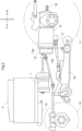
FIG. 2 is a left side view showing an arrangement of a motor and a travel battery. -
FIG. 3 is a schematic diagram showing a flow of power transmission. -
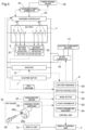
FIG. 4 is a functional block diagram showing functional units of a battery system. -
FIG. 5 is a chart illustrating an example of a flow in a control system. - An embodiment for carrying out the present invention will be described with reference to the drawings. In the following description, unless particularly specified otherwise, the arrow F shown in the drawings indicates the "forward direction", the arrow B indicates the "rearward direction", the arrow L indicates the "leftward direction", and the arrow R indicates the "rightward direction". The arrow U shown in the drawings indicates the "upward direction", and the arrow D indicates the "downward direction".
- A tractor as an example of an electric work vehicle according to the present invention will be described below. As shown in
FIG. 1 , the tractor includes left and rightfront wheels 10, left and rightrear wheels 11, and acover member 12. - The tractor includes a
body frame 2 and adriving section 3. Thebody frame 2 is supported by the left and rightfront wheels 10 and the left and rightrear wheels 11. Thecover member 12 is disposed at a front portion of the body. Thedriving section 3 is disposed rearward of thecover member 12. - The
driving section 3 includes aprotection frame 30, a driver'sseat 31, and asteering wheel 32. Thesteering wheel 32 can be operated by a driver riding on thedriving section 3 and seating in the driver'sseat 31. The left and rightfront wheels 10 are steered by operating thesteering wheel 32. Afront panel 13 is provided forward of the driver'sseat 31, and a part of thefront panel 13 is formed as ameter panel 13a. Adisplay unit 70 for notifying the driver of various types of information is incorporated in themeter panel 13a. The driver can perform various driving operations in thedriving section 3. - The tractor includes a
battery 4 serving as a travel battery. Thecover member 12 is swingable to be opened and closed about an opening and closing axis Q extending in the left-right direction of the body. While thecover member 12 is closed, thebattery 4 is covered by thecover member 12. On a left side surface of a front portion of thecover member 12, a chargingcover 12a is provided in such a manner as to be swingable to be opened and closed. As a result of the chargingcover 12a being opened, a chargingpower connector 44 to which a power feeding cable is inserted during charging is exposed. - As shown in
FIG. 2 , the tractor includes aninverter 14 and anelectric motor 1. Thebattery 4 supplies electric power to theinverter 14. Theinverter 14 converts direct-current power supplied from thebattery 4 into alternating-current power, thus generating driving power to be supplied to theelectric motor 1. The driving power is the alternating-current power generated by theinverter 14. - As shown in
FIGS. 2 and3 , the tractor includes a hydrostatic continuouslyvariable transmission device 15 and atransmission 16. As shown inFIG. 3 , the hydrostatic continuouslyvariable transmission device 15 includes ahydraulic pump 15a and ahydraulic motor 15b. - The
hydraulic pump 15a is driven by rotational power supplied from theelectric motor 1. As a result of thehydraulic pump 15a being driven, the rotational power is output from thehydraulic motor 15b. Note that the hydrostatic continuouslyvariable transmission device 15 is configured in such a manner that the rotational power is changed in speed in a continuously variable manner between thehydraulic pump 15a and thehydraulic motor 15b. - The rotational power output from the
hydraulic motor 15b is transmitted to thetransmission 16. The rotational power transmitted to thetransmission 16 is changed in speed by a geared transmission mechanism included in thetransmission 16, and is distributed to the left and rightfront wheels 10 and the left and rightrear wheels 11. Thus, the left and rightfront wheels 10 and the left and rightrear wheels 11 are driven. - As shown in
FIG. 3 , the tractor includes amid PTO shaft 17 and arear PTO shaft 18. The rotational power output from theelectric motor 1 is distributed to thehydraulic pump 15a, themid PTO shaft 17, and therear PTO shaft 18. Thus, themid PTO shaft 17 and therear PTO shaft 18 are rotated. - When a work device is connected to the
mid PTO shaft 17 or therear PTO shaft 18, the work device is driven by the rotational power of themid PTO shaft 17 or therear PTO shaft 18. For example, in the present embodiment, amowing device 19 is connected to themid PTO shaft 17 as shown inFIG. 2 . Themowing device 19 is driven by the rotational power of themid PTO shaft 17. -
FIG. 4 schematically shows a configuration relating to control of thebattery 4 and theelectric motor 1. The motor and battery control system includes anaccelerator device 33, akey device 34, acontrol unit 6, and aninverter 14. Thecontrol unit 6 controls the operation of theelectric motor 1. Theaccelerator device 33 is provided in the vicinity of thesteering wheel 32. Although the structure of theaccelerator device 33 is not shown, theaccelerator device 33 includes a swingably operable lever , and a potentiometer configured to be operated by the swinging operation of the lever. Theaccelerator device 33 is connected to thecontrol unit 6. - The
key device 34 is also connected to thecontrol unit 6. Thekey device 34 is provided on thefront panel 13, and is configured to perform an ON operation and an OFF operation on thecontrol unit 6. In this embodiment, thekey device 34 is composed of acontrol state switcher 35 and aportable operation key 36. Aninsertion portion 35a to which the operation key 36 configured to be inserted and mounted, and a push-button switch 35b configured to be manually pushed are attached to thecontrol state switcher 35. Theoperation key 36 and theswitch 35b function as a manual operation device of the present invention. In this embodiment, a pressing operation on theswitch 35b while theoperation key 36 is inserted and mounted to theinsertion portion 35a is regarded as a first operation (ON operation) on the manual operation device. In addition, a further pressing operation on theswitch 35b while theoperation key 36 is inserted and mounted to theinsertion portion 35a is regarded as a second operation (OFF operation) on the manual operation device. In response to the first operation on the manual operation device, thecontrol state switcher 35 sends a switching signal for switching thecontrol unit 6 to an operating state (powered-on state: ON state) to thecontrol unit 6. In response to the second operation on the manual operation device, thecontrol state switcher 35 sends a switching signal for switching thecontrol unit 6 to a resting state (powered-off state: OFF state) to thecontrol unit 6. Note that, similarly to a general vehicle key, the operation key 36 functions as a key that can be identified only by the work vehicle. - The
control unit 6 is further connected to theinverter 14, and provides a drive instruction to theinverter 14 in response to an instruction provided by theaccelerator device 33. In response to the instruction provided by thecontrol unit 6, theinverter 14 adjusts the electric power supplied from thebattery 4 to theelectric motor 1 and controls the output of theelectric motor 1. - The
control unit 6 is also connected to the display control unit 7. Through devices, such as thedisplay unit 70, a lamp, and a buzzer, incorporated in themeter panel 13a to notify the driver of information, the display control unit 7 notifies the driver of, for example, the traveling state, the work state, the battery information (e.g., the charge amount and the temperature) in a visual or auditory manner. - Charging of the
battery 4 is performed by a chargingcontroller 43 from apower feeding device 45 connected to the chargingpower connector 44. The chargingpower connector 44 is provided with a power feeding socket, and the power feeding socket is connected to a power feeding connector of a charging cable from thepower feeding device 45 during charging. - The
battery 4 is, for example, a lithium ion battery, and includesbattery cells 40 serving as low-voltage, small unit cells stacked in multiple layers. Thebattery state detector 5 configured to detect the battery state includes abattery voltage detector 51 and abattery temperature detector 52. Thebattery voltage detector 51 can detect, as a cell voltage, the voltages between a plurality ofbattery cells 40 connected in series. Detection signals of thebattery voltage detector 51 and thebattery temperature detector 52 are sent to thecontrol unit 6. - The tractor includes, in addition to the
battery 4, anelectric component battery 41 that supplies electric power to thecontrol unit 6 and other electric components. Theelectric component battery 41 supplies low-voltage (12-volt) electric power for driving the electric components. Theelectric component battery 41 is charged by the electric power supplied from thebattery 4 via a DC/DC converter 42. The driving of the DC/DC converter 42 is controlled by thecontrol unit 6. - The
control unit 6 includes, as functional elements particularly related to the present invention, abattery manager 60, amotor controller 61, amode setter 62, astart prohibitor 63, and astart prohibition releaser 64. - The
control unit 6 can be set to a charging mode to enable charging of thebattery 4, and a work mode to enable driving of theelectric motor 1. These two modes are set by themode setter 62. - The start prohibitor 63 prohibits starting of the
electric motor 1. Thestart prohibition releaser 64 releases the prohibition on starting of thestart prohibitor 63 by theelectric motor 1. For example, in one application example of the prohibition on starting of the electric motor, thestart prohibitor 63 prohibits starting of theelectric motor 1 after charging of thebattery 4 has ended. Accordingly, after the end of charging, theelectric motor 1 will not start unless some sort of special operation is performed, thus inhibiting theft of the tractor for which charging has ended. In another application example, in response to detection of the power feeding connector of the charging cable from thepower feeding device 45 being inserted to the power feeding socket of the chargingpower connector 44, thestart prohibitor 63 prohibits starting of theelectric motor 1. Accordingly, theelectric motor 1 will not start while the power feeding connector of the charging cable is inserted to the chargingpower connector 44. In each case, the prohibition on starting of theelectric motor 1 by theprohibitor 63 is released by an operation performed by the driver (manager) using the manual operation device, for example, thestart prohibition releaser 64 that has received an acknowledgement signal for an operation into the first operation. - The
battery manager 60 manages charging and discharging of thebattery 4, for example, based on the cell voltage, the overall inverter voltage, the converter input voltage, and a signal from thekey device 34. For example, in response to detection of the power feeding connector of the charging cable from thepower feeding device 45 being inserted to the power feeding socket of the chargingpower connector 44, and detection of the manual operation device being operated from the second operation state to the first operation, themode setter 62 sets thecontrol unit 6 to the charging mode. More specifically, in response to the power feeding connector of the charging cable being inserted to the chargingpower connector 44, thecontrol unit 6 enters a charging standby state. In this charging standby state, in response to thecontrol state switcher 35 sending a switching signal (first operation functioning as a charging start instruction) to thecontrol unit 6 through an operation on thekey device 34, thecontrol unit 6 enters the charging mode, and a charging program of the chargingcontroller 43 is executed, whereby a charging process of thebattery 4 is started. In response to the charging process of thebattery 4 having ended, and thecontrol state switcher 35 sending, to thecontrol unit 6, a switching signal (second operation) for switching thecontrol unit 6 to the resting state, thecontrol unit 6 is powered off and enters the resting state. In response to the first operation using the manual operation device being performed during charging, thecontrol unit 6 enters the charging standby state, whereby the charging process is interrupted. - In this embodiment, while the charging cable is inserted to the charging
power connector 44, thecontrol unit 6 is switched from the resting state to the operating state through, for example, the first operation using the manual operation device, whereby a charging start instruction is issued and charging is started. At that time, even in a case where the first operation using the manual operation device is performed in order to start charging, it is deemed that some abnormality has occurred in a case where charging of thebattery 4 is not started. In order to avoid a secondary problem due to the occurrence of such abnormality, even in a case where a charging start instruction is issued, thecontrol unit 6 may be switched to the resting state to power off thecontrol unit 6 in a case where charging of thebattery 4 is not started within a predetermined time after the first operation. Note that another operation method may be used as the operation for starting charging, or another operation device may be used. - The
motor controller 61 controls the driving of theelectric motor 1. Specifically, based on a signal from theaccelerator device 33, themotor controller 61 generates a drive signal for driving theelectric motor 1, and provides the signal to theinverter 14. - In the control system, including the
control unit 6, installed in the tractor, various processes relating to battery charging and electric motor control can be executed. Such control processes will be listed below. - (1) If the second operation state (OFF state) provided using the manual operation device is maintained when charging of the
battery 4 has ended, thecontrol unit 6 is powered off. - (2) If the first operation state (ON state) provided using the manual operation device is maintained when charging of the
battery 4 has ended, thecontrol unit 6 is powered off (OFF state) after an elapse of a predetermined time. - (3) Even in a case where a motor start instruction is issued in the work mode to enable traveling control, the
control unit 6 is powered off after a predetermined waiting time (e.g., after 5 seconds) in a case where theelectric motor 1 does not transition to a starting state. - (4) In a case where the electric motor has stopped due to the occurrence of an error, the
control unit 6 is powered off in order to avoid any influence on the control system including thecontrol unit 6 as a core. - (5) In response to the power feeding line from the
power feeding device 45 being connected to the chargingpower connector 44, starting of theelectric motor 1 is prohibited. In addition to this, if theelectric motor 1 is in the operating state, theelectric motor 1 enters a stopped state. The prohibition on starting of theelectric motor 1 and the stopped state of theelectric motor 1 may also be handled equally. - (6) In a case where the battery state deteriorates, for example, where the battery voltage is reduced or the battery temperature is increased, the output from the
electric motor 1 is limited to a preset output limit value. - Next, an example of the flow of control performed in the
control unit 6 will be described using the chart shown inFIG. 5 . In this chart, the state of thecontrol unit 6 is divided into a resting state in which thecontrol unit 6 is powered off, and an operating state in which power is connected to thecontrol unit 6. Furthermore, the operating state is divided into a work mode to enable traveling of the tractor, and a charging mode to enable charging of thebattery 4. - The tractor parked in the resting state transitions to the operating state by an ON operation performed on the key device 34 (#a). The ON operation on the
key device 34 triggers control by thecontrol unit 6, whereby initial processes of various functions are executed (#b). When the initial processes have ended, whether the system is in a state in which connection for charging is not performed (connection for charging is not established), or a state in which connection for charging is performed (connection for charging is established). - If connection for charging is not established (#c1), the tractor enters the work mode and waits. When a motor start instruction has been issued (#d), whether the motor is in a starting state or a non-starting state is checked. If the motor is in the starting state (#d1), the tractor enters the traveling state (including temporary stopping) (#e). In the traveling state of the tractor, in response to an OFF operation on the
key device 34 and connection for charging being detected (#e 1), and in response to the occurrence of a severe error including a battery operation failure (#e2), a parking process (stopping process) (#f) is performed. When the parking process has been completed (#g), thecontrol unit 6 is powered off and enters in the resting state, whereby the tractor enters a parking state. Despite a motor start instruction being issued (#d), in a case where the motor does not enter the starting state after an elapse of a predetermined time (#d2), the procedure proceeds to the parking process (stopping process) (#f), and the system enters the resting state. - After the initial processes (#b) have ended, in response to the charging cable from the
power feeding device 45 being connected to the chargingpower connector 44, the system enters the charging standby state (#h). In the charging standby state, in response to an ON operation being performed on thekey device 34 from the OFF operation state, a charging start instruction issued (#i1), and the system enters the charging mode. That is, in order for the system to transition to the charging mode after the charging cable from thepower feeding device 45 has been connected to the chargingpower connector 44, an operation from the OFF operation into the ON operation on thekey device 34 needs to be performed. - When the system has transitioned to the charging mode, the charging process of the
battery 4 is performed by the charging controller 43 (#j). During the charging process, thecontrol unit 6 is connected to power. When the charging process has ended, thestart prohibitor 63 prohibits starting of the electric motor 1 (#l). If the state of operation on thekey device 34 is in the OFF operation state (#m 1) at the time when the charging process has ended, thecontrol unit 6 is powered off and enters the resting state, whereby the tractor enters the parking state. If the state of operation on thekey device 34 is the ON operation state (#m2) at the time when the charging process has ended, after an elapse of a predetermined time (e.g., after 1 minute) (#m3), the state of operation on thekey device 34 is forcibly brought into the OFF operation state (#m4). Thus, thecontrol unit 6 is powered off and enters the resting state, whereby the tractor enters the parking state. - Despite a charging start instruction being issued, if charging is not started (#k), after an elapse of a predetermined time (#n), the
control unit 6 is powered off and enters the resting state, whereby the tractor enters the parking state. - In the charging standby state, the state in which connection for charging is not established without the charging cable being connected continues for a predetermined time (e.g., 5 seconds) (#i2) while the
key device 34 is in the OFF operation state, the system does not transition to the charging mode, and thecontrol unit 6 is powered off and enters the resting state, whereby the tractor enters the parking state. - If the
electric motor 1 is in the driving state at the time when the charging cable from thepower feeding device 45 has been connected to the chargingpower connector 44, thecontrol unit 6 causes theelectric motor 1 to enter the stopped state (non-driving state). At that time, thestart prohibitor 63 may also function to prohibit starting of theelectric motor 1. Of course, the transition to the stopped state (non-driving state) of theelectric motor 1, and the prohibition on starting of theelectric motor 1 may both be performed by thestart prohibitor 63. The stopping and the prohibition on starting of theelectric motor 1 can be realized by stopping supply of power to theelectric motor 1, but may be realized by stopping theinverter 14. -
- (1) In the above embodiment, the manual operation device of the
key device 34 is composed of the operation key 36 configured to be inserted and mounted to theinsertion portion 35a, and theswitch 35b; however, in place of this configuration, the manual operation device may perform the ON operation and the OFF operation via wireless communication. Thekey device 34 may be configured in any manner. - (2) The functional blocks of the functional block diagram shown in
FIG. 4 may each be divided into a plurality of blocks, or may be configured by a plurality of functional blocks integrated in one piece. - Note that the configurations disclosed in the embodiments described above (including the alternative embodiments; the same applies to the following) are applicable in combination with configurations disclosed in other embodiments so long as no inconsistency arises. The embodiments disclosed herein are illustrative, and embodiments of the present invention are not limited thereto. Appropriate changes and modifications may be made without departing from the scope and sprit of the present invention.
- The present invention is applicable not only to a tractor, but also to various electric work vehicles such as a rice planter, a combine, and a construction machine.
-
- 1: Electric motor
- 2: Body frame
- 3: Driving section
- 4: Battery
- 5: Battery state detector
- 6: Control unit
- 7: Display control unit
- 10: Front wheel
- 11: Rear wheel
- 12: Cover member
- 13: Front panel
- 13a: Meter panel
- 14: Inverter
- 15: Hydrostatic continuously variable transmission device
- 15a: Hydraulic pump
- 15b: Hydraulic motor
- 16: Transmission
- 17: Mid PTO shaft
- 18: Rear PTO shaft
- 19: Mowing device
- 30: Protection frame
- 31: Driver's seat
- 32: Steering wheel
- 33: Accelerator device
- 34: Key device
- 35: Control state switcher
- 35a: Insertion portion
- 35b: Switch
- 36: Operation key
- 40: Battery cell
- 41: Electric component battery
- 42: DC/DC converter
- 43: Charging controller
- 44: Charging power connector
- 45: Power feeding device
- 51: Battery voltage detector
- 52: Battery temperature detector
- 60: Battery manager
- 61: Motor controller
- 62: Mode setter
- 63: Start prohibitor
- 64: Start prohibition releaser
- 70: Display unit
Claims (9)
- An electric work vehicle configured to be driven by power of an electric motor powered from a chargeable battery, the electric work vehicle comprising:a control unit configured to control the electric work vehicle;a control state switcher configured to switch the control unit to an operating state in response to a first operation on a manual operation device, and switch the control unit to a resting state in response to a second operation on the manual operation device;a charging power connector configured to receive charging power to be supplied to the battery; anda charging controller configured to control charging of the battery with the charging power, whereinthe control unit includes:a motor controller configured to control driving of the electric motor;a mode setter configured to set a charging mode to enable charging of the battery, and a work mode to enable driving of the electric motor;a start prohibitor configured to prohibit starting of the electric motor after charging has ended; anda start prohibition releaser configured to release the prohibition on starting of the electric motor.
- The electric work vehicle according to claim 1, wherein the prohibition on starting by the start prohibitor is released by an operation into the first operation on the manual operation device.
- The electric work vehicle according to claim 1 or 2, wherein the control unit is powered off in a case where charging of the battery is not started within a predetermined time after a charging start instruction has been provided during the charging mode.
- The electric work vehicle according to any one of claims 1 to 3, wherein the control unit is powered off in a case where a state of the second operation using the manual operation device is maintained after charging of the battery has ended.
- The electric work vehicle according to any one of claims 1 to 4, wherein the control unit is powered off after an elapse of a predetermined time in a case where a state of the first operation using the manual operation device is maintained after charging of the battery has ended.
- The electric work vehicle according to any one of claims 1 to 5, wherein the control unit is powered off after an elapse of a predetermined waiting time in a case where the electric motor does not transition to a starting state after a motor start instruction has been provided in the work mode.
- The electric work vehicle according to any one of claims 1 to 6, wherein the control unit is powered off in a case where the electric motor is stopped due to occurrence of an error.
- The electric work vehicle according to any one of claims 1 to 7, wherein the control unit causes the electric motor to enter a stopped state in response to a power feeding line from a power feeding device being connected to the charging power connector.
- The electric work vehicle according to any one of claims 1 to 8, wherein the charging mode is set by the charging power connector being connected for charging, and the manual operation device being operated from a state of the second operation into the first operation.
Applications Claiming Priority (2)
| Application Number | Priority Date | Filing Date | Title |
|---|---|---|---|
| JP2022130930A JP7822279B2 (en) | 2022-08-19 | 2022-08-19 | electric work vehicle |
| PCT/JP2023/004876 WO2024038627A1 (en) | 2022-08-19 | 2023-02-14 | Electric work vehicle |
Publications (1)
| Publication Number | Publication Date |
|---|---|
| EP4574540A1 true EP4574540A1 (en) | 2025-06-25 |
Family
ID=89941628
Family Applications (1)
| Application Number | Title | Priority Date | Filing Date |
|---|---|---|---|
| EP23854667.5A Pending EP4574540A1 (en) | 2022-08-19 | 2023-02-14 | Electric work vehicle |
Country Status (5)
| Country | Link |
|---|---|
| US (1) | US20250178457A1 (en) |
| EP (1) | EP4574540A1 (en) |
| JP (1) | JP7822279B2 (en) |
| CN (1) | CN119789971A (en) |
| WO (1) | WO2024038627A1 (en) |
Families Citing this family (3)
| Publication number | Priority date | Publication date | Assignee | Title |
|---|---|---|---|---|
| JP2023110657A (en) * | 2022-01-28 | 2023-08-09 | 株式会社クボタ | electric work vehicle |
| KR20250060527A (en) * | 2023-10-26 | 2025-05-07 | 현대자동차주식회사 | Method to switch the starting mode from the reserved air conditioning mode of an electric vehicle and system for the same |
| WO2026004292A1 (en) * | 2024-06-26 | 2026-01-02 | 株式会社クボタ | Work machine |
Family Cites Families (9)
| Publication number | Priority date | Publication date | Assignee | Title |
|---|---|---|---|---|
| JP4879231B2 (en) | 2008-07-14 | 2012-02-22 | 日立建機株式会社 | Battery-powered construction machinery |
| JP2010182239A (en) | 2009-02-09 | 2010-08-19 | Denso Corp | Plug-in vehicle management system |
| JP5522115B2 (en) * | 2011-04-27 | 2014-06-18 | 株式会社デンソー | Charge control device |
| JP5836033B2 (en) | 2011-09-22 | 2015-12-24 | 株式会社クボタ | Tractor power extraction structure |
| US9106162B2 (en) * | 2012-08-31 | 2015-08-11 | Ford Global Technologies, Llc | Control strategy for an electric machine in a vehicle |
| JP6099743B2 (en) * | 2013-06-07 | 2017-03-22 | 三菱電機株式会社 | Charge / discharge control device and electric vehicle |
| US11186198B2 (en) * | 2019-05-31 | 2021-11-30 | Ford Global Technologies, Llc | Methods and systems for vehicle battery cell failure detection and overcharge protection |
| JP7304750B2 (en) | 2019-06-24 | 2023-07-07 | 株式会社クボタ | electric work vehicle |
| KR102723907B1 (en) * | 2019-10-23 | 2024-10-31 | 현대자동차주식회사 | Vehicle and method of controlling the same |
-
2022
- 2022-08-19 JP JP2022130930A patent/JP7822279B2/en active Active
-
2023
- 2023-02-14 EP EP23854667.5A patent/EP4574540A1/en active Pending
- 2023-02-14 WO PCT/JP2023/004876 patent/WO2024038627A1/en not_active Ceased
- 2023-02-14 CN CN202380060722.3A patent/CN119789971A/en active Pending
-
2025
- 2025-02-11 US US19/050,297 patent/US20250178457A1/en active Pending
Also Published As
| Publication number | Publication date |
|---|---|
| WO2024038627A1 (en) | 2024-02-22 |
| JP7822279B2 (en) | 2026-03-02 |
| JP2024027806A (en) | 2024-03-01 |
| CN119789971A (en) | 2025-04-08 |
| US20250178457A1 (en) | 2025-06-05 |
Similar Documents
| Publication | Publication Date | Title |
|---|---|---|
| US20250178457A1 (en) | Electric work vehicle | |
| US9090177B2 (en) | Uncertified battery replacement countermeasure apparatus for electric vehicle | |
| EP2778002B1 (en) | Hybrid vehicle | |
| JP6710581B2 (en) | Vehicle battery over-discharge prevention device and method | |
| US20130204473A1 (en) | Method for charging a battery of a motor vehicle, and motor vehicle | |
| CN106164384A (en) | construction machinery | |
| KR102221165B1 (en) | Safety device and control method for construction machinery | |
| WO2013121614A1 (en) | Charge/discharge control device for electric accumulator, charge/discharge control method for electric accumulator, and hybrid work machine provided with charge/discharge control device for electric accumulator | |
| JP7825667B2 (en) | electric work vehicle | |
| JP7311471B2 (en) | work vehicle | |
| CN112606814A (en) | Trailer mode control method and device | |
| JP2024120921A5 (en) | ||
| JP2010022164A (en) | Battery drive type construction machine | |
| JP4453683B2 (en) | Remote control device | |
| EP2474433B1 (en) | Electrically-driven vehicle | |
| JP2017128186A (en) | Plug-in hybrid work vehicle | |
| CN115715262B (en) | Safe parking system | |
| JP5998672B2 (en) | Movement restriction device when charging cable of vehicle is connected | |
| US20240308385A1 (en) | Robust vehicle securement techniques for vehicle-to-everything power generation | |
| JP2022103937A (en) | Emergency stop device of vehicle | |
| JP7519984B2 (en) | Electric work vehicle | |
| US12630116B2 (en) | Control device and control system | |
| US20250263045A1 (en) | Control device and control system | |
| US20240308389A1 (en) | Electric work vehicle | |
| US20260103166A1 (en) | Enhanced vehicle securement system |
Legal Events
| Date | Code | Title | Description |
|---|---|---|---|
| STAA | Information on the status of an ep patent application or granted ep patent |
Free format text: STATUS: THE INTERNATIONAL PUBLICATION HAS BEEN MADE |
|
| PUAI | Public reference made under article 153(3) epc to a published international application that has entered the european phase |
Free format text: ORIGINAL CODE: 0009012 |
|
| STAA | Information on the status of an ep patent application or granted ep patent |
Free format text: STATUS: REQUEST FOR EXAMINATION WAS MADE |
|
| 17P | Request for examination filed |
Effective date: 20250213 |
|
| AK | Designated contracting states |
Kind code of ref document: A1 Designated state(s): AL AT BE BG CH CY CZ DE DK EE ES FI FR GB GR HR HU IE IS IT LI LT LU LV MC ME MK MT NL NO PL PT RO RS SE SI SK SM TR |
|
| DAV | Request for validation of the european patent (deleted) | ||
| DAX | Request for extension of the european patent (deleted) |