EP4574521A1 - Electrical system of electric vehicle, and methods for controlling power-on process and power-off process of electric vehicle - Google Patents
Electrical system of electric vehicle, and methods for controlling power-on process and power-off process of electric vehicle Download PDFInfo
- Publication number
- EP4574521A1 EP4574521A1 EP24216611.4A EP24216611A EP4574521A1 EP 4574521 A1 EP4574521 A1 EP 4574521A1 EP 24216611 A EP24216611 A EP 24216611A EP 4574521 A1 EP4574521 A1 EP 4574521A1
- Authority
- EP
- European Patent Office
- Prior art keywords
- voltage
- bus
- battery pack
- precharging
- negative
- Prior art date
- Legal status (The legal status is an assumption and is not a legal conclusion. Google has not performed a legal analysis and makes no representation as to the accuracy of the status listed.)
- Pending
Links
Images


Classifications
-
- B—PERFORMING OPERATIONS; TRANSPORTING
- B60—VEHICLES IN GENERAL
- B60L—PROPULSION OF ELECTRICALLY-PROPELLED VEHICLES; SUPPLYING ELECTRIC POWER FOR AUXILIARY EQUIPMENT OF ELECTRICALLY-PROPELLED VEHICLES; ELECTRODYNAMIC BRAKE SYSTEMS FOR VEHICLES IN GENERAL; MAGNETIC SUSPENSION OR LEVITATION FOR VEHICLES; MONITORING OPERATING VARIABLES OF ELECTRICALLY-PROPELLED VEHICLES; ELECTRIC SAFETY DEVICES FOR ELECTRICALLY-PROPELLED VEHICLES
- B60L3/00—Electric devices on electrically-propelled vehicles for safety purposes; Monitoring operating variables, e.g. speed, deceleration or energy consumption
- B60L3/0023—Detecting, eliminating, remedying or compensating for drive train abnormalities, e.g. failures within the drive train
- B60L3/0046—Detecting, eliminating, remedying or compensating for drive train abnormalities, e.g. failures within the drive train relating to electric energy storage systems, e.g. batteries or capacitors
-
- B—PERFORMING OPERATIONS; TRANSPORTING
- B60—VEHICLES IN GENERAL
- B60L—PROPULSION OF ELECTRICALLY-PROPELLED VEHICLES; SUPPLYING ELECTRIC POWER FOR AUXILIARY EQUIPMENT OF ELECTRICALLY-PROPELLED VEHICLES; ELECTRODYNAMIC BRAKE SYSTEMS FOR VEHICLES IN GENERAL; MAGNETIC SUSPENSION OR LEVITATION FOR VEHICLES; MONITORING OPERATING VARIABLES OF ELECTRICALLY-PROPELLED VEHICLES; ELECTRIC SAFETY DEVICES FOR ELECTRICALLY-PROPELLED VEHICLES
- B60L1/00—Supplying electric power to auxiliary equipment of vehicles
-
- B—PERFORMING OPERATIONS; TRANSPORTING
- B60—VEHICLES IN GENERAL
- B60L—PROPULSION OF ELECTRICALLY-PROPELLED VEHICLES; SUPPLYING ELECTRIC POWER FOR AUXILIARY EQUIPMENT OF ELECTRICALLY-PROPELLED VEHICLES; ELECTRODYNAMIC BRAKE SYSTEMS FOR VEHICLES IN GENERAL; MAGNETIC SUSPENSION OR LEVITATION FOR VEHICLES; MONITORING OPERATING VARIABLES OF ELECTRICALLY-PROPELLED VEHICLES; ELECTRIC SAFETY DEVICES FOR ELECTRICALLY-PROPELLED VEHICLES
- B60L3/00—Electric devices on electrically-propelled vehicles for safety purposes; Monitoring operating variables, e.g. speed, deceleration or energy consumption
- B60L3/0023—Detecting, eliminating, remedying or compensating for drive train abnormalities, e.g. failures within the drive train
- B60L3/0069—Detecting, eliminating, remedying or compensating for drive train abnormalities, e.g. failures within the drive train relating to the isolation, e.g. ground fault or leak current
-
- H—ELECTRICITY
- H02—GENERATION; CONVERSION OR DISTRIBUTION OF ELECTRIC POWER
- H02H—EMERGENCY PROTECTIVE CIRCUIT ARRANGEMENTS
- H02H9/00—Emergency protective circuit arrangements for limiting excess current or voltage without disconnection
- H02H9/001—Emergency protective circuit arrangements for limiting excess current or voltage without disconnection limiting speed of change of electric quantities, e.g. soft switching on or off
-
- B—PERFORMING OPERATIONS; TRANSPORTING
- B60—VEHICLES IN GENERAL
- B60L—PROPULSION OF ELECTRICALLY-PROPELLED VEHICLES; SUPPLYING ELECTRIC POWER FOR AUXILIARY EQUIPMENT OF ELECTRICALLY-PROPELLED VEHICLES; ELECTRODYNAMIC BRAKE SYSTEMS FOR VEHICLES IN GENERAL; MAGNETIC SUSPENSION OR LEVITATION FOR VEHICLES; MONITORING OPERATING VARIABLES OF ELECTRICALLY-PROPELLED VEHICLES; ELECTRIC SAFETY DEVICES FOR ELECTRICALLY-PROPELLED VEHICLES
- B60L2210/00—Converter types
- B60L2210/10—DC to DC converters
-
- B—PERFORMING OPERATIONS; TRANSPORTING
- B60—VEHICLES IN GENERAL
- B60L—PROPULSION OF ELECTRICALLY-PROPELLED VEHICLES; SUPPLYING ELECTRIC POWER FOR AUXILIARY EQUIPMENT OF ELECTRICALLY-PROPELLED VEHICLES; ELECTRODYNAMIC BRAKE SYSTEMS FOR VEHICLES IN GENERAL; MAGNETIC SUSPENSION OR LEVITATION FOR VEHICLES; MONITORING OPERATING VARIABLES OF ELECTRICALLY-PROPELLED VEHICLES; ELECTRIC SAFETY DEVICES FOR ELECTRICALLY-PROPELLED VEHICLES
- B60L2210/00—Converter types
- B60L2210/10—DC to DC converters
- B60L2210/14—Boost converters
-
- B—PERFORMING OPERATIONS; TRANSPORTING
- B60—VEHICLES IN GENERAL
- B60L—PROPULSION OF ELECTRICALLY-PROPELLED VEHICLES; SUPPLYING ELECTRIC POWER FOR AUXILIARY EQUIPMENT OF ELECTRICALLY-PROPELLED VEHICLES; ELECTRODYNAMIC BRAKE SYSTEMS FOR VEHICLES IN GENERAL; MAGNETIC SUSPENSION OR LEVITATION FOR VEHICLES; MONITORING OPERATING VARIABLES OF ELECTRICALLY-PROPELLED VEHICLES; ELECTRIC SAFETY DEVICES FOR ELECTRICALLY-PROPELLED VEHICLES
- B60L2240/00—Control parameters of input or output; Target parameters
- B60L2240/40—Drive Train control parameters
- B60L2240/54—Drive Train control parameters related to batteries
- B60L2240/547—Voltage
-
- B—PERFORMING OPERATIONS; TRANSPORTING
- B60—VEHICLES IN GENERAL
- B60L—PROPULSION OF ELECTRICALLY-PROPELLED VEHICLES; SUPPLYING ELECTRIC POWER FOR AUXILIARY EQUIPMENT OF ELECTRICALLY-PROPELLED VEHICLES; ELECTRODYNAMIC BRAKE SYSTEMS FOR VEHICLES IN GENERAL; MAGNETIC SUSPENSION OR LEVITATION FOR VEHICLES; MONITORING OPERATING VARIABLES OF ELECTRICALLY-PROPELLED VEHICLES; ELECTRIC SAFETY DEVICES FOR ELECTRICALLY-PROPELLED VEHICLES
- B60L2270/00—Problem solutions or means not otherwise provided for
- B60L2270/20—Inrush current reduction, i.e. avoiding high currents when connecting the battery
Definitions
- the disclosure relates to the field of vehicle control technologies, and in particular to an electrical system of an electric vehicle, and methods for controlling a power-on process and a power-off process of an electric vehicle.
- VCU vehicle control unit
- BMS battery management system
- the vehicle control unit requests the BMS to close a main relay.
- the BMS then successively closes a main negative relay and a precharging relay.
- the BMS closes a main positive relay and opens the precharging relay.
- a power-off process of the vehicles includes shutting down various onboard electrical devices, disconnecting a battery from an electrical load, and other operations, to avoid safety problems such as battery over-discharge or electrical fires.
- An objective of the disclosure is to provide an electrical system of an electric vehicle, and methods for controlling a power-on process and a power-off process of an electric vehicle, which may enhance the efficiency, speed, and safety of the power-on process and the power-off process.
- an electrical system of an electric vehicle includes:
- the main controller is further configured to perform the following operations:
- the high-voltage unit includes:
- the local controller is further configured to send to the main controller a first message indicating that the main positive relay is in a closed state.
- the main controller is further configured to, in operation A, send to the local controller a third command to close the main negative relay after the low-voltage battery pack starts charging the precharging capacitor; and the local controller is further configured to, in response to the third command, enable the main negative relay to be in a closed state, and send to the main controller a second message indicating the bus voltage.
- the local controller is a battery management system.
- the main controller is further configured to perform operation C as follows:
- a method for controlling a power-on process of an electric vehicle includes an electrical system.
- the electrical system includes a main controller, a low-voltage battery pack, a high-voltage bus, a negative bus, a high-voltage unit, a DC-DC converter connected between the high-voltage bus and the negative bus, and a precharging capacitor connected between the high-voltage bus and the negative bus.
- the high-voltage unit includes a high-voltage battery pack connected to the high-voltage bus and to the negative bus.
- the method includes:
- the method further includes:
- step A' the main controller sends to the local controller a third command to close the main negative relay after the low-voltage battery pack starts charging the precharging capacitor, and the local controller, in response to the third command, enables the main negative relay to be in a closed state, and sends to the main controller a second message indicating the bus voltage.
- a method for controlling a power-off process of an electric vehicle includes an electrical system.
- the electrical system includes a main controller, a low-voltage battery pack, a high-voltage bus, a negative bus, a high-voltage unit, a DC-DC converter connected between the high-voltage bus and the negative bus, and a precharging capacitor connected between the high-voltage bus and the negative bus.
- the high-voltage unit includes a high-voltage battery pack connected to the high-voltage bus and to the negative bus.
- the method includes:
- the high-voltage unit further includes a local controller, a main positive relay connected between the high-voltage bus and the positive electrode of the high-voltage battery pack and controlled by the local controller, and a main negative relay connected between the negative bus and a negative electrode of the high-voltage battery pack and controlled by the local controller.
- Step A" includes:
- the method further includes: C". sending, by the main controller, to an onboard device a fourth command to enter a shutdown state over an in-vehicle network after it is determined that the bus voltage is reduced to the target discharging voltage or below.
- capacitor charging is used as a precharging manner, thereby improving the charging speed and efficiency, and making it easier to integrate a precharging component into a device such as a power electronic unit.
- the bus voltage after precharging is also compared with an output voltage of the high-voltage battery pack. Such "double" checking reduces the possibility that a large impulse current is generated when the high-voltage battery pack is connected to the high-voltage bus.
- insulation detection is performed during the power-off process, thereby improving the safety of a vehicle system.
- connection refers to an electrical connection for power transmission or a communication connection for signal transmission between two or more hardware entities, which includes a direct connection between two hardware entities, and a connection between two hardware entities via another hardware entity.
- the term "main controller” refers to a controller for controlling one or more functional domains.
- the main controller may, for example, be a vehicle control unit (VCU) for coordinating the operation of each controller, to implement driving, braking, energy recovery, and other functions of a vehicle while monitoring the status and safety of the vehicle.
- VCU vehicle control unit
- An electric vehicle is usually divided into a plurality of functional domains according to functions (for example, a powertrain domain, a chassis domain, a cockpit domain, an autonomous driving domain, a vehicle body domain, etc.).
- a domain controller communicates with various sensors and actuators over communication networks such as a CAN, a LIN, and MOST, to implement control and management of specific functional domains.
- the domain controller may also be used as the main controller.
- the stable increase of voltage on the high-voltage side is usually implemented by means of a precharging resistor.
- the use of the precharging resistor has disadvantages of high energy consumption, difficulty in miniaturization (a large resistor is required due to the need for a large current), etc.
- the precharging is implemented by means of a capacitor, which has advantages of fast charging speed, high charging efficiency, easy integration, etc.
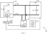
- FIG. 1 is a schematic diagram of an electrical system of an electric vehicle according to an embodiment of the disclosure.
- An electrical system 10 shown in FIG. 1 includes a main controller 110, a low-voltage battery pack 120, a high-voltage bus 130A, a negative bus 130B, a high-voltage unit 140, a power electronic unit (PEU) 150, and an intelligent power unit (IPU) 160.
- the high-voltage bus 130A and the negative bus 130B are collectively referred to as a direct-current bus below.
- the high-voltage unit 140 includes a high-voltage battery pack 141, a local controller 142, and relays 143A, 143B.
- a positive electrode and a negative electrode of the high-voltage battery pack 141 are respectively connected to the high-voltage bus 130A and the negative bus 130B via the relays 143A, 143B.
- the relay 143A is also referred to as a main positive relay below since it is connected between the positive electrode of the high-voltage battery pack 141 and the high-voltage bus 130A.
- the relay 143B is also referred to as a main negative relay below since it is connected between the negative electrode of the high-voltage battery pack 141 and the negative bus 130B.
- the power electronic unit 150 is an integrated drive system, and usually includes components such as an alternating current-direct current converter, a direct current-alternating current inverter, and a motor controller. In the embodiment shown in FIG. 1 , the power electronic unit 150 further includes a precharging capacitor 151, and the capacitor is connected between the high-voltage bus 130A and the negative bus 130B.
- the intelligent power unit (IPU) 160 is usually configured to implement functions such as motor control and power conversion. In addition, further control modules (such as a programmable logic controller and a microcontroller) may be added according to actual needs, to implement more complex control logic. In some specific implementations, as shown in FIG. 1 , the intelligent power unit (IPU) 160 includes a DC-DC converter 161, which is connected between the high-voltage bus 130A and the negative bus 130B and is configured to convert a low-voltage direct current of the low-voltage battery pack 120 into a high-voltage direct current and output the high-voltage direct current to the direct current bus, to charge the precharging capacitor 151.
- DC-DC converter 161 which is connected between the high-voltage bus 130A and the negative bus 130B and is configured to convert a low-voltage direct current of the low-voltage battery pack 120 into a high-voltage direct current and output the high-voltage direct current to the direct current bus, to charge the precharging capacitor 151.
- the IPU and the PEU differ in function, they overlap and complement each other to some extent.
- the IPU may be integrated with the PEU.
- it may also be necessary to configure both the IPU and the PEU.
- both the IPU and the PEU may be needed to implement more complex driving modes and control logic.
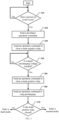
- FIG. 2 is a flowchart of a method for controlling a power-on process of an electric vehicle according to another embodiment of the disclosure.
- the method described below is implemented by the electrical system shown in FIG. 1 .
- implementation of the method shown in FIG. 2 is not limited to an electrical system having a specific structure.
- the method shown in FIG. 2 starts at step 210.
- the main controller 110 determines whether a set type of event (a power-on event) occurs. If the set type of event occurs, the method proceeds to step 220; otherwise, the power-on process is exited.
- a power-on request for example, a user power-on request, a remote control request, and firmware over-the-air (FOTA) may be sent to onboard devices such as a main controller, a battery management system, an intelligent power unit, and a low-voltage battery pack over a vehicle network to wake up the devices.
- the main controller determines whether a power-on condition is met based on a state of each onboard device.
- the power-on process is performed; otherwise, the power-on process ends.
- the devices when the devices are woken up, it may be considered that the power-on event occurs. In some other specific implementations, when the devices are woken up and the power-on condition is met, it may be considered that the power-on event occurs.
- step 220 the main controller 110 sends a precharge operation command COMMAND_1 to the IPU 160, and the command includes a target precharging voltage V target .
- the DC-DC converter 161 enters a precharging mode. In this mode, the DC-DC converter 161 converts a direct current from the low-voltage battery pack 120 into a direct current that is substantially equal to the target precharging voltage V target , and applies the converted direct current across the precharging capacitor 151.
- the target precharging voltage V target is set to be lower than an output voltage V HBP of the high-voltage battery pack.
- the target precharging voltage V target may be a constant parameter calibrated according to a vehicle model.
- the target precharging voltage V target may be a dynamically changing parameter, and may be set according to vehicle characteristics (including, for example, the output voltage of the high-voltage battery pack, the output voltage of the low-voltage battery pack, an impulse current that a vehicle device may withstand, etc.).
- a high target voltage is beneficial for reducing the impulse current, but may prolong charging time; in contrast, a low target voltage shortens charging time but may result in a large impulse current.
- step 230 the main controller 110 sends to the local controller 142 in the high-voltage unit 140 an operation command COMMAND 2 for closing the main negative relay 143B and monitoring the bus voltage (that is, a voltage between the high-voltage bus 130A and the negative bus 130B). Accordingly, in response to the operation command COMMAND_2, the local controller 142 closes the main negative relay 143B and sends a message MESSAGE_1 indicating the bus voltage V BUS to the main controller 110.
- steps 220 and 230 may be performed in parallel, or in a reverse order of that shown in FIG. 2 .
- step 230 the method shown in FIG. 2 proceeds to step 240.
- step 240 the main controller 110 determines whether the bus voltage V BUS uploaded by the local controller 142 reaches the target precharging voltage V target . If the bus voltage reaches the target precharging voltage, the method proceeds to step 250; otherwise, step 240 continues to be performed.
- step 250 the main controller 110 sends to the local controller 142 an operation command COMMAND_3 for closing the main positive relay 143A to start a sub-process of closing the main positive relay, which will be described below with reference to FIG. 3 .
- step 250 the method shown in FIG. 2 proceeds to step 260.
- step 260 the main controller 110 sends to the IPU 160 a command COMMAND_4 for stopping a precharge operation.
- the DC-DC converter 161 may exit the precharging mode.
- steps 250 and 260 may be performed in parallel, or in a reverse order of that shown in FIG. 2 .
- step 270 the main controller 110 determines, based on a result of the closing operation on the main positive relay performed by the local controller 142, an operating mode for a vehicle to enter. In some specific implementations, if it is determined, based on a message uploaded by the local controller 142, that the main positive relay is in a closed state, the vehicle enters a normal mode; otherwise, the vehicle enters a fault mode.
- FIG. 3 is a flowchart of a process of closing a main positive relay according to still another embodiment of the disclosure.
- step 310 in response to the operation command COMMAND_3, the local controller 142 compares the bus voltage V BUS with the output voltage V HBP of the high-voltage battery pack 141. If an absolute value
- step 320 the local controller 142 closes the main positive relay 143A by means of a control signal and returns to the main controller 110 a message MESSAGE 2 indicating that the main positive relay 143A is in a closed state.
- may be constant parameters calibrated according to a vehicle model.
- may be dynamically changing parameters, and may be set according to vehicle characteristics (including, for example, the output voltage of the high-voltage battery pack, the output voltage of the low-voltage battery pack, and an impulse current that a vehicle device may withstand, etc.).
- the method shown in FIG. 4 starts at step 410.
- the main controller 110 determines whether a set type of event (a power-off event) occurs. If the set type of event occurs, the method proceeds to step 420; otherwise, the power-off event continues to be monitored.
- a power-off request is received, it may be considered that the power-off event occurs.
- a power-on condition is met, it may be considered that the power-off event occurs.
- step 420 the main controller 110 sends to the PEU 150 a command COMMAND_5 for exiting a current operating mode (for example, an operating mode of a drive motor, etc.). Accordingly, in response to the command COMMAND_5, the PEU 150 may exit the current operating mode.
- a current operating mode for example, an operating mode of a drive motor, etc.
- step 440 the main controller 110 determines whether the insulated state is normal based on the insulation detection result in the message MESSAGE_4. If the insulated state is normal, the method proceeds to step 450; otherwise, the process exits the power-off process and the vehicle enters a fault mode.
- steps 430 and 440 for detecting the insulated state are optional, and may be performed in parallel with step 420, or in a reverse order of that shown in FIG. 4 .
- step 460 the main controller 110 sends to the local controller 142 an operation command COMMAND_8 for opening the main positive relay 143A. Accordingly, in response to the command COMMAND_8, the local controller 142 performs an operation for opening the main positive relay 143A and returns to the main controller 110 a message MESSAGE_5 including an operation result.
- steps 450 and 460 may be performed in parallel, or in a reverse order of that shown in FIG. 4 .
- step 470 the main controller 110 determines whether the main positive relay 143A is in an open state based on the operation result included in the message MESSAGE_5. If the main positive relay is open, the method proceeds to step 480 to execute a discharging sub-process described below with reference to FIG. 5 ; otherwise, the process exits the power-off process and the vehicle enters a fault mode.
- FIG. 5 is a flowchart of a discharging process according to still yet another embodiment of the disclosure.
- step 510 the main controller 110 sends to the PEU 150 a command COMMAND_9 for enter a discharging mode. Accordingly, in response to the command COMMAND_9, the PEU 150 discharges the precharging capacitor 151.
- step 520 the main controller 110 compares the bus voltage V BUS reported by the local controller 142 with a target discharging voltage V' target . If the bus voltage V BUS is less than or equal to the target discharging voltage V' target , the method proceeds to step 530; otherwise, the method proceeds to step 540.
- the target discharging voltage V' target may be set to a safety voltage specified by safety regulations.
- step 530 the main controller 110 sends to an onboard device over an in-vehicle network a fourth command COMMAND_10 for entering a shutdown state.
- step 540 the main controller 110 determines whether time elapsed from the start of discharging exceeds a set time period. If the time exceeds the set time period, the vehicle enters the fault mode; otherwise, the method returns to step 520.
Landscapes
- Engineering & Computer Science (AREA)
- Power Engineering (AREA)
- Transportation (AREA)
- Mechanical Engineering (AREA)
- Life Sciences & Earth Sciences (AREA)
- Sustainable Development (AREA)
- Sustainable Energy (AREA)
- Electric Propulsion And Braking For Vehicles (AREA)
- Charge And Discharge Circuits For Batteries Or The Like (AREA)
Abstract
The disclosure relates to the field of vehicle control technologies, and in particular to an electrical system of an electric vehicle, and methods for controlling a power-on process and a power-off process of an electric vehicle. According to an aspect of the disclosure, an electrical system of an electric vehicle is provided. The system includes: a main controller; a low-voltage battery pack; a high-voltage bus and a negative bus; a high-voltage unit including a high-voltage battery pack connected to the high-voltage bus and to the negative bus; a DC-DC converter connected between the high-voltage bus and the negative bus; and a precharging capacitor connected between the high-voltage bus and the negative bus, wherein the main controller is configured to perform the following operations: A. enabling the low-voltage battery pack to charge the precharging capacitor to a target precharging voltage through the DC-DC converter in response to a power-on event; and B. sending to the high-voltage unit a first command to connect a positive electrode of the high-voltage battery pack to the high-voltage bus after it is determined that a bus voltage reaches the target precharging voltage.
Description
- The disclosure relates to the field of vehicle control technologies, and in particular to an electrical system of an electric vehicle, and methods for controlling a power-on process and a power-off process of an electric vehicle.
- The control of power-on and power-off processes is a crucial control aspect of electric vehicles, which involves energy management and safe operation of the vehicles. In a typical power-on process, after being woken up, a vehicle control unit (VCU) wakes up devices such as a DC-DC converter and a battery management system (BMS). After the devices succeed in self-checking, the vehicle control unit requests the BMS to close a main relay. The BMS then successively closes a main negative relay and a precharging relay. When it is detected that a bus voltage reaches a threshold, the BMS closes a main positive relay and opens the precharging relay. As such, the high-voltage power-on process is completed. A power-off process of the vehicles includes shutting down various onboard electrical devices, disconnecting a battery from an electrical load, and other operations, to avoid safety problems such as battery over-discharge or electrical fires.
- An objective of the disclosure is to provide an electrical system of an electric vehicle, and methods for controlling a power-on process and a power-off process of an electric vehicle, which may enhance the efficiency, speed, and safety of the power-on process and the power-off process.
- According to an aspect of the disclosure, an electrical system of an electric vehicle is provided. The system includes:
- a main controller;
- a low-voltage battery pack;
- a high-voltage bus and a negative bus;
- a high-voltage unit including a high-voltage battery pack connected to the high-voltage bus and to the negative bus;
- a DC-DC converter connected between the high-voltage bus and the negative bus; and
- a precharging capacitor connected between the high-voltage bus and the negative bus,
- where the main controller is configured to perform the following operations:
- A. enabling the low-voltage battery pack to charge the precharging capacitor to a target precharging voltage through the DC-DC converter in response to a power-on event; and
- B. sending to the high-voltage unit a first command to connect a positive electrode of the high-voltage battery pack to the high-voltage bus when it is determined that a bus voltage reaches the target precharging voltage.
- Optionally, in the electrical system, the main controller is further configured to perform the following operations:
- C. sending to the high-voltage unit a second command to disconnect the positive electrode of the high-voltage battery pack from the high-voltage bus in response to a power-off event; and
- D. discharging the precharging capacitor to reduce the bus voltage to a target discharging voltage or below after it is determined that the positive electrode of the high-voltage battery pack is disconnected from the high-voltage bus.
- Optionally, in the electrical system, the high-voltage unit includes:
- a local controller;
- a main positive relay connected between the high-voltage bus and the positive electrode of the high-voltage battery pack and controlled by the local controller; and a main negative relay connected between the negative bus and a negative electrode of the high-voltage battery pack and controlled by the local controller.
- Optionally, in the electrical system, the local controller is configured to, in response to the first command, close the main positive relay to connect the positive electrode of the high-voltage battery pack to the high-voltage bus when a difference between the bus voltage and a voltage of the high-voltage battery pack is less than a set threshold.
- Optionally, in the electrical system, the local controller is further configured to send to the main controller a first message indicating that the main positive relay is in a closed state.
- Optionally, in the electrical system, the main controller is further configured to, in operation A, send to the local controller a third command to close the main negative relay after the low-voltage battery pack starts charging the precharging capacitor; and the local controller is further configured to, in response to the third command, enable the main negative relay to be in a closed state, and send to the main controller a second message indicating the bus voltage.
- Optionally, in the electrical system, the local controller is a battery management system.
- Optionally, in the electrical system, the main controller is further configured to perform operation C as follows:
- C1. sending to the local controller a third command to perform insulation detection in response to a power-off event; and
- C2. simultaneously or sequentially stopping operation of the DC-DC converter and sending the second command to the high-voltage unit, when it is determined that an insulated state is normal.
- Optionally, in the electrical system, the main controller is further configured to perform the following operations:
E. sending to an onboard device a fourth command to enter a shutdown state over an in-vehicle network after it is determined that the bus voltage is reduced to the target discharging voltage or below. - According to another aspect of the disclosure, a method for controlling a power-on process of an electric vehicle is provided. The electric vehicle includes an electrical system. The electrical system includes a main controller, a low-voltage battery pack, a high-voltage bus, a negative bus, a high-voltage unit, a DC-DC converter connected between the high-voltage bus and the negative bus, and a precharging capacitor connected between the high-voltage bus and the negative bus. The high-voltage unit includes a high-voltage battery pack connected to the high-voltage bus and to the negative bus. The method includes:
- A'. enabling, by the main controller, the low-voltage battery pack to charge the precharging capacitor to a target precharging voltage through the DC-DC converter in response to a power-on event; and
- B'. sending, by the main controller, to the high-voltage unit a first command to connect a positive electrode of the high-voltage battery pack to the high-voltage bus when it is determined that a bus voltage reaches the target precharging voltage.
- Optionally, in the method, the high-voltage unit further includes a local controller, a main positive relay connected between the high-voltage bus and the positive electrode of the high-voltage battery pack and controlled by the local controller, and a main negative relay connected between the negative bus and a negative electrode of the high-voltage battery pack and controlled by the local controller. The method further includes:
C'. in response to the first command, closing, by the local controller, the main positive relay to connect the positive electrode of the high-voltage battery pack to the high-voltage bus when a difference between the bus voltage and a voltage of the high-voltage battery pack is less than a set threshold. - Optionally, the method further includes:
- D'. sending, by the local controller, to the main controller a first message indicating that the main positive relay is in a closed state; and
- E'. stopping, by the main controller, the low-voltage battery pack from charging the precharging capacitor in response to the first message.
- Optionally, in the method, in step A', the main controller sends to the local controller a third command to close the main negative relay after the low-voltage battery pack starts charging the precharging capacitor, and the local controller, in response to the third command, enables the main negative relay to be in a closed state, and sends to the main controller a second message indicating the bus voltage.
- According to still another aspect of the disclosure, a method for controlling a power-off process of an electric vehicle is provided. The electric vehicle includes an electrical system. The electrical system includes a main controller, a low-voltage battery pack, a high-voltage bus, a negative bus, a high-voltage unit, a DC-DC converter connected between the high-voltage bus and the negative bus, and a precharging capacitor connected between the high-voltage bus and the negative bus. The high-voltage unit includes a high-voltage battery pack connected to the high-voltage bus and to the negative bus. The method includes:
- A". sending, by the main controller, to the high-voltage unit a second command to disconnect the positive electrode of the high-voltage battery pack from the high-voltage bus in response to a power-off event; and
- B". discharging, by the main controller, the precharging capacitor to reduce the bus voltage to a target discharging voltage or below after it is determined that the positive electrode of the high-voltage battery pack is disconnected from the high-voltage bus.
- Optionally, in the method, the high-voltage unit further includes a local controller, a main positive relay connected between the high-voltage bus and the positive electrode of the high-voltage battery pack and controlled by the local controller, and a main negative relay connected between the negative bus and a negative electrode of the high-voltage battery pack and controlled by the local controller. Step A" includes:
- A"1. sending, by the main controller, to the local controller a third command to perform insulation detection in response to a power-off event; and
- A"2. simultaneously or sequentially stopping, by the main controller, operation of the DC-DC converter and sending the second command to the high-voltage unit, when it is determined that an insulated state is normal.
- Optionally, the method further includes:
C". sending, by the main controller, to an onboard device a fourth command to enter a shutdown state over an in-vehicle network after it is determined that the bus voltage is reduced to the target discharging voltage or below. - In some embodiments of the disclosure, capacitor charging is used as a precharging manner, thereby improving the charging speed and efficiency, and making it easier to integrate a precharging component into a device such as a power electronic unit. In some other embodiments, in addition to the target precharging voltage, the bus voltage after precharging is also compared with an output voltage of the high-voltage battery pack. Such "double" checking reduces the possibility that a large impulse current is generated when the high-voltage battery pack is connected to the high-voltage bus. Furthermore, in some embodiments, insulation detection is performed during the power-off process, thereby improving the safety of a vehicle system.
- The above-mentioned and/or other aspects and advantages of the disclosure will become more apparent and more readily appreciated from the following description of various aspects in conjunction with the accompanying drawings, in which the same or similar units are denoted by the same reference numerals. In the accompanying drawings:
-
FIG. 1 is a schematic diagram of an electrical system of an electric vehicle according to an embodiment of the disclosure; -
FIG. 2 is a flowchart of a method for controlling a power-on process of an electric vehicle according to another embodiment of the disclosure; -
FIG. 3 is a flowchart of a process of closing a main positive relay according to still another embodiment of the disclosure; -
FIG. 4 is a flowchart of a method for controlling a power-off process of an electric vehicle according to yet another embodiment of the disclosure; and -
FIG. 5 is a flowchart of a discharging process according to still yet another embodiment of the disclosure. - The disclosure is described below more comprehensively with reference to the accompanying drawings in which schematic embodiments of the disclosure are shown. However, the disclosure may be implemented in different forms, and should not be construed as being limited to the embodiments provided herein. The embodiments provided above are intended to make the disclosure of this specification comprehensive and complete, to more comprehensively convey the scope of protection of the disclosure to those skilled in the art.
- In this specification, the terms such as "include" and "comprise" indicate that in addition to the units and steps that are directly and explicitly described in the specification and claims, other units and steps that are not directly or explicitly described are not excluded in the technical solutions of the disclosure.
- In this specification, the term "connect" refers to an electrical connection for power transmission or a communication connection for signal transmission between two or more hardware entities, which includes a direct connection between two hardware entities, and a connection between two hardware entities via another hardware entity.
- In this specification, the term "main controller" refers to a controller for controlling one or more functional domains. In some embodiments of the disclosure, the main controller may, for example, be a vehicle control unit (VCU) for coordinating the operation of each controller, to implement driving, braking, energy recovery, and other functions of a vehicle while monitoring the status and safety of the vehicle. An electric vehicle is usually divided into a plurality of functional domains according to functions (for example, a powertrain domain, a chassis domain, a cockpit domain, an autonomous driving domain, a vehicle body domain, etc.). A domain controller communicates with various sensors and actuators over communication networks such as a CAN, a LIN, and MOST, to implement control and management of specific functional domains. In some other embodiments of the disclosure, the domain controller may also be used as the main controller.
- Before an electrical system of the electric vehicle starts, it is necessary to stably increase a voltage on a high-voltage side to a particular level, and then switch the electrical system to a high-voltage operating mode, thereby avoiding the impact of a step-up voltage on various components. During the power-on process, the stable increase of voltage on the high-voltage side is usually implemented by means of a precharging resistor. The use of the precharging resistor has disadvantages of high energy consumption, difficulty in miniaturization (a large resistor is required due to the need for a large current), etc. Alternatively, the precharging is implemented by means of a capacitor, which has advantages of fast charging speed, high charging efficiency, easy integration, etc.
-
FIG. 1 is a schematic diagram of an electrical system of an electric vehicle according to an embodiment of the disclosure. - An
electrical system 10 shown inFIG. 1 includes a main controller 110, a low-voltage battery pack 120, a high-voltage bus 130A, anegative bus 130B, a high-voltage unit 140, a power electronic unit (PEU) 150, and an intelligent power unit (IPU) 160. The high-voltage bus 130A and thenegative bus 130B are collectively referred to as a direct-current bus below. - As shown in
FIG. 1 , the high-voltage unit 140 includes a high-voltage battery pack 141, alocal controller 142, and relays 143A, 143B. A positive electrode and a negative electrode of the high-voltage battery pack 141 are respectively connected to the high-voltage bus 130A and thenegative bus 130B via therelays relay 143A is also referred to as a main positive relay below since it is connected between the positive electrode of the high-voltage battery pack 141 and the high-voltage bus 130A. In addition, therelay 143B is also referred to as a main negative relay below since it is connected between the negative electrode of the high-voltage battery pack 141 and thenegative bus 130B. - The power
electronic unit 150 is an integrated drive system, and usually includes components such as an alternating current-direct current converter, a direct current-alternating current inverter, and a motor controller. In the embodiment shown inFIG. 1 , the powerelectronic unit 150 further includes aprecharging capacitor 151, and the capacitor is connected between the high-voltage bus 130A and thenegative bus 130B. - The intelligent power unit (IPU) 160 is usually configured to implement functions such as motor control and power conversion. In addition, further control modules (such as a programmable logic controller and a microcontroller) may be added according to actual needs, to implement more complex control logic. In some specific implementations, as shown in
FIG. 1 , the intelligent power unit (IPU) 160 includes a DC-DC converter 161, which is connected between the high-voltage bus 130A and thenegative bus 130B and is configured to convert a low-voltage direct current of the low-voltage battery pack 120 into a high-voltage direct current and output the high-voltage direct current to the direct current bus, to charge theprecharging capacitor 151. - It should be noted that although the IPU and the PEU differ in function, they overlap and complement each other to some extent. In some specific implementations, the IPU may be integrated with the PEU. However, for some specific application scenarios and vehicle requirements, it may also be necessary to configure both the IPU and the PEU. For example, in high-performance electric vehicles or hybrid vehicles, both the IPU and the PEU may be needed to implement more complex driving modes and control logic.
-
FIG. 2 is a flowchart of a method for controlling a power-on process of an electric vehicle according to another embodiment of the disclosure. For example, the method described below is implemented by the electrical system shown inFIG. 1 . However, it should be noted that implementation of the method shown inFIG. 2 is not limited to an electrical system having a specific structure. - The method shown in
FIG. 2 starts atstep 210. In this step, the main controller 110 determines whether a set type of event (a power-on event) occurs. If the set type of event occurs, the method proceeds to step 220; otherwise, the power-on process is exited. In some vehicles, a power-on request (for example, a user power-on request, a remote control request, and firmware over-the-air (FOTA) may be sent to onboard devices such as a main controller, a battery management system, an intelligent power unit, and a low-voltage battery pack over a vehicle network to wake up the devices. The main controller then determines whether a power-on condition is met based on a state of each onboard device. If the power-on condition is met, the power-on process is performed; otherwise, the power-on process ends. In some specific implementations, when the devices are woken up, it may be considered that the power-on event occurs. In some other specific implementations, when the devices are woken up and the power-on condition is met, it may be considered that the power-on event occurs. - In
step 220, the main controller 110 sends a precharge operation command COMMAND_1 to theIPU 160, and the command includes a target precharging voltage Vtarget. In response to the command COMMAND_1, the DC-DC converter 161 enters a precharging mode. In this mode, the DC-DC converter 161 converts a direct current from the low-voltage battery pack 120 into a direct current that is substantially equal to the target precharging voltage Vtarget, and applies the converted direct current across theprecharging capacitor 151. - Generally, the target precharging voltage Vtarget is set to be lower than an output voltage VHBP of the high-voltage battery pack. In some specific implementations, the target precharging voltage Vtarget may be a constant parameter calibrated according to a vehicle model. In some other specific implementations, the target precharging voltage Vtarget may be a dynamically changing parameter, and may be set according to vehicle characteristics (including, for example, the output voltage of the high-voltage battery pack, the output voltage of the low-voltage battery pack, an impulse current that a vehicle device may withstand, etc.). A high target voltage is beneficial for reducing the impulse current, but may prolong charging time; in contrast, a low target voltage shortens charging time but may result in a large impulse current. It has been found through research that if the target precharging voltage is set by using an operating temperature T of the precharging capacitor as a consideration factor, a better balance can be achieved between parameters for example, the target voltage and the charging time, etc., although this factor appears to lack a correlation with the balance between the parameters. For example, the target precharging voltage Vtarget may be determined according to the following formulas:


- Then, the method proceeds to step 230 in which the main controller 110 sends to the
local controller 142 in the high-voltage unit 140 an operation command COMMAND 2 for closing the mainnegative relay 143B and monitoring the bus voltage (that is, a voltage between the high-voltage bus 130A and thenegative bus 130B). Accordingly, in response to the operation command COMMAND_2, thelocal controller 142 closes the mainnegative relay 143B and sends a message MESSAGE_1 indicating the bus voltage VBUS to the main controller 110. - It should be noted that
steps FIG. 2 . - After
step 230, the method shown inFIG. 2 proceeds to step 240. Instep 240, the main controller 110 determines whether the bus voltage VBUS uploaded by thelocal controller 142 reaches the target precharging voltage Vtarget. If the bus voltage reaches the target precharging voltage, the method proceeds to step 250; otherwise,step 240 continues to be performed. - In
step 250, the main controller 110 sends to thelocal controller 142 an operation command COMMAND_3 for closing the mainpositive relay 143A to start a sub-process of closing the main positive relay, which will be described below with reference toFIG. 3 . - After
step 250 is performed, the method shown inFIG. 2 proceeds to step 260. In step 260, the main controller 110 sends to the IPU 160 a command COMMAND_4 for stopping a precharge operation. In response to the COMMAND_4, the DC-DC converter 161 may exit the precharging mode. - It should be noted that
steps 250 and 260 may be performed in parallel, or in a reverse order of that shown inFIG. 2 . - After step 260 is performed, the method shown in
FIG. 2 proceeds to step 270. Instep 270, the main controller 110 determines, based on a result of the closing operation on the main positive relay performed by thelocal controller 142, an operating mode for a vehicle to enter. In some specific implementations, if it is determined, based on a message uploaded by thelocal controller 142, that the main positive relay is in a closed state, the vehicle enters a normal mode; otherwise, the vehicle enters a fault mode. -
FIG. 3 is a flowchart of a process of closing a main positive relay according to still another embodiment of the disclosure. - As shown in
FIG. 3 , instep 310, in response to the operation command COMMAND_3, thelocal controller 142 compares the bus voltage VBUS with the output voltage VHBP of the high-voltage battery pack 141. If an absolute value |ΔV| of a difference between the bus voltage VBUS and the output voltage VHBP is less than a set threshold TH, the method proceeds to step 320; otherwise, the method proceeds to step 330. - In
step 320, thelocal controller 142 closes the mainpositive relay 143A by means of a control signal and returns to the main controller 110 a message MESSAGE 2 indicating that the mainpositive relay 143A is in a closed state. - In
step 330, thelocal controller 142 returns to the main controller 110 a message MESSAGE_3 indicating that precharging fails and the mainpositive relay 143A is in an open state. - In some specific implementations, for example, the target precharging voltage Vtarget and the difference |ΔV| may be constant parameters calibrated according to a vehicle model. In some other specific implementations, the target precharging voltage Vtarget and the difference |ΔV| may be dynamically changing parameters, and may be set according to vehicle characteristics (including, for example, the output voltage of the high-voltage battery pack, the output voltage of the low-voltage battery pack, and an impulse current that a vehicle device may withstand, etc.).
-
FIG. 4 is a flowchart of a method for controlling a power-off process of an electric vehicle according to yet another embodiment of the disclosure. For example, the method described below is implemented by the electrical system shown inFIG. 1 . However, it should be noted that implementation of the method shown inFIG. 4 is not limited to an electrical system having a specific structure. - The method shown in
FIG. 4 starts atstep 410. In this step, the main controller 110 determines whether a set type of event (a power-off event) occurs. If the set type of event occurs, the method proceeds to step 420; otherwise, the power-off event continues to be monitored. In some specific implementations, when a power-off request is received, it may be considered that the power-off event occurs. In some other specific implementations, when a power-off request is received and a power-on condition is met, it may be considered that the power-off event occurs. - In
step 420, the main controller 110 sends to the PEU 150 a command COMMAND_5 for exiting a current operating mode (for example, an operating mode of a drive motor, etc.). Accordingly, in response to the command COMMAND_5, thePEU 150 may exit the current operating mode. - Then, the method proceeds to step 430 in which the main controller 110 sends to the
local controller 142 an operation command COMMAND_6 for performing insulation detection. The insulation detection operation is used to determine whether an insulated state of the high-voltage unit is normal, or whether there is a risk of leakage of the high-voltage unit. Accordingly, in response to the operation command COMMAND_6, thelocal controller 142 performs the insulation detection and returns to the main controller 110 a message MESSAGE 4 including an insulation detection result. - After
step 430 is performed, the method shown inFIG. 4 proceeds to step 440. Instep 440, the main controller 110 determines whether the insulated state is normal based on the insulation detection result in the message MESSAGE_4. If the insulated state is normal, the method proceeds to step 450; otherwise, the process exits the power-off process and the vehicle enters a fault mode. - It should be noted that
steps step 420, or in a reverse order of that shown inFIG. 4 . - In
step 450, the main controller 110 sends to the IPU 160 a command COMMAND_7 for stopping a precharge operation. In response to the COMMAND_7, the DC-DC converter 161 may exit the precharging mode. - Then, the method proceeds to step 460 in which the main controller 110 sends to the
local controller 142 an operation command COMMAND_8 for opening the mainpositive relay 143A. Accordingly, in response to the command COMMAND_8, thelocal controller 142 performs an operation for opening the mainpositive relay 143A and returns to the main controller 110 a message MESSAGE_5 including an operation result. - It should be noted that
steps FIG. 4 . - After
step 460 is performed, the method shown inFIG. 4 proceeds to step 470. Instep 470, the main controller 110 determines whether the mainpositive relay 143A is in an open state based on the operation result included in the message MESSAGE_5. If the main positive relay is open, the method proceeds to step 480 to execute a discharging sub-process described below with reference toFIG. 5 ; otherwise, the process exits the power-off process and the vehicle enters a fault mode. -
FIG. 5 is a flowchart of a discharging process according to still yet another embodiment of the disclosure. - As shown in
FIG. 5 , instep 510, the main controller 110 sends to the PEU 150 a command COMMAND_9 for enter a discharging mode. Accordingly, in response to the command COMMAND_9, thePEU 150 discharges theprecharging capacitor 151. - Then, the method proceeds to step 520 in which the main controller 110 compares the bus voltage VBUS reported by the
local controller 142 with a target discharging voltage V'target. If the bus voltage VBUS is less than or equal to the target discharging voltage V'target, the method proceeds to step 530; otherwise, the method proceeds to step 540. In some specific implementations, the target discharging voltage V'target may be set to a safety voltage specified by safety regulations. - In
step 530, the main controller 110 sends to an onboard device over an in-vehicle network a fourth command COMMAND_10 for entering a shutdown state. - In
step 540, the main controller 110 determines whether time elapsed from the start of discharging exceeds a set time period. If the time exceeds the set time period, the vehicle enters the fault mode; otherwise, the method returns to step 520. - Those skilled in the art can understand that various illustrative logical blocks, modules, circuits, and algorithm steps described in this specification may be implemented as hardware, computer software, or a combination thereof.
- To demonstrate interchangeability between the hardware and the software, various illustrative parts, blocks, modules, circuits, and steps above have been described comprehensively based on their functionalities. Whether to implement such functionalities in the form of hardware or software depends on specific application and design constrains imposed on an overall system. Those skilled in the art may implement the described functionalities for specific and particular application based on manners of change. However, determination of such an implementation should not be understood as a departure from the scope of the disclosure.
- Although only some specific embodiments of the disclosure are described, those of ordinary skill in the art should understand that the disclosure may be implemented in many other forms without departing from the essence and scope of the disclosure. Therefore, the presented examples and implementations are deemed as illustrative rather than restrictive, and without departing from the spirit and scope of the disclosure defined by the appended claims, the disclosure may cover various modifications and substitutions.
- The embodiments and examples proposed herein are provided to describe as adequately as possible embodiments according to the technology and specific applications thereof and thus enable those skilled in the art to implement and use the disclosure. However, those skilled in the art will know that the above descriptions and examples are provided only for description and illustration. The proposed description is not intended to cover all aspects of the disclosure or limit the disclosure to the disclosed precise forms.
Claims (10)
- An electrical system of an electric vehicle, comprising:a main controller;a low-voltage battery pack;a high-voltage bus and a negative bus;a high-voltage unit comprising a high-voltage battery pack connected to the high-voltage bus and to the negative bus;a DC-DC converter connected between the high-voltage bus and the negative bus; anda precharging capacitor connected between the high-voltage bus and the negative bus,wherein the main controller is configured to perform the following operations:A. enabling the low-voltage battery pack to charge the precharging capacitor to a target precharging voltage through the DC-DC converter in response to a power-on event; andB. sending to the high-voltage unit a first command to connect a positive electrode of the high-voltage battery pack to the high-voltage bus when it is determined that a bus voltage reaches the target precharging voltage.
- The electrical system according to claim 1, wherein the main controller is further configured to perform the following operations:C. sending to the high-voltage unit a second command to disconnect the positive electrode of the high-voltage battery pack from the high-voltage bus in response to a power-off event; andD. discharging the precharging capacitor to reduce the bus voltage to a target discharging voltage or below after it is determined that the positive electrode of the high-voltage battery pack is disconnected from the high-voltage bus.
- The electrical system according to claim 1 or 2, wherein the high-voltage unit comprises:a local controller;a main positive relay connected between the high-voltage bus and the positive electrode of the high-voltage battery pack and controlled by the local controller; anda main negative relay connected between the negative bus and a negative electrode of the high-voltage battery pack and controlled by the local controller.
- The electrical system according to claim 3, wherein the local controller is configured to, in response to the first command, close the main positive relay to connect the positive electrode of the high-voltage battery pack to the high-voltage bus when a difference between the bus voltage and a voltage of the high-voltage battery pack is less than a set threshold.
- The electrical system according to claim 3 or 4, wherein the local controller is further configured to send to the main controller a first message indicating that the main positive relay is in a closed state.
- The electrical system according to any one of claims 3 to 5, wherein the main controller is further configured to, in operation A, send to the local controller a third command to close the main negative relay after the low-voltage battery pack starts charging the precharging capacitor; and the local controller is further configured to, in response to the third command, enable the main negative relay to be in a closed state, and send to the main controller a second message indicating the bus voltage.
- The electrical system according to any one of claims 3 to 6, wherein the local controller is a battery management system.
- The electrical system according to any one of claims 3 to 7, wherein the main controller is configured to perform operation C as follows:C1. Sending to the local controller a third command to perform insulation detection in response to a power-off event; andC2. Simultaneously or sequentially stopping operation of the DC-DC converter and sending the second command to the high-voltage unit, when it is determined that an insulated state is normal.
- A method for controlling a power-on process of an electric vehicle, wherein the electric vehicle comprises an electrical system, the electrical system, preferably the system according to any one of claims 1 to 8 comprises a main controller, a low-voltage battery pack, a high-voltage bus, a negative bus, a high-voltage unit, a DC-DC converter connected between the high-voltage bus and the negative bus, and a precharging capacitor connected between the high-voltage bus and the negative bus, and the high-voltage unit comprises a high-voltage battery pack connected to the high-voltage bus and to the negative bus, the method comprising:A'. enabling, by the main controller, the low-voltage battery pack to charge the precharging capacitor to a target precharging voltage through the DC-DC converter in response to a power-on event; andB'. sending, by the main controller, to the high-voltage unit a first command to connect a positive electrode of the high-voltage battery pack to the high-voltage bus when it is determined that a bus voltage reaches the target precharging voltage.
- A method for controlling a power-off process of an electric vehicle, preferably in combination with the method according to claim 9, wherein the electric vehicle comprises an electrical system, preferably the system according to any one of claims 1 to 8 the electrical system comprises a main controller, a low-voltage battery pack, a high-voltage bus, a negative bus, a high-voltage unit, a DC-DC converter connected between the high-voltage bus and the negative bus, and a precharging capacitor connected between the high-voltage bus and the negative bus, and the high-voltage unit comprises a high-voltage battery pack connected to the high-voltage bus and to the negative bus, the method comprising:A". sending, by the main controller, to the high-voltage unit a second command to disconnect the positive electrode of the high-voltage battery pack from the high-voltage bus in response to a power-off event; andB". discharging, by the main controller, the precharging capacitor to reduce the bus voltage to a target discharging voltage or below after it is determined that the positive electrode of the high-voltage battery pack is disconnected from the high-voltage bus.
Applications Claiming Priority (1)
| Application Number | Priority Date | Filing Date | Title |
|---|---|---|---|
| CN202311768788.6A CN117818356A (en) | 2023-12-20 | 2023-12-20 | Electric system of electric vehicle and method for controlling power-on and power-off processes |
Publications (1)
| Publication Number | Publication Date |
|---|---|
| EP4574521A1 true EP4574521A1 (en) | 2025-06-25 |
Family
ID=90510736
Family Applications (1)
| Application Number | Title | Priority Date | Filing Date |
|---|---|---|---|
| EP24216611.4A Pending EP4574521A1 (en) | 2023-12-20 | 2024-11-29 | Electrical system of electric vehicle, and methods for controlling power-on process and power-off process of electric vehicle |
Country Status (2)
| Country | Link |
|---|---|
| EP (1) | EP4574521A1 (en) |
| CN (1) | CN117818356A (en) |
Citations (4)
| Publication number | Priority date | Publication date | Assignee | Title |
|---|---|---|---|---|
| JP2010124535A (en) * | 2008-11-17 | 2010-06-03 | Toyota Motor Corp | Electrical power system for vehicle, and the vehicle |
| US20200269718A1 (en) * | 2017-11-13 | 2020-08-27 | Ningbo Geely Automobile Research & Development Co., Ltd. | Contactor control system and method for controlling a contactor |
| WO2021031886A1 (en) * | 2019-08-20 | 2021-02-25 | 长城汽车股份有限公司 | Automobile direct-current bus pre-charging method and device |
| WO2021139782A1 (en) * | 2020-01-10 | 2021-07-15 | 长城汽车股份有限公司 | Pre-charging control system and method for electric vehicle and high-voltage power-on control system |
-
2023
- 2023-12-20 CN CN202311768788.6A patent/CN117818356A/en active Pending
-
2024
- 2024-11-29 EP EP24216611.4A patent/EP4574521A1/en active Pending
Patent Citations (4)
| Publication number | Priority date | Publication date | Assignee | Title |
|---|---|---|---|---|
| JP2010124535A (en) * | 2008-11-17 | 2010-06-03 | Toyota Motor Corp | Electrical power system for vehicle, and the vehicle |
| US20200269718A1 (en) * | 2017-11-13 | 2020-08-27 | Ningbo Geely Automobile Research & Development Co., Ltd. | Contactor control system and method for controlling a contactor |
| WO2021031886A1 (en) * | 2019-08-20 | 2021-02-25 | 长城汽车股份有限公司 | Automobile direct-current bus pre-charging method and device |
| WO2021139782A1 (en) * | 2020-01-10 | 2021-07-15 | 长城汽车股份有限公司 | Pre-charging control system and method for electric vehicle and high-voltage power-on control system |
Also Published As
| Publication number | Publication date |
|---|---|
| CN117818356A (en) | 2024-04-05 |
Similar Documents
| Publication | Publication Date | Title |
|---|---|---|
| US12344122B2 (en) | Low-voltage battery charging system and method | |
| US20230208327A1 (en) | Electric vehicle control system, control method, and computer-readable storage medium | |
| CN107554335B (en) | Vehicle-mounted power system and automobile | |
| CN103986209B (en) | A kind of car battery charging system and method | |
| US8513918B2 (en) | Vehicle battery control system having a voltage sensor that measures a voltage between a contactor and an inverter equipment | |
| JP4510753B2 (en) | Power supply device and control method thereof | |
| US8924059B2 (en) | Electronic control device and vehicle control system | |
| EP2940827B1 (en) | Electric power supply device using electric vehicle | |
| EP3893318A1 (en) | Battery pack management system, battery pack, vehicle and management method | |
| EP2361799A2 (en) | Power supply device and method for detecting non-contact state of load connected to power supply device | |
| CN104737412B (en) | Power-supply management system and method for managing power supply | |
| CN106379188A (en) | Energy management system for power battery of electric automobile and safety protection method | |
| CN105938171A (en) | AC traction motor fault detection using DC bus leakage hardware | |
| KR102734327B1 (en) | Battery system for vehicle and controlling method thereof | |
| CN103855748A (en) | Vehicle charging system and method | |
| RU2627298C1 (en) | Storage battery control system and vehicle control system | |
| CN206106977U (en) | Electric automobile power battery energy management system | |
| JP2013230022A (en) | Vehicle | |
| CN110661309A (en) | External charging method and device for vehicle | |
| CN111532144B (en) | A grid-free self-propelled energy storage and high-frequency auxiliary conversion system for rail transit | |
| JP2015077036A (en) | Electrical power system of vehicle and power supply unit | |
| CN114801749A (en) | Intelligent control system for vehicle power battery | |
| CN115001091A (en) | New energy vehicle low voltage battery pack automatic charging device, method and new energy vehicle | |
| CN116247771B (en) | Inverter activated lithium battery device with protection function and control method thereof | |
| CN115447390B (en) | A high voltage power up and down control method and device |
Legal Events
| Date | Code | Title | Description |
|---|---|---|---|
| PUAI | Public reference made under article 153(3) epc to a published international application that has entered the european phase |
Free format text: ORIGINAL CODE: 0009012 |
|
| STAA | Information on the status of an ep patent application or granted ep patent |
Free format text: STATUS: REQUEST FOR EXAMINATION WAS MADE |
|
| 17P | Request for examination filed |
Effective date: 20241129 |
|
| AK | Designated contracting states |
Kind code of ref document: A1 Designated state(s): AL AT BE BG CH CY CZ DE DK EE ES FI FR GB GR HR HU IE IS IT LI LT LU LV MC ME MK MT NL NO PL PT RO RS SE SI SK SM TR |
|
| STAA | Information on the status of an ep patent application or granted ep patent |
Free format text: STATUS: THE APPLICATION IS DEEMED TO BE WITHDRAWN |