EP4574503A1 - Working vehicle - Google Patents
Working vehicle Download PDFInfo
- Publication number
- EP4574503A1 EP4574503A1 EP24220156.4A EP24220156A EP4574503A1 EP 4574503 A1 EP4574503 A1 EP 4574503A1 EP 24220156 A EP24220156 A EP 24220156A EP 4574503 A1 EP4574503 A1 EP 4574503A1
- Authority
- EP
- European Patent Office
- Prior art keywords
- pto
- rotation speed
- power
- shaft
- transmission shaft
- Prior art date
- Legal status (The legal status is an assumption and is not a legal conclusion. Google has not performed a legal analysis and makes no representation as to the accuracy of the status listed.)
- Pending
Links
Images




Classifications
-
- B—PERFORMING OPERATIONS; TRANSPORTING
- B60—VEHICLES IN GENERAL
- B60K—ARRANGEMENT OR MOUNTING OF PROPULSION UNITS OR OF TRANSMISSIONS IN VEHICLES; ARRANGEMENT OR MOUNTING OF PLURAL DIVERSE PRIME-MOVERS IN VEHICLES; AUXILIARY DRIVES FOR VEHICLES; INSTRUMENTATION OR DASHBOARDS FOR VEHICLES; ARRANGEMENTS IN CONNECTION WITH COOLING, AIR INTAKE, GAS EXHAUST OR FUEL SUPPLY OF PROPULSION UNITS IN VEHICLES
- B60K25/00—Auxiliary drives
- B60K25/02—Auxiliary drives directly from an engine shaft
-
- F—MECHANICAL ENGINEERING; LIGHTING; HEATING; WEAPONS; BLASTING
- F16—ENGINEERING ELEMENTS AND UNITS; GENERAL MEASURES FOR PRODUCING AND MAINTAINING EFFECTIVE FUNCTIONING OF MACHINES OR INSTALLATIONS; THERMAL INSULATION IN GENERAL
- F16H—GEARING
- F16H47/00—Combinations of mechanical gearing with fluid clutches or fluid gearing
- F16H47/02—Combinations of mechanical gearing with fluid clutches or fluid gearing the fluid gearing being of the volumetric type
- F16H47/04—Combinations of mechanical gearing with fluid clutches or fluid gearing the fluid gearing being of the volumetric type the mechanical gearing being of the type with members having orbital motion
-
- B—PERFORMING OPERATIONS; TRANSPORTING
- B60—VEHICLES IN GENERAL
- B60K—ARRANGEMENT OR MOUNTING OF PROPULSION UNITS OR OF TRANSMISSIONS IN VEHICLES; ARRANGEMENT OR MOUNTING OF PLURAL DIVERSE PRIME-MOVERS IN VEHICLES; AUXILIARY DRIVES FOR VEHICLES; INSTRUMENTATION OR DASHBOARDS FOR VEHICLES; ARRANGEMENTS IN CONNECTION WITH COOLING, AIR INTAKE, GAS EXHAUST OR FUEL SUPPLY OF PROPULSION UNITS IN VEHICLES
- B60K17/00—Arrangement or mounting of transmissions in vehicles
- B60K17/28—Arrangement or mounting of transmissions in vehicles characterised by arrangement, location, or type of power take-off
-
- F—MECHANICAL ENGINEERING; LIGHTING; HEATING; WEAPONS; BLASTING
- F16—ENGINEERING ELEMENTS AND UNITS; GENERAL MEASURES FOR PRODUCING AND MAINTAINING EFFECTIVE FUNCTIONING OF MACHINES OR INSTALLATIONS; THERMAL INSULATION IN GENERAL
- F16H—GEARING
- F16H59/00—Control inputs to control units of change-speed- or reversing-gearings for conveying rotary motion
- F16H59/36—Inputs being a function of speed
-
- F—MECHANICAL ENGINEERING; LIGHTING; HEATING; WEAPONS; BLASTING
- F16—ENGINEERING ELEMENTS AND UNITS; GENERAL MEASURES FOR PRODUCING AND MAINTAINING EFFECTIVE FUNCTIONING OF MACHINES OR INSTALLATIONS; THERMAL INSULATION IN GENERAL
- F16H—GEARING
- F16H59/00—Control inputs to control units of change-speed- or reversing-gearings for conveying rotary motion
- F16H59/68—Inputs being a function of gearing status
-
- F—MECHANICAL ENGINEERING; LIGHTING; HEATING; WEAPONS; BLASTING
- F16—ENGINEERING ELEMENTS AND UNITS; GENERAL MEASURES FOR PRODUCING AND MAINTAINING EFFECTIVE FUNCTIONING OF MACHINES OR INSTALLATIONS; THERMAL INSULATION IN GENERAL
- F16H—GEARING
- F16H61/00—Control functions within control units of change-speed- or reversing-gearings for conveying rotary motion ; Control of exclusively fluid gearing, friction gearing, gearings with endless flexible members or other particular types of gearing
- F16H61/04—Smoothing ratio shift
- F16H61/0403—Synchronisation before shifting
-
- F—MECHANICAL ENGINEERING; LIGHTING; HEATING; WEAPONS; BLASTING
- F16—ENGINEERING ELEMENTS AND UNITS; GENERAL MEASURES FOR PRODUCING AND MAINTAINING EFFECTIVE FUNCTIONING OF MACHINES OR INSTALLATIONS; THERMAL INSULATION IN GENERAL
- F16H—GEARING
- F16H61/00—Control functions within control units of change-speed- or reversing-gearings for conveying rotary motion ; Control of exclusively fluid gearing, friction gearing, gearings with endless flexible members or other particular types of gearing
- F16H61/26—Generation or transmission of movements for final actuating mechanisms
- F16H61/28—Generation or transmission of movements for final actuating mechanisms with at least one movement of the final actuating mechanism being caused by a non-mechanical force, e.g. power-assisted
- F16H61/30—Hydraulic or pneumatic motors or related fluid control means therefor
-
- F—MECHANICAL ENGINEERING; LIGHTING; HEATING; WEAPONS; BLASTING
- F16—ENGINEERING ELEMENTS AND UNITS; GENERAL MEASURES FOR PRODUCING AND MAINTAINING EFFECTIVE FUNCTIONING OF MACHINES OR INSTALLATIONS; THERMAL INSULATION IN GENERAL
- F16H—GEARING
- F16H63/00—Control outputs from the control unit to change-speed- or reversing-gearings for conveying rotary motion or to other devices than the final output mechanism
- F16H63/02—Final output mechanisms therefor; Actuating means for the final output mechanisms
- F16H63/04—Final output mechanisms therefor; Actuating means for the final output mechanisms a single final output mechanism being moved by a single final actuating mechanism
-
- F—MECHANICAL ENGINEERING; LIGHTING; HEATING; WEAPONS; BLASTING
- F16—ENGINEERING ELEMENTS AND UNITS; GENERAL MEASURES FOR PRODUCING AND MAINTAINING EFFECTIVE FUNCTIONING OF MACHINES OR INSTALLATIONS; THERMAL INSULATION IN GENERAL
- F16H—GEARING
- F16H63/00—Control outputs from the control unit to change-speed- or reversing-gearings for conveying rotary motion or to other devices than the final output mechanism
- F16H63/02—Final output mechanisms therefor; Actuating means for the final output mechanisms
- F16H63/30—Constructional features of the final output mechanisms
- F16H63/32—Gear shift yokes, e.g. shift forks
-
- B—PERFORMING OPERATIONS; TRANSPORTING
- B60—VEHICLES IN GENERAL
- B60K—ARRANGEMENT OR MOUNTING OF PROPULSION UNITS OR OF TRANSMISSIONS IN VEHICLES; ARRANGEMENT OR MOUNTING OF PLURAL DIVERSE PRIME-MOVERS IN VEHICLES; AUXILIARY DRIVES FOR VEHICLES; INSTRUMENTATION OR DASHBOARDS FOR VEHICLES; ARRANGEMENTS IN CONNECTION WITH COOLING, AIR INTAKE, GAS EXHAUST OR FUEL SUPPLY OF PROPULSION UNITS IN VEHICLES
- B60K25/00—Auxiliary drives
- B60K25/02—Auxiliary drives directly from an engine shaft
- B60K2025/022—Auxiliary drives directly from an engine shaft by a mechanical transmission
-
- B—PERFORMING OPERATIONS; TRANSPORTING
- B60—VEHICLES IN GENERAL
- B60K—ARRANGEMENT OR MOUNTING OF PROPULSION UNITS OR OF TRANSMISSIONS IN VEHICLES; ARRANGEMENT OR MOUNTING OF PLURAL DIVERSE PRIME-MOVERS IN VEHICLES; AUXILIARY DRIVES FOR VEHICLES; INSTRUMENTATION OR DASHBOARDS FOR VEHICLES; ARRANGEMENTS IN CONNECTION WITH COOLING, AIR INTAKE, GAS EXHAUST OR FUEL SUPPLY OF PROPULSION UNITS IN VEHICLES
- B60K25/00—Auxiliary drives
- B60K25/02—Auxiliary drives directly from an engine shaft
- B60K2025/022—Auxiliary drives directly from an engine shaft by a mechanical transmission
- B60K2025/024—Auxiliary drives directly from an engine shaft by a mechanical transmission with variable ratio
-
- B—PERFORMING OPERATIONS; TRANSPORTING
- B60—VEHICLES IN GENERAL
- B60Y—INDEXING SCHEME RELATING TO ASPECTS CROSS-CUTTING VEHICLE TECHNOLOGY
- B60Y2200/00—Type of vehicle
- B60Y2200/20—Off-Road Vehicles
- B60Y2200/22—Agricultural vehicles
- B60Y2200/221—Tractors
-
- B—PERFORMING OPERATIONS; TRANSPORTING
- B60—VEHICLES IN GENERAL
- B60Y—INDEXING SCHEME RELATING TO ASPECTS CROSS-CUTTING VEHICLE TECHNOLOGY
- B60Y2400/00—Special features of vehicle units
- B60Y2400/42—Clutches or brakes
- B60Y2400/422—Synchromesh type clutches or brakes
-
- B—PERFORMING OPERATIONS; TRANSPORTING
- B60—VEHICLES IN GENERAL
- B60Y—INDEXING SCHEME RELATING TO ASPECTS CROSS-CUTTING VEHICLE TECHNOLOGY
- B60Y2400/00—Special features of vehicle units
- B60Y2400/70—Gearings
- B60Y2400/78—Pumps, e.g. jet type
- B60Y2400/785—Pump drives
-
- F—MECHANICAL ENGINEERING; LIGHTING; HEATING; WEAPONS; BLASTING
- F16—ENGINEERING ELEMENTS AND UNITS; GENERAL MEASURES FOR PRODUCING AND MAINTAINING EFFECTIVE FUNCTIONING OF MACHINES OR INSTALLATIONS; THERMAL INSULATION IN GENERAL
- F16H—GEARING
- F16H37/00—Combinations of mechanical gearings, not provided for in groups F16H1/00 - F16H35/00
- F16H37/02—Combinations of mechanical gearings, not provided for in groups F16H1/00 - F16H35/00 comprising essentially only toothed or friction gearings
- F16H37/06—Combinations of mechanical gearings, not provided for in groups F16H1/00 - F16H35/00 comprising essentially only toothed or friction gearings with a plurality of driving or driven shafts; with arrangements for dividing torque between two or more intermediate shafts
- F16H37/08—Combinations of mechanical gearings, not provided for in groups F16H1/00 - F16H35/00 comprising essentially only toothed or friction gearings with a plurality of driving or driven shafts; with arrangements for dividing torque between two or more intermediate shafts with differential gearing
- F16H37/0833—Combinations of mechanical gearings, not provided for in groups F16H1/00 - F16H35/00 comprising essentially only toothed or friction gearings with a plurality of driving or driven shafts; with arrangements for dividing torque between two or more intermediate shafts with differential gearing with arrangements for dividing torque between two or more intermediate shafts, i.e. with two or more internal power paths
- F16H37/084—Combinations of mechanical gearings, not provided for in groups F16H1/00 - F16H35/00 comprising essentially only toothed or friction gearings with a plurality of driving or driven shafts; with arrangements for dividing torque between two or more intermediate shafts with differential gearing with arrangements for dividing torque between two or more intermediate shafts, i.e. with two or more internal power paths at least one power path being a continuously variable transmission, i.e. CVT
- F16H2037/088—Power-split transmissions with summing differentials, with the input of the CVT connected or connectable to the input shaft
- F16H2037/0886—Power-split transmissions with summing differentials, with the input of the CVT connected or connectable to the input shaft with switching means, e.g. to change ranges
-
- F—MECHANICAL ENGINEERING; LIGHTING; HEATING; WEAPONS; BLASTING
- F16—ENGINEERING ELEMENTS AND UNITS; GENERAL MEASURES FOR PRODUCING AND MAINTAINING EFFECTIVE FUNCTIONING OF MACHINES OR INSTALLATIONS; THERMAL INSULATION IN GENERAL
- F16H—GEARING
- F16H59/00—Control inputs to control units of change-speed- or reversing-gearings for conveying rotary motion
- F16H59/36—Inputs being a function of speed
- F16H2059/366—Engine or motor speed
-
- F—MECHANICAL ENGINEERING; LIGHTING; HEATING; WEAPONS; BLASTING
- F16—ENGINEERING ELEMENTS AND UNITS; GENERAL MEASURES FOR PRODUCING AND MAINTAINING EFFECTIVE FUNCTIONING OF MACHINES OR INSTALLATIONS; THERMAL INSULATION IN GENERAL
- F16H—GEARING
- F16H2200/00—Transmissions for multiple ratios
- F16H2200/0004—Transmissions for multiple ratios comprising a power take off shaft
-
- F—MECHANICAL ENGINEERING; LIGHTING; HEATING; WEAPONS; BLASTING
- F16—ENGINEERING ELEMENTS AND UNITS; GENERAL MEASURES FOR PRODUCING AND MAINTAINING EFFECTIVE FUNCTIONING OF MACHINES OR INSTALLATIONS; THERMAL INSULATION IN GENERAL
- F16H—GEARING
- F16H2200/00—Transmissions for multiple ratios
- F16H2200/003—Transmissions for multiple ratios characterised by the number of forward speeds
- F16H2200/0034—Transmissions for multiple ratios characterised by the number of forward speeds the gear ratios comprising two forward speeds
-
- F—MECHANICAL ENGINEERING; LIGHTING; HEATING; WEAPONS; BLASTING
- F16—ENGINEERING ELEMENTS AND UNITS; GENERAL MEASURES FOR PRODUCING AND MAINTAINING EFFECTIVE FUNCTIONING OF MACHINES OR INSTALLATIONS; THERMAL INSULATION IN GENERAL
- F16H—GEARING
- F16H63/00—Control outputs from the control unit to change-speed- or reversing-gearings for conveying rotary motion or to other devices than the final output mechanism
- F16H63/40—Control outputs from the control unit to change-speed- or reversing-gearings for conveying rotary motion or to other devices than the final output mechanism comprising signals other than signals for actuating the final output mechanisms
- F16H63/50—Signals to an engine or motor
- F16H63/502—Signals to an engine or motor for smoothing gear shifts
Definitions
- the present invention relates to working vehicles.
- the working vehicle disclosed in Japanese Unexamined Patent Application Publication No. 2020-189532 includes a power take-off (PTO) shaft that extracts the power of a prime mover to the outside, and also includes a PTO power transmitting system (PTO-transmitting-direction downstream-transmitting structure 350) that transmits the power of the prime mover to the PTO shaft.
- the PTO power transmitting system includes a PTO transmission mechanism (PTO multistage transmission mechanism 370).
- the PTO transmission mechanism includes a first gear train and a second gear train that transmit power to a second PTO transmission shaft, which transmits the power to the PTO shaft, from a first PTO transmission shaft that receives the power of the prime mover.
- the PTO transmission mechanism is configured to switch the power transmission from the first PTO transmission shaft to the second PTO transmission shaft between a first mode where the power transmission is performed via the first gear train and a second mode where the power transmission is performed via the second gear train.
- an object of the present invention is to provide working vehicles each that may perform a transmission operation of a PTO power transmitting system by electronic control using a switch.
- a working vehicle includes a PTO shaft to extract power of a prime mover to an outside, a first PTO transmission shaft to receive power from the prime mover, a second PTO transmission shaft to transmit power to the PTO shaft, a first gear train and a second gear train to transmit power from the first PTO transmission shaft to the second PTO transmission shaft, and a synchromesh switching mechanism to switch power transmission from the first PTO transmission shaft to the second PTO transmission shaft between a first mode where the power transmission is performed via the first gear train and a second mode where the power transmission is performed via the second gear train.
- the working vehicle may include a shift fork to perform a switching operation of the switching mechanism to switch the power transmission between the first mode and the second mode, an operation mechanism to operate the shift fork to cause the shift fork to perform the switching operation of the switching mechanism, a switch operable to output an operational signal to operate the operation mechanism, and a controller configured or programmed to, when acquiring the operational signal from the switch, output a control signal to actuate the operation mechanism.
- the first gear train may be configured to transmit the power to the PTO shaft when a rotation speed of the prime mover is a first rotation speed.
- the second gear train may be configured to transmit the power to the PTO shaft when the rotation speed of the prime mover is a second rotation speed different from the first rotation speed.
- a gear ratio of the first gear train and a gear ratio of the second gear train may be determined such that a rotation speed of the PTO shaft when the rotation speed of the prime mover is the first rotation speed is substantially equal to a rotation speed of the PTO shaft when the rotation speed of the prime mover is the second rotation speed.
- the controller may be configured or programmed to, when acquiring the operational signal from the switch, switch the rotation speed of the prime mover to the first rotation speed or the second rotation speed and output the control signal to the operation mechanism to switch the power transmission to the first mode or the second mode depending on whether the rotation speed of the prime mover is the first rotation speed or the second rotation speed.
- the operation mechanism may include a shift cylinder to move the shift fork to perform the switching operation, and a transmission valve to be controlled in accordance with the control signal to actuate the shift cylinder.
- the shift cylinder may include a cylinder body and a piston rod to protrude and retract relative to the cylinder body.
- the shift fork may include a connector to be connected to the piston rod via a connection pin.
- the working vehicle may include a detection sensor to detect a position of the shift fork.
- the shift fork may include a detectable portion that is movable between a first operational position and a second operational position and is to be detected by the detection sensor to enable the detection sensor to detect whether the shift fork is in the first operational position or the second operational position.
- the first operational position may be a position where the power transmission from the first PTO transmission shaft to the second PTO transmission shaft is switched to the first mode by the switching mechanism.
- the second operational position may be a position where the power transmission from the first PTO transmission shaft to the second PTO transmission shaft is switched to the second mode by the switching mechanism.
- the synchromesh switching mechanism is configured to switch the power transmission from the first PTO transmission shaft to the second PTO transmission shaft between the first mode where the power transmission is performed via the first gear train and the second mode where the power transmission is performed via the second gear train, so that the transmission operation of the PTO power transmitting system can be performed by electronic control using a switch.
- FIG. 1 illustrates a side view of a working vehicle 1 according to this embodiment.
- a tractor is illustrated as an example of the working vehicle 1.
- the working vehicle 1 is described as being a tractor below, the working vehicle 1 is not limited to a tractor.
- the tractor 1 includes an operator's seat 2 where an operator sits.
- a direction extending forward (direction of an arrow Al in FIG. 1 ) from the operator sitting in the operator's seat 2 will be described as a forward direction
- a direction extending rearward (direction of an arrow A2 in FIG. 1 ) from the operator will be described as a rearward direction
- a direction extending leftward (toward the viewer of FIG. 1 ) from the operator will be described as a leftward direction
- a direction extending rightward (away from the viewer of FIG. 1 ) will be described as a rightward direction.
- a direction indicated by an arrow K1 in FIG. 1 will be described as a front-rear direction.
- a horizontal direction orthogonal to the front-rear direction K1 will be described as a vehicle-body width direction.
- a direction extending from the middle to the right or the left of the tractor 1 will be described as a vehicle-body-width outward direction.
- a direction extending from the right or the left of the tractor 1 to the middle of the tractor 1 will be described as a vehicle-body-width inward direction.
- the tractor 1 includes a vehicle body 3, front wheels 4 disposed at the left and right of a front portion of the vehicle body 3, rear wheels 5 disposed at the left and right of a rear portion of the vehicle body 3, and an operation portion 7 disposed higher than the vehicle body 3 and including a steering wheel 6, the operator's seat 2, and the like.
- the front wheels 4 are steered wheels that are steerable.
- the front wheels 4 and the rear wheels 5 are drive wheels that are drivable.
- the drive wheels may be the rear wheels 5 alone, or may be the front wheels 4 alone.
- the front wheels 4 and the rear wheels 5 constitute a traveling device that supports the vehicle body 3 in a travelable manner.
- the vehicle body 3 includes an engine (prime mover) 8 as a power source, a front frame coupled to the engine 8 and protruding forward from the engine 8, and a power transmitting case 10 coupled to a rear portion of the engine 8 and extending rearward from the engine 8.
- a PTO shaft 9 that extracts power of the engine 8 to the outside is disposed at a rear portion of the power transmitting case 10 (vehicle body 3).
- the power transmitting case 10 includes a flywheel housing 11 coupled to the rear portion of the engine 8, a clutch housing 12 coupled to a rear portion of the flywheel housing 11, a continuously-variable-transmission case 13 coupled to a rear portion of the clutch housing 12, and a transmission case 14 coupled to a rear portion of the continuously-variable-transmission case 13.
- the flywheel housing 11 accommodates a flywheel 15 that rotates integrally with a crankshaft of the engine 8.
- the clutch housing 12 accommodates a main clutch 16 that intermittently transmits the power of the engine 8 transmitted via the flywheel 15.
- the continuously-variable-transmission case 13 accommodates a hydraulic pump (called an HST pump) 18 and a hydraulic motor (called an HST motor) 19 that are components of a continuously variable transmission (hydro-static continuously variable transmission (HST)) 17.
- the transmission case 14 accommodates a travel-related transmitting mechanism (see FIG. 3 ) 20 that speed-changes power output from the continuously variable transmission 17 and transmits the power to the drive wheels.
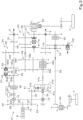
- FIG. 3 illustrates a power transmitting system 21 that transmits the power of the engine 8.
- the power transmitting system 21 includes a transmitting mechanism 22 that distributively transmits the power of the engine 8, a travel-related power transmitting system 23 that transmits the power of the engine 8 to the drive wheels (the front wheels 4 and/or the rear wheels 5), and a PTO power transmitting system 24 that transmits the power of the engine 8 to the PTO shaft 9.
- the transmitting mechanism 22 includes an input gear 25 and a pair of transmitting gears 26 and 27.
- the power of the engine 8 after the flywheel 15 and the main clutch 16 is transmitted to the input gear 25.
- the input gear 25 meshes with the pair of transmitting gears 26 and 27 and transmits the power to the pair of transmitting gears 26 and 27.
- the first transmitting gear 26 as one of the gears in the pair of transmitting gears 26 and 27 rotates integrally with a first transmitting shaft 29.
- the second transmitting gear 27 as the other one of the gears in the pair of transmitting gears 26 and 27 rotates integrally with a second transmitting shaft 30.
- the travel-related power transmitting system 23 includes a continuously variable transmission 17 to which the power from the engine 8 is transmitted, and the travel-related transmitting mechanism 20 that speed-changes the power output from the continuously variable transmission 17 and transmits the power to the drive wheels.
- the planetary gear mechanism 47 includes a sun gear 47a, a plurality of planetary gears 47b provided around the sun gear 47a, a carrier 47c that rotatably supports each planetary gear 47b, a ring gear 47d that meshes with the plurality of planetary gears 47b, and an output shaft 47e that outputs power.
- Rotational power output from a motor shaft 33 of the HST motor 19 is input to the sun gear 47a.
- Rotational power of the second transmitting shaft 30 is input to the carrier 47c.
- the planetary gear mechanism 47 combines a driving force from the continuously variable transmission 17 with a driving force from the engine 8 not affected by a speed-changing operation of the continuously variable transmission 17, and outputs the combined driving force from the output shaft 47e to an input shaft 48a of the forward-rearward-travel switching mechanism 48.
- the forward-rearward-travel switching mechanism 48 outputs the driving force transmitted to the input shaft 48a from either of a forward-travel output gear train 48b that transmits forward-travel power and a rearward-travel gear train 48c that transmits rearward-travel power.
- the forward-rearward-travel switching mechanism 48 includes a switch clutch 48d that switches the power transmitting mode between a forward-travel-power transmitting mode and a rearward-travel-power transmitting mode.
- the secondary transmission mechanism 49 switches power output from an output shaft 48e of the forward-rearward-travel switching mechanism 48 to any of a lower speed mode, an intermediate speed mode, and a high speed mode, and outputs the power.
- the power output from the secondary transmission mechanism 49 is transmitted to the rear wheels 5 via a rear-wheel differential mechanism 50.
- the power output from the secondary transmission mechanism 49 is transmitted to the front wheels 4 via a front-wheel-power extracting gear train 51, a clutch mechanism 52, a front-wheel-power transmitting shaft 53, a front-wheel differential mechanism 54, and the like.
- the PTO power transmitting system 24 includes a PTO clutch 56, a PTO transmission mechanism 57, a final transmitting shaft 58, and a relay gear train 59.
- the PTO power transmitting system 24 is accommodated inside the transmission case 14.
- the PTO clutch 56 is a device that intermittently transmits power from the first transmitting shaft 29 (engine 8).
- the PTO clutch 56 transmits the power to the PTO transmission mechanism 57 in a clutch-connected state.
- the PTO clutch 56 includes a wet multi-plate hydraulic clutch that transitions into a clutch-connected state by being supplied with oil (pressure oil) and that transitions into a clutch-disconnected state by discharging the oil.
- the PTO clutch 56 is supplied with or discharges the oil via an electromagnetic switching valve 60 as an electromagnetic switching valve. In other words, the PTO clutch 56 undergoes intermittent control of power by the electromagnetic switching valve 60.
- the electromagnetic switching valve 60 is connected to a controller 61, and is controlled by the controller 61.
- the PTO transmission mechanism 57 speed-changes the power transmitted via the PTO clutch 56.
- the PTO transmission mechanism 57 includes a first PTO transmission shaft 62, a second PTO transmission shaft 63, a first gear train 64 and a second gear train 65, and a switching mechanism 66.
- the power from the first transmitting shaft 29 (engine 8) is transmitted to the first PTO transmission shaft 62 via the PTO clutch 56.
- the second PTO transmission shaft 63 transmits the power to the PTO shaft 9.
- the first gear train 64 and the second gear train 65 transmit the power from the first PTO transmission shaft 62 to the second PTO transmission shaft 63.
- the first gear train 64 includes a driving gear 64a that rotates integrally with the first PTO transmission shaft 62, and a driven gear 64b that meshes with the driving gear 64a and that is fitted to the second PTO transmission shaft 63 in a relatively rotatable manner.
- the second gear train 65 includes a driving gear 65a that rotates integrally with the first PTO transmission shaft 62, and a driven gear 65b that meshes with the driving gear 65a and that is fitted to the second PTO transmission shaft 63 in a relatively rotatable manner.
- the first gear train 64 transmits power to the PTO shaft 9 when the rotation speed of the engine 8 is a first rotation speed.
- the second gear train 65 transmits power to the PTO shaft 9 when the rotation speed of the engine 8 is a second rotation speed different from the first rotation speed.
- the second rotation speed is a rotation speed greater than the first rotation speed. Therefore, the second gear train 65 reduces the speed of rotational power of the first PTO transmission shaft 62 relative to the first gear train 64, and transmits the rotational power to the second PTO transmission shaft 63.
- a gear ratio of the first gear train 64 and a gear ratio of the second gear train 65 are determined such that a rotation speed of the PTO shaft 9 when the rotation speed of the engine 8 is the first rotation speed is substantially equal to a rotation speed of the PTO shaft 9 when the rotation speed of the engine 8 is the second rotation speed.
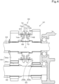
- the switching mechanism 66 is a synchromesh switching mechanism configured to switch the power transmission from the first PTO transmission shaft 62 to the second PTO transmission shaft 63 between a first mode where the power transmission is performed via the first gear train 64 and a second mode where the power transmission is performed via the second gear train 65.
- the switching mechanism 66 is disposed between a driven gear (referred to as a first driven gear) 64b of the first gear train 64 and a driven gear (referred to as a second driven gear) 65b of the second gear train 65.
- the first driven gear 64b is provided with a first spline portion 67 and a first cone portion 68 that is conical.
- the second driven gear 65b is provided with a second spline portion 69 and a second cone portion 70 that is conical.
- the switching mechanism 66 includes a coupling 71, a shifter 72, at least one synchronizer key 73, and a pair of synchronizer rings 74A and 74B.
- the coupling 71 is fitted to the second PTO transmission shaft 63 in an integrally rotatable manner.
- the shifter 72 is tubular and is fitted to the outer periphery of the coupling 71 by spline-fitting.
- the shifter 72 is rotatable integrally with the coupling 71 and is movable in the axial direction of the second PTO transmission shaft 63 relative to the coupling 71.
- the at least one synchronizer key 73 includes a plurality of synchronizer keys 73 respectively fitted in a plurality of key grooves provided in the outer periphery of the coupling 71.
- a protrusion 73a of each synchronizer key 73 is fitted in a groove of the shifter 72, and the synchronizer key 73 is pressed against the shifter 72 by a spring.
- One synchronizer ring (referred to as a first synchronizer ring) 74A of the pair of synchronizer rings 74A and 74B includes a spline portion 74a at the outer periphery thereof, and is disposed at the outer periphery of the first cone portion 68.
- the other synchronizer ring (referred to as a second synchronizer ring) 74B of the pair of synchronizer rings 74A and 74B includes a spline portion 74b at the outer periphery thereof, and is disposed at the outer periphery of the second cone portion 70.
- the shifter 72 When the shifter 72 receives a force applied in a direction that causes it to move to the first driven gear 64b, the shifter 72 starts to move toward the driven gear 64b. This causes the synchronizer key 73 pressed by the shifter 72 to press the first synchronizer ring 74A against the first cone portion 68. A frictional force generated between the first synchronizer ring 74A and the first cone portion 68 causes a start of transmission of the rotation of the coupling 71 and the synchronizer key 73 to the first synchronizer ring 74A and the first driven gear 64b.
- the shifter 72 When the rotation of the shifter 72 and the rotation of the first driven gear 64b match (synchronize), the shifter 72 sequentially meshes with the first synchronizer ring 74A and the first spline portion 67. Accordingly, the rotational power of the first PTO transmission shaft 62 is transmitted to the second PTO transmission shaft 63 sequentially via the first driving gear, the first driven gear 64b, the shifter 72, and the coupling 71.
- the final transmitting shaft 58 rotates integrally with the PTO shaft 9.
- the relay gear train 59 transmits power output from the PTO transmission mechanism 57 to the final transmitting shaft 58.
- the PTO power transmitting system 24 includes a power extracting gear 75.
- the power extracting gear 75 is attached to the final transmitting shaft 58 in an integrally rotatable manner. Rotational power of the power extracting gear 75 is transmitted to a power extracting portion 102 via a gear transmitting mechanism 76.
- the power extracting portion 102 is capable of transmitting power intermittently to a working machine, such as a mid-mount mower, attached to a lower portion of the tractor 1.
- the tractor 1 includes a shift fork 77 that performs a switching operation of the switching mechanism 66 to switch the power transmission from the first PTO transmission shaft 62 to the second PTO transmission shaft 63 to the first mode or the second mode.
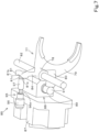
- the shift fork 77 includes a boss 78, a main body 79, a connector 80, and a detection portion 81.
- the boss 78 is supported by a support rod 82 in a slidable manner.
- the support rod 82 is disposed parallel to the second PTO transmission shaft 63 (see FIG. 6 ). Therefore, the shift fork 77 is movable in the axial direction of the second PTO transmission shaft 63. Opposite axial ends of the support rod 82 are supported by the transmission case 14.
- the main body 79 is bifurcated and is engaged with an engagement groove 72a in the shifter 72. With the main body 79 being engaged with the shifter 72, the shift fork 77 and the shifter 72 are integrally movable.
- the base portion of the main body 79 is provided with the boss 78.
- the connector 80 is provided at the base portion of the main body 79.
- the connector 80 has a shape that protrudes rightward from the base portion.
- the connector 80 is located below the boss 78.
- the connector 80 includes a connection hole 83 that is open rightward.
- the detection portion 81 is provided at an upper portion of an extending portion 84 extending upward from the boss 78.
- the detection portion 81 includes a first engagement portion 81a, a second engagement portion 81b, and a recess 81c at the right surface.
- the first engagement portion 81a is provided at the front of the detection portion 81.
- the second engagement portion 81b is provided at the rear of the detection portion 81.
- the recess 81c is provided between the first engagement portion 81a and the second engagement portion 81b.
- the tractor 1 includes an operation mechanism 85 for operating the shift fork 77 to perform the switching operation of the switching mechanism 66 by using the shift fork 77.
- the operation mechanism 85 is disposed rightward of the shift fork 77.
- the operation mechanism 85 includes a transmission valve 86, a main body 87, and a shift cylinder 88.
- the transmission valve 86 includes an electromagnetic valve.
- the transmission valve 86 is connected to the controller 61.
- the transmission valve 86 is operationally controlled in accordance with a control signal output from the controller 61.
- the main body 87 contains the transmission valve 86 therein.
- the main body 87 includes a fluid passage for guiding oil (pressure oil) supplied from a hydraulic pump equipped in the tractor 1 to the transmission valve 86 and the shift cylinder 88.
- the main body 87 is attached to an outer surface of a right sidewall 14a of the transmission case 14 (see FIG. 5 ).
- the shift cylinder 88 moves the shift fork 77 to perform the switching operation of the switching mechanism 66.
- the shift cylinder 88 includes a cylinder body 89, a piston 90, and a piston rod 91.
- the cylinder body 89 is provided at a left portion of the main body 87.
- the cylinder body 89 is integrally molded with the main body 87. Specifically, the main body 87 and the cylinder body 89 are a single-piece object.
- the cylinder body 89 is inserted into the transmission case 14 via an open hole 92 provided in the right sidewall 14a of the transmission case 14.
- the cylinder body 89 includes a cylinder chamber 89a and a rod insertion hole 89b that communicates with a front portion of the cylinder chamber 89a and that is open forward.
- the piston 90 is movable in the front-rear direction K1 (direction parallel to the axis of the first PTO transmission shaft 62) inside the cylinder chamber 89a.
- the piston rod 91 is connected to the front surface of the piston 90 and is inserted through the rod insertion hole 89b.
- a pin insertion hole 93 is provided at the distal end of the piston rod 91.
- a connection pin 94 is inserted through the pin insertion hole 93 and a connection hole 83 in the shift fork 77.
- the piston rod 91 and the shift fork 77 are connected by the connection pin 94.
- the transmission valve 86 to control the supply and discharge of the oil to and from the cylinder chamber 89a, the piston rod 91 protrudes and retracts relative to the cylinder body 89.
- the protrusion and retraction of the piston rod 91 cause the shift fork 77 to move.
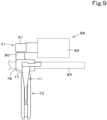
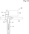
- the piston 90 is switchable between a first shift position X1 ( FIG. 9 ) and a second shift position X2 ( FIG. 10 ) in accordance with the transmission valve 86.
- the first shift position X1 is a position where the shift fork 77 is moved to a first operational position Y1 and where the shifter 72 is meshed with the first spline portion 67 of the first driven gear 64b.
- the first shift position X1 is a position where the power transmission from the first PTO transmission shaft 62 to the second PTO transmission shaft 63 has been switched to the first mode.
- the first operational position Y1 of the shift fork 77 is a position where the switching mechanism 66 has switched the power transmission from the first PTO transmission shaft 62 to the second PTO transmission shaft 63 to the first mode.
- the second shift position X2 is a position where the shift fork 77 is moved to a second operational position Y2 and where the shifter 72 is meshed with the second spline portion 69 of the second driven gear 65b.
- the second shift position X2 is a position where the power transmission from the first PTO transmission shaft 62 to the second PTO transmission shaft 63 has been switched to the second mode.
- the second operational position Y2 of the shift fork 77 is a position where the switching mechanism 66 has switched the power transmission from the first PTO transmission shaft 62 to the second PTO transmission shaft 63 to the second mode.
- the tractor 1 includes a detecting mechanism 95 that detects the position of the shift fork 77.
- the detecting mechanism 95 includes a detection sensor 96 and a pressing member 97.
- the detection sensor 96 is retained by a retainer 98 provided at the sidewall 14a of the transmission case 14.
- the pressing member 97 is interposed between the detection sensor 96 and the detection portion 81 of the shift fork 77.
- the pressing member 97 is supported by a support, not illustrated, provided at the transmission case 14 in a movable manner in the vehicle-body width direction.
- the pressing member 97 abuts on the first engagement portion 81a of the shift fork 77 so that the pressing member 97 presses and moves a contact 96a of the detection sensor 96, whereby the detection sensor 96 detects that the shift fork 77 is in a position (first operational position Y1) where the shifter 72 is meshed with the first spline portion 67.
- the pressing member 97 abuts on the second engagement portion 81b of the shift fork 77 so that the pressing member 97 presses and moves the contact 96a of the detection sensor 96, whereby the detection sensor 96 detects that the shift fork 77 is in a position (second operational position Y2) where the shifter 72 is meshed with the second spline portion 69.
- the shift fork 77 includes the detection portion 81 that is movable between the first operational position Y1 and the second operational position Y2 and that is for causing the detection sensor 96 to detect that the shift fork 77 is in the first operational position Y1 or the second operational position Y2.
- the detecting mechanism 95 may include the detection sensor 96 alone. In this case, the contact 96a of the detection sensor 96 is brought into abutment with the detection portion 81.
- the tractor 1 includes a transmission switch (switch) 99.
- the transmission switch 99 is disposed near the operator's seat 2.
- the transmission switch 99 is for outputting at least an operational signal for operating the operation mechanism 85.
- the transmission switch 99 outputs an operational signal for switching the rotation speed of the engine 8 and for operating the operation mechanism 85.
- the transmission switch 99 is connected to the controller 61.
- the controller 61 is capable of acquiring the operational signal output from the transmission switch 99.
- the controller 61 is also connected to an engine control unit (ECU) 100 that controls the rotation speed of the engine 8.
- ECU engine control unit
- the transmission switch 99 includes a rotary switch manually rotated by the operator.
- the transmission switch 99 is switchable among a first position 101a, a second position 101b, and a third position 101c.
- the controller 61 acquires the operational signal from the transmission switch 99 and outputs a control signal (first control signal) to the ECU 100 and the operation mechanism 85 (transmission valve 86).
- first control signal a control signal
- the ECU 100 switches the rotation speed of the engine 8 to the first rotation speed and fixes the rotation speed to the first rotation speed.
- the operation mechanism 85 actuates the shift cylinder 88 to move the shift fork 77 to the first operational position Y1, and switches the switching mechanism 66 such that the power transmission from the first PTO transmission shaft 62 to the second PTO transmission shaft 63 is in the first mode.
- the controller 61 acquires the operational signal from the transmission switch 99 and outputs a control signal (second control signal) to the ECU 100 and the operation mechanism 85 (transmission valve 86).
- the ECU 100 switches the rotation speed of the engine 8 to the second rotation speed and fixes the rotation speed to the second rotation speed.
- the operation mechanism 85 (transmission valve 86) actuates the shift cylinder 88 to move the shift fork 77 to the second operational position Y2, and switches the switching mechanism 66 such that the power transmission from the first PTO transmission shaft 62 to the second PTO transmission shaft 63 is in the second mode.
- the controller 61 acquires the operational signal from the transmission switch 99 and outputs a control signal (third control signal) to the ECU 100.
- the ECU 100 does not fix the rotation speed of the engine 8 to a specific rotation speed.
- the rotation speed of the engine 8 is controlled to a rotation speed set in accordance with an operation of an accelerator member manually operated by the operator.
- the controller 61 does not output a control signal to the operation mechanism 85 (transmission valve 86) when the transmission switch 99 is switched to the third position 101c.
- the switching mechanism 66 is not switched to a neutral position.
- the electromagnetic switching valve 60 may acquire a third control signal, and the PTO clutch 56 may be switched to the clutch-disconnected state by the electromagnetic switching valve 60.
- the PTO clutch 56 may be switched between the clutch-connected state and the clutch-disconnected state in accordance with an operation by the operator different from the operation of the transmission switch 99.
- the preferred embodiment of the present invention provides the working vehicle 1 according to the following items.
- a working vehicle comprising a PTO shaft to extract power of a prime mover to an outside, a first PTO transmission shaft to receive power from the prime mover, a second PTO transmission shaft to transmit power to the PTO shaft, a first gear train and a second gear train to transmit power from the first PTO transmission shaft to the second PTO transmission shaft, and a synchromesh switching mechanism to switch power transmission from the first PTO transmission shaft to the second PTO transmission shaft between a first mode where the power transmission is performed via the first gear train and a second mode where the power transmission is performed via the second gear train.
- the synchromesh switching mechanism 66 is configured to switch the power transmission from the first PTO transmission shaft 62 to the second PTO transmission shaft 63 between the first mode where the power transmission is performed via the first gear train 64 and the second mode where the power transmission is performed via the second gear train 65, whereby the transmission operation of the PTO power transmitting system can be performed by electronic control using a switch.
- (Item 2) The working vehicle according to Item 1, further comprising a shift fork to perform a switching operation of the switching mechanism to switch the power transmission between the first mode and the second mode, an operation mechanism to operate the shift fork to cause the shift fork to perform the switching operation of the switching mechanism, a switch operable to output an operational signal to operate the operation mechanism, and a controller configured or programmed to, when acquiring the operational signal from the switch, output a control signal to actuate the operation mechanism.
- the operation mechanism 85 is actuated in accordance with the control signal output from the controller 61 by operating the switch 99, and the switching operation of the switching mechanism 66 is performed by operating the shift fork 77 using the operation mechanism 85, whereby the transmission operation of the PTO power transmitting system can be performed by electronic control using a switch.
- the output horsepower to be output from the PTO shaft 9 can be increased while keeping the rotation speed of the PTO shaft 9 constant.
- the switching between the first mode and the second mode can be performed automatically in conjunction with the switching between the first rotation speed and the second rotation speed by operating the switch 99.
- the switching between the first mode and the second mode can be performed automatically in accordance with the shift cylinder 88 that moves the shift fork 77 and the transmission valve 86 that actuates the shift cylinder 88.
- a moving operation of the shift fork 77 can be performed in accordance with the shift cylinder 88.
- (Item 7) The working vehicle according to item 2 or any one of items 3, 4, 5, and 6 as dependent on item 2, further comprising: a detection sensor to detect a position of the shift fork, wherein the shift fork includes a detectable portion that is movable between a first operational position and a second operational position and is to be detected by the detection sensor to enable the detection sensor to detect whether the shift fork is in the first operational position or the second operational position, the first operational position is a position where the power transmission from the first PTO transmission shaft to the second PTO transmission shaft is switched to the first mode by the switching mechanism, and the second operational position is a position where the power transmission from the first PTO transmission shaft to the second PTO transmission shaft is switched to the second mode by the switching mechanism.
Landscapes
- Engineering & Computer Science (AREA)
- General Engineering & Computer Science (AREA)
- Mechanical Engineering (AREA)
- Chemical & Material Sciences (AREA)
- Combustion & Propulsion (AREA)
- Transportation (AREA)
- Arrangement And Driving Of Transmission Devices (AREA)
- Gear-Shifting Mechanisms (AREA)
Abstract
A working vehicle (1) includes a PTO shaft (9) to extract power of a prime mover (8) to the outside, a first PTO transmission shaft (62) to receive power from the prime mover (8), a second PTO transmission shaft (63) to transmit power to the PTO shaft (9), a first gear train (64) and a second gear train (65) to transmit power from the first PTO transmission shaft (62) to the second PTO transmission shaft (63), and a synchromesh switching mechanism (66) to switch power transmission from the first PTO transmission shaft (62) to the second PTO transmission shaft (63) between a first mode where the power transmission is performed via the first gear train (64) and a second mode where the power transmission is performed via the second gear train (65).
Description
- The present invention relates to working vehicles.
- A known working vehicle in the related art is disclosed in
Japanese Unexamined Patent Application Publication No. 2020-189532 - The working vehicle disclosed in
Japanese Unexamined Patent Application Publication No. 2020-189532 - The PTO transmission mechanism includes a first gear train and a second gear train that transmit power to a second PTO transmission shaft, which transmits the power to the PTO shaft, from a first PTO transmission shaft that receives the power of the prime mover. The PTO transmission mechanism is configured to switch the power transmission from the first PTO transmission shaft to the second PTO transmission shaft between a first mode where the power transmission is performed via the first gear train and a second mode where the power transmission is performed via the second gear train.
- There are demands in the related art to perform a transmission operation of the PTO-based power transmitting system by electronic control using a switch.
- In view of the aforementioned problem, an object of the present invention is to provide working vehicles each that may perform a transmission operation of a PTO power transmitting system by electronic control using a switch.
- A working vehicle includes a PTO shaft to extract power of a prime mover to an outside, a first PTO transmission shaft to receive power from the prime mover, a second PTO transmission shaft to transmit power to the PTO shaft, a first gear train and a second gear train to transmit power from the first PTO transmission shaft to the second PTO transmission shaft, and a synchromesh switching mechanism to switch power transmission from the first PTO transmission shaft to the second PTO transmission shaft between a first mode where the power transmission is performed via the first gear train and a second mode where the power transmission is performed via the second gear train.
- The working vehicle may include a shift fork to perform a switching operation of the switching mechanism to switch the power transmission between the first mode and the second mode, an operation mechanism to operate the shift fork to cause the shift fork to perform the switching operation of the switching mechanism, a switch operable to output an operational signal to operate the operation mechanism, and a controller configured or programmed to, when acquiring the operational signal from the switch, output a control signal to actuate the operation mechanism.
- The first gear train may be configured to transmit the power to the PTO shaft when a rotation speed of the prime mover is a first rotation speed. The second gear train may be configured to transmit the power to the PTO shaft when the rotation speed of the prime mover is a second rotation speed different from the first rotation speed. A gear ratio of the first gear train and a gear ratio of the second gear train may be determined such that a rotation speed of the PTO shaft when the rotation speed of the prime mover is the first rotation speed is substantially equal to a rotation speed of the PTO shaft when the rotation speed of the prime mover is the second rotation speed.
- The controller may be configured or programmed to, when acquiring the operational signal from the switch, switch the rotation speed of the prime mover to the first rotation speed or the second rotation speed and output the control signal to the operation mechanism to switch the power transmission to the first mode or the second mode depending on whether the rotation speed of the prime mover is the first rotation speed or the second rotation speed.
- The operation mechanism may include a shift cylinder to move the shift fork to perform the switching operation, and a transmission valve to be controlled in accordance with the control signal to actuate the shift cylinder.
- The shift cylinder may include a cylinder body and a piston rod to protrude and retract relative to the cylinder body. The shift fork may include a connector to be connected to the piston rod via a connection pin.
- The working vehicle may include a detection sensor to detect a position of the shift fork. The shift fork may include a detectable portion that is movable between a first operational position and a second operational position and is to be detected by the detection sensor to enable the detection sensor to detect whether the shift fork is in the first operational position or the second operational position. The first operational position may be a position where the power transmission from the first PTO transmission shaft to the second PTO transmission shaft is switched to the first mode by the switching mechanism. The second operational position may be a position where the power transmission from the first PTO transmission shaft to the second PTO transmission shaft is switched to the second mode by the switching mechanism.
- According to the working vehicle described above, the synchromesh switching mechanism is configured to switch the power transmission from the first PTO transmission shaft to the second PTO transmission shaft between the first mode where the power transmission is performed via the first gear train and the second mode where the power transmission is performed via the second gear train, so that the transmission operation of the PTO power transmitting system can be performed by electronic control using a switch.
- The above and other elements, features, steps, characteristics and advantages of the present invention will become more apparent from the following detailed description of the example embodiments with reference to the attached drawings.
- A more complete appreciation of example embodiments of the present invention and many of the attendant advantages thereof will be readily obtained as the same becomes better understood by reference to the following detailed description when considered in connection with the accompanying drawings described below.
-
FIG. 1 is a side view of a working vehicle. -
FIG. 2 is a side view of a power transmitting case. -
FIG. 3 is a power transmitting system diagram illustrating a power transmitting system of an engine. -
FIG. 4 is a cross-sectional view illustrating a PTO transmission mechanism. -
FIG. 5 is a front sectional view illustrating a shift fork, an operation mechanism, and the like. -
FIG. 6 is a plan view illustrating the shift fork, the operation mechanism, and the like. -
FIG. 7 is a perspective view illustrating the shift fork, the operation mechanism, and the like. -
FIG. 8 is a perspective view illustrating the shift fork and a detection sensor. -
FIG. 9 is a plan view illustrating the operation of a shift cylinder and the position of the shift fork. -
FIG. 10 is a plan view illustrating the operation of the shift cylinder and the position of the shift fork. - Example embodiments will now be described with reference to the accompanying drawings, wherein like reference numerals designate corresponding or identical elements throughout the various drawings. The drawings are to be viewed in an orientation in which the reference numerals are viewed correctly.
- Example embodiments of the present invention will be described below while referring to the drawings, as appropriate.
-
FIG. 1 illustrates a side view of aworking vehicle 1 according to this embodiment. In this embodiment, a tractor is illustrated as an example of theworking vehicle 1. Although the workingvehicle 1 is described as being a tractor below, the workingvehicle 1 is not limited to a tractor. - As illustrated in
FIG. 1 , thetractor 1 includes an operator's seat 2 where an operator sits. - In the following description, a direction extending forward (direction of an arrow Al in
FIG. 1 ) from the operator sitting in the operator's seat 2 will be described as a forward direction, and a direction extending rearward (direction of an arrow A2 inFIG. 1 ) from the operator will be described as a rearward direction. A direction extending leftward (toward the viewer ofFIG. 1 ) from the operator will be described as a leftward direction, and a direction extending rightward (away from the viewer ofFIG. 1 ) will be described as a rightward direction. - A direction indicated by an arrow K1 in
FIG. 1 will be described as a front-rear direction. A horizontal direction orthogonal to the front-rear direction K1 will be described as a vehicle-body width direction. In the vehicle-body width direction, a direction extending from the middle to the right or the left of thetractor 1 will be described as a vehicle-body-width outward direction. In the vehicle-body width direction, a direction extending from the right or the left of thetractor 1 to the middle of thetractor 1 will be described as a vehicle-body-width inward direction. - As illustrated in
FIG. 1 , thetractor 1 includes avehicle body 3,front wheels 4 disposed at the left and right of a front portion of thevehicle body 3,rear wheels 5 disposed at the left and right of a rear portion of thevehicle body 3, and anoperation portion 7 disposed higher than thevehicle body 3 and including asteering wheel 6, the operator's seat 2, and the like. Thefront wheels 4 are steered wheels that are steerable. In this embodiment, thefront wheels 4 and therear wheels 5 are drive wheels that are drivable. The drive wheels may be therear wheels 5 alone, or may be thefront wheels 4 alone. Thefront wheels 4 and therear wheels 5 constitute a traveling device that supports thevehicle body 3 in a travelable manner. - As illustrated in
FIG. 1 , thevehicle body 3 includes an engine (prime mover) 8 as a power source, a front frame coupled to theengine 8 and protruding forward from theengine 8, and a power transmittingcase 10 coupled to a rear portion of theengine 8 and extending rearward from theengine 8. APTO shaft 9 that extracts power of theengine 8 to the outside is disposed at a rear portion of the power transmitting case 10 (vehicle body 3). - In this embodiment, the
engine 8 is a diesel engine. Theengine 8 may be a gasoline engine. The power source may be a prime mover other than an engine. For example, the power source may be an electric motor. - As illustrated in
FIG. 2 , thepower transmitting case 10 includes aflywheel housing 11 coupled to the rear portion of theengine 8, aclutch housing 12 coupled to a rear portion of theflywheel housing 11, a continuously-variable-transmission case 13 coupled to a rear portion of theclutch housing 12, and atransmission case 14 coupled to a rear portion of the continuously-variable-transmission case 13. - The
flywheel housing 11 accommodates aflywheel 15 that rotates integrally with a crankshaft of theengine 8. Theclutch housing 12 accommodates a main clutch 16 that intermittently transmits the power of theengine 8 transmitted via theflywheel 15. The continuously-variable-transmission case 13 accommodates a hydraulic pump (called an HST pump) 18 and a hydraulic motor (called an HST motor) 19 that are components of a continuously variable transmission (hydro-static continuously variable transmission (HST)) 17. Thetransmission case 14 accommodates a travel-related transmitting mechanism (seeFIG. 3 ) 20 that speed-changes power output from the continuouslyvariable transmission 17 and transmits the power to the drive wheels. -
FIG. 3 illustrates apower transmitting system 21 that transmits the power of theengine 8. Thepower transmitting system 21 includes atransmitting mechanism 22 that distributively transmits the power of theengine 8, a travel-relatedpower transmitting system 23 that transmits the power of theengine 8 to the drive wheels (thefront wheels 4 and/or the rear wheels 5), and a PTOpower transmitting system 24 that transmits the power of theengine 8 to thePTO shaft 9. - As illustrated in
FIG. 3 , the transmittingmechanism 22 includes an input gear 25 and a pair of transmittinggears 26 and 27. The power of theengine 8 after theflywheel 15 and the main clutch 16 is transmitted to the input gear 25. The input gear 25 meshes with the pair of transmittinggears 26 and 27 and transmits the power to the pair of transmittinggears 26 and 27. Thefirst transmitting gear 26 as one of the gears in the pair of transmittinggears 26 and 27 rotates integrally with a first transmitting shaft 29. The second transmitting gear 27 as the other one of the gears in the pair of transmittinggears 26 and 27 rotates integrally with asecond transmitting shaft 30. - As illustrated in
FIG. 3 , the travel-relatedpower transmitting system 23 includes a continuouslyvariable transmission 17 to which the power from theengine 8 is transmitted, and the travel-relatedtransmitting mechanism 20 that speed-changes the power output from the continuouslyvariable transmission 17 and transmits the power to the drive wheels. - As illustrated in
FIG. 3 , the travel-relatedtransmitting mechanism 20 includes aplanetary gear mechanism 47, a forward-rearward-travel switching mechanism 48, and asecondary transmission mechanism 49. - The
planetary gear mechanism 47 includes asun gear 47a, a plurality ofplanetary gears 47b provided around thesun gear 47a, acarrier 47c that rotatably supports eachplanetary gear 47b, aring gear 47d that meshes with the plurality ofplanetary gears 47b, and anoutput shaft 47e that outputs power. - Rotational power output from a
motor shaft 33 of theHST motor 19 is input to thesun gear 47a. Rotational power of thesecond transmitting shaft 30 is input to thecarrier 47c. Theplanetary gear mechanism 47 combines a driving force from the continuouslyvariable transmission 17 with a driving force from theengine 8 not affected by a speed-changing operation of the continuouslyvariable transmission 17, and outputs the combined driving force from theoutput shaft 47e to aninput shaft 48a of the forward-rearward-travel switching mechanism 48. - The forward-rearward-
travel switching mechanism 48 outputs the driving force transmitted to theinput shaft 48a from either of a forward-traveloutput gear train 48b that transmits forward-travel power and a rearward-travel gear train 48c that transmits rearward-travel power. The forward-rearward-travel switching mechanism 48 includes a switch clutch 48d that switches the power transmitting mode between a forward-travel-power transmitting mode and a rearward-travel-power transmitting mode. - The
secondary transmission mechanism 49 switches power output from anoutput shaft 48e of the forward-rearward-travel switching mechanism 48 to any of a lower speed mode, an intermediate speed mode, and a high speed mode, and outputs the power. The power output from thesecondary transmission mechanism 49 is transmitted to therear wheels 5 via a rear-wheel differential mechanism 50. The power output from thesecondary transmission mechanism 49 is transmitted to thefront wheels 4 via a front-wheel-power extractinggear train 51, aclutch mechanism 52, a front-wheel-power transmitting shaft 53, a front-wheel differential mechanism 54, and the like. - As illustrated in
FIG. 3 , the PTOpower transmitting system 24 includes a PTO clutch 56, aPTO transmission mechanism 57, afinal transmitting shaft 58, and arelay gear train 59. The PTOpower transmitting system 24 is accommodated inside thetransmission case 14. - The PTO clutch 56 is a device that intermittently transmits power from the first transmitting shaft 29 (engine 8). The PTO clutch 56 transmits the power to the
PTO transmission mechanism 57 in a clutch-connected state. For example, the PTO clutch 56 includes a wet multi-plate hydraulic clutch that transitions into a clutch-connected state by being supplied with oil (pressure oil) and that transitions into a clutch-disconnected state by discharging the oil. The PTO clutch 56 is supplied with or discharges the oil via anelectromagnetic switching valve 60 as an electromagnetic switching valve. In other words, the PTO clutch 56 undergoes intermittent control of power by theelectromagnetic switching valve 60. - As illustrated in
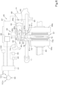
FIG. 6 , theelectromagnetic switching valve 60 is connected to acontroller 61, and is controlled by thecontroller 61. - The
PTO transmission mechanism 57 speed-changes the power transmitted via the PTO clutch 56. ThePTO transmission mechanism 57 includes a firstPTO transmission shaft 62, a secondPTO transmission shaft 63, afirst gear train 64 and asecond gear train 65, and aswitching mechanism 66. - The power from the first transmitting shaft 29 (engine 8) is transmitted to the first
PTO transmission shaft 62 via the PTO clutch 56. The secondPTO transmission shaft 63 transmits the power to thePTO shaft 9. Thefirst gear train 64 and thesecond gear train 65 transmit the power from the firstPTO transmission shaft 62 to the secondPTO transmission shaft 63. - The
first gear train 64 includes adriving gear 64a that rotates integrally with the firstPTO transmission shaft 62, and a drivengear 64b that meshes with thedriving gear 64a and that is fitted to the secondPTO transmission shaft 63 in a relatively rotatable manner. Thesecond gear train 65 includes adriving gear 65a that rotates integrally with the firstPTO transmission shaft 62, and a drivengear 65b that meshes with thedriving gear 65a and that is fitted to the secondPTO transmission shaft 63 in a relatively rotatable manner. - The
first gear train 64 transmits power to thePTO shaft 9 when the rotation speed of theengine 8 is a first rotation speed. Thesecond gear train 65 transmits power to thePTO shaft 9 when the rotation speed of theengine 8 is a second rotation speed different from the first rotation speed. In this embodiment, the second rotation speed is a rotation speed greater than the first rotation speed. Therefore, thesecond gear train 65 reduces the speed of rotational power of the firstPTO transmission shaft 62 relative to thefirst gear train 64, and transmits the rotational power to the secondPTO transmission shaft 63. - A gear ratio of the
first gear train 64 and a gear ratio of thesecond gear train 65 are determined such that a rotation speed of thePTO shaft 9 when the rotation speed of theengine 8 is the first rotation speed is substantially equal to a rotation speed of thePTO shaft 9 when the rotation speed of theengine 8 is the second rotation speed. By switching the rotation speed of theengine 8 from the first rotation speed to the second rotation speed, output horsepower to be output from thePTO shaft 9 can be increased while keeping the rotation speed of thePTO shaft 9 constant. - The
switching mechanism 66 is a synchromesh switching mechanism configured to switch the power transmission from the firstPTO transmission shaft 62 to the secondPTO transmission shaft 63 between a first mode where the power transmission is performed via thefirst gear train 64 and a second mode where the power transmission is performed via thesecond gear train 65. - As illustrated in
FIG. 4 , theswitching mechanism 66 is disposed between a driven gear (referred to as a first driven gear) 64b of thefirst gear train 64 and a driven gear (referred to as a second driven gear) 65b of thesecond gear train 65. The first drivengear 64b is provided with afirst spline portion 67 and afirst cone portion 68 that is conical. The second drivengear 65b is provided with asecond spline portion 69 and asecond cone portion 70 that is conical. - The
switching mechanism 66 includes acoupling 71, ashifter 72, at least onesynchronizer key 73, and a pair of synchronizer rings 74A and 74B. - The
coupling 71 is fitted to the secondPTO transmission shaft 63 in an integrally rotatable manner. Theshifter 72 is tubular and is fitted to the outer periphery of thecoupling 71 by spline-fitting. Thus, theshifter 72 is rotatable integrally with thecoupling 71 and is movable in the axial direction of the secondPTO transmission shaft 63 relative to thecoupling 71. - The at least one
synchronizer key 73 includes a plurality ofsynchronizer keys 73 respectively fitted in a plurality of key grooves provided in the outer periphery of thecoupling 71. Aprotrusion 73a of eachsynchronizer key 73 is fitted in a groove of theshifter 72, and thesynchronizer key 73 is pressed against theshifter 72 by a spring. - One synchronizer ring (referred to as a first synchronizer ring) 74A of the pair of synchronizer rings 74A and 74B includes a
spline portion 74a at the outer periphery thereof, and is disposed at the outer periphery of thefirst cone portion 68. The other synchronizer ring (referred to as a second synchronizer ring) 74B of the pair of synchronizer rings 74A and 74B includes aspline portion 74b at the outer periphery thereof, and is disposed at the outer periphery of thesecond cone portion 70. - Next, the operation of the
switching mechanism 66 will be described. - When the
shifter 72 receives a force applied in a direction that causes it to move to the first drivengear 64b, theshifter 72 starts to move toward the drivengear 64b. This causes thesynchronizer key 73 pressed by theshifter 72 to press thefirst synchronizer ring 74A against thefirst cone portion 68. A frictional force generated between thefirst synchronizer ring 74A and thefirst cone portion 68 causes a start of transmission of the rotation of thecoupling 71 and thesynchronizer key 73 to thefirst synchronizer ring 74A and the first drivengear 64b. - When the
shifter 72 is to move further, theshifter 72 and thesynchronizer key 73 become disengaged from each other to cause theshifter 72 alone to move, so that thefirst synchronizer ring 74A and theshifter 72 come into contact with each other at chamfered portions of the respective splines. Accordingly, a frictional force received by thefirst synchronizer ring 74A in the rotational direction is also added to the force pressing against thefirst synchronizer ring 74A, and the combined force presses thefirst synchronizer ring 74A against thefirst cone portion 68. Consequently, the rotational speed of the first drivengear 64b becomes equal to that of theshifter 72. In other words, the rotational speeds synchronize between the first drivengear 64b and theshifter 72. - When the rotation of the
shifter 72 and the rotation of the first drivengear 64b match (synchronize), theshifter 72 sequentially meshes with thefirst synchronizer ring 74A and thefirst spline portion 67. Accordingly, the rotational power of the firstPTO transmission shaft 62 is transmitted to the secondPTO transmission shaft 63 sequentially via the first driving gear, the first drivengear 64b, theshifter 72, and thecoupling 71. - Since the same operation as above applies to a case where the
shifter 72 is moved to the second drivengear 65b, the description will be omitted. - As illustrated in
FIG. 3 , thefinal transmitting shaft 58 rotates integrally with thePTO shaft 9. Therelay gear train 59 transmits power output from thePTO transmission mechanism 57 to thefinal transmitting shaft 58. - As illustrated in
FIG. 3 , the PTOpower transmitting system 24 includes apower extracting gear 75. Thepower extracting gear 75 is attached to thefinal transmitting shaft 58 in an integrally rotatable manner. Rotational power of thepower extracting gear 75 is transmitted to apower extracting portion 102 via agear transmitting mechanism 76. For example, thepower extracting portion 102 is capable of transmitting power intermittently to a working machine, such as a mid-mount mower, attached to a lower portion of thetractor 1. - As illustrated in
FIG. 5 , thetractor 1 includes ashift fork 77 that performs a switching operation of theswitching mechanism 66 to switch the power transmission from the firstPTO transmission shaft 62 to the secondPTO transmission shaft 63 to the first mode or the second mode. - As illustrated in
FIGS. 5 ,6 ,7 , and8 , theshift fork 77 includes aboss 78, amain body 79, aconnector 80, and adetection portion 81. Theboss 78 is supported by asupport rod 82 in a slidable manner. Thesupport rod 82 is disposed parallel to the second PTO transmission shaft 63 (seeFIG. 6 ). Therefore, theshift fork 77 is movable in the axial direction of the secondPTO transmission shaft 63. Opposite axial ends of thesupport rod 82 are supported by thetransmission case 14. - The
main body 79 is bifurcated and is engaged with anengagement groove 72a in theshifter 72. With themain body 79 being engaged with theshifter 72, theshift fork 77 and theshifter 72 are integrally movable. The base portion of themain body 79 is provided with theboss 78. Theconnector 80 is provided at the base portion of themain body 79. Theconnector 80 has a shape that protrudes rightward from the base portion. Theconnector 80 is located below theboss 78. Theconnector 80 includes aconnection hole 83 that is open rightward. - The
detection portion 81 is provided at an upper portion of an extendingportion 84 extending upward from theboss 78. Thedetection portion 81 includes afirst engagement portion 81a, asecond engagement portion 81b, and arecess 81c at the right surface. Thefirst engagement portion 81a is provided at the front of thedetection portion 81. Thesecond engagement portion 81b is provided at the rear of thedetection portion 81. Therecess 81c is provided between thefirst engagement portion 81a and thesecond engagement portion 81b. - As illustrated in
FIGS. 5 ,6 , and7 , thetractor 1 includes anoperation mechanism 85 for operating theshift fork 77 to perform the switching operation of theswitching mechanism 66 by using theshift fork 77. As illustrated inFIGS. 5 and6 , theoperation mechanism 85 is disposed rightward of theshift fork 77. - As illustrated in
FIG. 6 , theoperation mechanism 85 includes atransmission valve 86, amain body 87, and ashift cylinder 88. Thetransmission valve 86 includes an electromagnetic valve. Thetransmission valve 86 is connected to thecontroller 61. Thetransmission valve 86 is operationally controlled in accordance with a control signal output from thecontroller 61. - The
main body 87 contains thetransmission valve 86 therein. Themain body 87 includes a fluid passage for guiding oil (pressure oil) supplied from a hydraulic pump equipped in thetractor 1 to thetransmission valve 86 and theshift cylinder 88. Themain body 87 is attached to an outer surface of aright sidewall 14a of the transmission case 14 (seeFIG. 5 ). - The
shift cylinder 88 moves theshift fork 77 to perform the switching operation of theswitching mechanism 66. As illustrated inFIG. 6 , theshift cylinder 88 includes acylinder body 89, a piston 90, and apiston rod 91. Thecylinder body 89 is provided at a left portion of themain body 87. Thecylinder body 89 is integrally molded with themain body 87. Specifically, themain body 87 and thecylinder body 89 are a single-piece object. Thecylinder body 89 is inserted into thetransmission case 14 via anopen hole 92 provided in theright sidewall 14a of thetransmission case 14. - The
cylinder body 89 includes acylinder chamber 89a and arod insertion hole 89b that communicates with a front portion of thecylinder chamber 89a and that is open forward. The piston 90 is movable in the front-rear direction K1 (direction parallel to the axis of the first PTO transmission shaft 62) inside thecylinder chamber 89a. Thepiston rod 91 is connected to the front surface of the piston 90 and is inserted through therod insertion hole 89b. Apin insertion hole 93 is provided at the distal end of thepiston rod 91. Aconnection pin 94 is inserted through thepin insertion hole 93 and aconnection hole 83 in theshift fork 77. Thepiston rod 91 and theshift fork 77 are connected by theconnection pin 94. By using thetransmission valve 86 to control the supply and discharge of the oil to and from thecylinder chamber 89a, thepiston rod 91 protrudes and retracts relative to thecylinder body 89. The protrusion and retraction of thepiston rod 91 cause theshift fork 77 to move. - As illustrated in
FIGS. 9 and10 , the piston 90 is switchable between a first shift position X1 (FIG. 9 ) and a second shift position X2 (FIG. 10 ) in accordance with thetransmission valve 86. - As illustrated in
FIG. 9 , the first shift position X1 is a position where theshift fork 77 is moved to a first operational position Y1 and where theshifter 72 is meshed with thefirst spline portion 67 of the first drivengear 64b. Specifically, the first shift position X1 is a position where the power transmission from the firstPTO transmission shaft 62 to the secondPTO transmission shaft 63 has been switched to the first mode. In other words, the first operational position Y1 of theshift fork 77 is a position where theswitching mechanism 66 has switched the power transmission from the firstPTO transmission shaft 62 to the secondPTO transmission shaft 63 to the first mode. - As illustrated in
FIG. 10 , the second shift position X2 is a position where theshift fork 77 is moved to a second operational position Y2 and where theshifter 72 is meshed with thesecond spline portion 69 of the second drivengear 65b. Specifically, the second shift position X2 is a position where the power transmission from the firstPTO transmission shaft 62 to the secondPTO transmission shaft 63 has been switched to the second mode. In other words, the second operational position Y2 of theshift fork 77 is a position where theswitching mechanism 66 has switched the power transmission from the firstPTO transmission shaft 62 to the secondPTO transmission shaft 63 to the second mode. - As illustrated in
FIGS. 5 ,6 ,7 , and8 , thetractor 1 includes a detectingmechanism 95 that detects the position of theshift fork 77. The detectingmechanism 95 includes adetection sensor 96 and a pressingmember 97. As illustrated inFIG. 5 , thedetection sensor 96 is retained by aretainer 98 provided at thesidewall 14a of thetransmission case 14. The pressingmember 97 is interposed between thedetection sensor 96 and thedetection portion 81 of theshift fork 77. The pressingmember 97 is supported by a support, not illustrated, provided at thetransmission case 14 in a movable manner in the vehicle-body width direction. - The pressing
member 97 abuts on thefirst engagement portion 81a of theshift fork 77 so that the pressingmember 97 presses and moves acontact 96a of thedetection sensor 96, whereby thedetection sensor 96 detects that theshift fork 77 is in a position (first operational position Y1) where theshifter 72 is meshed with thefirst spline portion 67. Moreover, the pressingmember 97 abuts on thesecond engagement portion 81b of theshift fork 77 so that the pressingmember 97 presses and moves thecontact 96a of thedetection sensor 96, whereby thedetection sensor 96 detects that theshift fork 77 is in a position (second operational position Y2) where theshifter 72 is meshed with thesecond spline portion 69. - Accordingly, the
shift fork 77 includes thedetection portion 81 that is movable between the first operational position Y1 and the second operational position Y2 and that is for causing thedetection sensor 96 to detect that theshift fork 77 is in the first operational position Y1 or the second operational position Y2. - The detecting
mechanism 95 may include thedetection sensor 96 alone. In this case, thecontact 96a of thedetection sensor 96 is brought into abutment with thedetection portion 81. - As illustrated in
FIG. 6 , thetractor 1 includes a transmission switch (switch) 99. The transmission switch 99 is disposed near the operator's seat 2. The transmission switch 99 is for outputting at least an operational signal for operating theoperation mechanism 85. In this embodiment, the transmission switch 99 outputs an operational signal for switching the rotation speed of theengine 8 and for operating theoperation mechanism 85. The transmission switch 99 is connected to thecontroller 61. Thecontroller 61 is capable of acquiring the operational signal output from the transmission switch 99. Thecontroller 61 is also connected to an engine control unit (ECU) 100 that controls the rotation speed of theengine 8. - The transmission switch 99 includes a rotary switch manually rotated by the operator. The transmission switch 99 is switchable among a
first position 101a, asecond position 101b, and athird position 101c. - When the transmission switch 99 is switched (operated) to the
first position 101a, thecontroller 61 acquires the operational signal from the transmission switch 99 and outputs a control signal (first control signal) to theECU 100 and the operation mechanism 85 (transmission valve 86). Upon acquiring the first control signal, theECU 100 switches the rotation speed of theengine 8 to the first rotation speed and fixes the rotation speed to the first rotation speed. Upon acquiring the first control signal, the operation mechanism 85 (transmission valve 86) actuates theshift cylinder 88 to move theshift fork 77 to the first operational position Y1, and switches theswitching mechanism 66 such that the power transmission from the firstPTO transmission shaft 62 to the secondPTO transmission shaft 63 is in the first mode. - When the transmission switch 99 is switched (operated) to the
second position 101b, thecontroller 61 acquires the operational signal from the transmission switch 99 and outputs a control signal (second control signal) to theECU 100 and the operation mechanism 85 (transmission valve 86). Upon acquiring the second control signal, theECU 100 switches the rotation speed of theengine 8 to the second rotation speed and fixes the rotation speed to the second rotation speed. Upon acquiring the second control signal, the operation mechanism 85 (transmission valve 86) actuates theshift cylinder 88 to move theshift fork 77 to the second operational position Y2, and switches theswitching mechanism 66 such that the power transmission from the firstPTO transmission shaft 62 to the secondPTO transmission shaft 63 is in the second mode. - When the transmission switch 99 is switched to the
third position 101c, thecontroller 61 acquires the operational signal from the transmission switch 99 and outputs a control signal (third control signal) to theECU 100. Upon acquiring the third control signal, theECU 100 does not fix the rotation speed of theengine 8 to a specific rotation speed. In this case, for example, the rotation speed of theengine 8 is controlled to a rotation speed set in accordance with an operation of an accelerator member manually operated by the operator. Thecontroller 61 does not output a control signal to the operation mechanism 85 (transmission valve 86) when the transmission switch 99 is switched to thethird position 101c. Specifically, theswitching mechanism 66 is not switched to a neutral position. - For example, when the transmission switch 99 is switched to the
third position 101c, theelectromagnetic switching valve 60 may acquire a third control signal, and the PTO clutch 56 may be switched to the clutch-disconnected state by theelectromagnetic switching valve 60. The PTO clutch 56 may be switched between the clutch-connected state and the clutch-disconnected state in accordance with an operation by the operator different from the operation of the transmission switch 99. - The preferred embodiment of the present invention provides the working
vehicle 1 according to the following items. - (Item 1) A working vehicle comprising a PTO shaft to extract power of a prime mover to an outside, a first PTO transmission shaft to receive power from the prime mover, a second PTO transmission shaft to transmit power to the PTO shaft, a first gear train and a second gear train to transmit power from the first PTO transmission shaft to the second PTO transmission shaft, and a synchromesh switching mechanism to switch power transmission from the first PTO transmission shaft to the second PTO transmission shaft between a first mode where the power transmission is performed via the first gear train and a second mode where the power transmission is performed via the second gear train.
- In the working
vehicle 1 according toitem 1, thesynchromesh switching mechanism 66 is configured to switch the power transmission from the firstPTO transmission shaft 62 to the secondPTO transmission shaft 63 between the first mode where the power transmission is performed via thefirst gear train 64 and the second mode where the power transmission is performed via thesecond gear train 65, whereby the transmission operation of the PTO power transmitting system can be performed by electronic control using a switch. - (Item 2) The working vehicle according to
Item 1, further comprising a shift fork to perform a switching operation of the switching mechanism to switch the power transmission between the first mode and the second mode, an operation mechanism to operate the shift fork to cause the shift fork to perform the switching operation of the switching mechanism, a switch operable to output an operational signal to operate the operation mechanism, and a controller configured or programmed to, when acquiring the operational signal from the switch, output a control signal to actuate the operation mechanism. - In the working
vehicle 1 according to item 2, theoperation mechanism 85 is actuated in accordance with the control signal output from thecontroller 61 by operating the switch 99, and the switching operation of theswitching mechanism 66 is performed by operating theshift fork 77 using theoperation mechanism 85, whereby the transmission operation of the PTO power transmitting system can be performed by electronic control using a switch. - (Item 3) The working vehicle according to
item 1 or 2, wherein the first gear train is configured to transmit the power to the PTO shaft when a rotation speed of the prime mover is a first rotation speed, the second gear train is configured to transmit the power to the PTO shaft when the rotation speed of the prime mover is a second rotation speed different from the first rotation speed, and a gear ratio of the first gear train and a gear ratio of the second gear train are determined such that a rotation speed of the PTO shaft when the rotation speed of the prime mover is the first rotation speed is substantially equal to a rotation speed of the PTO shaft when the rotation speed of the prime mover is the second rotation speed. - In the working
vehicle 1 according toitem 3, when the rotation speed of theengine 8 is switched from a lower one of the first and second rotation speeds to a higher one of the first and second rotation speeds, the output horsepower to be output from thePTO shaft 9 can be increased while keeping the rotation speed of thePTO shaft 9 constant. - (Item 4) The working vehicle according to
item 3 as dependent on item 2, wherein the controller is configured or programmed to, when acquiring the operational signal from the switch, switch the rotation speed of the prime mover to the first rotation speed or the second rotation speed and output the control signal to the operation mechanism to switch the power transmission to the first mode or the second mode depending on whether the rotation speed of the prime mover is the first rotation speed or the second rotation speed. - In the working
vehicle 1 according toitem 4, the switching between the first mode and the second mode can be performed automatically in conjunction with the switching between the first rotation speed and the second rotation speed by operating the switch 99. - (Item 5) The working vehicle according to item 2 or
item - In the working
vehicle 1 according toitem 5, the switching between the first mode and the second mode can be performed automatically in accordance with theshift cylinder 88 that moves theshift fork 77 and thetransmission valve 86 that actuates theshift cylinder 88. - (Item 6) The working vehicle according to
item 5, wherein the shift cylinder includes a cylinder body and a piston rod to protrude and retract relative to the cylinder body, and the shift fork includes a connector to be connected to the piston rod via a connection pin. - In the working
vehicle 1 according toitem 6, a moving operation of theshift fork 77 can be performed in accordance with theshift cylinder 88. - (Item 7) The working vehicle according to item 2 or any one of
items - In the working
vehicle 1 according toitem 7, it is possible to detect whether the power transmission from the firstPTO transmission shaft 62 to the secondPTO transmission shaft 63 is in the first mode or the second mode. - While example embodiments of the present invention have been described above, it is to be understood that variations and modifications will be apparent to those skilled in the art without departing from the scope and spirit of the present invention. The scope of the present invention, therefore, is to be determined solely by the following claims.
Claims (7)
- A working vehicle (1) comprising:a PTO shaft (9) to extract power of a prime mover (8) to an outside;a first PTO transmission shaft (62) to receive power from the prime mover (8);a second PTO transmission shaft (63) to transmit power to the PTO shaft (9);a first gear train (64) and a second gear train (65) to transmit power from the first PTO transmission shaft (62) to the second PTO transmission shaft (63); anda synchromesh switching mechanism (66) to switch power transmission from the first PTO transmission shaft (62) to the second PTO transmission shaft (63) between a first mode where the power transmission is performed via the first gear train (64) and a second mode where the power transmission is performed via the second gear train (65).
- The working vehicle (1) according to claim 1, further comprising:a shift fork (77) to perform a switching operation of the switching mechanism (66) to switch the power transmission between the first mode and the second mode;an operation mechanism (85) to operate the shift fork (77) to cause the shift fork (77) to perform the switching operation of the switching mechanism (66);a switch (99) operable to output an operational signal to operate the operation mechanism (85); anda controller (61) configured or programmed to, when acquiring the operational signal from the switch (99), output a control signal to actuate the operation mechanism (85).
- The working vehicle (1) according to claim 1 or 2, whereinthe first gear train (64) is configured to transmit the power to the PTO shaft (9) when a rotation speed of the prime mover (8) is a first rotation speed,the second gear train (65) is configured to transmit the power to the PTO shaft (9) when the rotation speed of the prime mover (8) is a second rotation speed different from the first rotation speed, anda gear ratio of the first gear train (64) and a gear ratio of the second gear train (65) are determined such that a rotation speed of the PTO shaft (9) when the rotation speed of the prime mover (8) is the first rotation speed is substantially equal to a rotation speed of the PTO shaft (9) when the rotation speed of the prime mover (8) is the second rotation speed.
- The working vehicle (1) according to claim 3 as dependent on claim 2, wherein the controller (61) is configured or programmed to, when acquiring the operational signal from the switch (99), switch the rotation speed of the prime mover (8) to the first rotation speed or the second rotation speed and output the control signal to the operation mechanism (85) to switch the power transmission to the first mode or the second mode depending on whether the rotation speed of the prime mover (8) is the first rotation speed or the second rotation speed.
- The working vehicle (1) according to claim 2 or claim 3 or 4 as dependent on claim 2, wherein
the operation mechanism (85) includes:a shift cylinder (88) to move the shift fork (77) to perform the switching operation; anda transmission valve (86) to be controlled in accordance with the control signal to actuate the shift cylinder (88). - The working vehicle (1) according to claim 5, whereinthe shift cylinder (88) includes a cylinder body (89) and a piston rod (91) to protrude and retract relative to the cylinder body (89), andthe shift fork (77) includes a connector (80) to be connected to the piston rod (91) via a connection pin (94).
- The working vehicle (1) according to claim 2 or any one of claims 3, 4, 5, and 6 as dependent on claim 2, further comprising:a detection sensor (96) to detect a position of the shift fork (77), whereinthe shift fork (77) includes
a detectable portion (81) that is movable between a first operational position (Y1) and a second operational position (Y2) and is to be detected by the detection sensor (96) to enable the detection sensor (96) to detect whether the shift fork (77) is in the first operational position (Y1) or the second operational position (Y2),the first operational position (Y1) is a position where the power transmission from the first PTO transmission shaft (62) to the second PTO transmission shaft (63) is switched to the first mode by the switching mechanism (66), andthe second operational position (Y2) is a position where the power transmission from the first PTO transmission shaft (62) to the second PTO transmission shaft (63) is switched to the second mode by the switching mechanism (66).
Applications Claiming Priority (1)
| Application Number | Priority Date | Filing Date | Title |
|---|---|---|---|
| JP2023216819A JP2025099862A (en) | 2023-12-22 | 2023-12-22 | Working vehicle |
Publications (1)
| Publication Number | Publication Date |
|---|---|
| EP4574503A1 true EP4574503A1 (en) | 2025-06-25 |
Family
ID=93924328
Family Applications (1)
| Application Number | Title | Priority Date | Filing Date |
|---|---|---|---|
| EP24220156.4A Pending EP4574503A1 (en) | 2023-12-22 | 2024-12-16 | Working vehicle |
Country Status (3)
| Country | Link |
|---|---|
| US (1) | US12611928B2 (en) |
| EP (1) | EP4574503A1 (en) |
| JP (1) | JP2025099862A (en) |
Citations (6)
| Publication number | Priority date | Publication date | Assignee | Title |
|---|---|---|---|---|
| US20120310491A1 (en) * | 2009-11-19 | 2012-12-06 | Antoon Vermeulen | Tractor Comprising a Control System |
| US20130066496A1 (en) * | 2011-09-08 | 2013-03-14 | Norihiro Ishii | Hybrid Working Vehicle |
| DE102011084623A1 (en) * | 2011-10-17 | 2013-04-18 | Zf Friedrichshafen Ag | Power takeoff gear box e.g. four-level power takeoff gear box, for tractor, has spur gear stages for switching transmission stages, where each gear stage comprises gear wheels arranged on power-takeoff axles and shaft axle |
| EP2857246A2 (en) * | 2013-09-19 | 2015-04-08 | CLAAS Tractor S.A.S. | Agricultural work machine |
| JP2020189532A (en) | 2019-05-21 | 2020-11-26 | 株式会社 神崎高級工機製作所 | Transmission for work vehicle and hst unit |
| US20230018536A1 (en) * | 2019-12-19 | 2023-01-19 | Agco International Gmbh | Method of Operating an Agricultural Vehicle and a Transmission Arrangement for an Agricultural Vehicle |
Family Cites Families (2)
| Publication number | Priority date | Publication date | Assignee | Title |
|---|---|---|---|---|
| JP3921075B2 (en) * | 2001-11-07 | 2007-05-30 | 株式会社 神崎高級工機製作所 | Power take-out device for work vehicle |
| KR102714341B1 (en) * | 2021-11-23 | 2024-10-10 | 주식회사 진명파워텍 | Method of shifting transmission for work vehicle and transmission for work vehicle |
-
2023
- 2023-12-22 JP JP2023216819A patent/JP2025099862A/en active Pending
-
2024
- 2024-12-16 EP EP24220156.4A patent/EP4574503A1/en active Pending
- 2024-12-16 US US18/981,883 patent/US12611928B2/en active Active
Patent Citations (6)
| Publication number | Priority date | Publication date | Assignee | Title |
|---|---|---|---|---|
| US20120310491A1 (en) * | 2009-11-19 | 2012-12-06 | Antoon Vermeulen | Tractor Comprising a Control System |
| US20130066496A1 (en) * | 2011-09-08 | 2013-03-14 | Norihiro Ishii | Hybrid Working Vehicle |
| DE102011084623A1 (en) * | 2011-10-17 | 2013-04-18 | Zf Friedrichshafen Ag | Power takeoff gear box e.g. four-level power takeoff gear box, for tractor, has spur gear stages for switching transmission stages, where each gear stage comprises gear wheels arranged on power-takeoff axles and shaft axle |
| EP2857246A2 (en) * | 2013-09-19 | 2015-04-08 | CLAAS Tractor S.A.S. | Agricultural work machine |
| JP2020189532A (en) | 2019-05-21 | 2020-11-26 | 株式会社 神崎高級工機製作所 | Transmission for work vehicle and hst unit |
| US20230018536A1 (en) * | 2019-12-19 | 2023-01-19 | Agco International Gmbh | Method of Operating an Agricultural Vehicle and a Transmission Arrangement for an Agricultural Vehicle |
Also Published As
| Publication number | Publication date |
|---|---|
| US12611928B2 (en) | 2026-04-28 |
| US20250206131A1 (en) | 2025-06-26 |
| JP2025099862A (en) | 2025-07-03 |
Similar Documents
| Publication | Publication Date | Title |
|---|---|---|
| US9511666B2 (en) | Disconnectable driveline for all-wheel drive vehicle | |
| US6056666A (en) | Synchronized range shift mechanism for transfer case | |
| KR960015254B1 (en) | Shifting system for shifting engine power in a work vehicle and transmitting it to the drive wheels | |
| US5997428A (en) | Vehicle drive system including drive mode-shifting mechanism for shifting between two-wheel drive and four-wheel drive | |
| US5377800A (en) | Hydraulically-actuated shift system for a transfer case | |
| WO2013188647A1 (en) | Disconnectable driveline with a multi-speed rdm and ptu | |
| US5511436A (en) | Vehicle transmission assembly | |
| EP0924117B1 (en) | Four-wheel driven vehicle | |
| KR20170027992A (en) | Transmission assembly of Tractor | |
| JP4885349B2 (en) | transmission | |
| EP4574503A1 (en) | Working vehicle | |
| US4955848A (en) | Transfer device of four-wheel-drive vehicle | |
| JP5291064B2 (en) | transmission | |
| EP4438924A1 (en) | Method for speed-shifting work vehicle transmission, and work vehicle transmission | |
| US20070123386A1 (en) | Traveling System Auxiliary Speed Change Device | |
| JP4672852B2 (en) | transmission | |
| JP5016161B2 (en) | transmission | |
| JP2001322445A (en) | Two-wheel and four-wheel drive switching mechanism | |
| KR102583452B1 (en) | Hydraulic control valve device and transmission for work vehicle | |
| JP4666743B2 (en) | transmission | |
| JP2026066054A (en) | Work vehicles | |
| JP4034890B2 (en) | Agricultural tractor | |
| JP4528006B2 (en) | Four-wheel drive tractor travel device | |
| JP2000168383A (en) | Transmission for work vehicle | |
| JPH0231026A (en) | Gear shift operation structure of work vehicle |
Legal Events
| Date | Code | Title | Description |
|---|---|---|---|
| PUAI | Public reference made under article 153(3) epc to a published international application that has entered the european phase |
Free format text: ORIGINAL CODE: 0009012 |
|
| STAA | Information on the status of an ep patent application or granted ep patent |
Free format text: STATUS: REQUEST FOR EXAMINATION WAS MADE |
|
| 17P | Request for examination filed |
Effective date: 20241219 |
|
| AK | Designated contracting states |
Kind code of ref document: A1 Designated state(s): AL AT BE BG CH CY CZ DE DK EE ES FI FR GB GR HR HU IE IS IT LI LT LU LV MC ME MK MT NL NO PL PT RO RS SE SI SK SM TR |